Chemical Vapor Deposition of TaC/SiC on Graphite Tube and Its Ablation and Microstructure Studies

1
Directorate of Ceramics and CMCs, Defence Materials & Stores Research and Development Establishment, Defence Research and Development Organization, Kanpur 208013, India
2
Advanced Systems Laboratory, Defence Research and Development Organization, Hyderabad 500058, India
*
Author to whom correspondence should be addressed.
Coatings 2017, 7(7), 101; https://doi.org/10.3390/coatings7070101
Submission received: 15 June 2017
/
Revised: 8 July 2017
/
Accepted: 10 July 2017
/
Published: 13 July 2017
(This article belongs to the Special Issue Ultrahigh Temperature Ceramic Coatings and Composites)
Abstract
:Tantalum carbide (TaC) and silicon carbide (SiC) layers were deposited on a graphite tube using a chemical vapor deposition process. Tantalum chloride (TaCl5) was synthesized in situ by reacting tantalum chips with chlorine at 550 °C. TaC was deposited by reacting TaCl5 with CH4 in the presence of H2 at 1050–1150 °C and 50–100 mbar. SiC was deposited at 1000 °C using methyl-tri-chloro-silane as a precursor at 50 mbar. At 1150 °C; the coating thickness was found to be about 600 μm, while at 1050 °C it was about 400 μm for the cumulative deposition time of 10 h. X-ray diffraction (XRD) and X-ray Photo-Electron Spectroscopy (XPS) studies confirmed the deposition of TaC and SiC and their phases. Ablation studies of the coated specimens were carried out under oxyacetylene flame up to 120 s. The coating was found to be intact without surface cracks and with negligible erosion. The oxide phase of TaC (TaO2 and Ta2O5) and the oxide phase of SiC (SiO2) were also found on the surface, which may have protected the substrate underneath from further oxidation.
1. Introduction
C/C composites (carbon fibers embedded into a carbon matrix) are used for high temperature structural and aerospace applications due to their superior thermomechanical properties and high specific strength. However, C/C composites exhibit substantial oxidative damage under an oxidizing atmosphere >500 °C [1]. C/C composites suffer severe oxidative and erosive damage under high temperature flow conditions [2]. The oxidation and erosion resistance of C/C composites can be enhanced by employing Ultra High Temperature Ceramics (UHTCs) coatings [3]. Compared to boride UHTCs, carbide UHTCs (TaC, HfC, and ZrC etc.) are preferred due to their simpler synthesis processes [4,5,6].
Chemical vapor deposition (CVD) of UHTC by cracking metal-organic-precursors on the surface of the substrate is the most commonly used technique [7]. Reactive melt infiltration (RMI) of refractory metals into the porous carbonaceous composites is also used to convert the surface to UHTC [8]. The polymer impregnation and pyrolysis (PIP) process using polymer precursors of UHTCs is also employed for UHTC coatings. However, the CVD process is usually preferred over RMI and PIP processes as it provides a dense coating of UHTC with controlled composition and microstructure [4,7]. Moreover, the process temperature of CVD is much lower than that required for the RMI and PIP processes.
Due to its high melting point (4153–4273 K), high hardness, and excellent resistance to chemical and physical erosion, TaC has been proposed as an oxidation and erosion resistant coating for graphite [6,9,10]. In fact, TaC coating has been used as an oxidation and erosion resistant coating on the C/C nozzle throat of a solid rocket motor (SRM) [11,12]. Under an oxidizing atmosphere and high temperature, TaC reacts with oxygen and develops a molten tantalum-oxide protective film on the surface to further retard oxygen diffusion and oxidation of the substrate underneath.
However, the coefficient of thermal expansion (CTE) of TaC is much higher compared with that of C/C composites (roughly by more than four times) [9,12,13]. The CTE of SiC is lower compared to TaC, which also has good chemical stability and compatibility with graphite, and develops a protective layer of SiO2 under oxidation above 1600 °C [2,5,6]. Therefore, multilayered TaC/SiC coating has been used as an ablation resistance coating for C/C composites [9]. TaCl5 powder has been used as a tantalum source, which is evaporated at high temperature reacts with C2H6 in the presence of H2 to deposit TaC by the CVD technique [12,13]. TaCl5 powder is a special chemical and its uses for larger size products would affect the economics of the process. In situ synthesis of metal chloride by chlorination of metals is an effective and cheaper process which been used for generating HfCl4 [14]. Since hafnium and tantalum fall into a similar category, chloride of tantalum can be synthesized using the chlorination method. The in situ synthesized TaCl5 vapor is proposed to be used as a precursor for TaC in place of the conventionally used TaCl5 powder.
Aim and Objectives
The aim of this study was to achieve the chemical vapor deposition of TaC and SiC on a graphite tubular substrate, following the CVD process using the online generated TaCl5 precursor. Ablation studies of the coated specimen have been carried out under oxyacetylene flame and the resulting microstructure and phase analysis have been studied and discussed herein.
2. Experimental
2.1. CVD Process Setup
TaC/SiC coatings were deposited on a graphite substrate using the low pressure isothermal CVD unit. A scheme of the equipment is shown in (Figure 1). The unit consists of two reactors viz. (a) chlorination reactor, and (b) CVD reactor.
2.1.1. Chlorination Reactor
This reactor has provision for maintaining a tantalum pellets bed as well as an inlet and an outlet for argon (used for flushing the chips before reaction) and the reacting gas, chlorine. The outlet of the reactor is attached to the mixing manifold. The whole chlorination reactor unit is placed in a resistance heating system attached to a feedback control mechanism for accurate temperature and flow control.
2.1.2. CVD Reactor
The CVD reactor consists of a rotating base where the substrate is kept. The reactor has provision of inlet and outlet of the reacting gases, where the inlet comes from the mixing manifold while the outlet is connected to a vacuum pumping system. The reactor was continuously evacuated using the vacuum pumping system, which consisted of a liquid ring pump and a roots pump along with a variable drive-based throttle valve. The exhaust of the vacuum pumping system was connected to an aqueous (alkali) scrubber to neutralize the chlorinated gases and the HCl byproduct gases.
2.1.3. Mixing Manifold
All the inlet gases were fed into this chamber, which is kept at temperature above 400 °C. The outlet of the mixing chamber is connected to the CVD reactor.
2.2. CVD Procedure
Two numbers of graphite tubes were coated at 1050 and 1150 °C. One graphite tube was placed into the CVD reactor at a time. The temperature of the CVD reactor was raised to the pre-decided values. Methyl-tri-chloro-silane (MTS, SiC precursor) of 98% purity, Alfa Aesar, was injected into the mixing manifold through a precision mass flow controller at the rate of 200 g/h. Also, H2 was fed into the mixing manifold at the rate of 10.0 SLM. The mixed gases were passed over the graphite substrate which was kept at the required temperature (1050 °C) and 100 mbar for 60 min. In parallel, tantalum pellets of an average size of 25 mm × 15 mm × 1 mm (purity > 99.0%) were added to the chlorination reactor and a bed with a height about 300 mm was built. The chlorination reactor was heated to temperatures up to 550 °C and flushed with argon (99.99%) for 30 min. After the completion of 60 min of deposition of SiC, the MTS supply was ceased. Chlorine gas (>98% purity) was passed through the tantalum chips (purity > 99.0%, metal basis) bed at the rate of 0.5 SLM. Cl2 reacted with the tantalum pellets to form TaCl5 (g), the main gaseous precursors of the tantalum source. Separately, CH4 and H2 were fed into the mixing manifold at the rate of 1.0 SLM and 2.0 SLM, respectively. The outlet of the chlorination reactor, TaCl5 (g) was fed into the mixing manifold. The mixed gases were injected into the main CVD reactor through a tube maintained at ≈400 °C to avoid condensation of the mixed precursor gases. Two layers of TaC were deposited for a duration of 5 h each at 50 and 100 mbar pressure, respectively. A third layer was deposited by injecting MTS, TaCl5, and CH4 precursors at the above-stated flow rates to co-deposit TaC and SiC for 60 min. At the end of each layer deposition, a representative specimen was cut and kept for further analysis, while the remaining sample was used for the deposition of the subsequent layer.
2.3. Characterization and Morphology
The coating morphologies were observed by Scanning Electron Microscopy (SEM, JEOL, JSM 6010LA, Tokyo, Japan) with a Secondary Electron (SE) detector also using a Back-Scattering Electrons detector (BSE) which completes the secondary electron analysis. The crystal structure of the sample surface was studied by X-ray diffraction (XPERT-PRO, Physical Electronics, Inc., Chanhassen, MN, USA), while X-ray Photo-Electron Spectroscopy (XPS) was used to analyze the surface groups of the coating (PHI 5000 Versa Probe II, FEI Inc., Hillsboro, OR, USA).
2.4. Ablation Test Using Lene Flame
Samples of 10-mm width and 40-mm length were cut from the coated tube. A thermal shock and oxidation resistance test of the coating was carried out by exposing the coated surface to oxyacetylene flame for 60 and 120 s. The flow rate of the un-reacted gases was maintained at ≈1.5 L/s (25 °C, 0.1 MPa). In order to generate the oxidizing flame, the volume ratio of oxygen to acetylene was kept around 1.4 (higher than the theoretical requirement ratio of 1.2 for a neutral flame). Distance between the specimen and the oxyacetylene torch nozzle was maintained at ≈25 mm. The flame was directed on the specimen for 60 and 120 s, followed by cooling under a blast of air.
3. Results and Discussion
3.1. Coatings on Tubular Graphite Substrates
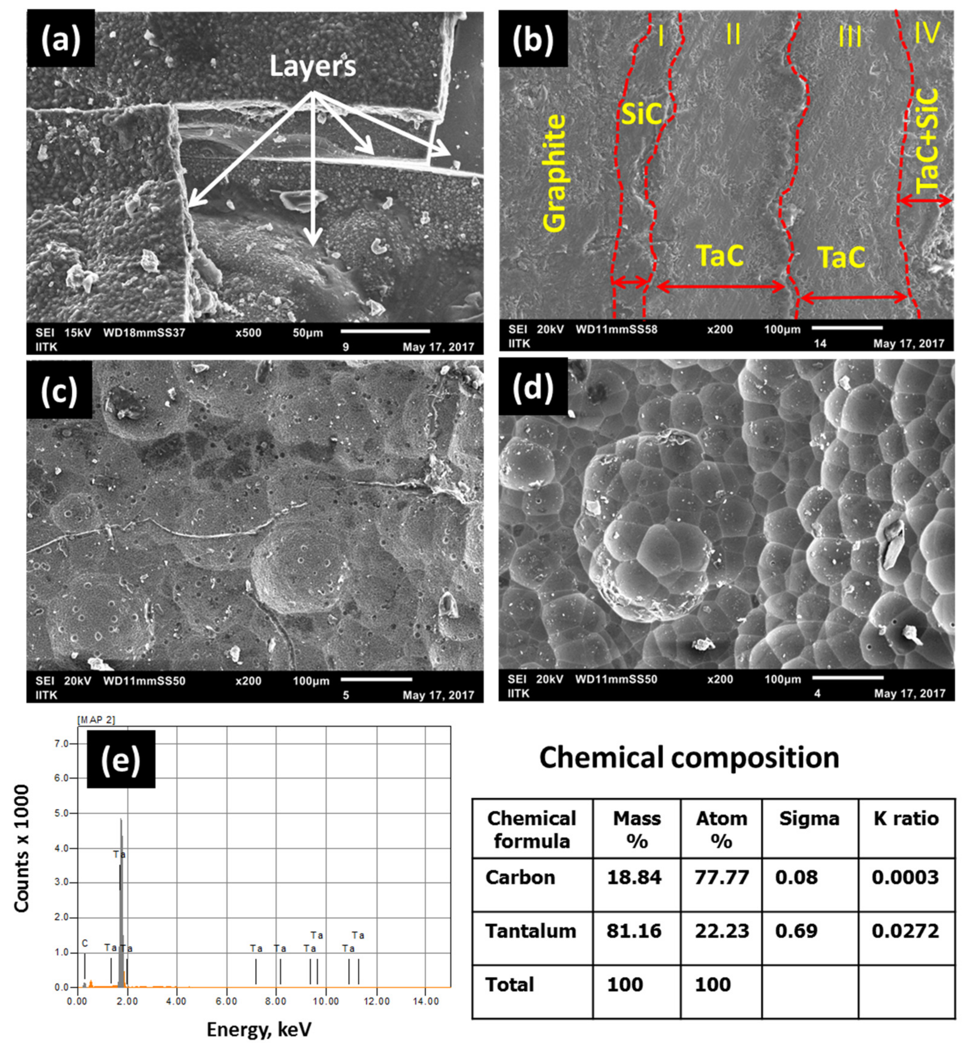
A uniform coating was observed on both tubes, but the coating thickness was different. The cumulative thickness of the coating was found to be 400 and 600 μm, respectively, at 1050 and 1150 °C. Typical images of the multilayered coating obtained are shown in Figure 2a,b. The coating thickness was built by four different layers (Figure 2a,b). The interfaces of the four layers are shown with the dotted lines (Figure 2b). Also, the substrate and outer surface of the coating are shown. The coating was found to be compact but some internal micro voids are still visible (Figure 2b). Such micro voids might have been introduced during cutting, where loosely bound particles are dispatched off under the influence of the forceful cutting forces, especially at the interface. Due to multiple interfaces, the coating is expected to tolerate thermal stresses, if any occur. Figure 2c shows the microstructures of the as-deposited TaC at 1050 °C, 100 mbar. The coating deposited at 1150 °C, 100 mbar (Figure 2d) was highly crystallized with large grains, while that deposited at 1050 °C at same pressure was found to be smoother and composed of smaller grains (Figure 2c).
The size of the grains is the resultant effect of nucleation density, effective temperature on the deposition site, concentration of the reactants, and the surface condition of the substrate. Upon increasing the coating thickness, the surface conditions change and the already grown grains affect the further desired nucleation between the existing grains. In the absence of fresh nucleation, the existing grains keep growing further and become larger. Though the nucleation density tends to increase with temperature initially, it then decreases after a critical temperature. The decreasing nucleation density beyond a critical deposition temperature is believed be due to the change in the adsorption nature from physical to chemical [15]. Also, the rate of desorption increases significantly, which results lesser sites for the new grain growth at the higher CVD temperature. The mechanism of TaC grain growth requires further studies in order to optimize the grain size vs. the ablation resistance.
Figure 2e shows the area EDAX of the coating. It is evident that the coating consists of tantalum and carbon. The coating constituents are uniformly distributed and their typical chemical composition on the surface is found to be tantalum (18.84%) and carbon (81.16%) by mass. However, EDAX analysis is very sensitive to the location and expected to show varied composition under line scan, point scan, and area scan.
For CVD, diffusion plays an important role in the rate of deposition, while the temperature and concentration of the reactant play important roles in determining the size of the grains. The rate of deposition is a function of concentration gradient, which means that at a higher partial pressure of the reactant, a higher rate of deposition would be obtained. This theory matches well with the experimental observations, as at 1150 °C and 100 mbar the rate of deposition was slightly higher. Also, the activity at higher temperatures would be high, which leads to a higher deposition rate.
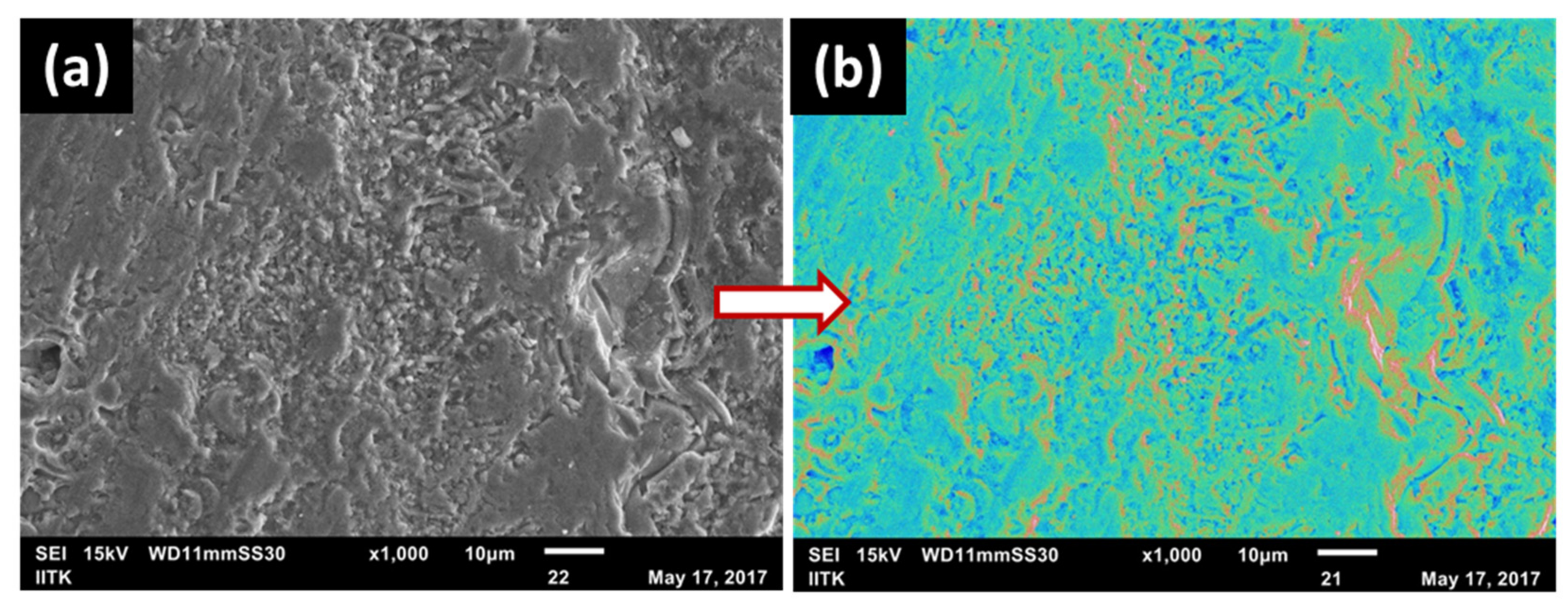
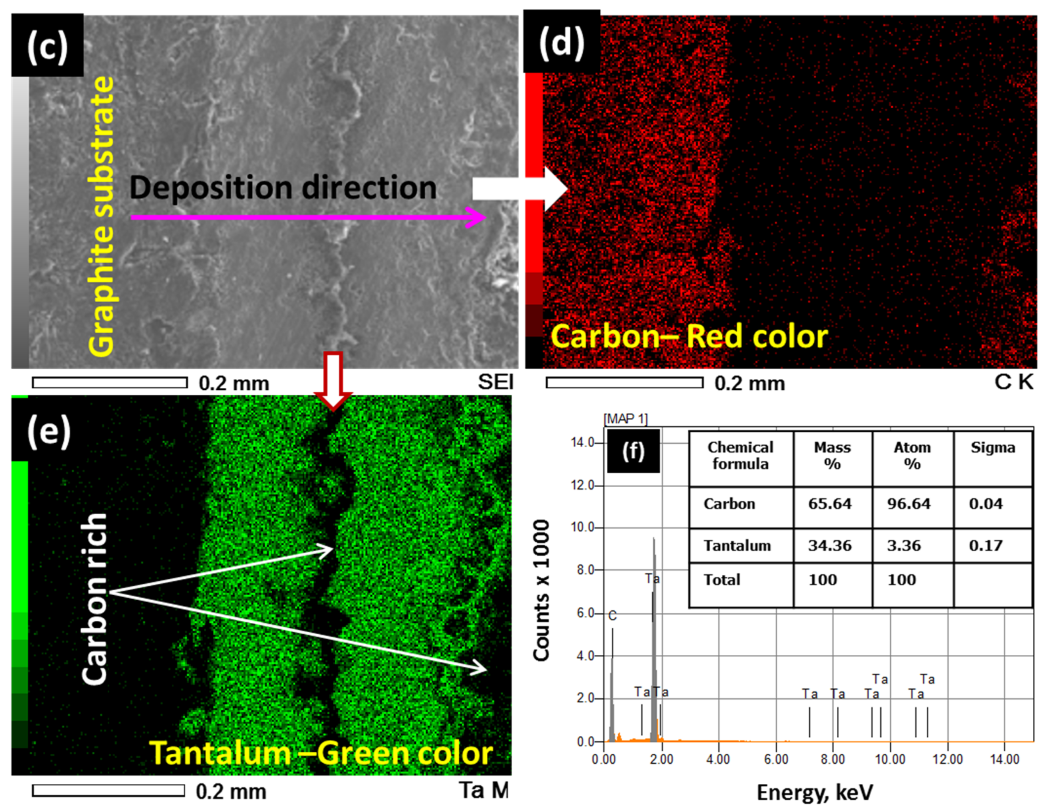
Color mapping of the chemical composition (across the thickness of the coating) shows almost uniformly light green color (Figure 3a,b), which indicates its uniformity. However, there are some other minor areas where red and blue spots are visible. This small change in the color is interpreted as other constituents such as SiC and free carbon apart from TaC. Although a TaCl5 and CH4 reaction is preferred, SiC and carbon are unavoidable as trace MTS can lead to SiC deposition, whereas the presence of CH4 can result in carbon at the reaction temperature. Figure 3c,d show the cross-sectional view of the coating and its chemical composition mapping. It is evident from Figure 3d that the coating consists mainly of carbon and tantalum constituents. However, at the interface of the TaC layers deposited at two different times, there is a distinct change in the composition which is reflected as a different color (Figure 3e). This shows that there might be some delay in the TaCl5 formation which causes its lower partial pressure compared to that of CH4. The relatively lower partial pressure of TaCl5 and higher partial pressure of CH4 results in a carbon-rich coating at the interface and a different color than the bulk coating. EDAX spectra of the image (Figure 3c) is shown as Figure 3f. It also shows that the coating is primarily composed of tantalum and carbon.
Color mapping of the chemical composition (across the thickness of the coating) shows almost uniformly light green color (Figure 3a,b), which indicates its uniformity. However, there are some other minor areas where red and blue spots are visible. This small change in the color is interpreted as other constituents such as SiC and free carbon apart from TaC. Although a TaCl5 and CH4 reaction is preferred, SiC and carbon are unavoidable as trace MTS can lead to SiC deposition, whereas the presence of CH4 can result in carbon at the reaction temperature. Figure 3c,d show the cross-sectional view of the coating and its chemical composition mapping. It is evident from Figure 3d that the coating consists mainly of carbon and tantalum constituents. However, at the interface of the TaC layers deposited at two different times, there is a distinct change in the composition which is reflected as a different color (Figure 3e). This shows that there might be some delay in the TaCl5 formation which causes its lower partial pressure compared to that of CH4. The relatively lower partial pressure of TaCl5 and higher partial pressure of CH4 results in a carbon-rich coating at the interface and a different color than the bulk coating. EDAX spectra of the image (Figure 3c) is shown as Figure 3f. It also shows that the coating is primarily composed of tantalum and carbon.
3.2. XRD and XPS Analysis of the As-Deposited Coating
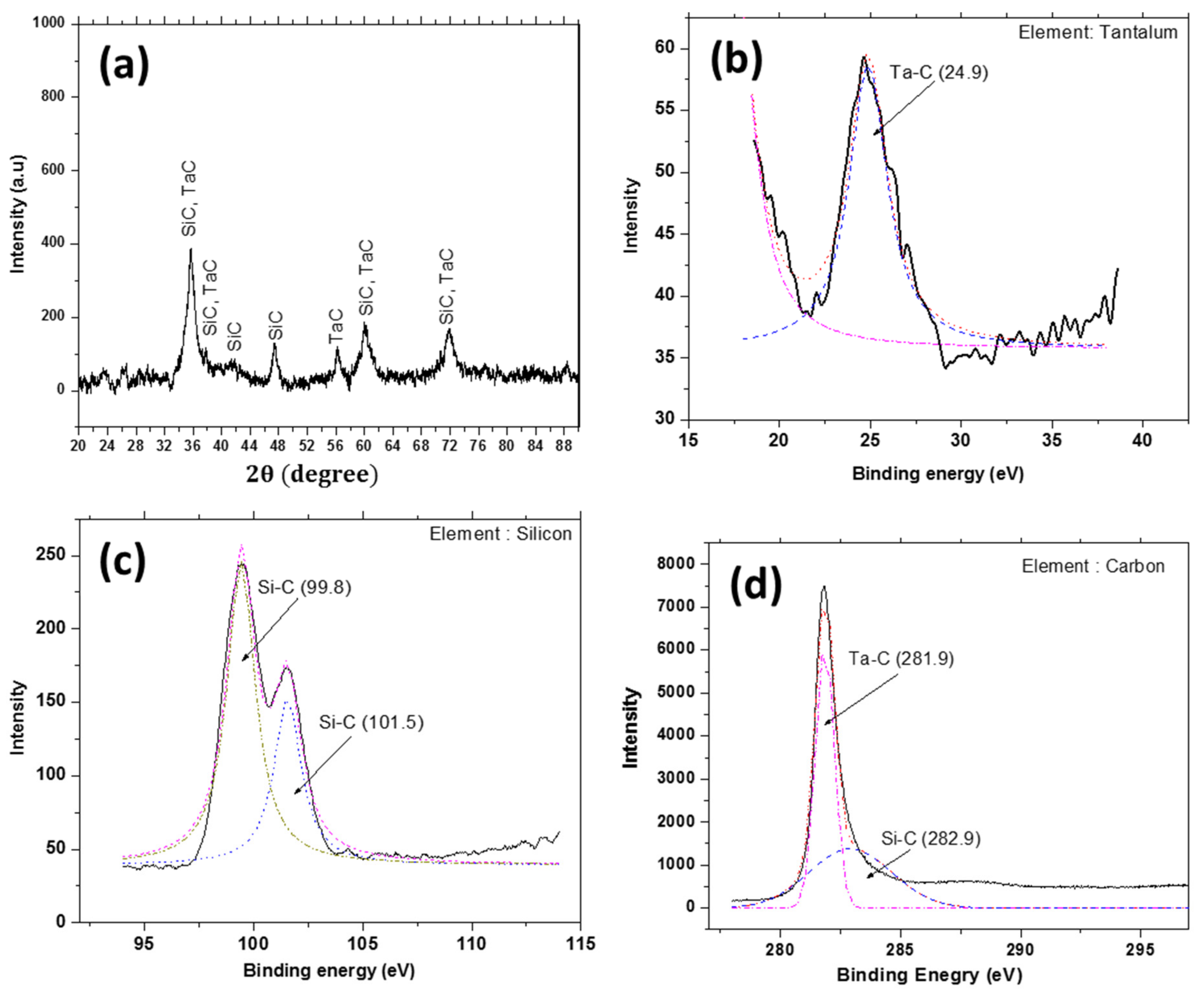
XRD pattern of the as-deposited coating is shown in Figure 4a. The peaks at 2θ = 36.36°, 38.1°, 56.28°, 59.8°, and 71.89° match well with the TaC polymorphs corresponding to the lattice planes of (002), (101), (003), (110), and (112) according to the JCPDS [74-2307], while the peak at 87.9° matches well with the tantalum carbide according to the JCPDS [02-1023]. The peaks at 2θ = 35.65°, 41.4°, 47.93°, 60.0°, and 71.77° match well with the SiC polymorphs corresponding to the lattice planes of (111), (200), (008), (220), and (311) according to the JCPDS [74-2307]. Similar peak positions for the CVD-deposited TaC are reported elsewhere [9]. The peaks of TaC and SiC are very near to each other and, in all probability, they have been superimposed onto each other. In order to obtain further clarity, XPS was carried out. XPS analyses of the coating scanned for three elements viz. tantalum, silicon, and carbon are shown in Figure 4b–d. These results show that the coating is composed of TaC and SiC. Binding peaks for tantalum element (4f5/2) with carbon are found to be at 24.9 eV (Figure 4b) [16], while the binding peaks for carbon element (1s) with tantalum and silicon are found to be at 281.9 eV [17] and at 282.9 eV, respectively [18] (Figure 4d). Meanwhile, the binding peaks for silicon element (2p) with carbon are found to be at 99.85 eV [19] and at 101.5 eV [20] (Figure 4c). The XRD and XPS data complement each other and are evident of the deposition of TaC using the in situ synthesized TaCl5. The SiC layer introduced between graphite and TaC as well as on the surface as the co-deposition of TaC + SiC is evident in the XPS studies, where SiC bonding is seen at 99.8 and 101.5 eV (Figure 4c). Close matching of the binding energies of TaC and SiC with the standards show that the deposition temperature and other deposition conditions were appropriate.
3.3. Characterization after Thermal Shock and Ablation
The coating was found to be intact after the ablation test with no apparent surface cracks due to thermal shock. There was no change in the thickness of the specimen after the ablation, but the surface of the samples was somewhat oxidized and discolored, and there was a net weight loss. Since, the coating thickness was almost the same, the weight loss is interpreted as being due to the oxidation of the graphite substrate which has two sides without coating. The samples for the ablation test were cut from the graphite tube; although the coating was thick and uniform over the tube, after cutting the samples, two newly generated sides became uncoated. The CTE of TaC ((6.7−8.2) × 10−6 K−1) was about four times larger than that of the graphite [21]. During cooling and due to the large CTE mismatch, the TaC coating shrinks in all directions whereas the graphite shrinkage is negligible. This shrinkage may develop cracks perpendicular to the coating surface. To avoid such problems, the first coating of SiC was deposited on the graphite tube substrate followed by the TaC coating. The sequence of the coatings resulted in the gradient of the CTE, which helped to keep the coating intact during the test. After the incorporation of SiC between the graphite substrate and TaC, and by building the coating thickness in stages, the coating features multiple interfaces. Due to sudden temperature change, thermal stresses may be generated which may lead to multiple cracks in the coating if the stresses exceed the strength of the coating. However, the multiple interfaces present in the coating could absorb the thermal stresses generated during the oxyacetylene test, and the coating could remain crack-free after the ablation test.
3.4. Morphology and Phase Analysis of the Ablated Specimens
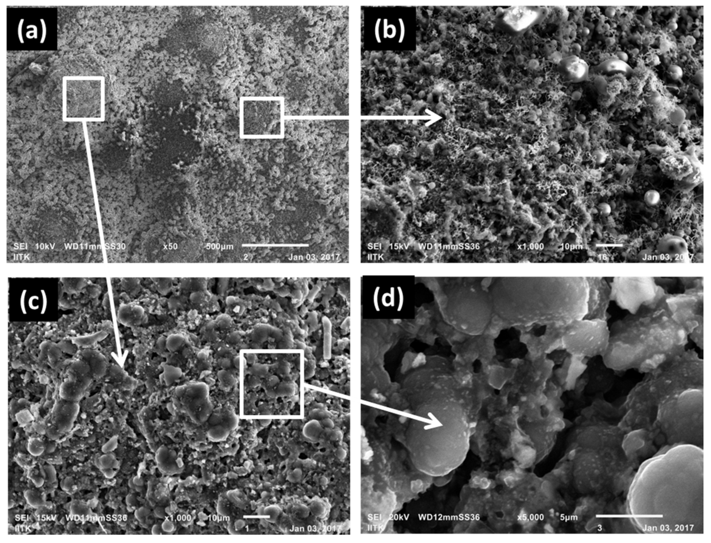
From the SEM images depicted in Figure 5a–d, it is evident that the coating surface morphology was changed after the ablation test for both test durations. The effect of the testing duration was negligible on the thickness of the coating. There are indications that some materials were melted and then formed a relatively smoother structure, as shown in Figure 5a–d. Also, spherical micro balls formed at some locations (Figure 5b). This might be due to the oxide formation of the TaC and SiC coating under high temperature oxidizing conditions [9,22].
4TaC + 9O2 = 2Ta2O5 + 4CO2
TaC + 2O2 = TaO2 + CO2
2SiC + 3O2 = 2SiO2 + 2CO
SiC + 2O2 = SiO2 + CO2
SiO2 melts around 1600 °C, whereas Ta2O5 melts around 1870 °C. During the oxyacetylene test, surface temperature can reach well above the melting points of these oxides.
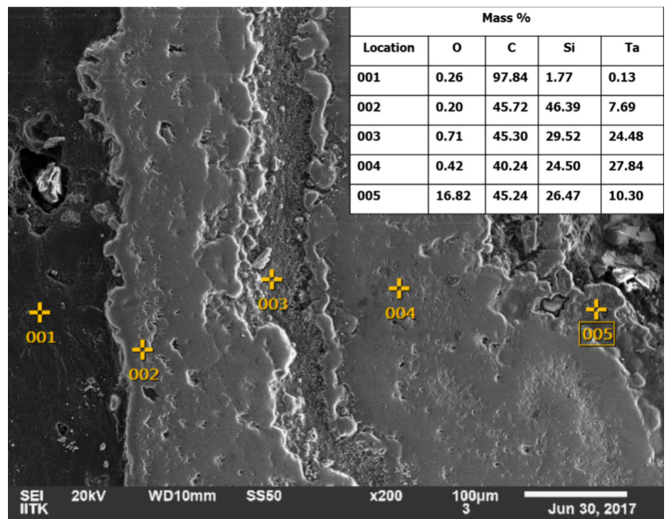
Ablation of the TaC coating under oxyacetylene flame is mainly an oxidation process at temperature above 2000 °C. Over 700 °C, TaC begins to be oxidized into Ta2O5 in the presence of air [9,12,13]. Oxidation involves the diffusion reaction of C to the outside and O to the coating interior, the movement of Ta atoms is rather small due to its heavy atomic mass, and the morphology of the TaC columnar crystal is largely inherited [9,12,13]. During the oxyacetylene test, the surface temperature of the coated sample reaches above 2000 °C and the coating oxidizes to form the fine particles of Ta2O5 crystals. In addition, the dense morphology of tantalum oxide in the Figure 5c, is interpreted due to the melting of Ta2O5-SiO2, which is in liquid phase at temperatures above 1560 °C [23]. The molten oxides form a continuous network and hinder the diffusion of oxygen. The glassy phase showed that nano-aggregates of tantalum and silicon oxide precipitate and tend to coalesce. Therefore, the coating and substrate underneath remain intact and the oxide phase continuously protects the graphite for larger durations. A variation of oxygen concentration at different locations is shown in Figure 6. At location 001 (which corresponds to the graphite), oxygen is found to be almost zero, while at the ablated surface, the oxygen concentration is found to be 16.82%. At other locations viz. 002, 003, and 004, the concentration of oxygen is less than 1.0%. This shows that the molten oxide layer at the outermost surface did not allow oxygen diffusion from the top to the substrate, and the substrate thus remained unaffected.
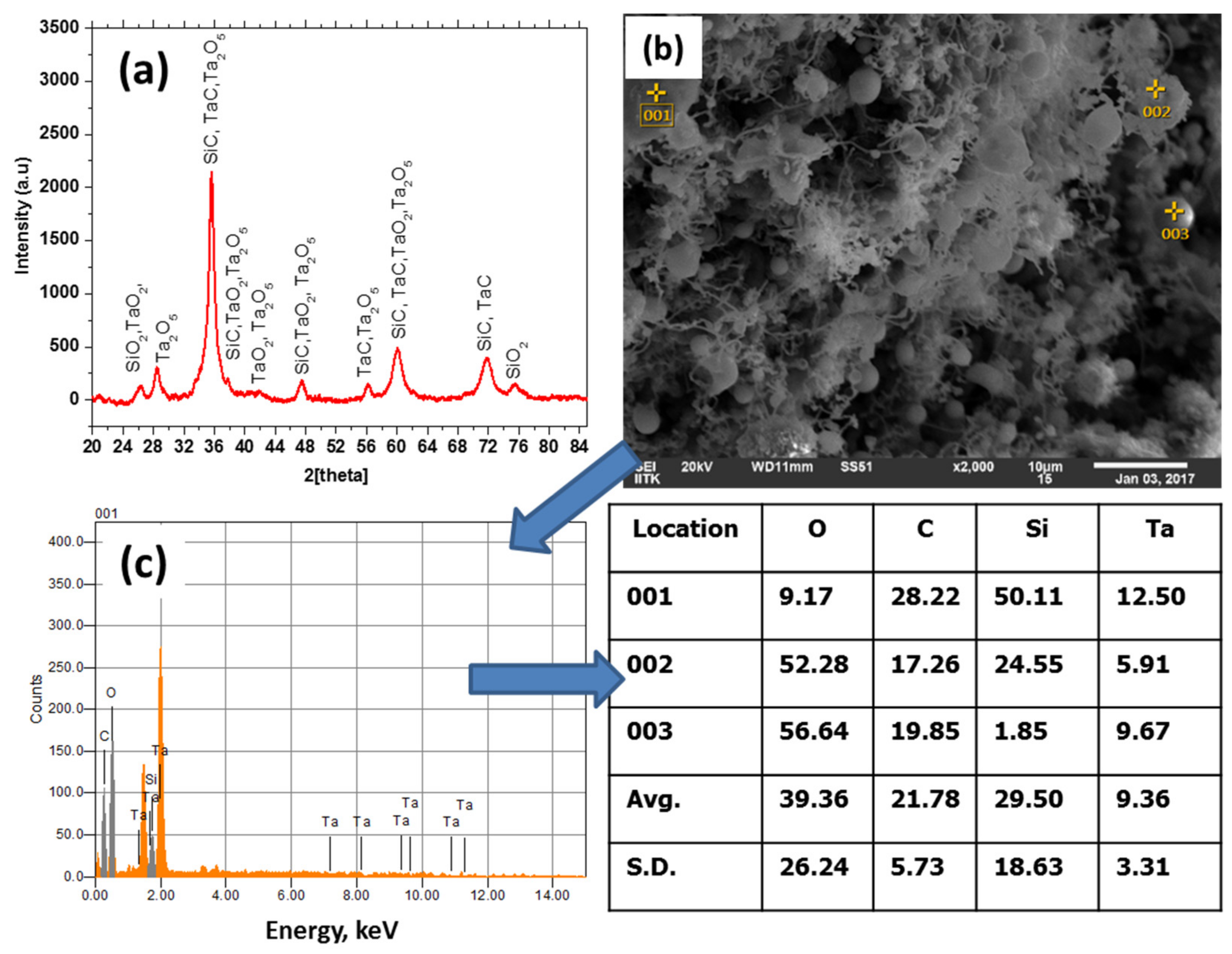
XRD and EDAX pattern of the oxyacetylene tested coating is shown in Figure 7a–d. The number of peaks is greater compared to the as-coated sample. The peaks might be due to TaC, SiC, and their oxide phases, as expected. The peaks at 2θ = 35.65°, 47.93°, 60.0°, and 71.77° match well with the polymorph of SiC corresponding to the lattice planes of (111), (008), (220), and (311) according to the JCPDS [74-2307]. The peaks at 2θ = 36.36°, 59.8°, and 71.89° match well with the TaC polymorph corresponding to the lattice planes of (002), (110), and (112) according to the JCPDS [74-2307], while there are many additional peaks compared to the as-deposited coating. These are attributed to the oxides of TaC and SiC. TaO2 peaks were identified at positions viz. 2θ = 26.74°, 34.94°, 38.19°, 42.3°, 47.0°, 50.1°, and 60.4° corresponding to the lattice planes of (400), (222), (440), (242), (123), (701), and (004), respectively, as per the JCPDS [77-2305]. Meanwhile, Ta2O5 peaks were identified at positions viz. 2θ = 28.24°, 35.6°, 38.06°, 42.3°, 47.4°, 50.04°, 56.19°, and 60.05°, corresponding to the lattice planes of (411), (16 0 1), (13 1 1), (15 0 2), (20 1 0), (213), (12 1 3), and (16 2 1), respectively, as per the JCPDS [79-1375]. Some of the peaks of SiO2 were also identified at positions viz. 2θ = 26.63°, 50.1°, and 75.64° corresponding to lattice planes of (101), (112), and (032), respectively, as per the JCPDS [86-1630]. The peaks of SiC and TaC are very near to each other and might have been superimposed onto each other. TaO2, Ta2O5, and SiO2 formation during the ablation of TaC and SiC have also been reported by others [9,12,13].
The EDAX analysis of the flame-tested sample shows that all the micro balls have elemental tantalum and silicon apart from oxygen and carbon. As expected, the point EDAX shows different chemical composition (Figure 7b–d) than the area EDAX. The oxides of SiC and TaC may melt at the oxyacetylene test temperature, but solidification of Ta2O5 and SiO2 would occur at different temperatures. Ta2O5 would solidify at around 1870 °C while SiO2 would solidify at around 1600 °C, therefore due to heterogeneity their flow might be hindered and at some places the oxides are seen as micro balls rather than the continuous homogeneous solidified ceramic layer. However, the density of such micro balls is very high and gaps between these balls are in sub-microns. They therefore create a reasonably good sealing and protecting layer against oxygen diffusion and subsequent oxidation. In some places, such micro balls are not visible; this might be due to the removal of the softened oxide phase under the oxyacetylene flame velocity. Upon a further increase in temperature, the coating might form a continuous layer and act as a perfect seal against inward oxygen diffusion.
4. Conclusions
- Chlorination of tantalum chips at ≈550 °C has resulted in the in situ synthesis of TaCl5. Based on TaCl5-CH4-Ar and CH3SiCl3-H2-Ar reactive systems, the crack-free multilayer coating of TaC and SiC is successfully developed on a graphite tube by CVD at 1050–1150 °C and 50–100 mbar. XRD and XPS studies confirm the formation of TaC and SiC.
- By depositing SiC as transition layers between the graphite and TaC, the stress concentration could be released and crack-free coating could be obtained. The coating remained intact even after the ablation test under oxyacetylene flame. At 1150 °C the thickness of the coating was about 600 μm, while at 1050 °C it was about 400 μm for the same duration and flow conditions.
- The oxyacetylene flame ablation of the TaC coating is mainly an oxidation process where surface TaC is oxidized to TaO2 and Ta2O2, while SiC oxided SiO2 and acted as protective liquid film to prevent further oxidation of the graphite underneath.
- The uniform deposition of TaC on the cylindrical graphite tube has established the process for generating a CVD coating of TaC on similar geometrical featured propulsion systems such as graphite throat inserts, as well as the chambers and nozzles of rocket motors.
Acknowledgments
The authors wish to acknowledge DRDO for funding the work. Authors also acknowledge the officers and staff of CMCD/ASL and DCCMC/DMSRDE providing experimental and characterization support to accomplish the work. The authors would like to thank Shri. Krishnakant Murya, Project Engineer for his help in SEM and XRD testing.
Author Contributions
The corresponding author, Suresh Kumar has planned and executed the CVD experiments and characterization. He has also interpreted the results and written the first draft of the manuscript. Samar Mondal assisted the corresponding author is carrying out the CVD experiments. Anil Kumar and Ashok Ranjan reviewed the first draft of the manuscripts and incorporated the necessary corrections. Namburi Eswara Prasad did the final corrections and approved the manuscript for submission in the journal.
Conflicts of Interest
The authors declare no conflict of interest.
References
- McKee, D.W. Oxidation Protection of Carbon Materials, Chemistry and Physics of Carbon; Thrower, P.A., Ed.; Marcel Dekker: New York, NY, USA, 1991; Volume 23, pp. 173–232. [Google Scholar]
- Kumar, S.; Shekar, K.C.; Jana, B.; Manocha, L.M.; Prasad, N.E. C/C and C/SiC Composites for Aerospace Applications. In Aerospace Materials and Material Technologies; Part of the series Indian Institute of Metals Series; Springer: Singapore, Singapore, 2016; pp. 343–369. [Google Scholar]
- Paul, A.; Jayaseelan, D.D.; Venugopal, S.; Zapata-Solvas, E.; Binner, J.G.P.; Vaidhyanathan, B.; Heaton, A.; Brown, P.M.; Lee, W.E. UHTC composites for hypersonic applications. Am. Ceram. Soc. Bull. 2012, 91, 22–28. [Google Scholar]
- Yang, Y.; Li, K.; Li, H. Ablation behavior of HfC coating prepared by supersonic plasma spraing for SiC-coated C/C composites. Adv. Compos. Lett. 2015, 24, 107–112. [Google Scholar]
- Hu, M.H.; Li, K.Z.; Li, H.J.; Wang, B.; Ma, H.L. Double layer ZrSi2-ZrC-SiC/SiC oxidation protective coating for carbon/ carbon composites. Surf. Eng. 2014, 31, 335–341. [Google Scholar] [CrossRef]
- Ren, X.; Li, H.; Fu, Q.; Li, K. Ultra-high temperature ceramic TaB2-TaC-SiC coating for oxidation protection of SiC-coated carbon/carbon composites. Ceram. Int. 2014, 40, 9419–9425. [Google Scholar] [CrossRef]
- Boisselier, G.; Maury, F.; Schuster, F. SiC coatings grown by liquid injection chemical vapor deposition using single source metal-organic precursors. Surf. Coat. Technol. 2013, 215, 152–160. [Google Scholar] [CrossRef]
- Chen, S.A.; Li, G.D.; Hu, H.F.; Li, Y.; Mei, M. Microstructure and properties of ablative C/ZrC-SiC composites prepared by reactive melt infiltration of zirconium and vapour silicon infiltration. Ceram. Int. 2017, 43, 3439–3442. [Google Scholar] [CrossRef]
- Li, G.-D.; Xiong, X.; Huang, K.-L. Ablation mechanism of TaC coating fabricated by chemical vapor deposition on carbon-carbon composites. Trans. Nonferr. Met. Soc. China 2009, 19, s689–s695. [Google Scholar] [CrossRef]
- Dua, A.K.; George, V.C. TaC coatings prepared by hot filament chemical vapour deposition: Characterization and properties. Thin Solid Films 1994, 247, 34–38. [Google Scholar] [CrossRef]
- Bruno, T.S.; Anthony, C.; Paul, Y.; Sanjay, B.; Paul, J.; Lynn, D.; Joseph, Z. Net Mold Tantalum Carbide Rocket Nozzle Throat. U.S. Patent 6,673,449, 6 January 2004. [Google Scholar]
- Li, G.D.; Xiong, X.; Huang, B.-Y. Microstructure characteristic and formation mechanism of crack-free TaC coating on C/C composite. Trans. Nonferr. Met. Soc. China 2005, 15, 1206–1213. [Google Scholar]
- Li, G.D.; Xiong, X.; Huang, B.-Y.; Huang, K.-L. Structural characteristics and formation mechanisms of crack-free multilayer TaC/SiC coatings on carbon-carbon composites. Trans. Nonferr. Met. Soc. China 2008, 18, 255–261. [Google Scholar] [CrossRef]
- Verdon, C.; Szwedek, O.; Jacques, S.; Allemand, A.; Le Petitcorps, Y. Hafnium and silicon carbide multilayer coatings for the protection of carbon composites. Surf. Coat. Technol. 2013, 230, 124–129. [Google Scholar] [CrossRef]
- Yasuaki, H.; William, D.; Russel, M. Temperature dependence of nucleation density of chemical vapor deposition diamond. Jpn. J. Appl. Phys. 1992, 31, L193–L196. [Google Scholar]
- Khyzhun, O.Y.; Sinelnichenko, A.K.; Kolyagin, V.A. NIST XPS Database. Available online: https://srdata.nist.gov/xps/XPSDetailPage.aspx?AllDataNo=94091 (accessed on 15 June 2017).
- Ramqvist, L. Charge transfer in transition metal carbides and related compounds studied by ESCAJ. Phys. Chem. Solids 1969, 30, 1835. [Google Scholar] [CrossRef]
- Galuska, A.A.; Uht, J.C.; Marquez, N. Reactive and nonreactive ion mixing of Ti films on carbon substrates. J. Vac. Sci. Technol. 1988, A6, 110–122. [Google Scholar] [CrossRef]
- Aoyama, T.; Sugil, T.; Ito, T. Determination of band line-up in β-SiC/Si hetero-junction for Si-HBT’s. Appl. Surf. Sci. 1989, 41, 584–586. [Google Scholar]
- Niles, D.W.; Hochst, H.; Zajac, G.W.; Fleisch, T.H.; Johnson, B.C.; Meese, J.M. The interface formation and thermal stability of Ag overlayers grown on cubic SiC (100). J. Vac. Sci. Technol. 1988, A6, 1584–1588. [Google Scholar] [CrossRef]
- Mag-isa, A.E.; Kim, J.-H.; Oh, C.-S. Measurements of the in-plane coefficient of thermal expansion of free standing single-crystal natural graphite. Mater. Lett. 2016, 171, 312–331. [Google Scholar] [CrossRef]
- Lespade, P.; Richet, N.; Goursat, P. Oxidation resistance of HfB2-SiC composites for protection of carbon-based materials. Acta Astronaut. 2007, 60, 858–864. [Google Scholar] [CrossRef]
- Pienti, L.; Sciti, D.; Silvestroni, L.; Cecere, A.; Savino, R. Ablation tests on HfC- and TaC-based ceramics for aeropropulsive applications. J. Eur. Ceram. Soc. 2015, 35, 1401–1411. [Google Scholar] [CrossRef]
Figure 1.
Typical scheme of the TaC deposition unit: (a) in situ chlorination device; (b) CVD reactor.
Figure 1.
Typical scheme of the TaC deposition unit: (a) in situ chlorination device; (b) CVD reactor.
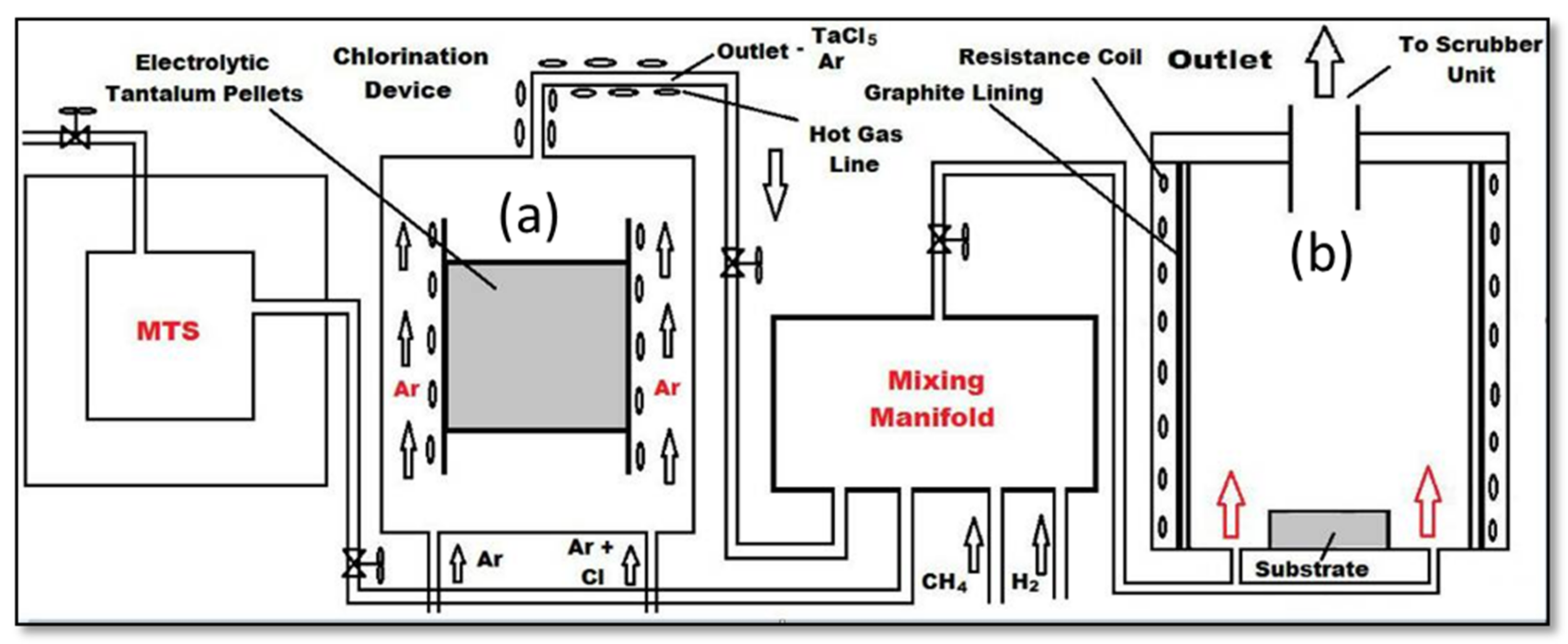
Figure 2.
As-deposited TaC coating surface morphology and Energy Dispersive X-ray Spectroscopy (EDAX) analysis: (a) Optical image of the coated sample which shows the four layers; (b) SEM image to show through-thickness coating layers; (c) coating mophology at 1050 °C, 100 mbar; (d) coating mophology at 1150 °C, 100 mbar; (e) Energy Dispersive X-ray Spectroscopy spectra of the as-deposited TaC layer.

Figure 3.
EDAX mapping and composition analysis of as-deposited coating across the thickness: (a) medium magnificantion TaC coating cross-section; (b) chemical composition mapping through color of Figure 3a; (c) low magnificantion SEM image of cross-section of the coating; (d) carbon composition mapping through color of Figure 3c; (e) tantalum composition mapping through color of Figure 3c; (e) area EDAX spectra of Figure 3c.


Figure 4.
XRD and XPS analysis of as-deposited coating: (a) XRD spectra after the deposition of four layers; (b) XPS spectra of TaC binding energy; (c) XPS spectra of SiC binding energy; (d) XPS spectra of carbon binding energy with Ta and carbon.
Figure 4.
XRD and XPS analysis of as-deposited coating: (a) XRD spectra after the deposition of four layers; (b) XPS spectra of TaC binding energy; (c) XPS spectra of SiC binding energy; (d) XPS spectra of carbon binding energy with Ta and carbon.

Figure 5.
Surface morphology of the ablated specimens: (a) SEM image of the as-ablated specimen; (b,c) magnified image at two different locations showing different surface morphologies; (d) solidified network of the molten oxide phases of TaC and SiC.
Figure 5.
Surface morphology of the ablated specimens: (a) SEM image of the as-ablated specimen; (b,c) magnified image at two different locations showing different surface morphologies; (d) solidified network of the molten oxide phases of TaC and SiC.

Figure 6.
Along the thickness chemical composition of the coating after the ablation test.

Figure 7.
XRD and EDAX analysis of the ablated surface: (a) XRD spectra of the surface of the coating after the oxyacetylene test; (b) typical SEM image of the ablated surface; (c) EDAX spectra of the specific points at the ablated surface.
Figure 7.
XRD and EDAX analysis of the ablated surface: (a) XRD spectra of the surface of the coating after the oxyacetylene test; (b) typical SEM image of the ablated surface; (c) EDAX spectra of the specific points at the ablated surface.

© 2017 by the authors. Licensee MDPI, Basel, Switzerland. This article is an open access article distributed under the terms and conditions of the Creative Commons Attribution (CC BY) license (http://creativecommons.org/licenses/by/4.0/).
Share and Cite
MDPI and ACS Style
Kumar, S.; Mondal, S.; Kumar, A.; Ranjan, A.; Prasad, N.E. Chemical Vapor Deposition of TaC/SiC on Graphite Tube and Its Ablation and Microstructure Studies. Coatings 2017, 7, 101. https://doi.org/10.3390/coatings7070101
AMA Style
Kumar S, Mondal S, Kumar A, Ranjan A, Prasad NE. Chemical Vapor Deposition of TaC/SiC on Graphite Tube and Its Ablation and Microstructure Studies. Coatings. 2017; 7(7):101. https://doi.org/10.3390/coatings7070101
Chicago/Turabian StyleKumar, Suresh, Samar Mondal, Anil Kumar, Ashok Ranjan, and Namburi Eswara Prasad. 2017. "Chemical Vapor Deposition of TaC/SiC on Graphite Tube and Its Ablation and Microstructure Studies" Coatings 7, no. 7: 101. https://doi.org/10.3390/coatings7070101
Note that from the first issue of 2016, this journal uses article numbers instead of page numbers. See further details here.