Influence of Process Parameters on High Velocity Oxy-Fuel Sprayed Cr3C2-25%NiCr Coatings
by
Mingxiang Xie
1,2, 
Yue Lin
2,
Peng Ke
2,3,
Shuoyu Wang
1,
Shihong Zhang
2,3,*,
Zhicheng Zhen
1 and
Liangshui Ge
1 1
Maanshan Ma Steel Surface Engineering Technology Co. Ltd., Maanshan 243000, China
2
Research Center of Modern Surface & Interface Engineering, Anhui University of Technology, Maanshan 243002, China
3
School of Materials Science and Engineering, Anhui University of Technology, Maanshan 243002, China
*
Author to whom correspondence should be addressed.
Coatings 2017, 7(7), 98; https://doi.org/10.3390/coatings7070098
Submission received: 14 April 2017
/
Revised: 26 June 2017
/
Accepted: 27 June 2017
/
Published: 9 July 2017
(This article belongs to the Special Issue Thermal Spray Technology)
Abstract
:In this work, the Cr3C2-25% NiCr powder was deposited on stainless steel with different combustion pressures and powder feed rates using HVOF technique. The microstructure, porosity, micro-hardness, indentation fracture toughness, adhesion strength, and wear resistance at 500 °C of the coatings were investigated. The results showed that HVOF sprayed Cr3C2-25% NiCr coatings possessed low porosity, high micro-hardness, and enough adhesion strength. The powder feed rate had obvious effect on porosity, micro-hardness and indention fracture toughness of the coatings, and the coating sprayed under the powder feed rate of 33.5 g/min possessed the optimal performance. The wear tests illustrated that the HVOF sprayed Cr3C2-25NiCr coating possessed good wear resistance at the temperature of 500 °C, in which the coating sprayed at the powder feed rate of 33.5 g/min had the best wear resistance due to its dense structure and enough fracture toughness.
1. Introduction
Cermet coatings are widely used in industrial applications against tribological degradation even in the corroding environment, due to their high hardness and good corrosion resistance of the employed metal matrices. Chromium carbide-based materials are generally employed to produce hard coatings for high temperature wear applications including sliding, fretting, abrasion, and erosion in powder generation industry, aerospace industry, oil-refining industry, heat-treatment rolls, and coal burning boiler tubes [1,2]. The chromium carbides–nickel chromium (Cr3C2-NiCr) cermet coatings have been widely practiced in industry, caused by the advantageous combination of Cr3C2 ceramic phase with good wear-resistance and NiCr metal phase which provides high oxidation resistance to high temperature [3,4]. The process of high velocity oxygen fuel (HVOF) spray turns out to be the most promising process, which means it is preferable to deposit cermet coatings such as Cr3C2-NiCr and WC–Co. This technique combines high velocity powder particles with low temperature to build up a dense and tightly adherent coating with low oxidation and residual stress [5]. Coatings deposited by the HVOF process exhibit high density, low porosity, excellent adhesive strength with much more carbide particles retained in the matrix compared with those deposited by plasma spraying process. It has been reported that HVOF-sprayed Cr3C2-NiCr coatings exhibit good wear resistance and corrosion resistance in various high-temperature environments [6,7,8,9].
Many researchers reported that the performance and microstructure of cermet coatings was dominantly influenced by the spray conditions [10]. Research of Qun Wang et al. [11] illustrated that change of the spraying parameters showed little effect on the phase composition of the WC–12 Co coatings but had a great influence on other performances such as hardness, porosity, fracture toughness, and the per-pass thickness of coatings. It also concluded that the sequences of importance of spray parameters on the performances of coatings are as follows: kerosene flux > spray distance > feed rate > oxygen flux for hardness; spray distance > kerosene flux > feed rate > oxygen flux for porosity; oxygen flux > kerosene flux > feed rate > spray distance for fracture toughness; and feed rate > spray distance > oxygen flux > kerosene flux for per-pass thickness. H. Fukutome etc. [12] studied the effect of low ratio of oxygen to propene on phase and abrasive wear of HVOF Cr3C2-20% NiCr coating and concluded that the best wear performance could be obtained when the flow ratio approached the chemical ratio, above which the Cr2O3 would exist.
It has been reported that the hardness, fracture toughness of the matrix, reinforcements, as well as the interfacial strength of reinforcement/matrix are the most important mechanical factors that determine the wear resistance and failure properties of cermet-based coatings [13]. The effect of fracture toughness on coating wear performance was investigated widely. High fracture toughness was beneficial to wear resistance of coatings [14]. While Gang-Chang Ji [15] reported the removal of carbide particles in the coating was mainly responsible for the abrasive wear of the coating. The content and particle size of the Cr3C2 carbides were the two key factors controlling the abrasive wear of the HVOF sprayed Cr3C2-NiCr coatings [15,16].
In the present work, three types of Cr3C2-25NiCr coatings deposited by HVOF were sprayed under different powder feed rate using WOKAStar 640 system (Sulzer Metco, Winterthur, Switzerland). All the coatings were characterized by X-ray diffraction (XRD), optical microscope, image analyzer, scanning electron microscope (SEM) including energy dispersive spectroscopy (EDS), micro-hardness tester, and nano-indenter. The wear resistance and wear mechanisms of Cr3C2-25NiCr coatings at 500 °C were researched and analyzed.
2. Experimental Procedures
2.1. Preparation of Coatings
The Cr3C2-25%NiCr feedstock powders of spherical shape and a grain size of 20–50 µm were coated onto 304 stainless steel substrates. Three kinds of coatings were obtained by HVOF and the spraying parameters were listed as Table 1. The WOKAStar-640 HVOF system based on liquid fuel (Kerosene of aviation grade) was used to obtain the coating sheet. The powder was axial feed by nitrogen. Prior to spraying, the stainless steel disks at the size of 100 mm × 30 mm × 10 mm were grit-blasted with alumina to achieve an average surface roughness (Ra) of about 5.0 μm and then cleaned in an ultrasonic bath of acetone so as to enhance the adhesion strength between the coatings and substrate. The thickness of the as-sprayed coatings was about 150 μm.
2.2. Wear Test at 500 °C
The wear performance of the coated samples (dimensions: 15 mm × 15 mm × 10 mm) was tested using ball-on-disk (BOD) high-temperature wear tester (Model: HT 1000, Zhongke Kaihua, Lanzhou, China). Prior to the test, the coated samples were polished and then cleaned ultrasonically with acetone and alcohol. The coated samples were mounted firmly in the sample holder and were allowed to be pressed against the rim of the rubber wheel with desired normal force by applying a known dead weight (20 N). The test was performed under 500 °C for 3600 s to obtain the friction coefficient of the coatings. The wear counterpart was the WC ball, whose diameter was 6 mm. The wear rate of the coatings was measured by volume wear loss, which was tested by the apparatus of step profiler (Model: KLA-Tencor P7, KLA-Tencor, Silicon Valley, CA, USA).
2.3. Characterization of Cr3C2-25NiCr Coatings and Worn Surface
After HOVF spraying, the samples were cut into the dimensions of 12 mm × 12 mm × 10 mm and again cleaned ultrasonically with acetone and alcohol again. The cross-sectional micrograph of coatings was obtained by optical microscopy and scanning electron microscopy (SEM). The worn surface of the coatings was also analyzed by SEM/EDS and surface profiler. Porosity was obtained by using an image tool. For each sample, the mean value of the eight readings was calculated for measuring the porosity. X-ray diffraction (XRD) analysis of the coating was done on the surface by Bruker-08A diffractometer (Bruker, Karlsruhe, Germany). It is operated at 40 kV and 40 mA, using Cu-Kα as radiation. The bond strength of coatings was tested according to ASTM adhesion test standard [17]. The micro-hardness of the as-sprayed coatings was measured by an HV-432 micro-hardness tester (Wilson, Norwood, CO, USA) at a load of 1 kg and for a loading duration of 10 s. The average value of the five readings for each specimen was calculated. Indentation fracture of coating toughness was tested by indentation apparatus of Vickers indenter (Model: VH 1150, Wilson, Norwood, CO, USA). The indentation was carried out on the cross-section of the coatings in the mid-plane region to minimize the edge and interface effect. The indenter was loaded so that one of the horizontal diagonals was parallel to the interface of the coating and substrates. A load of 2 kg was applied for a dwell time of 20 s at a fixed rate. Nano-indention test was conducted on the surface of coating using G200 Nano-indenter (Agilent, California, CA, USA). For each sample, 15 readings were obtained on polished surface using the same parameter, and the indention was obtained by VHX-900 microscope (KEYENCE, Tokyo, Japan). Meanwhile, the unload-to-load curve was obtained.
3. Results and Discussion
3.1. Phase Structures of Powder and Coatings
The XRD patterns of Cr3C2-25NiCr powder and three coatings were showed in Figure 1. Peaks of carbides (Cr3C2) and binder phase (NiCr) were observed both in the powder and coatings. The carbides phase of Cr7C3 was found in the coating, which was formed by the decarburization of Cr3C2. In the comparison of powder and coatings, there was a very broad peak centered round 43° in the pattern of coatings. All peaks of nickel solid solution and Cr3C2 become broad, and a very broad peak centered at around 43° appeared in the as-sprayed condition of three coatings. The very broad peak indicated the formation of an amorphous phase due to the high cooling speed of HVOF process. Therefore, it was indicated that nickel–chromium alloy and some Cr3C2 carbide were melt and some amorphous phase formed. The similar results were also reported in those previous studies [18,19]. Mohanty et al. [20] observed the transformation of Cr3C2 phase to Cr23C6 phase while spraying Cr3C2-NiCr powder by Jet Kote technique. However, this transformation was not found in this study. One possible reason was that the residence time of the particles in the flame was much less for the spraying system with liquid fuel. Three XRD patterns of coatings were nearly the same and showed little decarburization of Cr3C2, which indicated little effect of spraying parameters on coating phase structure. By calculating the ratio of Cr3C2 to Cr7C3 of coating-A, coating-B, coating-C was 1.61, 1.85, 1.53, respectively. It illustrated the coating-B possessed more Cr3C2 phase, which meant relatively small decarburization of Cr3C2 into Cr7C3 of the coating-B. It has been reported that Cr3C2 and binder NiCr were the major phases of HVOF sprayed chromium carbide-based coating, and the decarburization of Cr3C2 into Cr7C3 or Cr23C6 did not have the detrimental effect on wear resistance of the coatings [21].
3.2. Cross-Sections of Cr3C2-25NiCr Coatings
The cross-sectional SEM micrographs of three coatings were presented in Figure 2. The micrographs showed that the three coatings had similar porous microstructure and the chromium carbide particles were surrounded by the matrix phase in the coatings. The thickness of the coatings is about 150 μm. No cracks can be seen on the cross-sections of the coatings. It is reported that there are two types of pore in HVOF sprayed coating. One is striated and the other is distributed uniformly throughout the coating [22]. Similar pores could also be found in the present research. The coatings had dense structure and carbides distributed uniformly in the coating. It could be found that the coating-B was more dense and uniform than others, which was the least porous of the three coatings.
The coating porosity is an important issue in thermal spraying technique as it relates to numerous coating mechanical properties [23]. The metallographic analysis of the coatings shows a low porosity. As is showed in Table 2, HVOF sprayed Cr3C2-25NiCr coatings possess low porosity values (about 1.0%). It reflects that coating-B possesses the lowest porosity among the three coatings. It is reported that the HVOF process exhibits the lowest porosity caused by its high impact velocity compared with other spraying techniques such as electric arc, flame, plasma spraying, and detonation gun.
3.3. Mechanical Properties
The micro-hardness values of the coatings are given in Table 2. The results show HVOF sprayed Cr3C2-25NiCr coating exhibits high micro-hardness (about 800 HV). In common, high hardness is of benefit to wear resistance because the hard carbide could offset external stress effectively.
Adhesive strength is one of the most important factors in thermal spray coating since it directly relates to the durability of the coating [24]. The adhesion of coating to the substrate was investigated by the tensile test. As Table 2 shows, the adhesion strength of HVOF sprayed Cr3C2-25NiCr coating could achieve more than 60 MPa. The coatings show better adhesive performance, possibly because the particle was firmly embedded in the substrate at high velocity by using HVOF spraying and the residual compressive stress could also be a reason. It has been reported that higher adhesion strength (>80 MPa) of coatings could be obtained in both the HVOF and the HVAF systems [25].
As Table 1 shows, the combustion pressure and flow of fuel are very close and the spraying parameters of the three coatings are mainly different in the powder feed rate. The ratio of the combustion pressure to the flow of fuel is 0.417 for all the coatings. Therefore, it is necessary to analyze the effect of powder feed rate on coating properties.
Figure 3 shows the effect of powder feed rate on coating properties. As the Figure 3 shows, it could be concluded that the powder feed rate has a great impact on porosity, adhesion strength, and fracture toughness of coating. With the feed rate decreasing, the molten degree of spray particles increased, which resulted in the increase of hardness and the decrease of porosity. Meanwhile, the total particles deposited on the substrate decreased and it resulted in the decrease of the per-pass thickness [11]. So, in the present study, the coating deposited at a powder feed rate of 33.7 g/min possesses optimal basic properties.
Figure 4 shows the typical indentations on transverse section with in-plane cracks for the three coatings, respectively. Due to the characteristics of thermally sprayed coatings, the cracks parallel to the coating–substrate interface are easier to be formed in comparison with those in the perpendicular direction [26]. It results from the elongated nature of the splats and the residual stress fields presented [20]. The length of crack c, from the center to the indent, was used for determining the fracture toughness of the coatings. The fracture toughness, KIC, was calculated through the following equations [13]:
where HV is the Vickers hardness, E is the Young’s modulus, d is the half-diagonal of the Vickers indentation. The radial crack length a, is equal to c, the indentation crack length minus d, the half diagonal of the Vickers indentation. Both the crack length and Vickers diagonal were measured from the optical images. Young’s modulus of the coating was measured by nano-indenter. Five readings were tested for each sample and the average fracture toughness values of the coatings are given in Table 3. The fracture toughness of the three Cr3C2-25NiCr coatings is 4.12 MPa·m1/2, 5.58 MPa·m1/2, 4.86 MPa·m1/2, respectively. It has been reported that the scatter of fracture toughness was also observed in HVOF sprayed coating, which indicated the micro-structural features of non-homogeneous coating [26]. The scatter was also found in this work and the result showed that coating-B had higher fracture toughness compared with the other coatings, which may be attributed to its lowest porosity.
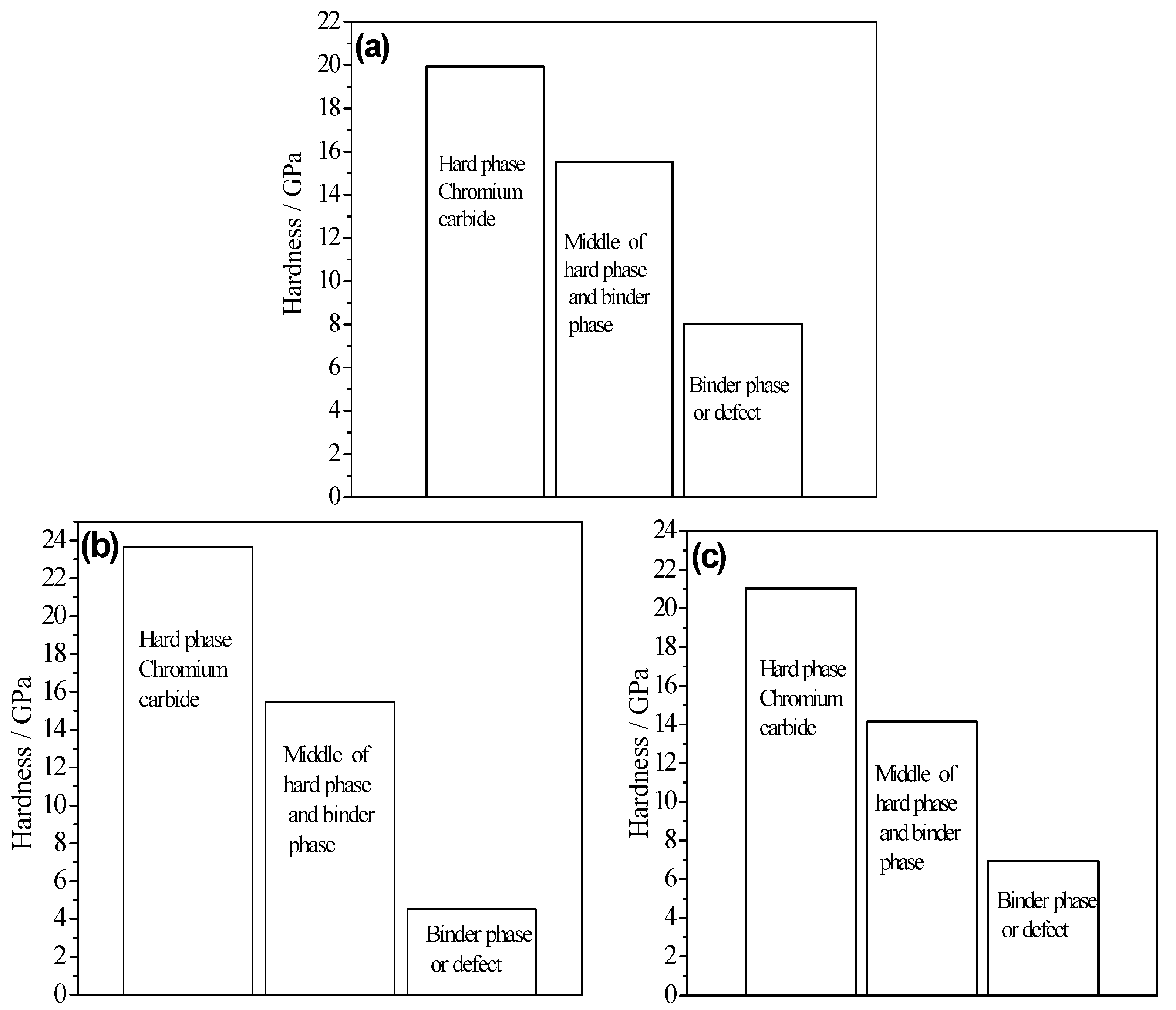
The classification of nano-indentation readings on coatings was given in Figure 5. There are three possibilities of nano-indenter pressed into the surface, namely hard phase, middle zone between hard phase and binder phase, binder phase or defect. The micrographs of nano-indentation showed these three possibilities, which showed larger indentation successively. As Figure 6 shows, there are hard phase of higher hardness and smaller indentation on binder phase and less defects in coating-B, which demonstrates a dense structure with few defects and more hard carbide contents.
In addition, special interest is given to the unload-to-load-ratio of nano-indentation, which represents the ratio between the total work (Wt) done and the recovered (elastic) work during indentation [27]. It can separate the indentation work into elastic (We) and plastic components (Wp) since Wt = Wp + We [28]. The determination of We/Wt ratio is straightforward from the load–unload curves, no need for any model application. The ratio cannot be affected by the shape of stylus, the state of material (bulk or thin film), or the applied load which generally are critical for the estimation of hardness and elastic modulus [29]. In the present, the average value of the We/Wt of the three coatings was obtained by calculating 15 curves. The result showed the We/Wt of the three coatings is 0.28, 0.43, 0.32, respectively. It illustrates that the coating B possesses higher elasticity, which could be an advantage to improve the resistance against the deformation and the mechanical properties.
3.4. Wear Performance of Coatings
Figure 6 provided the morphology of cross section of the wear scar tested by the step profile. The wear rate was calculated according to Equation (3):
where S is the area of cross section of wear scar, L is the load (N), n is the revolutions. The wear rate of the three coatings is shown in Table 3. The coating B has higher wear resistance than the others, drawing this conclusion from its lower volume loss after tests. Coating-B possesses the best wear resistance because of the dense structure, more hard carbide, high fracture toughness, and good elasticity. Those factors are all beneficial to the coating resistance against repeated external force.
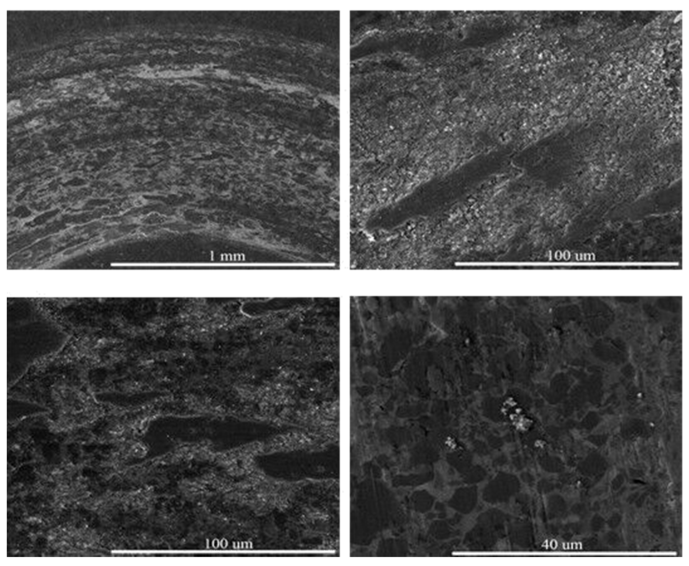
The coating-B was selected to analyze the wear mechanism of HVOF sprayed Cr3C2-25NiCr coating (see in Figure 7). There is little peeling, crack, and deformation on the worn surface. The scratches resulting from the action of abrasive particle and the particle can be clearly recognized through a close inspection. For the Cr3C2-NiCr coating, individual splat in the coating can be considered as composites in which NiCr alloy is a continuous matrix phase with chromium carbides as reinforcement hard phases. Owing to the microhardness of chromium carbides being much higher than that of NiCr matrix, the carbides are more resistant to cutting or gouging than matrix alloy phase. Accordingly, the carbide phase with higher wear resistance would be removed at a lower rate, and the wearing off of NiCr alloy binder occurs more preferentially. During the process of wearing, the high hardness of surface protuberance of WC ball could insert into the as-tested coating surface, leading to the removal of metal binder-NiCr alloy and the exposed Cr3C2 ceramic particles. Then, the exposed Cr3C2 particles suffered from shear removal because of the high-contact stress and cyclic stress, resulting from the reciprocating vibration and sliding wear process. As a result, the detached wear debris containing hard particles from the coatings and WC balls acted as abrasive particles, resulting in severe three-body abrasive wear at high temperature. The examination of worn surface morphology suggested that the abrasive wear behavior of the HVOF sprayed Cr3C2-NiCr coating was dominated by the selective gouging or cutting of NiCr binder matrix phase followed by the removal of carbide particles.
4. Conclusions
- HVOF sprayed chromium carbide-based coating possessed low porosity, high micro-hardness, and high adhesion strength.
- Powder feed rate had obvious effect on coating surface and mechanical properties (porosity, micro-hardness, and indention fracture toughness). The coating sprayed at 33.5 g/min possessed relative lower porosity, higher fracture toughness, and better elasticity. Thus, the HVOF sprayed Cr3C2-NiCr coating using WOKAStar 640 system (Sulzer Metco, Winterthur, Switzerland) had an appropriate powder feed rate of 33.5 g/min.
- The wear tests illustrated the HVOF sprayed Cr3C2-25NiCr coatings possessed good wear resistance at high temperature, which resulted from the stable friction coefficient and little peeling, crack, and deformation on the worn surface. The coating at the powder feed rate of 33.5 g/min had the best wear resistance due to the dense structure and enough fracture toughness.
Acknowledgments
This work was supported by the National Science Foundation of China (Grant no. 51671002) and the Key Technology Program of Anhui Province (Grant no. 2015kj148).
Author Contributions
Mingxiang Xie, Shihong Zhang and Yue Lin conceived and designed the experiments; Mingxiang Xie, Peng Ke and Yue Lin performed the experiments; Mingxiang Xie, Yue Lin and Peng Ke analyzed the data; Shuoyu Wang, Liangshui Ge and Zhicheng Zheng contributed reagents/materials/analysis tools.
Conflicts of Interest
The authors declare no conflict of interest.
References
- Kaur, M.; Singh, H.; Prakash, S. High-temperature corrosion studies of HVOF-sprayed Cr3C2-NiCr coating on SAE-347H boiler steel. J. Therm. Spray Technol. 2009, 18, 619–632. [Google Scholar] [CrossRef]
- He, J.H.; Ice, M.; Schoenung, J.M.; Shin, D.H.; Lavernia, E.J. Thermal stability of nanostructured Cr3C2-NiCr coatings. J. Therm. Spray Technol. 2001, 10, 293–300. [Google Scholar] [CrossRef]
- Zhang, Z.Y.; Lu, X.C.; Luo, H.B. Tribological properties of rare earth oxide added Cr3C2-NiCr coatings. Appl. Surf. Sci. 2007, 253, 4377–4385. [Google Scholar] [CrossRef]
- Li, C.J.; Ji, G.C.; Wang, Y.Y.; Sonoya, K. Dominant effect of carbide rebounding on the carbon loss during high velocity oxy-fuel spraying of Cr3C2-NiCr. Thin Solid Films 2002, 419, 137–143. [Google Scholar] [CrossRef]
- Magnani, M.; Suegama, P.H.; Espallargas, N. Influence of HVOF parameters on the corrosion and wear resistance of WC-Co coatings sprayed on AA7050 T7. Surf. Coat. Technol. 2008, 202, 4746–4757. [Google Scholar] [CrossRef]
- Sun, G.; Zhang, Y.; Liu, C.; Luo, K.; Tao, X.; Li, P. Microstructure and wear resistance enhancement of cast steel rolls by laser surface alloying NiCr–Cr3C2. Mater. Des. 2010, 31, 2737–2744. [Google Scholar] [CrossRef]
- Milanti, A.; Koivuluoto, H.; Vuoristo, P.; Bolelli, G.; Bozza, F.; Lusvarghi, L. Microstructural Characteristics and Tribological Behavior of HVOF-Sprayed Novel Fe-Based Alloy Coatings. Coatings 2014, 4, 98–120. [Google Scholar] [CrossRef]
- Manjunatha, M.; Kulkarni, R.S.; Krishna, M. Investigation of HVOF Thermal sprayed Cr3C2-NiCr Cermet Carbide Coatings on Erosive Performance of AISI 316 Molybdenum steel. Procedia Mater. Sci. 2014, 5, 622–629. [Google Scholar] [CrossRef]
- Hong, S.; Wu, Y.P.; Wang, Q.; Ying, G.B.; et al. Microstructure and cavitation-silt erosion behavior of high-velocity oxygen-fuel (HVOF) sprayed Cr3C2-NiCr coating. Surf. Coat. Technol. 2013, 225, 85–91. [Google Scholar] [CrossRef]
- Murugan, K.; Ragupathy, A.; Balasubramanian, V.; Sridhar, K. Optimizing HVOF spray process parameters to attain minimum porosity and maximum hardness in WC-10Co-4Cr coatings. Surf. Coat. Technol. 2014, 247, 90–102. [Google Scholar] [CrossRef]
- Wang, Q.; Chen, Z.H.; Li, L.X.; Yang, G.B. The parameters optimization and abrasion wear mechanism of liquid fuel HVOF sprayed bimodal WC-12Co coating. Surf. Coat. Technol. 2012, 206, 2233–2241. [Google Scholar] [CrossRef]
- Fukumoto, H. The application of cermet coating on piston ring by HVOF. In Proceedings of the 14th International Thermal Spray Conference, Kobe, Japan, 22–26 May 1995. [Google Scholar]
- Mateen, A.; Saha, G.C.; Khan, T.I.; Khalid, F.A. Tribological behaviour of HVOF sprayed near-nanostructured and microstructured WC-17wt %Co coatings. Surf. Coat. Technol. 2011, 206, 1077–1084. [Google Scholar] [CrossRef]
- Lee, C.W.; Han, J.H.; Yoon, J.; Shin, M.C.; Kwun, S.I. A study on powder mixing for high fracture toughness and wear resistance of WC-Co-Cr coatings sprayed by HVOF. Surf. Coat. Technol. 2010, 204, 2223–2229. [Google Scholar] [CrossRef]
- Ji, G.C.; Li, C.J.; Wang, Y.Y.; Li, W.Y. Microstructural characterization and abrasive wear performance of HVOF sprayed Cr3C2–NiCr coating. Surf. Coat. Technol. 2006, 200, 6749–6757. [Google Scholar] [CrossRef]
- Qiao, Y.F.; Fischer, T.E.; Andrew, D. The effects of fuel chemistry and feedstock powder structure on the mechanical and tribological properties of HVOF thermal-sprayed WC–Co coatings with very fine structures. Surf. Coat. Technol. 2003, 172, 24–41. [Google Scholar] [CrossRef]
- ASTM C 633-79 Standard Test Method for Adhesion or Cohesion Strength of Thermal Spray Coatings; ASTM International: West Conshohocken, PA, USA, 1999.
- Murthy, J.K.N.; Prasad, K.S.; Gopinath, K.; Venkataraman, B. Characterisation of HVOF sprayed Cr3C2-50 (Ni20Cr) coating and the influence of binder properties on solid particle erosion behavior. Surf. Coat. Technol. 2010, 204, 3975–3985. [Google Scholar] [CrossRef]
- Sahraoui, T.; Fenineche, N.E. Structure and wear behaviour of HVOF sprayed Cr3C2-NiCr and WC–Co coatings. Materc. Des. 2003, 24, 309–313. [Google Scholar]
- Mohanty, M.; Smith, R.W.; De Bonte, M.; Celis, J.P.; Lugscheider, E. Sliding Wear Behaviour of Thermally Sprayed 75/25 Cr3C2-NiCr Wear Resistant Coatings. Wear 1996, 198, 261–266. [Google Scholar] [CrossRef]
- Vuoristo, P.; Niemi, K.; Makela, A.; Mantyla, T. Abrasion Wear Resistance of Detonation Gun Sprayed Carbide Coatings. In Proceedings of the 7th International Metallurgy and Materials Congress, Ankara, Turkey, 4–8 May 1993; Volume 2, pp. 1295–1302. [Google Scholar]
- Roy, M.; Pauschitz, A.; Bernardi, J.; Koch, T.; Franek, F. Microstructure and Mechanical Properties of HVOF Sprayed Nanocrystalline Cr3C2–25 (Ni20Cr) Coating. Therm. Spray Technol. 2006, 15, 372–381. [Google Scholar] [CrossRef]
- Celik, E.; Culhaa, O.; Uyulgan, B.; Ak Azem, N.F.; Ozdemir, I.; Turk, A. Assessment of microstructural and mechanical properties of HVOF sprayed WC-based cermet coatings for a roller cylinder. Surf. Coat. Technol. 2006, 200, 4320–4328. [Google Scholar] [CrossRef]
- Davenas, J. Modification of surfaces of polymers by ion bombardment for improvement of mechanical properties. Surf. Coat. Technol. 1991, 45, 229–235. [Google Scholar] [CrossRef]
- Jacobs, L.; Hyland, M.M.; De Bonte, M. Comparative Study of WC-Cermet Coatings Sprayed via the HVOF and the HVAF Process. Therm. Spray Technol. 1998, 7, 213–218. [Google Scholar] [CrossRef]
- Murthy, J.K.N.; Venkataraman, B. Abrasive wear behaviour of WC–CoCr and Cr3C2–20(NiCr) deposited by HVOF and detonation spray processes. Surf. Coat. Technol. 2006, 200, 2642–2652. [Google Scholar] [CrossRef]
- Bartali, R.; Micheli, V.; Gottardi, G.; Vaccari, A.; Laidani, N. Nanoindentation: Unload-to-load work ratio analysis in amorphous carbon films for mechanical properties. Surf. Coat. Technol. 2010, 204, 2073–2076. [Google Scholar] [CrossRef]
- Beegan, D.; Chowdhury, S.; Laugier, M.T. Work of indentation methods for determining copper film hardness. Surf. Coat. Technol. 2005, 192, 57–63. [Google Scholar] [CrossRef]
- Kiruchi, N.; Kitagawa, M.; Sato, A.; Kusano, E.; Nanto, H.; Kinbara, A. Elastic and plastic energies in sputtered multilayered TiaTiN films estimated by nanoindentation. Surf. Coat. Technol. 2000, 126, 131–135. [Google Scholar]
Figure 1.
XRD patterns of powder and coatings: (a) powder, (b) coatings.
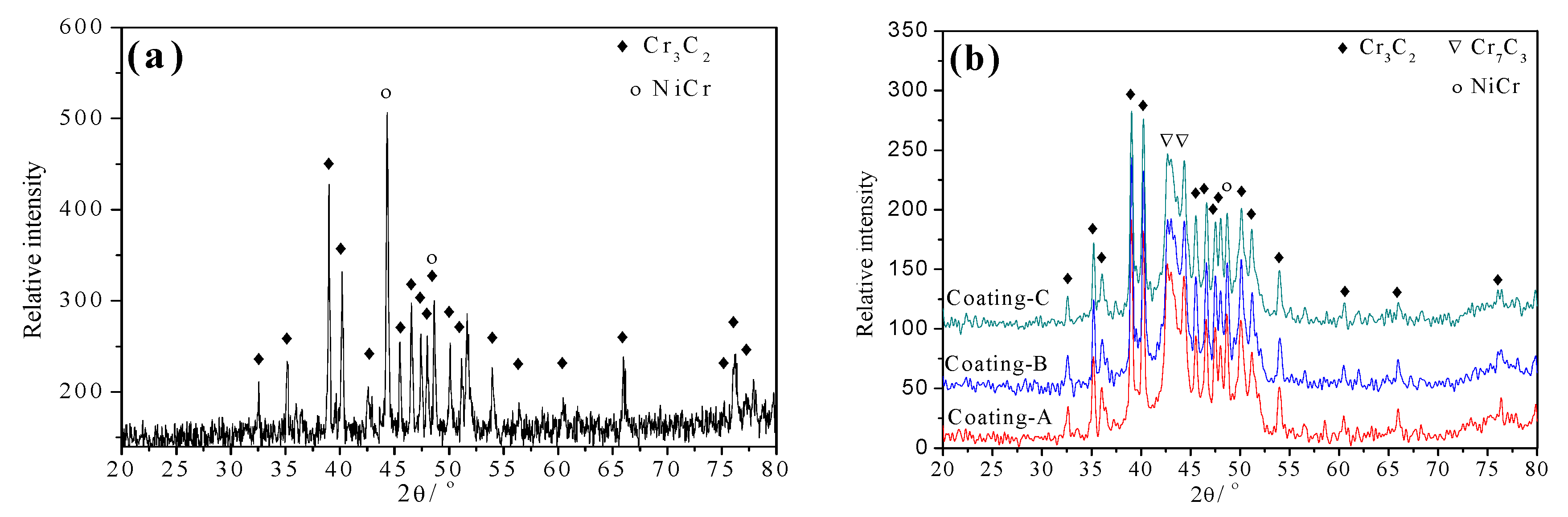
Figure 2.
SEM micrographs of the three coatings (a) coating-A, (b) coating-B, (c) coating-C.
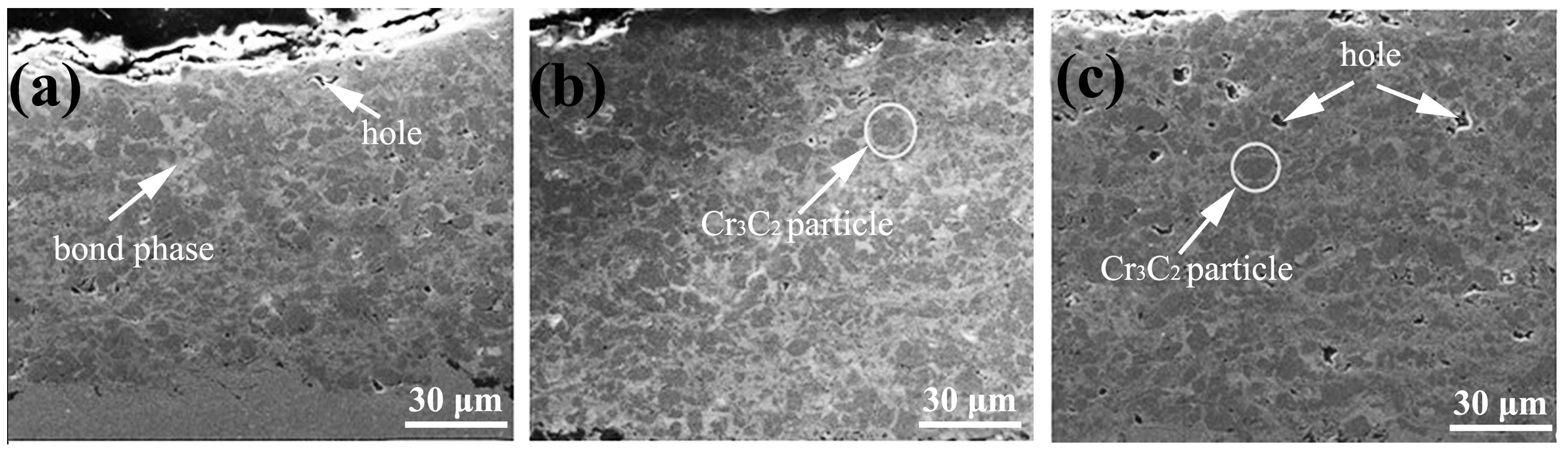
Figure 3.
Effect of powder feed rate on (a) porosity, (b) microhardness, (c) adhesion strength and (d) indention fracture toughness of Cr3C2-25NiCr coating.
Figure 3.
Effect of powder feed rate on (a) porosity, (b) microhardness, (c) adhesion strength and (d) indention fracture toughness of Cr3C2-25NiCr coating.
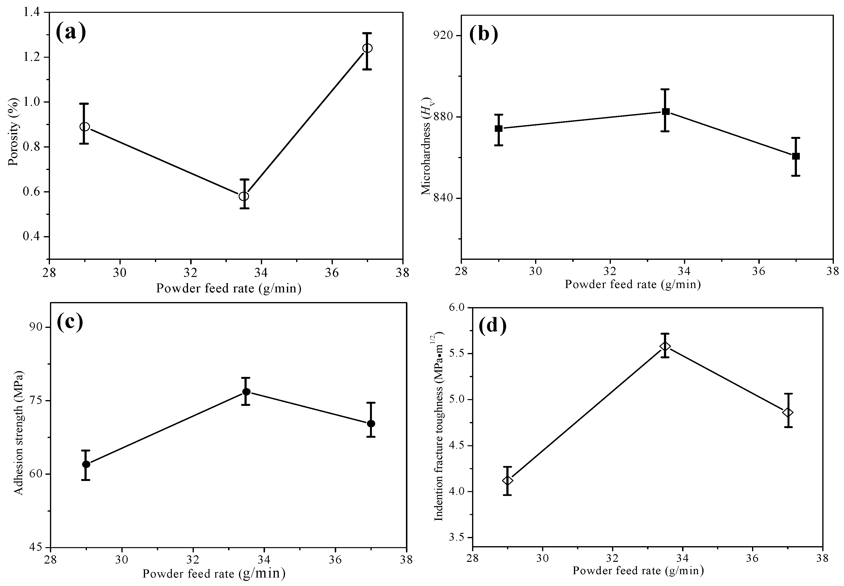
Figure 4.
Micrographs of Vickers indentations on transverse section of coatings (a) coating-A, (b) coating-B, (c) coating-C.
Figure 4.
Micrographs of Vickers indentations on transverse section of coatings (a) coating-A, (b) coating-B, (c) coating-C.
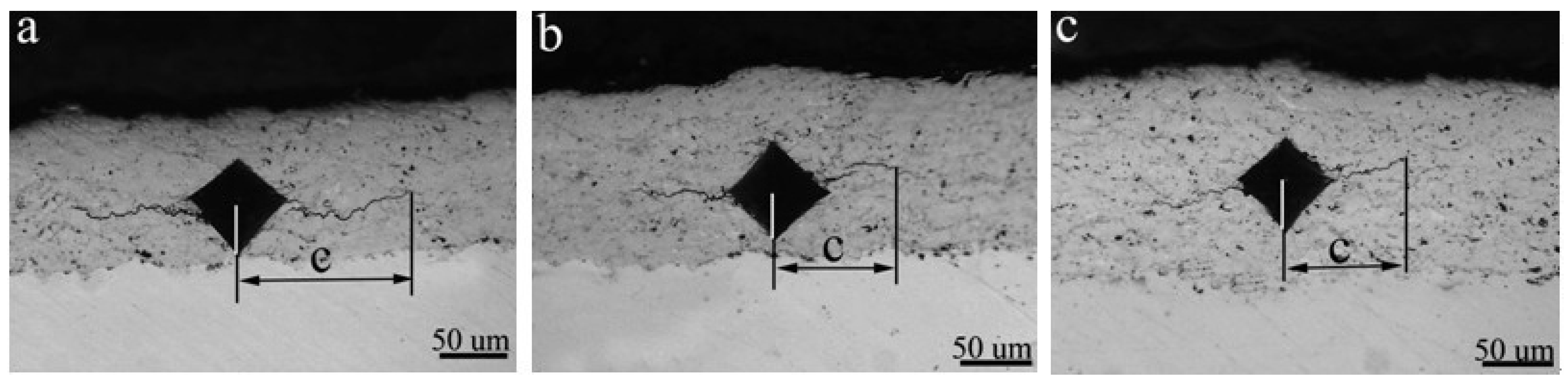
Figure 5.
The classification of nano-indentation readings on coatings (a) coating-A, (b) coating-B, (c) coating-C.
Figure 5.
The classification of nano-indentation readings on coatings (a) coating-A, (b) coating-B, (c) coating-C.

Figure 6.
SEM micrographs of the worn surfaces of coatings (a) coating-A, (b) coating-B, and (c) coating-C.
Figure 6.
SEM micrographs of the worn surfaces of coatings (a) coating-A, (b) coating-B, and (c) coating-C.
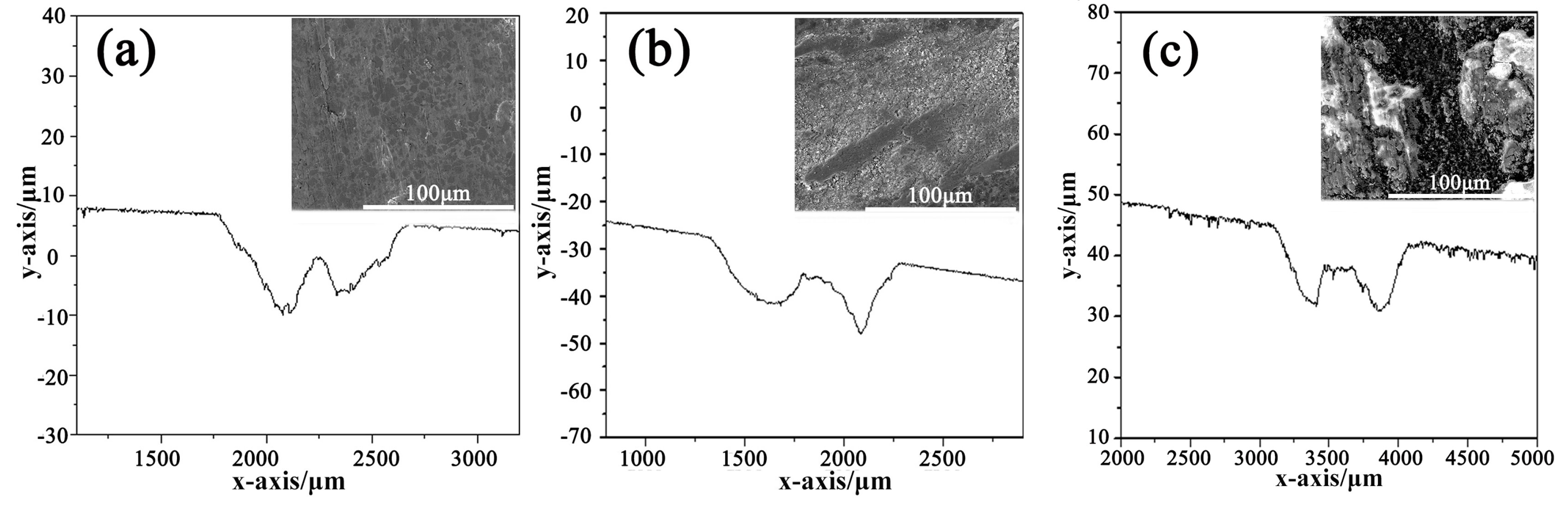
Figure 7.
SEM micrographs of the worn surfaces of coating-B.

Table 1.
Spray parameters of the three coatings.
| Coating | Combustion Pressure (bar) | Powder Feed Rate (g/min) | Fuel (L/h) | Oxygen (NLPM) | Spray Distance (mm) |
|---|---|---|---|---|---|
| A | 10.6 | 29 × 2 | 25.4 | 877 | 340 |
| B | 10.4 | 33.5 × 2 | 24.9 | 877 | 340 |
| C | 10.6 | 37 × 2 | 25.4 | 877 | 340 |
Table 2.
Characteristics of the three coatings.
| Coatings | Porosity (%) | Adhesion Strength (MPa) | Indention Fracture Toughness (MPa m1/2) | Hardness (HV) |
|---|---|---|---|---|
| A | 0.89 ± 0.09 | 62.0 ± 2.8 | 4.12 ± 0.2 | 874.2 ± 11.4 |
| B | 0.58 ± 0.14 | 73.8 ± 3.2 | 5.58 ± 0.3 | 882.6 ± 13.2 |
| C | 1.12 ± 0.20 | 61.3 ± 1.8 | 4.86 ± 0.7 | 860.6 ± 10.3 |
Table 3.
The wear rates of the coatings.
| Coating Type | Friction Coefficient | Wear rate (10−15 m3/N·m) |
|---|---|---|
| A | 0.33 ± 0.04 | 7.07 ± 0.84 |
| B | 0.30 ± 0.02 | 6.47 ± 0.68 |
| C | 0.37 ± 0.07 | 7.31 ± 1.27 |
© 2017 by the authors. Licensee MDPI, Basel, Switzerland. This article is an open access article distributed under the terms and conditions of the Creative Commons Attribution (CC BY) license (http://creativecommons.org/licenses/by/4.0/).
Share and Cite
MDPI and ACS Style
Xie, M.; Lin, Y.; Ke, P.; Wang, S.; Zhang, S.; Zhen, Z.; Ge, L. Influence of Process Parameters on High Velocity Oxy-Fuel Sprayed Cr3C2-25%NiCr Coatings. Coatings 2017, 7, 98. https://doi.org/10.3390/coatings7070098
AMA Style
Xie M, Lin Y, Ke P, Wang S, Zhang S, Zhen Z, Ge L. Influence of Process Parameters on High Velocity Oxy-Fuel Sprayed Cr3C2-25%NiCr Coatings. Coatings. 2017; 7(7):98. https://doi.org/10.3390/coatings7070098
Chicago/Turabian StyleXie, Mingxiang, Yue Lin, Peng Ke, Shuoyu Wang, Shihong Zhang, Zhicheng Zhen, and Liangshui Ge. 2017. "Influence of Process Parameters on High Velocity Oxy-Fuel Sprayed Cr3C2-25%NiCr Coatings" Coatings 7, no. 7: 98. https://doi.org/10.3390/coatings7070098
Note that from the first issue of 2016, this journal uses article numbers instead of page numbers. See further details here.