Phase and Microstructural Correlation of Spark Plasma Sintered HfB2-ZrB2 Based Ultra-High Temperature Ceramic Composites


High Temperature Ceramic Laboratory, Department of Materials Science and Engineering, Indian Institute of Technology Kanpur, Kanpur 208016, India
*
Author to whom correspondence should be addressed.
Coatings 2017, 7(8), 110; https://doi.org/10.3390/coatings7080110
Submission received: 31 May 2017
/
Revised: 7 July 2017
/
Accepted: 13 July 2017
/
Published: 26 July 2017
(This article belongs to the Special Issue Ultrahigh Temperature Ceramic Coatings and Composites)
Abstract
:The refractory diborides (HfB2 and ZrB2) are considered as promising ultra-high temperature ceramic (UHTCs) where low damage tolerance limits their application for the thermal protection system in re-entry vehicles. In this regard, SiC and CNT have been synergistically added as the sintering aids and toughening agents in the spark plasma sintered (SPS) HfB2-ZrB2 system. Herein, a novel equimolar composition of HfB2 and ZrB2 has shown to form a solid-solution which then allows compositional tailoring of mechanical properties (such as hardness, elastic modulus, and fracture toughness). The hardness of the processed composite is higher than the individual phase hardness up to 1.5 times, insinuating the synergy of SiC and CNT reinforcement in HfB2-ZrB2 composites. The enhanced fracture toughness of CNT reinforced composite (up to a 196% increment) surpassing that of the parent materials (ZrB2/HfB2-SiC) is attributed to the synergy of solid solution formation and enhanced densification (~99.5%). In addition, the reduction in the analytically quantified interfacial residual tensile stress with SiC and CNT reinforcements contribute to the enhancement in the fracture toughness of HfB2-ZrB2-SiC-CNT composites, mandatory for aerospace applications.
1. Introduction
Carbon-carbon (C–C) composites are attractive materials for hypersonic flight vehicles but they oxidize in air at temperatures >500 °C and needs thermal protection systems (TPS) to survive aero-thermal heating [1]. Ultra high-temperature ceramics (UHTCs) are ideal for the use in TPS for the next generation hypersonic vehicles operating above 2000 °C in both neutral and oxidizing environment [2]. The UHTC ceramic coatings provides the oxidation protection of C–C composites and should be: (1) well-adhered to provide erosion resistance; (2) resist the diffusion of oxygen through coating and thus, the substrate; (3) mechanically compatible to prevent coating spallation due to the mismatch in the thermal expansion during harsh aero-thermal conditions; and (4) reliability and reproducibility during processing [1,3]. Among UHTC family, zirconium diboride (ZrB2) and hafnium diboride (HfB2) owing to melting points above 3000 °C (3245 °C and 3380 °C, respectively), high electrical (1 × 10⁷ S/m and 9.1 × 10⁶ S/m, respectively) and thermal conductivity (60 W/mK and 104 W/mK, respectively), good chemical inertness and high wear resistance [4] emerge as leading candidate materials for the high-temperature structural applications in aerospace, refractory, and automotive sectors [5].
As a result of the strong covalent bonding and low self-diffusion coefficients of ZrB2 and HfB2, the obtainment of highly dense compacts has often required higher pressure (>20 MPa) and prolonged exposure of 2–3 h in atmosphere-controlled conventional furnaces at sintering temperatures >2000 °C [5,6]. In recent years, spark plasma sintering (SPS) has emerged as a potential technique for the processing of UHTCs with enhanced densification, fine grain size of a few microns at a much lower sintering temperature ~500 °C less than the conventional techniques and time 10–30 min [7,8,9,10,11]. Further, reinforcements such as SiC and TaSi2 not only act as a sintering aid to densify the ZrB2/HfB2 ceramics, but also enhances their mechanical, oxidation, and tribological performances [7,8,12,13,14,15]. Several investigations proved that the addition of SiC leads to the enhancement of the oxidation resistance of boride based UHTC [7]. Hot-pressed HfB2-20 vol % SiC and ZrB2-20 vol % SiC ceramics was flown on NASA-funded hypervelocity slender-body flight tests (nose tip radius of 3.5 mm) in 1997 during the SHARP-B1 program (NASA, Washington, WA, USA) and as components of leading-edge strakes in 2000 during the SHARP-B2 program (NASA, Washington, WA, USA), which successfully showed the non-ablating performance of borides ceramics [16]. Although the material HfB2/ZrB2-SiC is currently set as the baseline material based on their high-temperature thermo-mechanical performances [17], but there is still a need to further enhance their fracture strength and toughness. Thus, it is likely to further reinforce these material with nano-scale filler such as carbon nanotube (CNT), graphite and carbon fibers in order to improve its fracture toughness, lower its density, enhances densification and impart an acceptable level of thermal shock making UHTC a preferred candidate for aerospace applications [7,18,19,20,21]. A study [7] revealed that the addition of CNT in ZrB2-20SiC ceramic increases the fracture toughness up to ~53% (with 10 vol % of CNT addition) and enhances the oxidation resistance via grain sealing mechanism under 30 s plasma arc jet exposure with a flux of 2.5 MW/m2. It has also been proposed that incorporation of carbon removes the native oxides on the surfaces of the non-oxide ceramics by interfacial reactions and promotes densification [22].
A recent report on ZrB2-SiC with addition of HfB2 (0, 5, 10 and 15 vol %) has shown that flexural strength increases from ~284 MPa to ~356 MPa due to the formation of (Hf,Zr)B2 solid solution [23]. Herein, the idea of solid solution formation of (Hf,Zr)B2 is utilized on HfB2-ZrB2 system (in a 1:1 ratio) and the influence of SiC and CNT reinforcements on sintering of the HfB2-ZrB2 system has been investigated and compared with the established parent materials HfB2-20SiC (vol %) and ZrB2-20SiC (vol %) based UHTC [6,24,25]. To make reliable UHTC coating, it is important to thoroughly understand the physical and chemical properties of the coated materials. In this regard, the present study stems to the bulk material properties which is imperative to study for isolating the substrate effect (C–C, SiC–C composites, etc.). The sintered HfB2-ZrB2-SiC-CNT pellets were characterized in terms of microstructure, mechanical properties (hardness, elastic modulus, and fracture toughness), and the obtained results are correlated with the generation of effective residual stresses in the material during SPS processing.
2. Materials and Method
2.1. Processing of Composites
Commercial powders of HfB2 and ZrB2 (Samics Research Materials, Rajasthan, India, 99.7% pure, particle size <5 μm, irregular shape), SiC (H.C. Starck, Selb, Germany, 99.9% pure, particle size <1 μm, irregular shape) and multi-walled carbon nanotubes (CNT, Nanostructured and Amorphous Materials Inc., Houston, TX, USA, 95% pure, with an outer diameter of 40 nm, wall thickness of 20 nm, and 1–2 μm long) were used as the starting materials. SEM micrographs of the selected borides HfB2 (Figure 1a) and ZrB2 (Figure 1b), and the reinforcements SiC (Figure 1c) and CNT (Figure 1d) elicits the morphology and size of the starting powders. The following powder mixtures (1) HfB2-20 vol % SiC (labeled as H20S), (2) ZrB2-20 vol % SiC (labeled as Z20S), (3) HfB2-ZrB2 (in 1:1 ratio)-20 vol % SiC (labeled as HZ20S), and (4) HfB2-ZrB2 (in 1:1 ratio)-20 vol % SiC-6 vol % CNT (labeled as HZ20S6C) are used in the present study. The powder mixtures were dry ball milled with ball to powder weight ratio of 5:2 using tungsten carbide jar and tungsten carbide balls for 8 min at 500 rpm. The ball milling parameters were carefully chosen to avoid any structural damage to the CNT [7].
The milled composite powders were then processed via spark plasma sintering (SPS, Dr. Sinter 515S, Kanagawa, Japan) at 1850 °C under a vacuum (<6 Pa) with the uniaxial pressure of 30 MPa and hold time of 10 min at a heating rate of 100 °C/min during the sintering cycle. Graphite dies and punches were used for fabricating pellets of 15 mm diameter and 5 mm thickness. The ram displacement data during the SPS sintering cycle is utilized to investigate the densification behavior. The instantaneous densification of the composites is analyzed using the formula [26]:
where, hf, df, and di are the thickness of sintered sample, maximum displacement, and instantaneous displacement during sintering, respectively. The final density was measured via Archimedes method on a hydrostatic balance using ethanol as an immersion media.
2.2. Phase, Microstructural and Mechanical Characterization
X-ray diffraction (XRD) pattern of SPS processed HfB2-ZrB2-SiC-CNT composites was obtained using Cu Kα radiation (λ = 1.54 Å, PANalytical Empyrean diffractometer, Tokyo, Japan) operating at 25 kV and 15 mA with a scan speed of 0.5 s/step and at a step size of 0.02° in the 2θ range from 20° to 90°. Further, the structural damage to CNT during processing was evinced using Nd-YAG green laser micro-Raman spectroscopy (λ = 532 nm, Princeton Instruments, Tokyo, Japan, STR Raman, TE-PMT detector) in the backscattering mode with an exposure of 10 s.
The microstructure of the ground and polished surface (using 0.1 μm diamond suspension) of HfB2-ZrB2-SiC-CNT composites was observed using scanning electron microscope (SEM, Zeiss, Oberkochen, Germany, Model EVO 50). The energy dispersive X-ray analysis (EDX) at a point is used to confirm various phases in SPS processed HfB2-ZrB2-SiC-CNT composites. To see the structure of the CNTs, samples were fractured and observed using field emission SEM (FE-SEM, JEOL, JSM-7100F, Peabody, MA, USA).
Load displacement curves for polished sintered HfB2-ZrB2-SiC-CNT pellets were measured via instrumented micro Vickers indenter of type V-I 51 (MHT, CSM instruments, Peseux, Switzerland) at a loading rate of 4 N/min and holding of 10 s at maximum load of 2 N. Fracture toughness was calculated at a load (P of 49 N) using Vickers indenter via universal hardness testing machine (FH-10, Tinius-Olsen Ltd., Salfords, UK) with a dwell time of 10 s. The crack lengths (c) from the center of indents were measured using SEM and fracture toughness was computed using Anstis’ equation [27]:
where E is the elastic modulus and H is the hardness (measured experimentally) of HfB2-ZrB2-SiC-CNT composites. An average of ten values is reported for each composite. For evaluating the fracture toughness, indentation technique is not very suitable when compared with that of SENB method [28,29], but a similar trend of fracture toughness has been reported in literature [27,30]. With reference from the study [31], the indentation technique might not give the true fracture toughness values of the CNT reinforced composite, which may be attributed to minimal radial cracking in comparison to the observation of larger cracks in the composites without CNT reinforcement. The absence of cracking in the CNT reinforced composite via indentation is reasoned to their assisted shear deformation under the indenter [31]. For that matter it is important to be noted here that herein the indentation fracture toughness technique is used only as a “ranking parameter” towards comparing the toughness of processed HfB2-ZrB2-SiC-CNT composites.
The measurement of the critical energy release rate (GIC) is calculated using the following equation
where ν is the Poisson’s ratio calculated using rule of mixture for all composites [7].
3. Results and Discussion
3.1. Densification of HfB2-ZrB2-SiC-CNT Composites
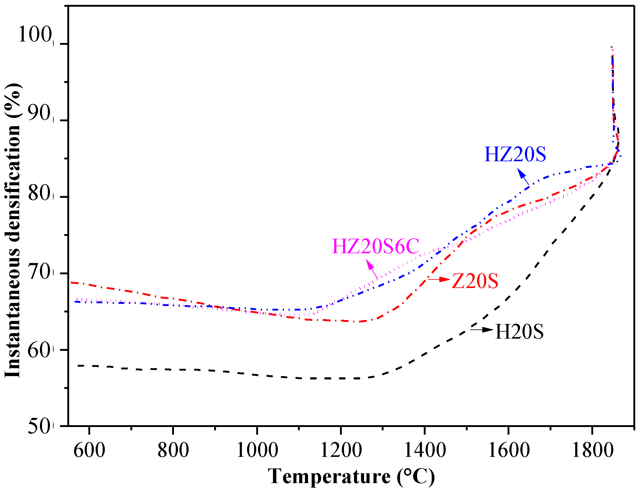
The instantaneous relative density as a function of sintering temperature during SPS processing of HfB2-ZrB2-SiC-CNT composites is presented in Figure 2. The addition of SiC in HfB2 and ZrB2 has led to nearly full densification (100% for H20S, ~99% for Z20S) is attributed to the high thermal conductivity of SiC and its ability to sit near the grain boundary which aids densification, allowing the sintering to be faster and at lower temperatures [7,12]. The densification was found to decrease in HZ20S (from ≤1% in H20S and Z20S to ~4% in HZ20S, see Table 1) is commensurate with recent report in literature [23] which shows that the addition of HfB2 in ZrB2 increases porosity due to the occurrence of chemical reaction between them. On the other hand, further addition of CNT (i.e., HZ20S6C), increases the densification to ~99.5% which is attributed to the high thermal conductivity of CNT [12,32]. Moreover, carbon has long been used as a sintering aid for the densification of a ceramics, and it is often proposed that incorporation of carbon removes the native oxides on the surfaces of the non-oxide ceramics by interfacial reactions and promotes the densification [15].
3.2. Phase Analysis of HfB2-ZrB2-SiC-CNT Composites
The XRD pattern of HfB2-ZrB2-SiC-CNT composites shown in Figure 3 indicates the retention of the starting phases even after SPS processing. Due to the poor X-ray reflecting ability, SiC peak intensity appears low [22] in the XRD pattern (Figure 3). In addition, no peak-shift in SiC phase is observed in all the processed SPS pellet when compared to that of starting powders, which confirms that SiC has not formed any solid solutions with HfB2/ZrB2 up to the processing temperature of 1850 °C. HZ20S and HZ20S6C composites show peak broadening and merging as shown in the marked region, Figure 3 indicating the formation of partial solid-solution as few peaks corresponding to the parent phases (HfB2/ZrB2) were also observed. Formation of HfB2-ZrB2 solid solution may be attributed to their nearly equal lattice parameters (a = 3.167 Å, c = 3.53 Å for ZrB2, and a = 3.165 Å and c = 3.51 Å for HfB2; calculated using Xpert high score plus software, 3.0.0.123, PANalytical, Tokyo, Japan) [33,34]. In literature, Post et al. [35] has also reported the complete mutual solubility in borides.
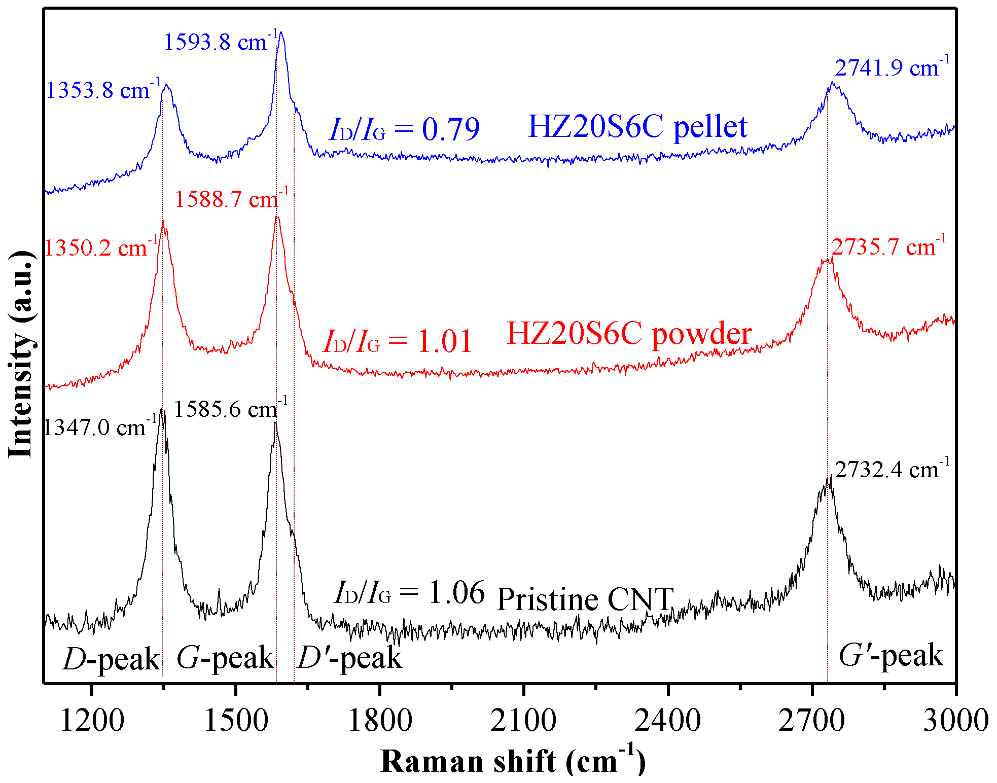
The D, G, and G’ peaks in the Raman spectra (see Figure 4) confirm the presence of CNTs in the ball milled and sintered HfB2-ZrB2-SiC-CNT pellets. Raman peaks for pristine CNT powders are observed at 1347.0 cm−1 (D-peak, arises from disorder and defects), 1585.6 cm−1 (G-peak, corresponds to C–C stretching mode from doubly degenerated phonon E2g at the Brillouin zone center) and at 2732.4 cm−1 (G’-peak, corresponds to the second-order phonon counter part of G) [36]. The peak shift of D (1350.2 cm−1 and 1353.8 cm−1), G (1588.7 cm−1 and 1593.8 cm−1) and G’ (2735.7 cm−1 and 2741.9 cm−1) peaks to higher wave numbers, respectively, in the ball milled and SPS pellets, indicate the generation of compressive stresses in the CNTs during ball milling [7,18] and after sintering. The development of compressive stress in the CNT is attributed to the thermal contraction of the ceramic matrix during cooling (discussed in the later Section 3.5). The defect to graphitic peak ratio, ID/IG remains similar for pristine CNT powder (=1.06) as well as ball milled powder (=1.01). However, ID/IG decreases to 0.79 for the SPS processed pellet, which elicits the conversion of CNTs to graphite-like structures [37]. Similar observation is also reported for TaC-CNT ceramic composite [32].
3.3. Microstructural Analysis of HfB2-ZrB2-SiC-CNT Composites
The surface morphology of the SPS processed HfB2-ZrB2-SiC-CNT composites, Figure 5 elucidates the uniform distribution of SiC and CNT phases (black color phase) in the matrix. Both samples, H20S (Figure 5a) and Z20S (Figure 5b) show a highly dense structure with no porosity which is in accordance with that measured using Archimedes method (see Table 1). However, despite having the same initial grain size (<5 μm), ZrB2 grains tend to grow bigger (~10–20 μm) when compared with HfB2 (~7–10 μm), which is attributed to the similar sintering temperature (~1850 °C) during SPS when diffusivity of the two (ZrB2: 0.21 cm2/s and HfB2: 0.16 cm2/s [6]) is different. Similar to the XRD analysis (Figure 3), the formation of HfB2-ZrB2 solid solution was evinced in HZ20S (Figure 5c) and HZ20S6C (Figure 5d) pellets. Along with the uniform distribution SiC sits at the intergranular regions of HfB2 and ZrB2 matrices (tightly encapsulated within the matrices, see inset of Figure 5a,b) which might assist in enhancing the densification by occupying the pore volume and thus, mechanical properties. As seen from the microstructure (Figure 5c,d), the (Hf,Zr)B2 solid solution originates either from HfB2 or ZrB2 grains. HfB2 grains appeared brighter while ZrB2 grains appeared darker than the solid solution which supports the mutual solubility of borides at high temperature. Similar observation was reported by Silvestroni et al. for HfB2 reinforced with ZrB2 composites [34]. The porosity observed in HZ20S (Figure 5c) decreases with CNT reinforcement (Figure 5d) from ~4% to ~0.5% (see Figure 5e) is due to the ability of CNT to fill the gap and occupy pores [38]. It can also be anticipated that HfB2 has a negative effect on the densification of ZrB2-SiC composites, which is similar to the results obtained by Balak et al. [23]. The structure of the CNT is evident from the image shown in Figure 5f, and similar to SiC, CNT also sits at the intergranular regions of the HfB2-ZrB2 system. Such observations supports enhancement in the mechanical properties of the material by mitigating the failure at higher load, studied in the following section. The EDX results confirms the presence of various phases in the HfB2-ZrB2-SiC-CNT composite (marked point in Figure 5e), revealing that the dark gray grains are ZrB2 (not shown here), light phases are of HfB2, SiC in Figure 5g, along with the formation of HfB2-ZrB2 solid solution (Figure 5h). The presence of carbon in the marked region in Figure 5f is also confirmed from the EDX shown in Figure 5i.
3.4. Mechanical Characterization of HfB2-ZrB2-SiC-CNT Composites
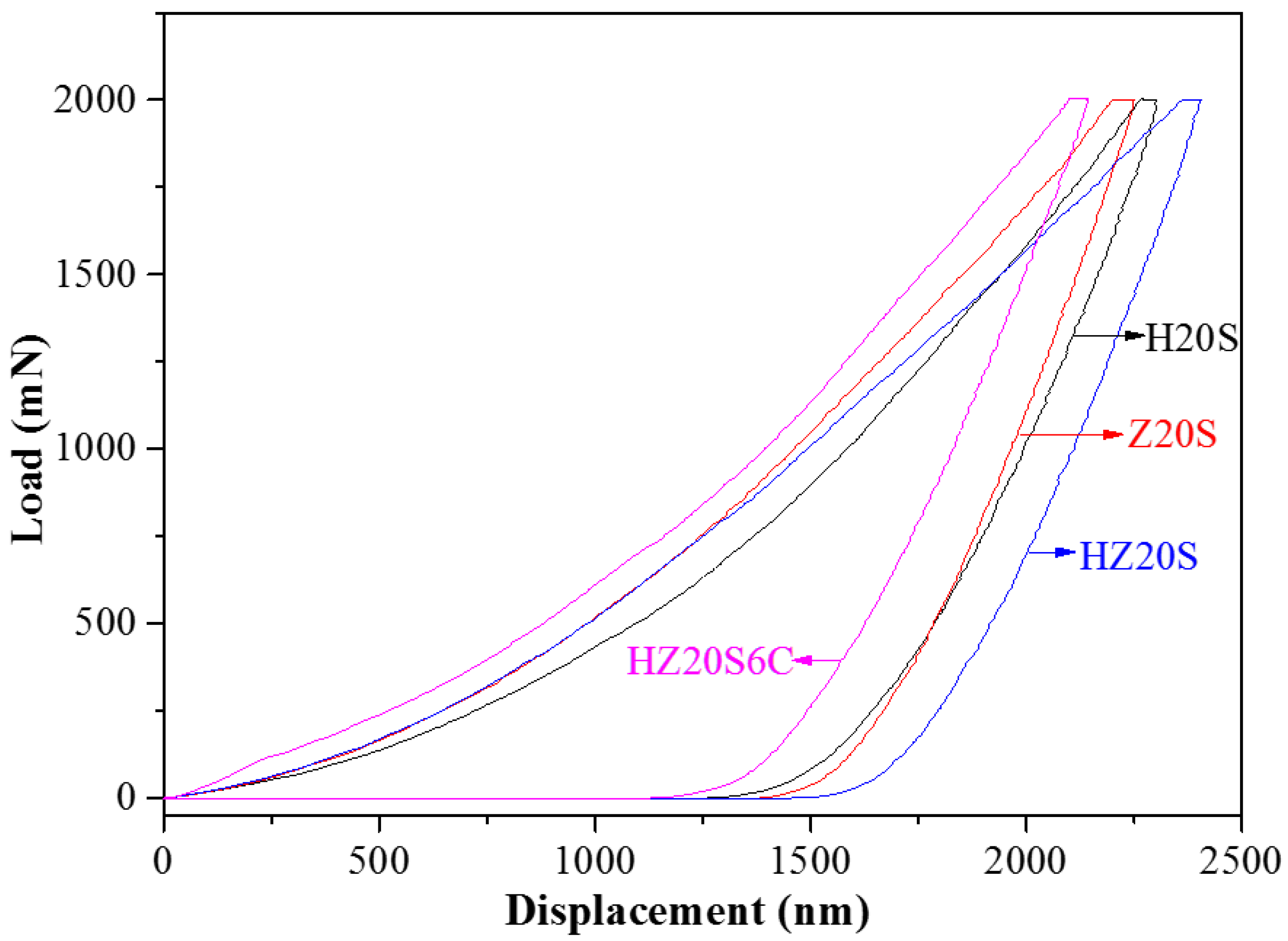
The structural integrity of the processed composite is evaluated using instrumented indentation technique. The load-displacement curves (see Figure 6) of HfB2-ZrB2-SiC-CNT composites were utilized to calculate hardness, Young’s modulus and plasticity index of HfB2-ZrB2-SiC-CNT composites, tabulated in Table 2. The hardness of the composites is found to be higher (up to 144% for HZ20S6C sample) than that calculated using rule of mixture (ROM), see Table 2. This is due to the limitation of ROM which doesn’t account for the microstructural features such as porosity, distribution of various phases, and interfaces governing the mechanical properties of a composite material. Such a behaviour establishes the synergy of reinforcement (SiC and CNT) and solid solution formation in HfB2-ZrB2 system. The hardness of the SPS processed H20S and Z20S is found to be 23.4 GPa and 23.6 GPa, respectively, is higher than the values reported for hot pressed samples (i.e., ~20.5 GPa for H20S and ~18.1 GPa for Z20S) [39]. This is attributed to the highly dense structure of HfB2 and ZrB2 with SiC reinforcement (porosity ≤ 1%) establishing the efficacy of the SPS technique in getting dense microstructure with superior mechanical properties of HfB2/ZrB2 based composites. In HZ20S samples, the formation of a solid solution should further increase the hardness, but, porosity has played a dominant role and has marginally decreased the hardness to 20.4 GPa. Further, synergistic interplay of CNT addition which acted both as a sintering aid (porosity decreases to ~0.5%) and toughening agent (shown later in this section); and (Hf,Zr)B2 solid solution led HZ20S6C sample to show highest hardness (~28.1 GPa) in the current system. Similar to hardness, the elastic modulus showed a minimum value for the HZ20S sample (425 GPa) and maximum for the HZ20S6C sample (528 GPa) revealing the combined effect of reinforcement (SiC and CNT), decreased porosity, and solid-solution.
Taking hardness of HfB2 = 18 GPa [40,41], ZrB2 = 15 GPa [5], SiC = 28 GPa [42], and CNT = 15 GPa (along radial direction) [43].
Based on the maximum depth (hm) and final depth (hf) of indentation, the plasticity index (re) i.e., the elastic recovery and the resistance to deformation (rd) for HfB2-ZrB2-SiC-CNT composites have been calculated using the following expression:
The increase in the elastic recovery (0.560–0.666, see Table 2) and decrease in the resistance to deformation (0.440–0.335, see Table 2) has resulted in the higher hardness and modulus of the HZ206C composite.
The fracture toughness of the SiC reinforced HfB2 and ZrB2 was observed to be 5.2 MPa·m0.5 and 5.7 MPa·m0.5, respectively, which is higher than the values reported in literature for SPS processed H20S (3.35 MPa·m0.5) and Z20S (3.91 MPa·m0.5) samples (the toughness was measured using indentation technique at a load of 49 N) [44]. The fracture toughness further increased to 8.7 MPa·m0.5 with SiC addition and 10.2 MPa·m0.5 with synergistic addition of SiC and CNT both in HfB2-ZrB2 system revealing the synergy of SiC and CNT as a toughening agent [7] and (Hf,Zr)B2 solid solution in enhancing the toughness. The critical energy release rate (GIC, see Table 2), which reckons the energy required to propagate a crack in the material, increases from 57.1 J·m−2 for H20S, to 63.0 J·m−2 for Z20S, to 176.8 J·m−2 for HZ20S and to 192.6 J·m−2 for HZ20S6C. Such a behavior can mitigate the failure at higher load by arresting the crack path making HZ20S6C a promising material where damage tolerance is an issue.
3.5. Effect of Residual Stress on the Mechanical Properties of HfB2-ZrB2-SiC-CNT Composites
The mechanism which governs the toughness of a composite material depends on: Tendency of crack bridging; micro-cracking due to misfit between coefficient of thermal expansion (CTE) which introduces stress field and residual stress due to difference in CTE of reinforcement (SiC and CNT); and matrix, which creates local compressive stress field in the matrix, thus, decreasing the stress intensity factor. Ignoring the effect of size and distribution of secondary phases (SiC and CNT), the generation of interfacial residual stresses in the material has been analytically computed. The linear CTE of a composite (assuming that each phase to be isotropic), computed by Levin, Rosen, and Hashin [45], is provided as:
where α, K, G and f are CTE, bulk modulus, shear modulus and volume fraction with subscript “m” and “r” set for matrix and reinforcement, respectively. Considering that KL ≤ Keff ≤ Ku, the upper (KL) and lower (Ku) bounds of bulk modulus can be obtained from Hashin-Shtrikman (HS) bounds [46]. Under such conditions, the above Equation (6) is modified to calculate both the upper (αeff)u and lower bounds (αeff)l of CTE in the following manner:
The values of ν (taken as 0.12, 0.11, 0.14 and 0.17, respectively for HfB2, ZrB2, SiC, and CNT), α (taken as 6.3 × 10⁻⁶ K−1, 5.9 × 10⁻⁶ K−1, 3.5 × 10⁻⁶ K−1, and 2.5 × 10⁻⁶ K−1, respectively for HfB2, ZrB2, SiC, and CNT), K (taken as 230 GPa, 229 GPa, 234 GPa, and 190 GPa, respectively for HfB2, ZrB2, SiC, and CNT) and G (taken as 212 GPa, 211 GPa, 41 GPa, and 150 GPa, respectively for HfB2, ZrB2, SiC, and CNT) used for calculations have been taken from the literature [4,6,7]. Since, the composites are being cooled from the final densification temperature (1850 °C) to room temperature; the matrix (HfB2, ZrB2, and equal proportions of both) tends to shrink faster than the reinforced particles (SiC and CNT) leading to compressive stress in the reinforced particles, σr and tensile stress state in the matrix, σm as evaluated using Taya’s model [47], tabulated in Table 3. The quantification of such thermal residual stresses is necessitated at high temperature during processing (taken as ΔT = 1400 °C [6]) where these stresses develop.
where, Er, Em, νr and νm are the Young’s modulus and Poisson’s ratio (calculated using ROM [7,17]) of the reinforcement and matrix respectively; is the thermal expansion misfit strain and ΔT is the temperature at which stresses begin to accumulate (set as 1400 °C) [48,49]. Young’s modulus for the reinforced phase, Er is estimated by ROM, utilizing modulus of matrix (HfB2/ZrB2/equal vol % of both) and composite (Ec) as presented in Table 2.
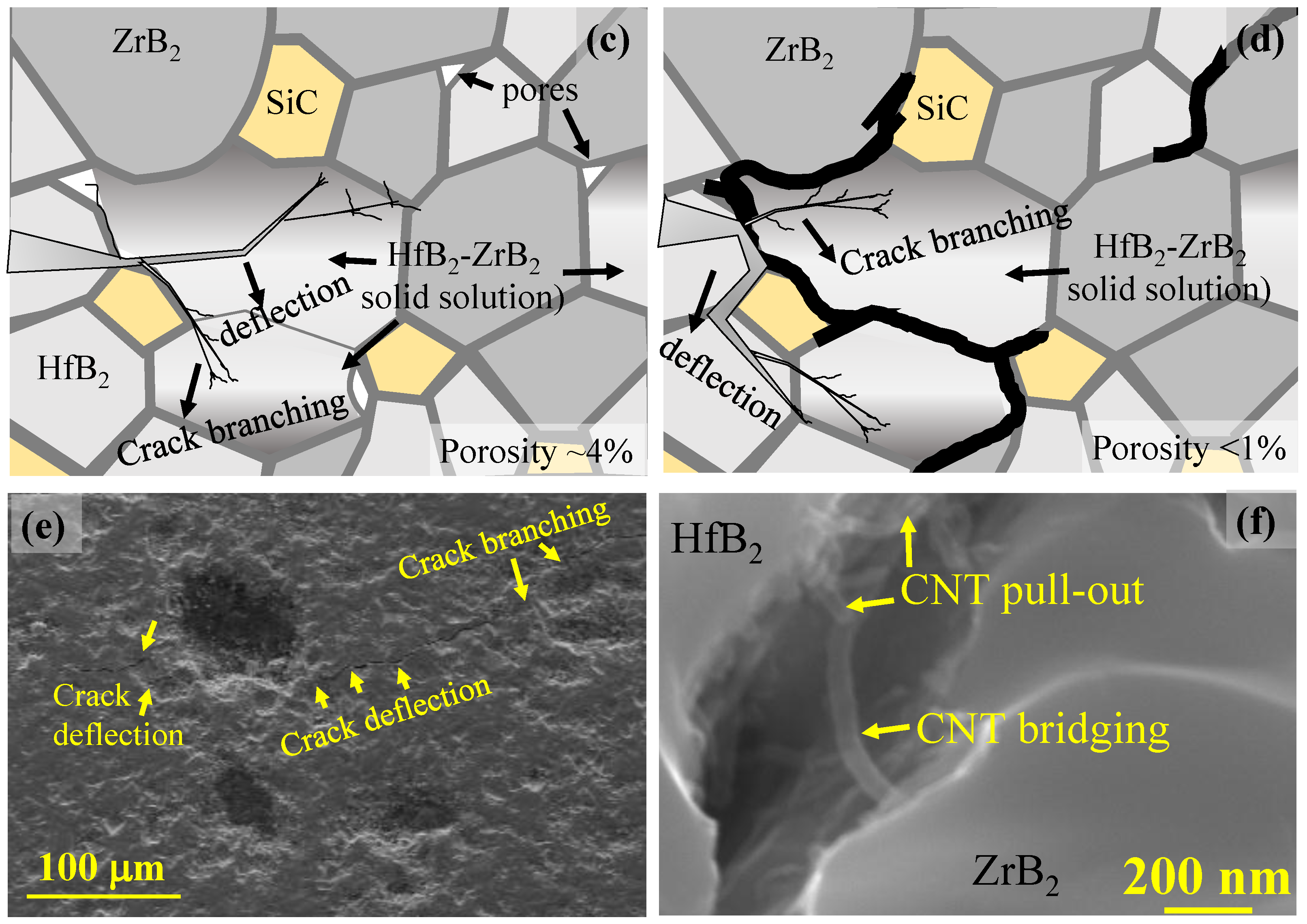
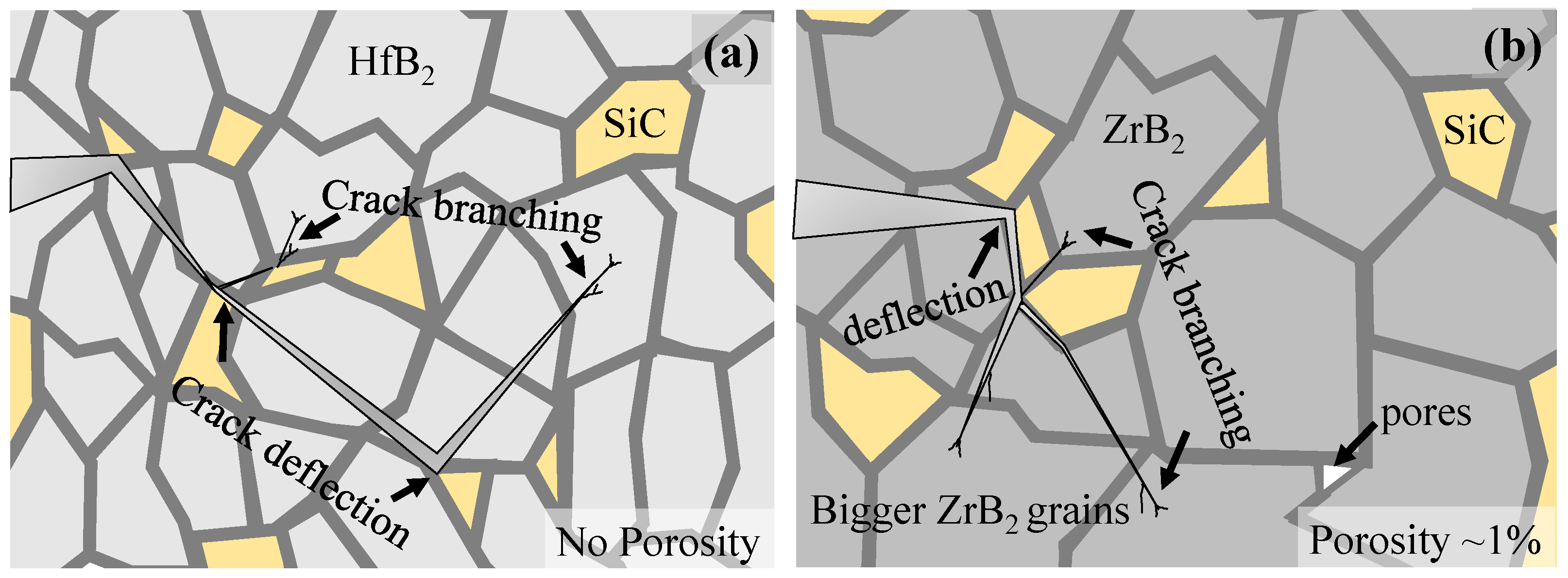
It is elucidated from Table 3 that the addition of secondary phase (SiC and CNT) introduce an interfacial stress (compressive in the reinforcement and tensile in the matrix), which provides enhanced structural integrity and toughness [12]. The increase in the interfacial compressive stress in the reinforcement (from 29.2 MPa and 32.8 MPa, respectively in the parent material H20S and Z20S, to 40.2 MPa in HZ20S, and to 42.8 MPa in HZ20S6C) lowers the high tensile stress in the matrix (from 669.1 MPa, and 806.3 MPa, respectively in H20S and Z20S, to 214.5 MPa in HZ20S and to 139.0 MPa in HZ20S6C) and thus, favors in enhancing the fracture toughness (from 5.2 MPa·m0.5 and 5.7 MPa·m0.5, respectively in the base material H20S and Z20S, to 8.7 MPa·m0.5 in HZ20S and to 10.2 MPa·m0.5 in HZ20S6C). The schematic illustration of the effect of SiC and CNT reinforcement on the microstructural evolution of HfB2, ZrB2, and HfB2-ZrB2 (1:1) system is elucidated in Figure 7. The propagation of the crack and its closure is restricted (for enhancement in the toughness) is attributed to the highly dense microstructure (≤1% porosity) and presence of SiC in H20S (Figure 7a) and Z20S (Figure 7b) which dissipate the energy via crack deflection mechanism, microstructurally shown in Figure 7e [7,12]. Analogous to solid solution strengthening mechanism in metal alloys, the solid solution formation of HfB2-ZrB2 (in HZ20S and HZ20S6C samples, see Figure 7c,d) create a local stress field which then mitigates the crack propagation along with the active bending and branching mechanism of SiC particle (Figure 7e), leading to an increase in the toughness when compared with H20S and Z20S (see Table 2). Further, the solid solution samples (HZ20S and HZ20S6C samples) show the presence of fine grains (Figure 5c–e) when compared with parent materials (H20S and Z20S samples, Z20S sample showed very large grains, see Figure 5a,b). The fine grains may serve as the energy-dissipation zone supporting the higher indentation toughness in solid solution samples [50]. Apart from this, the presence of CNT in the HZ20S6C sample enhances the fracture toughness via well-established CNT pull-out, deflection and branching mechanisms (shown in Figure 7f). Hence, it can be anticipated that the synergy of reinforcements (SiC and CNT) which act as a sintering aid and toughening along with the solid solution strengthening of (Hf,Zr)B2 alleviate the crack propagation making HZ20S6C sample a viable structural material for aerospace application.
4. Conclusions
Novel HfB2-ZrB2-SiC-CNT composites were densified to >96% of relative density using SPS at 1850 °C. The results showed that HfB2 and ZrB2 diffuses mutually to form (Zr,Hf)B2 solid solution, which enhances the fracture toughness of the material (HZ20S: 8.7 MPa·m0.5) when compared with H20S (5.2 MPa·m0.5) and Z20S (5.7 MPa·m0.5). The reinforcement of CNT (as HZ20S6C) and has led towards achieving the toughest ceramic (10.2 MPa·m0.5) in HfB2-ZrB2 system. The hardness of the processed composites is higher than the individual phase hardness (assessed using ROM), which establishes the synergy of SiC and CNT in enhancing the mechanical performance of HfB2-ZrB2 composites (HZ20S6C), attributed to the (Zr,Hf)B2 solid solution strengthening and enhanced densification with CNT reinforcement. The study reveals that the reinforcement generate interfacial residual stresses during processing which, then governs the strength of HfB2-ZrB2-SiC-CNT composites, making it mandatory for re-entry space structures where damage tolerance is an issue.
Acknowledgements
Authors at Indian Institute of Technology Kanpur (IITK) acknowledge the financial support received from IMpacting Research INnovation and Technology (IMPRINT) grant from the Department of Space, and Ministry of Human Resource Development (MHRD), Government of India. Authors acknowledge technical assistance from Advanced Centre of Materials Science (ACMS) at IIT Kanpur (for SEM and instrumented indentation facility).
Author Contributions
Ambreen Nisar designed and performed the experiments, analyzed the data and wrote the paper. Kantesh Balani conceived the idea, helped designing the experiment and guided in organizing and editing the paper.
Conflicts of Interest
The authors declare no conflict of interest.
References
- Corral, E.L.; Loehman, R.E. Ultra-high-temperature ceramic coatings for oxidation protection of carbon–carbon composites. J. Am. Ceram. Soc. 2008, 91, 1495–1502. [Google Scholar] [CrossRef]
- Balani, K.; Gonzalez, G.; Agarwal, A.; Hickman, R.; O’Dell, J.S.; Seal, S. Synthesis, microstructural characterization, and mechanical property evaluation of vacuum plasma sprayed tantalum carbide. J. Am. Ceram. Soc. 2006, 89, 1419–1425. [Google Scholar] [CrossRef]
- Levine, S.R.; Opila, E.J.; Halbig, M.C.; Kiser, J.D.; Singh, M.; Salem, J.A. Evaluation of ultra-high temperature ceramics foraeropropulsion use. J. Eur. Ceram. Soc. 2002, 22, 2757–2767. [Google Scholar] [CrossRef]
- Zapata-Solvas, E.; Jayaseelan, D.D.; Lin, H.T.; Brown, P.; Lee, W.E. Mechanical properties of ZrB2- and HfB2-based ultra-high temperature ceramics fabricated by spark plasma sintering. J. Eur. Ceram. Soc. 2013, 33, 1373–1386. [Google Scholar] [CrossRef]
- Fahrenholtz, W.G.; Hilmas, G.E.; Talmy, I.G.; Zaykoski, J.A. Refractory diborides of zirconium and hafnium. J. Am. Ceram. Soc. 2007, 90, 1347–1364. [Google Scholar] [CrossRef]
- Mallik, M.; Kailath, A.J.; Ray, K.; Mitra, R. Electrical and thermophysical properties of ZrB2 and HfB2 based composites. J. Eur. Ceram. Soc. 2012, 32, 2545–2555. [Google Scholar] [CrossRef]
- Nisar, A.; Ariharan, S.; Venkateswaran, T.; Sreenivas, N.; Balani, K. Effect of carbon nanotube on processing, microstructural, mechanical and ablation behavior of ZrB2–20SiC based ultra-high temperature ceramic composites. Carbon 2017, 111, 269–282. [Google Scholar] [CrossRef]
- Nisar, A.; Ariharan, S.; Venkateswaran, T.; Sreenivas, N.; Balani, K. Oxidation studies on tac based ultra-high temperature ceramic composites under plasma arc jet exposure. Corros. Sci. 2016, 109, 50–61. [Google Scholar] [CrossRef]
- Gild, J.; Zhang, Y.; Harrington, T.; Jiang, S.; Hu, T.; Quinn, M.C.; Mellor, W.M.; Zhou, N.; Vecchio, K.; Luo, J. High-entropy metal diborides: A new class of high-entropy materials and a new type of ultrahigh temperature ceramics. Sci. Rep. 2016, 6, 37946. [Google Scholar] [CrossRef] [PubMed]
- Anselmi-Tamburini, U.; Kodera, Y.; Gasch, M.; Unuvar, C.; Munir, Z.A.; Ohyanagi, M.; Johnson, S. Synthesis and characterization of dense ultra-high temperature thermal protection materials produced by field activation through spark plasma sintering (SPS): I. Hafnium diboride. J. Mater. Sci. 2006, 41, 3097–3104. [Google Scholar] [CrossRef]
- Wang, H.; Wang, C.-A.; Yao, X.; Fang, D. Processing and mechanical properties of zirconium diboride-based ceramics prepared by spark plasma sintering. J. Am. Ceram. Soc. 2007, 90, 1992–1997. [Google Scholar] [CrossRef]
- Nisar, A.; Ariharan, S.; Balani, K. Synergistic reinforcement of carbon nanotubes and silicon carbide for toughening tantalum carbide based ultrahigh temperature ceramic. J. Mater. Res. 2016, 31, 682–692. [Google Scholar] [CrossRef]
- Nisar, A.; Balani, K. Role of interfaces on multi-length scale wear mechanics of tac-based composites. Adv. Eng. Mater. 2017, 19. [Google Scholar] [CrossRef]
- Sciti, D.; Silvestroni, L.; Celotti, G.; Melandri, C.; Guicciardi, S. Sintering and mechanical properties of ZrB2–TaSi2 and HfB2–TaSi2 ceramic composites. J. Am. Ceram. Soc. 2008, 91, 3285–3291. [Google Scholar] [CrossRef]
- Musa, C.; Orrù, R.; Sciti, D.; Silvestroni, L.; Cao, G. Synthesis, consolidation and characterization of monolithic and SiC whiskers reinforced HfB2 ceramics. J. Eur. Ceram. Soc. 2013, 33, 603–614. [Google Scholar] [CrossRef]
- Bull, J.; Kolodziej, P.; Salute, J.; Keese, D. Design, Instrumentation and Preflight Testing of a Sharp Ultra-High Temperature Ceramic Nosetip; NASA TM-1998-112229; NASA: Washington, DC, USA, October 1998.
- Fahrenholtz, W.G.; Wuchina, E.J.; Lee, W.E.; Zhou, Y. Ultra-High Temperature Ceramics: Materials for Extreme Environment Applications; John Wiley & Sons: Hoboken, NJ, USA, 2014. [Google Scholar]
- Yadhukulakrishnan, G.B.; Rahman, A.; Karumuri, S.; Stackpoole, M.M.; Kalkan, A.K.; Singh, R.P.; Harimkar, S.P. Spark plasma sintering of silicon carbide and multi-walled carbon nanotube reinforced zirconium diboride ceramic composite. Mater. Sci. Eng. A 2012, 552, 125–133. [Google Scholar] [CrossRef]
- Tian, W.-B.; Kan, Y.-M.; Zhang, G.-J.; Wang, P.-L. Effect of carbon nanotubes on the properties of ZrB2–SiC ceramics. Mater. Sci. Eng. A 2008, 487, 568–573. [Google Scholar] [CrossRef]
- Wang, Z.; Hong, C.; Zhang, X.; Sun, X.; Han, J. Microstructure and thermal shock behavior of ZrB2–SiC–graphite composite. Mater. Chem. Phys. 2009, 113, 338–341. [Google Scholar] [CrossRef]
- Balani, K.; Bakshi, S.R.; Mungole, T.; Agarwal, A. Ab-initio molecular modeling of interfaces in tantalum-carbon system. J. Appl. Phys. 2012, 111, 063521–063527. [Google Scholar] [CrossRef]
- Liu, L.; Ye, F.; Zhang, Z.; Zhou, Y. Microstructure and mechanical properties of the spark plasma sintered TaC/SiC composites. Mater. Sci. Eng. A 2011, 529, 479–484. [Google Scholar] [CrossRef]
- Balak, Z.; Zakeri, M. Effect of HfB2 on microstructure and mechanical properties of ZrB2–SiC-based composites. Int. J. Refract. Metals Hard Mater. 2016, 54, 127–137. [Google Scholar] [CrossRef]
- Hu, P.; Guolin, W.; Wang, Z. Oxidation mechanism and resistance of ZrB2–SiC composites. Corros. Sci. 2009, 51, 2724–2732. [Google Scholar] [CrossRef]
- Squire, T.H.; Marschall, J. Material property requirements for analysis and design of UHTC components in hypersonic applications. J. Eur. Ceram. Soc. 2010, 30, 2239–2251. [Google Scholar] [CrossRef]
- Kumar, A.; Biswas, K.; Basu, B. On the toughness enhancement in hydroxyapatite-based composites. Acta Mater. 2013, 61, 5198–5215. [Google Scholar] [CrossRef]
- Anstis, G.R.; Chantiklul, P.; Lawn, B.R.; Marshall, D.B. A critical evaluation of indentation techniques for measuring fracture toughness: I, dircet crack measurements. J. Am. Ceram. Soc. 1981, 64, 533–538. [Google Scholar] [CrossRef]
- Awaji, H.; Sakaida, Y. V-notch technique for single-edge notched beam and chevron notch methods. J. Am. Ceram. Soc. 1990, 73, 3522–3523. [Google Scholar] [CrossRef]
- Wang, X.; Padture, N.P.; Tanaka, H. Contact-damage-resistant ceramic/single-wall carbon nanotubes and ceramic/graphite composites. Nat. Mater. 2004, 3, 539–544. [Google Scholar] [CrossRef] [PubMed]
- Chantikul, P.; Anstis, G.R.; Lawn, B.R.; Marshall, D.B. A critical evaluation of indentation techniques for measuring fracture toughness: II, strength method. J. Am. Ceram. Soc. 1981, 64, 539–543. [Google Scholar] [CrossRef]
- Sheldon, B.W.; Curtin, W.A. Nanoceramic composites: Tough to test. Nat. Mater. 2004, 3, 505–506. [Google Scholar] [CrossRef] [PubMed]
- Bakshi, S.R.; Musaramthota, V.; Virzi, D.A.; Keshri, A.K.; Lahiri, D.; Singh, V.; Seal, S.; Agarwal, A. Spark plasma sintered tantalum carbide–carbon nanotube composite: Effect of pressure, carbon nanotube length and dispersion technique on microstructure and mechanical properties. Mater. Sci. Eng. A 2011, 528, 2538–2547. [Google Scholar] [CrossRef]
- Rudy, E. Ternary Phase Equilibria in Transition Metal-Boron-Carbon-Silicon Systems. Part 5. Compendium of Phase Diagram Data; AD0689843; DTIC: Washington, WA, USA, 30 April 1969. [Google Scholar]
- Silvestroni, L.; Sciti, D.; Bellosi, A. Microstructure and properties of pressureless sintered HfB2-based composites with additions of ZrB2 or HfC. Adv. Eng. Mater. 2007, 9, 915–920. [Google Scholar] [CrossRef]
- Post, B.; Glaser, F.W.; Moskowitz, D. Transition metal diborides. Acta Metall. 1954, 2, 20–25. [Google Scholar] [CrossRef]
- Bakshi, S.R.; Musaramthota, V.; Lahiri, D.; Singh, V.; Seal, S.; Agarwal, A. Spark plasma sintered tantalum carbide: Effect of pressure and nano-boron carbide addition on microstructure and mechanical properties. Mater. Sci. Eng. A 2011, 528, 1287–1295. [Google Scholar] [CrossRef]
- Dresselhaus, M.S.; Jorio, A.; Hofmann, M.; Dresselhaus, G.; Saito, R. Perspectives on carbon nanotubes and graphene Raman Spectroscopy. Nano Lett. 2010, 10, 751–758. [Google Scholar] [CrossRef] [PubMed]
- Sonber, J.K.; Murthy, T.S.R.C.; Subramanian, C.; Krishnamurthy, N.; Hubli, R.C.; Suri, A.K. Effect of CrSi2 and HfB2 addition on densification and properties of ZrB2. Int. J. Refract. Metals Hard Mater. 2012, 31, 125–131. [Google Scholar] [CrossRef]
- Marschall, J.; Erlich, D.C.; Manning, H.; Duppler, W.; Ellerby, D.; Gasch, M. Microhardness and high-velocity impact resistance of HfB2/SiC and ZrB2/SiC composites. J. Mater. Sci. 2004, 39, 5959–5968. [Google Scholar] [CrossRef]
- Gasch, M.; Ellerby, D.; Irby, E.; Beckman, S.; Gusman, M.; Johnson, S. Processing, properties and arc jet oxidation of hafnium diboride/silicon carbide ultra high temperature ceramics. J. Mater. Sci. 2004, 39, 5925–5937. [Google Scholar] [CrossRef]
- Licheri, R.; Orrù, R.; Musa, C.; Locci, A.M.; Cao, G. Consolidation via spark plasma sintering of HfB2/SiC and HfB2/HfC/SiC composite powders obtained by self-propagating high-temperature synthesis. J. Alloys Compd. 2009, 478, 572–578. [Google Scholar] [CrossRef]
- Asl, M.S.; Kakroudi, M.G.; Noori, S. Hardness and toughness of hot pressed ZrB2–SiC composites consolidated under relatively low pressure. J. Alloys Compd. 2015, 619, 481–487. [Google Scholar] [CrossRef]
- Zhu, C.; Guo, W.; Yu, T.X.; Woo, C.H. Radial compression of carbon nanotubes: Deformation and damage, super-elasticity and super-hardness. Nanotechnology 2005, 16, 1035. [Google Scholar] [CrossRef]
- Hu, C.; Sakka, Y.; Byungkoog, J.; Tanaka, H.; Nishimura, T.; Shuqi, G.; Grasso, S. Microstructure and properties of ZrB2–SiC and HfB2–SiC composites fabricated by spark plasma sintering (SPS) using TaSi2 as sintering aid. J. Ceram. Soc. Jpn. 2010, 118, 997–1001. [Google Scholar] [CrossRef]
- Rosen, B.W.; Hashin, Z. Effective thermal expansion coefficients and specific heats of composite materials. Int. J. Eng. Sci. 1970, 8, 157–173. [Google Scholar] [CrossRef]
- Brown, H.L.; Armstrong, P.E.; Kempter, C.P. Elastic properties of some polycrystalline transition-metal monocarbides. J. Chem. Phys. 1966, 45, 547–549. [Google Scholar] [CrossRef]
- Taya, M.; Hayashi, S.; Kobayashi, A.S.; Yoon, H.S. Toughening of a particulate-reinforced ceramic-matrix composite by thermal residual stress. J. Am. Ceram. Soc. 1990, 73, 1382–1391. [Google Scholar] [CrossRef]
- Ghosh, D.; Subhash, G.; Orlovskaya, N. Measurement of scratch-induced residual stress within sic grains in ZrB2–SiC composite using micro-Raman Spectroscopy. Acta Mater. 2008, 56, 5345–5354. [Google Scholar] [CrossRef]
- Watts, J.; Hilmas, G.; Fahrenholtz, W.G.; Brown, D.; Clausen, B. Measurement of thermal residual stresses in ZrB2–SiC composites. J. Eur. Ceram. Soc. 2011, 31, 1811–1820. [Google Scholar] [CrossRef]
- Zhang, C.; Gupta, A.; Seal, S.; Boesl, B.; Agarwal, A. Solid solution synthesis of tantalum carbide-hafnium carbide by spark plasma sintering. J. Am. Ceram. Soc. 2017, 100, 1853–1862. [Google Scholar] [CrossRef]
Figure 1.
SEM micrographs of the starting powder (a) HfB2, and (b) ZrB2. TEM micrographs of the reinforcements: (c) SiC and (d) CNT.
Figure 1.
SEM micrographs of the starting powder (a) HfB2, and (b) ZrB2. TEM micrographs of the reinforcements: (c) SiC and (d) CNT.
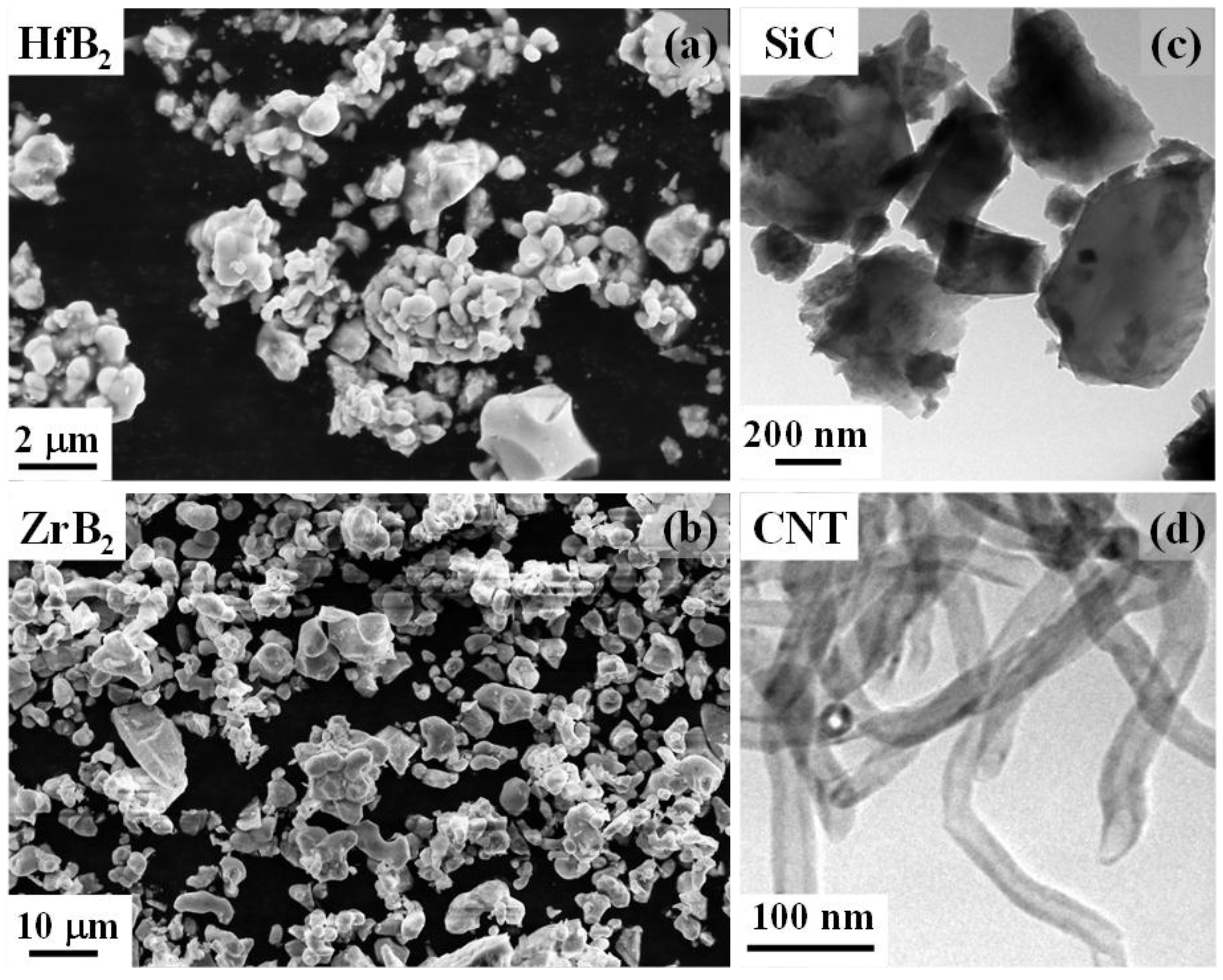
Figure 2.
Instantaneous relative density plot of HfB2-ZrB2-SiC-CNT composites.

Figure 3.
XRD spectra of initial composite powders as well as SPS processed HfB2-ZrB2-SiC-CNT composites.
Figure 3.
XRD spectra of initial composite powders as well as SPS processed HfB2-ZrB2-SiC-CNT composites.
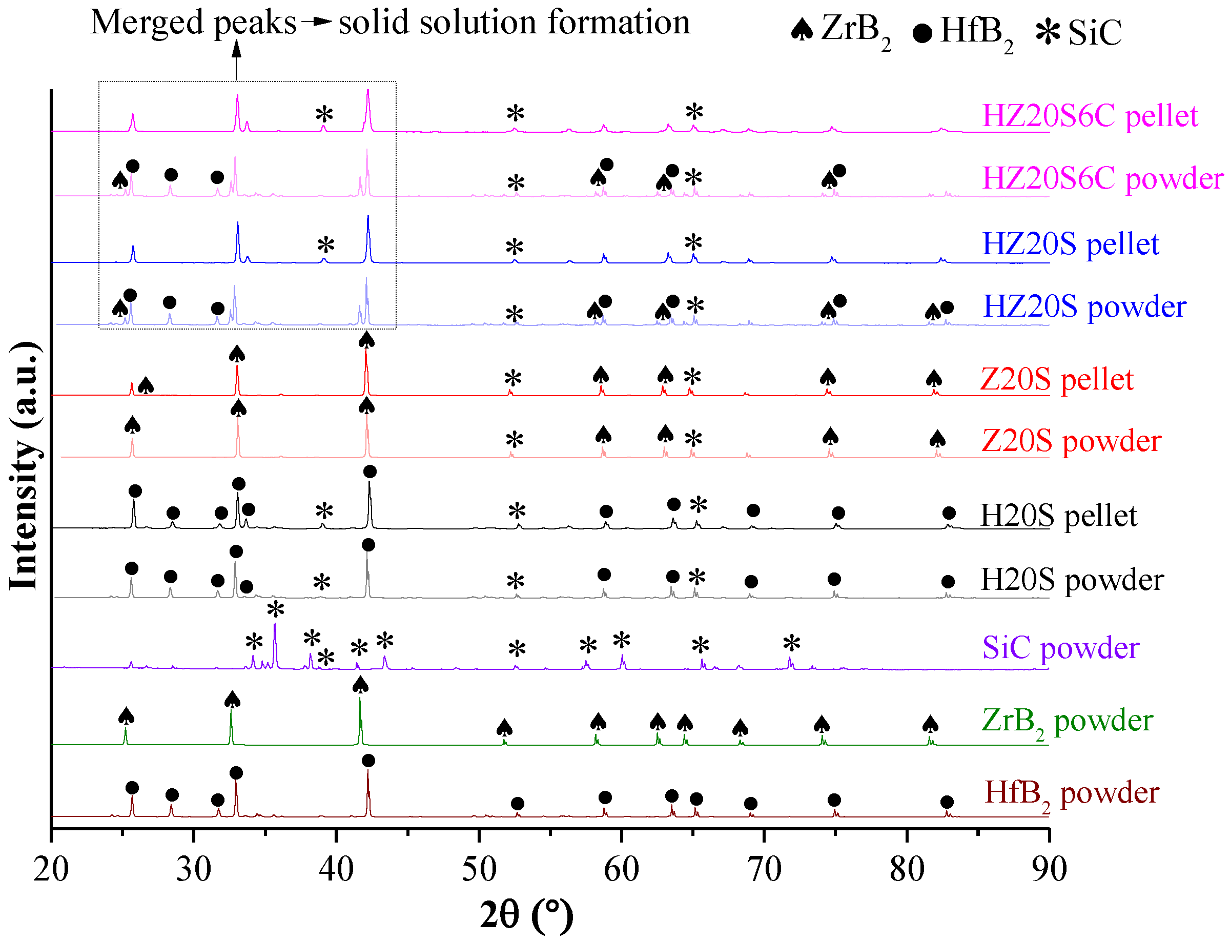
Figure 4.
Raman spectra showing D, G, D’, and G’ peak of CNT in CNT reinforced composite powder as well as a pellet.
Figure 4.
Raman spectra showing D, G, D’, and G’ peak of CNT in CNT reinforced composite powder as well as a pellet.

Figure 5.
Back scattered SEM images of the SPS processed HfB2-ZrB2-SiC-CNT composites: (a) H20S and inset shows that SiC sits at the intragranular regions, (b) Z20S, (c) HZ20S, (d) HZ20S6C, high magnification image (e) eliciting mutual diffusion of HfB2 and ZrB2 of the marked area in (c) and (f) marked area in (d) showing the presence and morphology of the CNT remains intact even after SPS processing. EDS of the marked region confirming presence of (g) SiC, (h) solid solution of HfB2 and ZrB2; and (i) CNT.
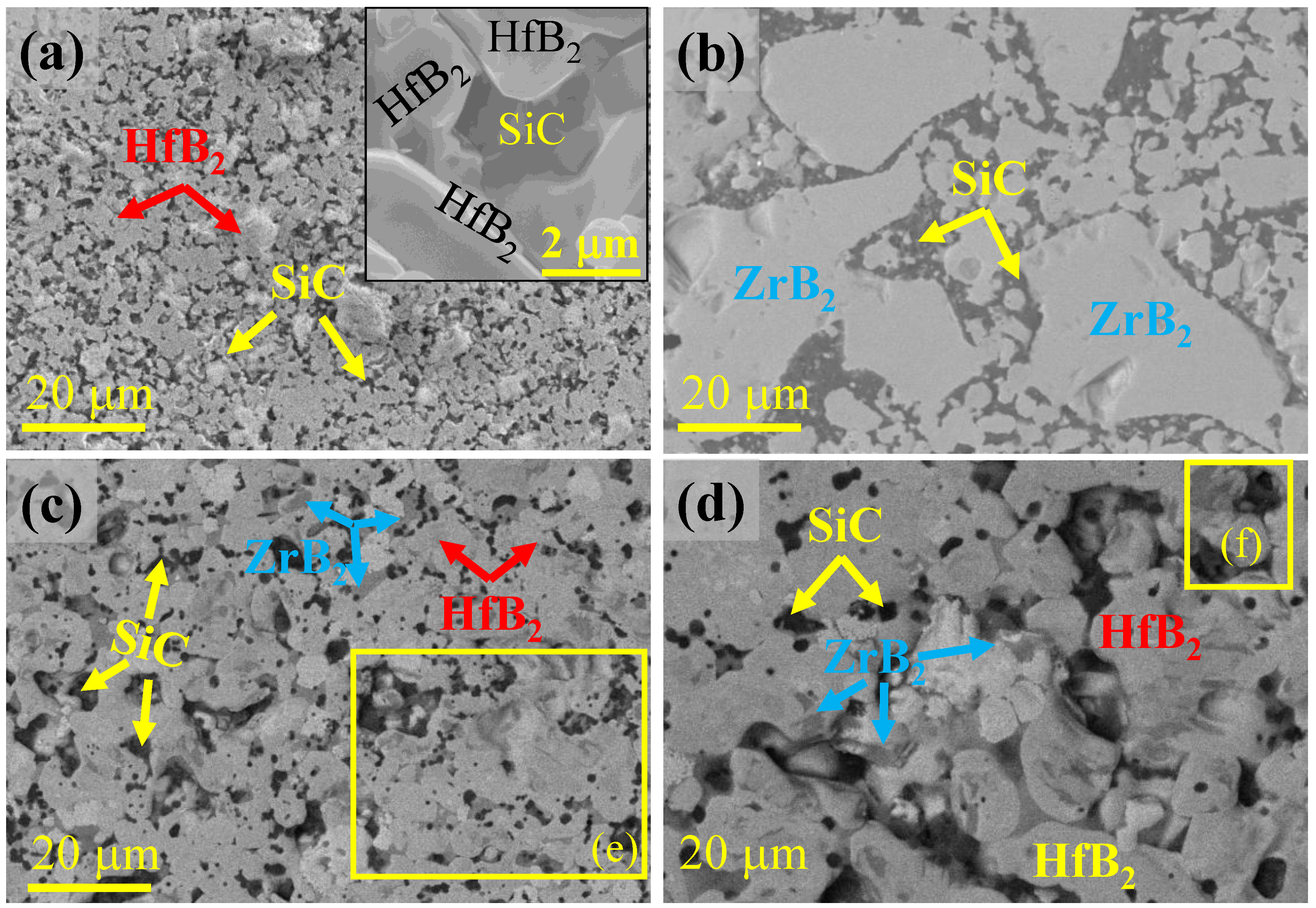
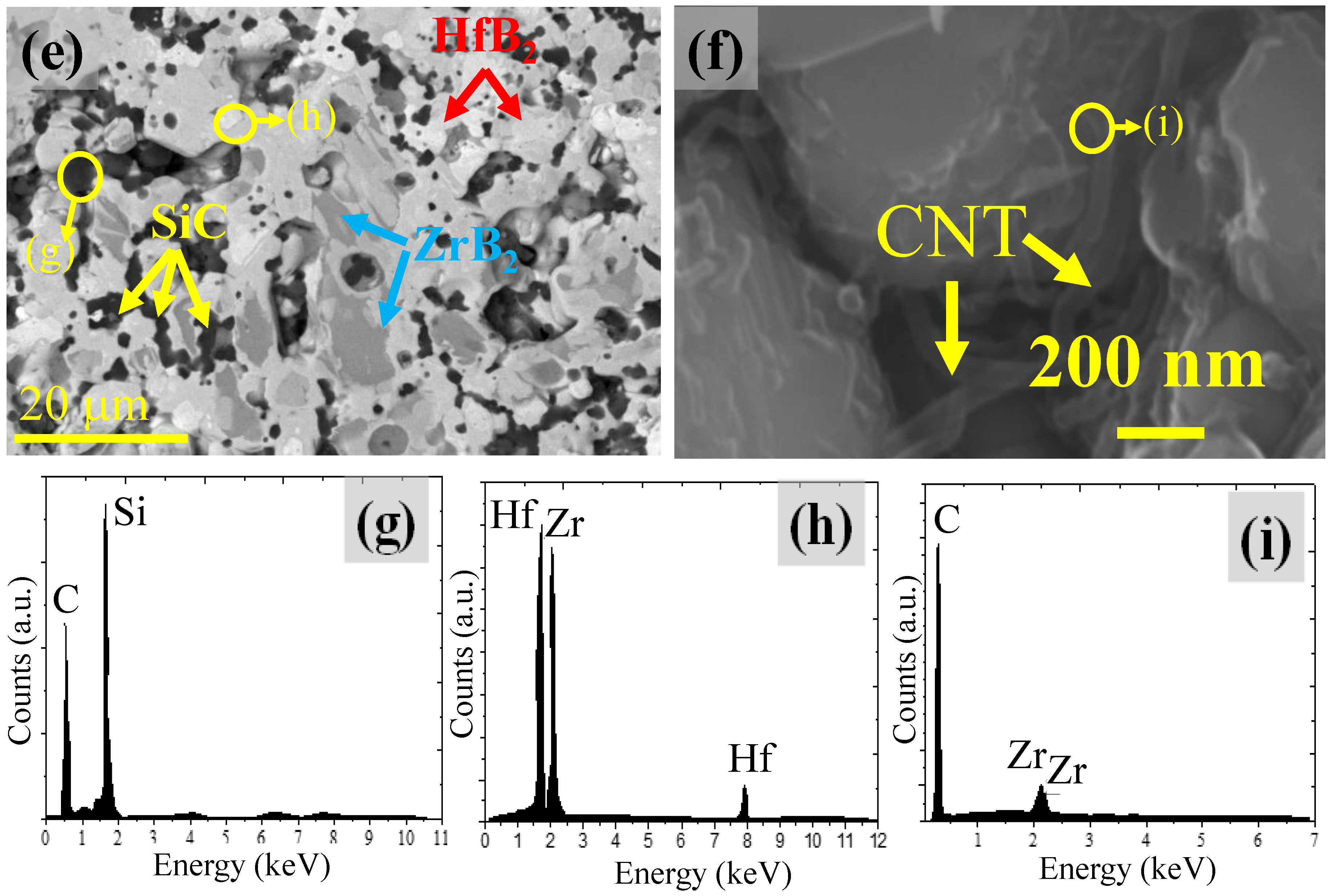
Figure 6.
Load vs. displacement curves for HfB2-ZrB2-SiC-CNT composites observed during instrumented indentation.
Figure 6.
Load vs. displacement curves for HfB2-ZrB2-SiC-CNT composites observed during instrumented indentation.

Figure 7.
Schematic illustrating the effect of microstructural evolution on the fracture toughness of HfB2-ZrB2-SiC-CNT: (a) H20S, (b) Z20S, (c) HZ20S and (d) HZ20S6C composites.
Figure 7.
Schematic illustrating the effect of microstructural evolution on the fracture toughness of HfB2-ZrB2-SiC-CNT: (a) H20S, (b) Z20S, (c) HZ20S and (d) HZ20S6C composites.


Table 1.
Nomenclature, relative densification and grain size of HfB2-ZrB2-SiC-CNT composites.
| Compositions | Sample ID | Theoretical Density (g/cc) | Archimedes Density (g/cc) | % Relative Densification |
|---|---|---|---|---|
| HfB2 + 20 vol % SiC | H20S | 9.04 | 9.04 | 100.0 |
| ZrB2 + 20 vol % SiC | Z20S | 5.51 | 5.46 | 99.0 |
| HfB2-ZrB2 (1:1) + 20 vol % SiC | HZ20S | 7.27 | 6.98 | 96.0 |
| HfB2-ZrB2 (1:1) + 20 vol % SiC + 6 vol % CNT | HZ20S6C | 6.92 | 6.85 | 99.5 |
Table 2.
Mechanical properties of HfB2-ZrB2-SiC-CNT composites. Here, ROM = rule of mixture, E = elastic modulus, re = elastic recovery, rd = resistance to deformation, KIC = fracture toughness and GIC = critical energy release rate.
Table 2.
Mechanical properties of HfB2-ZrB2-SiC-CNT composites. Here, ROM = rule of mixture, E = elastic modulus, re = elastic recovery, rd = resistance to deformation, KIC = fracture toughness and GIC = critical energy release rate.
| Sample ID | Hardness (GPa) | E (GPa) | re | rd | KIC (MPa·m0.5) | GIC (J·m−2) | |
|---|---|---|---|---|---|---|---|
| ROM | Experimental | ||||||
| H20S | 21.6 ± 0.2 | 23.4 ± 1.9 | 456 ± 10 | 0.560 | 0.440 | 5.2 ± 0.5 | 57.1 ± 3.3 |
| Z20S | 19.2 ± 0.3 | 23.6 ± 2.1 | 503 ± 13 | 0.656 | 0.344 | 5.7 ± 0.4 | 63.0 ± 2.1 |
| HZ20S | 20.4 ± 0.3 | 20.4 ± 4.9 | 425 ± 07 | 0.658 | 0.342 | 8.7 ± 0.8 | 176.8 ± 4.8 |
| HZ20S6C | 19.5 ± 0.3 | 28.1 ± 1.2 | 528 ± 08 | 0.666 | 0.335 | 10.2 ± 0.3 | 192.6 ± 1.6 |
Table 3.
Theoretical calculation of the coefficient of thermal expansion (CTE), modulus and residual stresses. Here, ROM = rule of mixture, HS = Hashin-Shtrikman, U.B. = upper bound, L.B. = lower bound, Em = elastic modulus of the matrix, Er = elastic modulus of reinforcement, σm = residual stress of the matrix, and σr = residual stress of the reinforcement.
| Composition | CTE (×10−6/K) | Modulus (GPa) | Residual Stress (MPa) | |||||
|---|---|---|---|---|---|---|---|---|
| ROM | HS Model | Em | Er | Hsueh’s Model σ0 | Taya’s Model | |||
| U.B. | L.B. | σm | σr | |||||
| H20S | 5.74 | 5.74 | 5.73 | 433 | 360 | 950.5 | 669.1 | −29.2 |
| Z20S | 5.42 | 5.42 | 5.40 | 366 | 555 | 878.5 | 806.3 | −32.8 |
| HZ20S | 5.58 | 5.59 | 5.58 | 394 | 185 | 591.3 | 214.5 | −40.2 |
| HZ20S6C | 5.36 | 5.36 | 5.34 | 485 | 650 | 176.4 | 139.0 | −42.8 |
© 2017 by the authors. Licensee MDPI, Basel, Switzerland. This article is an open access article distributed under the terms and conditions of the Creative Commons Attribution (CC BY) license (http://creativecommons.org/licenses/by/4.0/).
Share and Cite
MDPI and ACS Style
Nisar, A.; Balani, K. Phase and Microstructural Correlation of Spark Plasma Sintered HfB2-ZrB2 Based Ultra-High Temperature Ceramic Composites. Coatings 2017, 7, 110. https://doi.org/10.3390/coatings7080110
AMA Style
Nisar A, Balani K. Phase and Microstructural Correlation of Spark Plasma Sintered HfB2-ZrB2 Based Ultra-High Temperature Ceramic Composites. Coatings. 2017; 7(8):110. https://doi.org/10.3390/coatings7080110
Chicago/Turabian StyleNisar, Ambreen, and Kantesh Balani. 2017. "Phase and Microstructural Correlation of Spark Plasma Sintered HfB2-ZrB2 Based Ultra-High Temperature Ceramic Composites" Coatings 7, no. 8: 110. https://doi.org/10.3390/coatings7080110
Note that from the first issue of 2016, this journal uses article numbers instead of page numbers. See further details here.