Article

Thermal-Sprayed Coatings on Bushing and Sleeve-Pipe Surfaces in Continuous Galvanizing Sinking Roller Production Line Applications

1
Materials Science and Engineering, Shenyang University of Technology, Shenyang 110870, Liaoning, China
2
Dalian Huarui Heavy Industrial Special Spare Parts Co., Ltd., Dalian 116052, Liaoning, China
*
Author to whom correspondence should be addressed.
Coatings 2017, 7(8), 113; https://doi.org/10.3390/coatings7080113
Submission received: 29 June 2017 / Revised: 26 July 2017 / Accepted: 28 July 2017 / Published: 2 August 2017
(This article belongs to the Special Issue Manufacturing and Surface Engineering)

Abstract

:
This paper describes thermal spray techniques for making hard coatings on bushing and sleeve component surfaces. Specifically, plasma-arc welding was used to produce 5-mm thick Co-Cr alloy welding overlays on the bushing, while a high-velocity oxy-fuel spraying technique and laser re-melting technique were used to produce thinner coatings of Co-Cr-Ni+WC of about 1 mm thickness on the sleeve-pipe counterparts. The surface-treated components were then submerged in liquid zinc to study the corrosive behaviour of the surface coating and substrate. Both the scanning electron microscope and energy dispersive spectrometer analyses were used to study the microstructure and phase composition of both coatings and substrates prior to and after corrosion experiments. The results show that the microstructure of the bushing consists of γ-cobalt solid solution as well as the eutectic structure of γ-cobalt and carbides, which have good corrosive resistance against molten zinc. Meanwhile, the microstructure of the sleeve pipe consists of a Co-Cr solid solution with various forms of carbides, which displays the combined properties of toughness with good corrosive resistance to molten zinc.

1. Introduction

In the continuous galvanised zinc (Zn)-coating production lines in typical manufacturing factories, the rollers consist of sink rollers and tension rollers. Sink rollers are submerged in molten Zn baths and are subject to high-temperature corrosion in Zn solutions and continuous wear of the steel strip. The working environments of the rollers are extremely harsh [1,2,3,4]. Bushings and sleeve pipes are the main components on the sink-roller assembly, which are used as supports and rotation pairs for the sink rollers. Similarly, bushings and sleeve pipes are also subjected to high temperature, corrosion and abrasion. As a result, they generally have a very low in-service life, with its current working lifetime being approximately 15 days [5,6].
Sink rollers are normally made of 316L of stainless steel. In the past, the lifetime of sink rollers was usually about a week (or seven days) [7]. Recently, development has shown that with high-velocity oxy-fuel (HVOF)-sprayed carbon-deficient WC-12Co coatings, the lifetime of sink rollers had been extended to beyond 20 days. Nowadays, the challenge is how to extend the lifetime of the bushings and sleeve pipes, so that their service lives are compatible with that of the sink rollers. Bushings and sleeve pipes are also made of 316L of stainless steel. Studies have shown that the damage to these components was usually due to: (1) severe corrosion caused by molten Zn in the bath and (2) formation of Zn dregs that introduce severe wear problems on the interacting surfaces. The combined corrosion and wear eventually leads to rotation failure or fracture of the components [8,9].
To improve the service life of bushings and sleeve pipes as well as to reduce economic losses, many methods had been chosen to improve their wear resistance and anti-corrosion, such as selecting specialty materials, using a surface hardening process or other methods. The choice of materials usually includes high nickel (Ni)-chromium (Cr) stainless steel, Ni-based alloys or cobalt (Co)-based alloys for creation, but it obviously leads to higher manufacturing costs [10,11,12,13]. The method of material surface infiltration and centrifugal casting for the preparation of the bushings and sleeve pipes with a composite structure is a way to reduce the production cost and maintain excellent performance, but the manufacturing process is also very complex.
Surface modification and thermal spraying are effective methods for fabricating composite structures for bushings and sleeve pipes. These techniques had been effectively applied on the surfaces of strengthened sink rollers, which is the industrial standard today [14]. To date, however, little work has been done on the preparation of the surface hardening of bushings and sleeve-pipe surface techniques.
Therefore, this paper reports the recent works of surface modifications of Co-based alloy bushings and sleeves pipes using a combined welding overlay and the HVOF thermal spray technique. It also includes the surface properties of the coatings associated with their performance in a molten Zn work environment.

2. Experimental Procedure

2.1. Substrate Fabrication of Bushings and Sleeve Pipes

Using the Chinese industrial specifications, the bushings and sleeve pipes are made in-house at the Dalian Huarui Heavy Industrial Special Spare Parts Co., Ltd., Dalian, China, using 316L-type stainless steels. This is shown in Figure 1, which are the typical dimensions in the sink-roller assemblies of continuous galvanised Zn production lines in steel mills. Figure 1a shows that the bushing is a cylindrical-type of size 200 mm/100 mm × 100 mm, where the interacting surface is at its inner surface of the cylinder. Figure 1b shows that the sleeve pipe is also a cylindrical-type structure, with dimensions of 95 mm/70 mm × 105 mm, where the interacting surface is at its outer surface of the cylinder.

2.2. Coating Feedstock Materials

Varied materials are used for the bushing and sleeve-pipe surfaces, as shown in Table 1. The feedstock composition for the bushing is a Co-Cr-based welding alloy consisting of 61.25%Co and 30.19%Cr as well as other elements including 4.08% tungsten (W), 1%Ni, 1.48% silicon (Si), 0.5% manganese (Mn) and 1.5% carbon (C). The feedstock materials for the sleeve-pipe surface coating is a mixture of the Co-Cr-Ni alloy and WC powder, with a ratio of nearly 4:1. Molybdenum (Mo) was added to improve the corrosion resistance and Ni could improve the adherence of coatings. The composition is shown in Table 1.

2.3. Coating Fabrication

We aimed to achieve a 5 mm-thick coating for the bushing surface. With such a thick coating goal and its inner surface nature or non-line-of-sight (NLOS) surface, neither plasma spray nor HVOF spray systems can accomplish the task. Therefore, the plasma-arc-welding technique was used to prepare the coating. For the sleeve-pipe surface coating, we aimed to produce approximately a 1 to 2 mm-thick coating, with its line-of-sight (LOS) surface geometry nature. A HVOF spray technique and laser-melting technique were used to produce the coating.
For the bushing surface coating, a welding overlay technique was used to prepare the surface coating for the bushing. The welding torch model is BX-ZD-400A, made by Benxi Mechanical & Electrical Technology Co., Ltd., Shanghai, China. The plasma welding parameters are shown in Table 2.
For the sleeve surface coating, JP-8000 (Praxair, Danbury, CT, USA) HVOF spraying equipment was used to prepare the surface coating for the sleeve-pipe surface. Before thermal spraying, sample surfaces were sand-blasted using alumina-based sand with a mesh size of 30, followed by de-greasing using acetone. The spray parameters are listed in Table 3.
Since the sink roller is subjected to extensive loading (especially shear torque) during operation, the inner laminal structure and porosities of sprayed coating lead to poorer adhesion between the coating and substrate. Therefore, the laser-melting technique (LDF6000-100, Laserline, Mülheim-Kärlich, Germany) was used to re-melt the surfaces of the HVOF spraying coating, so that metallurgical coating bonding can be achieved and the splat boundaries between each layer are eliminated. The re-melting parameters by lasers are listed in Table 4.

2.4. Molten Zinc Corrosion Experiments

Regarding specimen preparation, using electrical discharge machines, the specimens were prepared by cutting the coated bushing piece into the dimensions of 15 mm × 15 mm × 10 mm (Figure 2a) and the coated sleeve-pipe specimen into dimensions of 15 mm × 15 mm × 12.5 mm (Figure 2b).
For the corrosion experiments, ceramic crucibles with aninner size of 92 mm × 118 mm (modelA5; and volume = 625 mL, Jintuo Experimental Equipment Co., Ltd., Changsha, China) were used. The samples were taken out at 72 h, 120 h and 168 h.

2.5. Coating Analysis

The coated and after-corrosion samples were cut into small cross-sections for metallography using epoxies for sample mounting. The mounted samples were then ground using a grinding machine (GPX200, Leco Corporation, St. Joseph, MI, USA), with the grinding started at a mesh size of 100, which was reduced down to a mesh size of 800. This was followed by polishing using a 1μm diamond slurry. An optical microscope (IA44+GX51RBB, Olympus, Tokyo, Japan) was used to analyse the coating thickness and porosity. The thickness of the coating was measured from the top of coating to the interface, with ten areas obtained to calculate an average length. The Vickers microhardness tester (HVS-1000, Shidai, Beijing, China) was used to measure coating hardness.
A scanning electron microscope (SEM; S3400, Hitachi, Tokyo, Japan) was used to analyse the cross-section samples to study the detailed microstructure of the coating and associated Zn-corrosive behaviour. An energy dispersive spectrometer (EDS; S3400, Hitachi, Tokyo, Japan) was used to analyse the overall coating composition and their localised phase identifications. In addition, X-ray diffraction (XRD; type 7000, Shimadzu, Kyoto, Japan) was used to study the phases of the coating prior and post-corrosion testing.

3. Results and Discussion

3.1. Coating Morphology, Phase Composition and Hardness

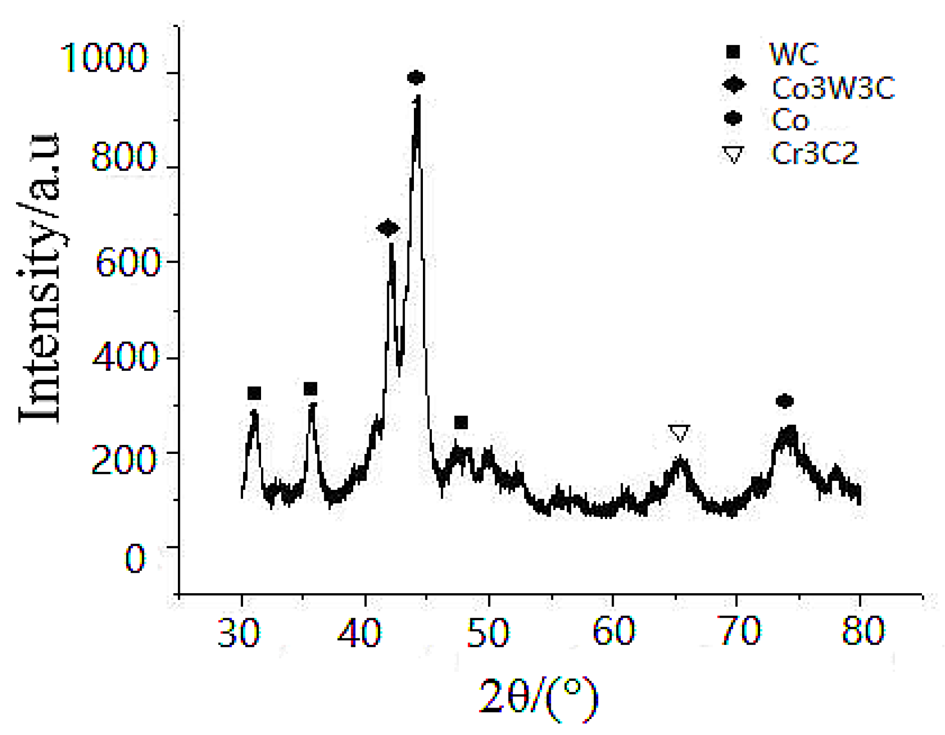
Regarding the bushing surface coating, the XRD spectrum is shown in Figure 3. Since no Cr and W phases were detected in the XRD spectrum, this probably indicates that Cr and W atoms are in the solid solution of the FCC Co structure, while the Cr-carbide phase is the hard phase dispersed in the Co-Cr matrix phase. The deposited Co-Cr alloy has a microhardness of approximately 530–580HV0.3. A Co-Cr (70:30 atomic ratio) would exhibit a microhardness of approximately 340–350HV0.3. This slight increase in hardness is probably due to the presence of the Cr–carbide phase-dispersion strengthening effect.
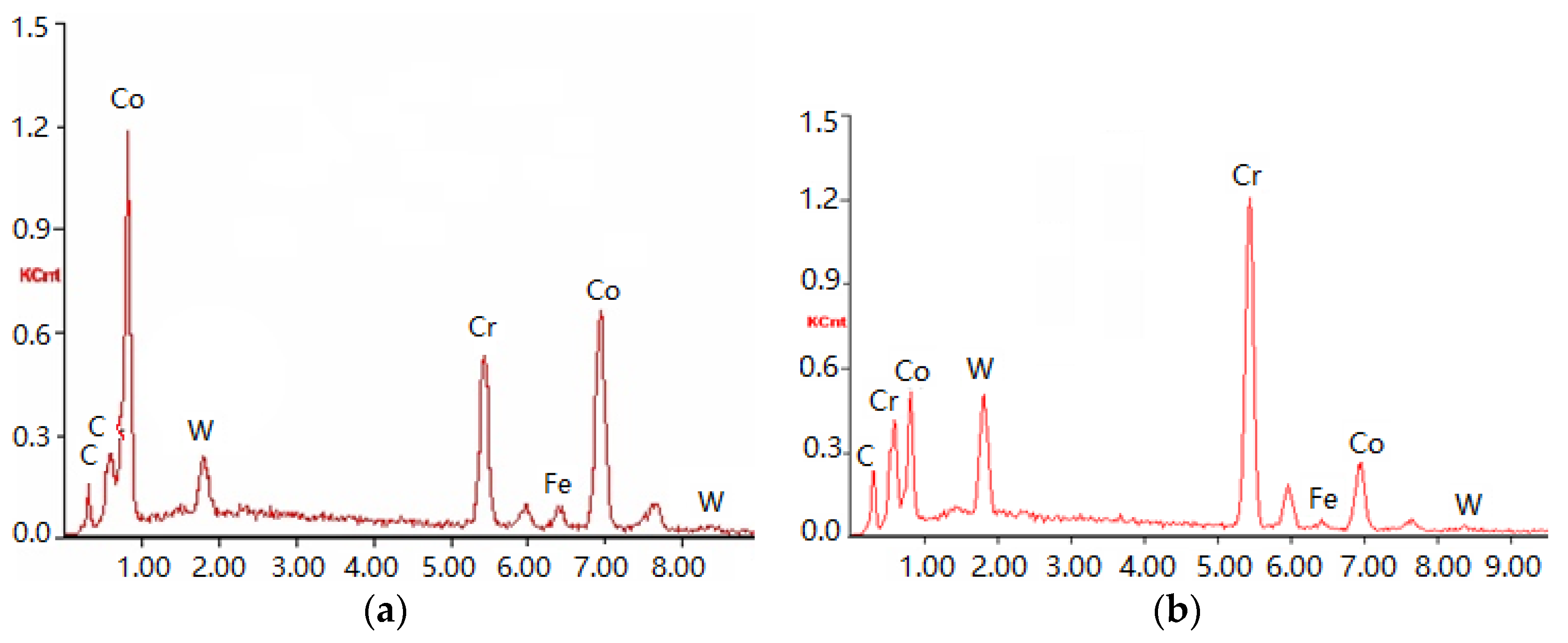
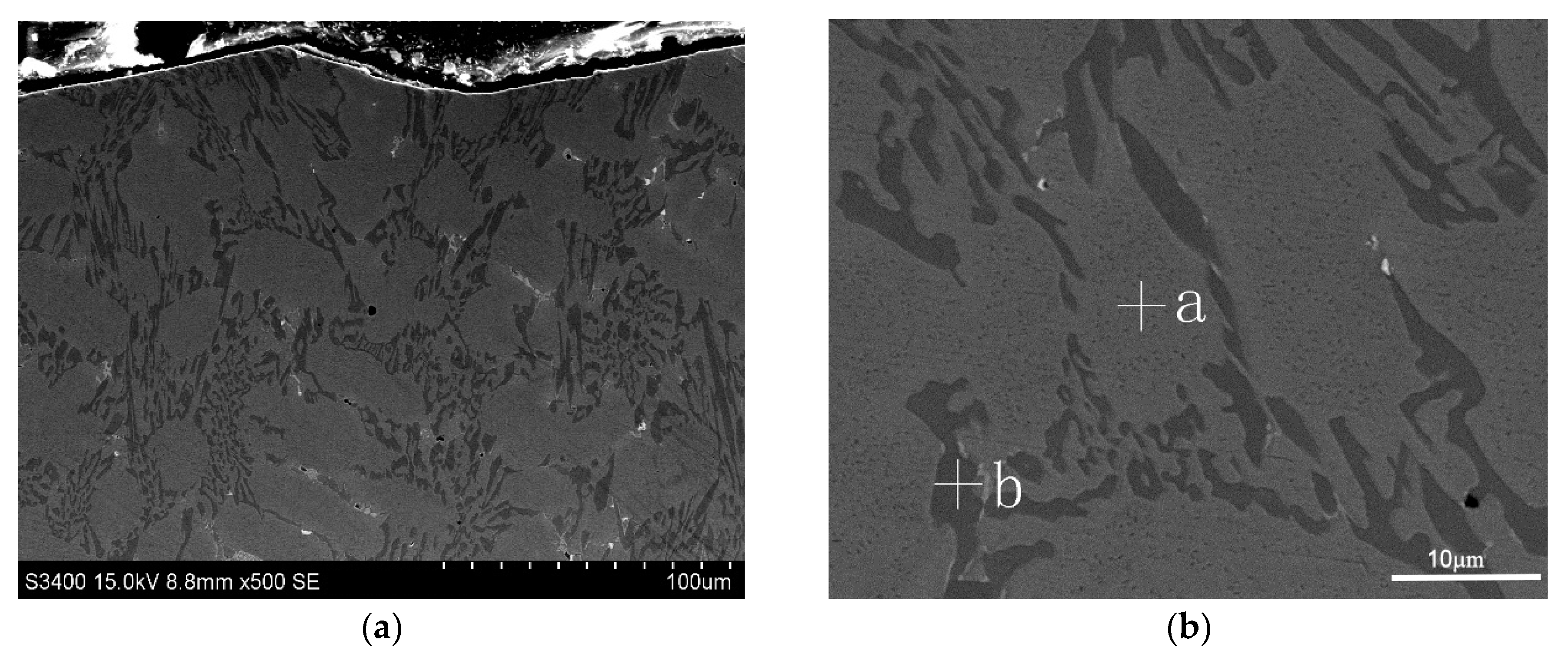
Figure 4 is an image of the welding overlay coating produced on the bushing surface. The two-phase microstructure is clearly shown, including a grey matrix phase and a dark bi-phase. To verify the chemical structure of the two distinct phases, EDS was focused on both the grey matrix Area a and the dark dispersion Area b with their spectra shown in Figure 5a,b, respectively. The quantitative analysis of the spectrum for these two areas is listed in Table 5. The hard-facing layer of the sink-roll shaft contains Co, Cr, W, C, Si and iron (Fe) elements, among others. The composition is the same as the powder in Table 1, but with the Fe element, which could not be found in the powder. This may be produced by a parent metal in the process of welding. The Co content is higher in the primary phase a, while the C is very low. This can determine that it is a γ solid solution phase (γ-Co), which forms some solid solution with a certain amount of alloy elements, such as Cr and W. In the primary phase at the grain boundary eutectic b, the C content is higher due to being concentrated with Cr and W, which shows that the phase is Cr7C3-type carbides with a γ-Co eutectic structure.
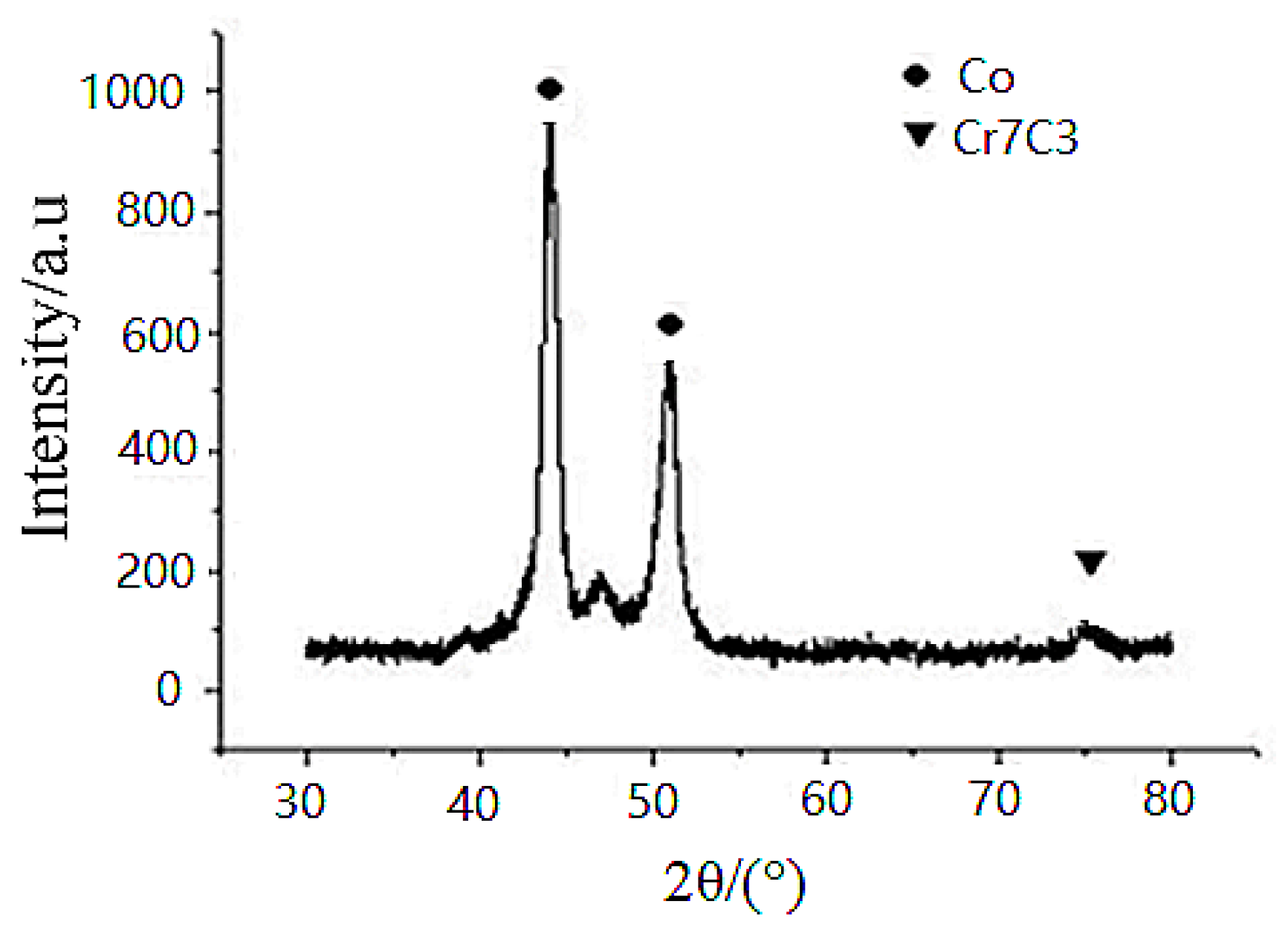
Regarding the sleeve-pipe surface coating, the XRD spectrum is shown in Figure 6 and the XRD spectra is quite complex. It indicated that the XRD spectra of the coating shows diffraction patterns of the following: (a) major FCC-Co phase with peaks of (111), (200) and (220) at 2θ angle of ~44°, ~51° and ~72°, respectively; (b) hexagonal W carbide (WC phase) peaks of (001), (100), and (101) at 2θ angles of ~31.5°, 35.6° and 48.3°, respectively; (c) η-carbide phase Co3W3C at 2θ angles of ~42°; (d) a minor Cr-carbide Cr3C2 phase identified at 2θ angles of ~65°.
The measured Vickers microhardness is approximately 900–1200HV0.3, indicating that the deposited sleeve surface is a complex Co-Cr-Ni alloy that has a co-existence of multi-phasic carbide phases.
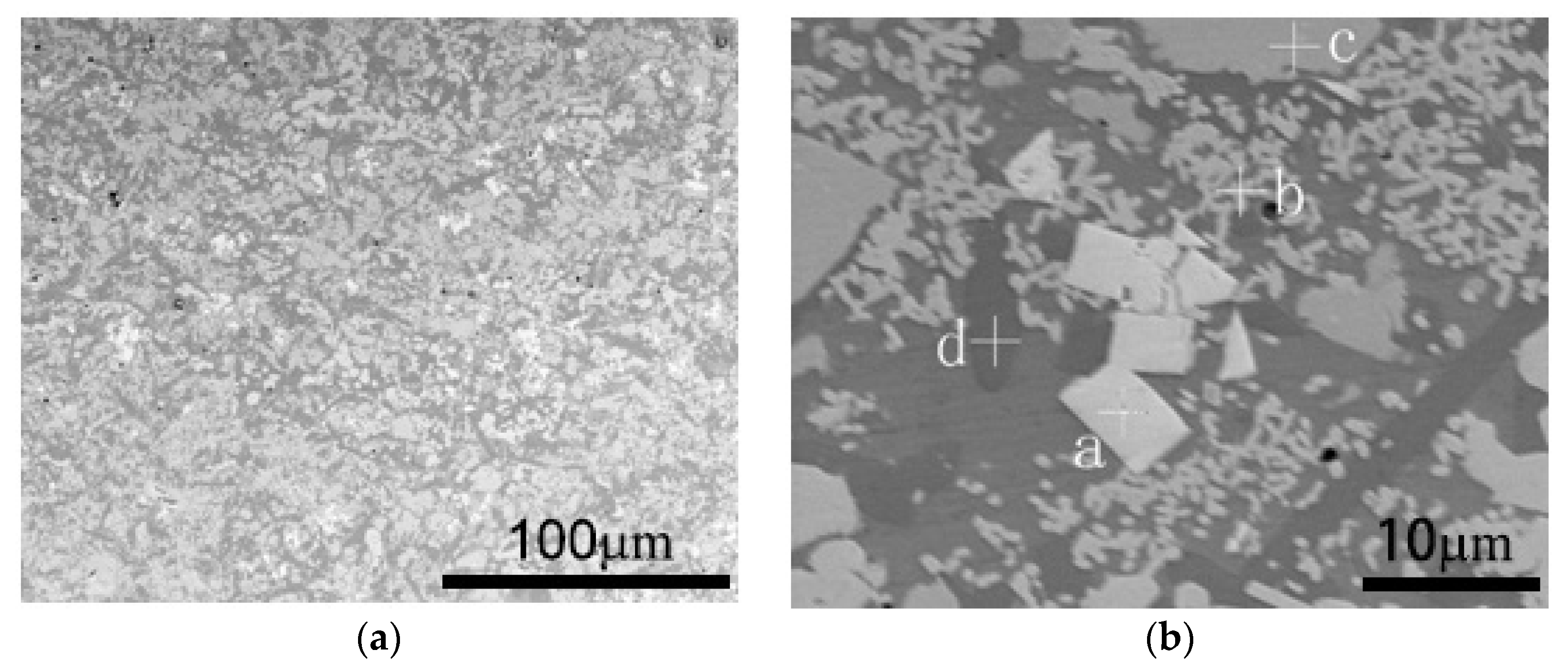
Figure 7 is an image of the post-laser treatment of the HVOF-sprayed coating produced on the sleeve-pipe surface. It is clearly a multi-phasic microstructure, which includes a grey facet large particulate phase (Area a), a grey contiguous smaller precipitate phase (Area b), a large irregularly shaped crystal phase (Area c) and a dark matrix phase (Area d). The EDS spectrum for all areas is listed in Table 6.
The above results show that the coating composition and microstructure are relatively complicated. The alloy system is a Co-Cr-Ni-W series, which contains a higher proportion of Cr and Co solid solutions as well as a certain proportion of W. There are three types of precipitated phase distribution. The zone in Area a is a white WC phase, which should belong to the mix with the WC powder. The Area b zone is a grey compound carbide phase including Cr, Co, Ni and W, which should belong to the Co3W3C phase. Furthermore, this compound contains some W elements in the γ-Co solid solution. The Area c zone has some small circular particles, which are distributed like “eggs”. Its composition is mainly C and W, meaning that it should belong to the WC or W2C compounds.

3.2. Corrosion of Bushing Surface Coatings

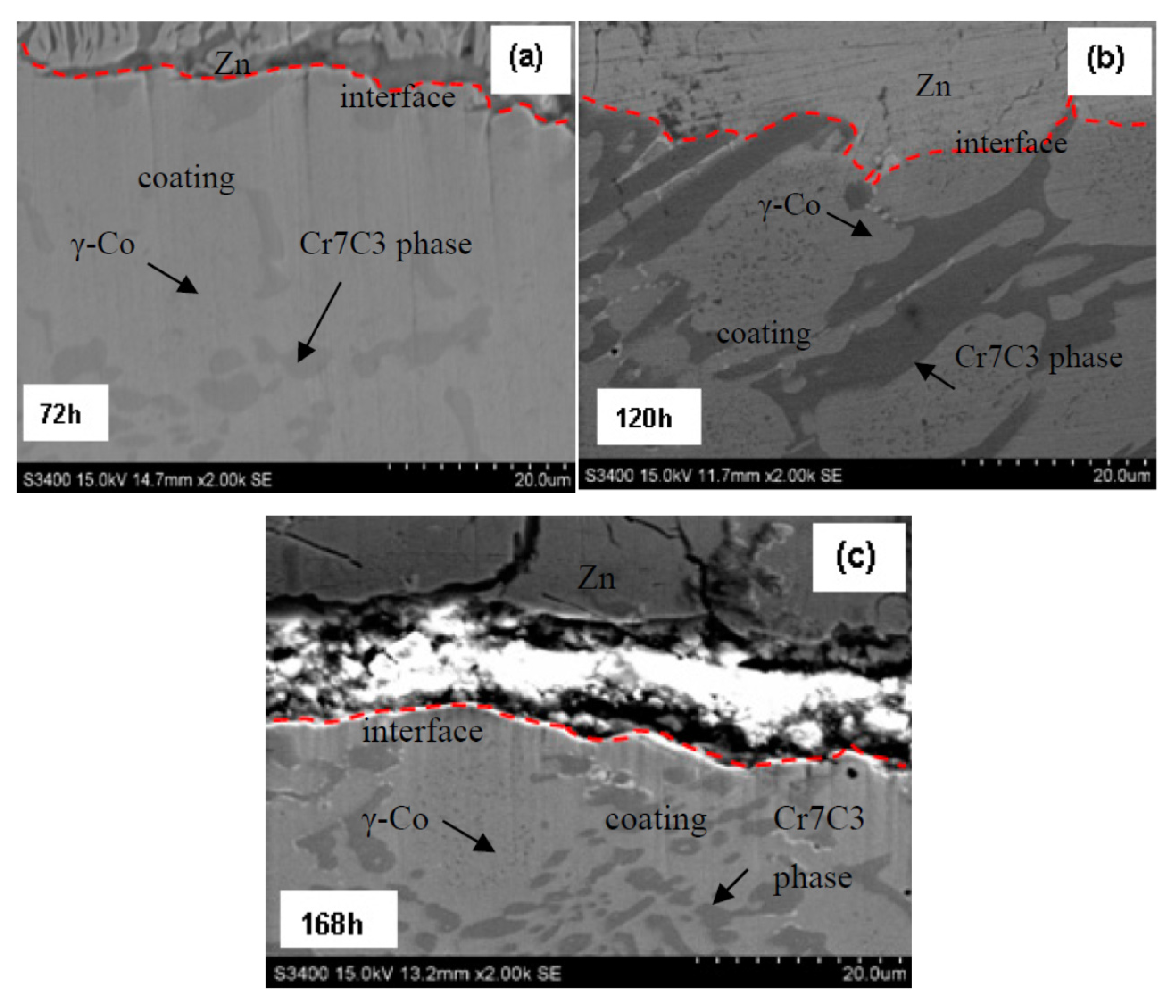
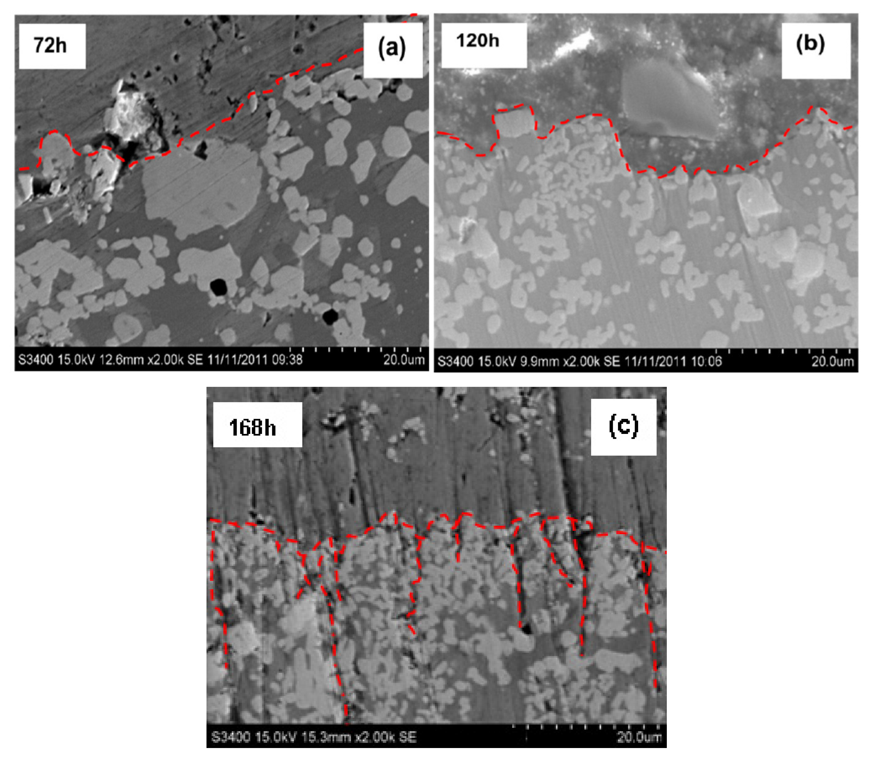
The coating has an original thickness of 5 mm. Their after-corrosion thicknesses are 4.475 mm for 72 h, 4.15 mm for 120 h and 3.65 mm for 168 h, which leads to a coating corrosion rate of 0.008 mm/h. The after-corrosion samples at the sampled times for the bushing coating for 72 h, 120 h and 168 h are shown in Figure 8a–c, respectively. Figure 8a shows two regions after the 72 h corrosion, including: (a) the top region with the molten Zn adhered onto the coating interface and (b) the bottom region with the coating. During the Zn corrosion, the coating morphology does not change, a new phase is not formed, while corrosion channels or cracks are not formed in the coating. In addition, the fact that there is no observed corrosion rate difference between the light-coloured alloy phase and the dark-coloured particulate phase (or eutectic phase) is likely to be the primary reason there is a uniform corrosion mechanism without the formation of cracks or interconnected porosity channels for the welding-overlaid bushing surface coating in the corrosion experiments.
Figure 8b shows the SEM image of the sample after 120 h of corrosion. There is some evidence that the matrix phase revealed a slightly higher corrosion rate than the dark-carbide particulate phase due to the presence of carbide particles protruding at the coating/molten Zn interface. However, the preferred corrosive resistance of the carbide particles did not result in a dramatic change in coating corrosion rate or the formation of cracks or corrosion channels in the coating. This is probably because the volume fraction of the carbide phase is too small to cause a dramatic corrosion rate difference in the material. This preferred corrosion difference is also evident in the 168 h corrosion sample, which is shown in Figure 8c for the protruding dark-carbide phase at the coating/molten Zn interface. Therefore, the fabricated bushing surface coating has a uniform corrosion mechanism and its corrosion rate is predictable for the sink-roller assembly in continuous galvanised Zn-coating production applications.

3.3. Corrosion of Sleeve-Pipe Surface Coatings

The HVOF sleeve-pipe surface coating after laser treatment has a thickness of 1 mm. Their thicknesses after corrosion are 0.8 mm for 72 h, 0.6 mm for 120 h and 0.3 mm for 168 h, which leads to a coating corrosion rate of 0.0042 mm/h. This can be divided into a corrosion rate of 0.0033 mm/h for the first 120 h and 0.0063 mm/h for the last 48 h from 120 h to 168 h in experiments. The corrosion rate of the HVOF sleeve-pipe surface coating without laser treatment is 0.104 mm/h for the first 72 h, with the failure of the coatings occurring after 120 h from the previous experiment.
The samples after corrosion at various times for the sleeve-pipe coatings at 72 h, 120 h and 168 h are shown in Figure 9a–c, respectively.
Similar to the bushing coatings, the 72 h corrosion experiment (Figure 9a) also shows two regions: (a) the top left region with the presence of molten Zn on the coating surface and (b) the right bottom region with the coating. At this stage of the experiment, the coating morphology does not change, no new phase is formed and no corrosion channels or cracks are formed in the coating. It appears that the large carbide particles may be more corrosive-resistant to the molten Zn due to the particulates protruding more at the coating/molten Zn interface. However, no obvious corrosion rate difference exists between the matrix alloy phase (slightly dark-coloured) and the white-coloured particulate phases. That can still classify it as a selective phase corrosion mechanism at this stage of corrosion for the HVOF-coated sleeve surface.
Figure 9b shows the SEM image of the sample after 120 h of corrosion. There is clear evidence that the coating exhibited severe molten Zn corrosion at this stage of the experiment. Both the top matrix phase and large carbide particulates were corroded away from the coating into the molten Zn. This resulted in smaller carbide particle particulates, which were not subjected to laser treatment, and the matrix coatings further towards the substrate being left behind. In addition, a noticeable higher corrosion rate of the matrix alloy phase was found when compared to the white carbide particulate phase. However, the preferred corrosion resistance of the carbide particles did not result in dramatic changes in the coating corrosion rate or the formation of cracks or corrosion channels in the coating. This preferred corrosion difference is obvious in the 168 h corrosion sample. This is shown in Figure 9c, where white carbide particulates protrude with severe cracks and channels having opened in the coating to expose the severe corrosion of the matrix phase. Following this, the corrosion rates are obviously higher for the matrix phase when compared to the white carbide particulates. In Co-Cr-Ni alloy coatings, the corrosion begins from the anodic microstructural phase. If the form of the anodic phase is continuous, such as a grain-boundary coating structure, a rapid penetration of the component could occur.
It should be emphasised here that the current report only involved the report of bushing and sleeve coating performance in molten Zn without subjecting an applied force. During the actual sink-roller operation in a production environment, conditions are much more aggressive and complicated, as the bushing and sleeve pipe will be subjected to molten Zn corrosion and surface wear. The coating wear mechanisms are quite complex. At the initial stage of coating wear, there will be two sliding surfaces with the liquid Zn acting as a lubricant and corrosive agent. As time goes on, corrosion, such as Co-Zn, Cr-Zn and surface wear debris (such as metals or alloys of Cr, Co and hard-phase carbides, including WC, Cr-C and η-Co-W-C), will be added to the surface, which further complicates the wear-and-tear process of the surface coating. We are now trying to improve the coating qualities and to plan the wear performance of the coating in both simulated and actual production environments. The results will be subsequently published.

4. Conclusions

  • The HVOF-coated sleeve-pipe sample exhibits a higher corrosive resistance of 0.0042 mm/h, when compared to the corrosive resistance (0.008 mm/h) of the welding-overlaid coated bushing sample. However, at the later stage of the corrosion, a preferred corrosion rate resulted, which caused cracks and corrosion channels in the coating. These are unfavourable for predicting the corrosion rate of components in applications.
  • The slightly dark-coloured matrix material consisted of metal-based elements, such as Co and Cr. These elements are reactive to molten Zn and form corrosive products, such as Co-Zn or Cr-Zn. However, alloyed metals or carbide particles are usually inert to liquid Zn.
  • The laser-treated top layer surface has more corrosive resistance than the untreated bottom layer of the sleeve surface coatings. This reveals that the laser treatment not only caused carbide particle growth, but also resulted in alloying of the matrix elements. This is the probable reason for its ability to also detect W and C in the dark-matrix phase in the EDS analysis. This dark-matrix phase is probably the dissolution of the WC phase into the matrix phase, which forms η-Co-W-C, a well-known Zn-corrosion resistance phase.

Acknowledgments

Thanks Xiao Dongshan from IFMTECH Co., Ltd. (Chongqing, China) for giving guidance and support at the experimental stage, providing so much valuable advice for the experiment. This work was funded by the National Natural Science Foundation of China (No. 51301112), Natural Science Foundation of Liaoning Province of China (No. 201602553).

Author Contributions

For this research article, G.Z. performed the experiments and wrote the manuscript; D.L. designed the experimental process; N.Z. analyzed the data; N.N.Z. assisted in paper review; S.D. reviewed the data.

Conflicts of Interest

The authors declare no conflict of interest.

References

  1. Yue, Q.; Zhang, C.; Xu, Y.; Zhou, L.; Kong, H.; Wang, J. Performance of flow and heat transfer in a hot-dip round coreless galvanizing bath. Metall. Mater. Trans. B 2007, 48, 1188–1199. [Google Scholar] [CrossRef]
  2. Wang, H.; Zhang, G.; Meng, X.; Duan, S.; Xu, C.; Guan, S. Zinc corrosion resistance and inactivation process of sink roll in hot galvanization. Chin. Surf. Eng. 2012, 25, 42–46. [Google Scholar]
  3. Abro, M.A.; Lee, D.B. Microstructural Changes of Al Hot-Dipped P91 Steel during High-Temperature Oxidation. Coatings 2017, 7, 31. [Google Scholar] [CrossRef]
  4. Matthews, S.; James, B. Review of thermal spray coating applications in the steel industry: Part 2–Zinc pot hardware in the continuous galvanizing line. Therm. Spray Technol. 2010, 19, 1277–1286. [Google Scholar] [CrossRef]
  5. Reichinger, M.; Bremser, W.; Dornbusch, M. Interface and volume transport on technical cataphoretic painting: A comparison of steel, hot-dip galvanised steel and aluminium alloy. Electrochim. Acta 2017, 231, 135–152. [Google Scholar] [CrossRef]
  6. Zhang, K.; Battiston, L. Friction and wear characterization of some cobalt- and iron-based superalloys in zinc alloy baths. Wear 2002, 252, 332–344. [Google Scholar] [CrossRef]
  7. Zhang, L. Thermal Spray Fe-Al Coatings Using for Continuous Hot Galvanizing Sink Rolls. Master’s Thesis, Dalian Maritime University, Dalian, China, 5 March 2007. [Google Scholar]
  8. Wang, L.; Zhou, Y.; Chen, G.; Rao, S. Analysis on dominant influencing factors of on-line life cycle in sink roll system and effective improved methods. Eng. Fail. Anal. 2015, 58, 8–18. [Google Scholar] [CrossRef]
  9. Guelton, N.; Lopès, C.; Sordini, H. Cross Coating Weight Control by Electromagnetic Strip Stabilization at the Continuous Galvanizing Line of ArcelorMittal Florange. Metall. Mater. Trans. B 2016, 47, 2666–2680. [Google Scholar] [CrossRef]
  10. Bae, K.T.; La, J.H.; Lee, I.G.; Lee, S.Y. Effects of annealing heat treatment on the corrosion resistance of Zn/Mg/Zn multilayer coatings. Met. Mater. Int. 2017, 23, 481–487. [Google Scholar] [CrossRef]
  11. Zhang, J.; Deng, C.; Song, J.; Zhou, K. MoB-CoCr as alternatives to WC-12Co for stainless steel protective coating and its corrosion behavior in molten zinc. Surf. Coat. Technol. 2013, 235, 811–818. [Google Scholar] [CrossRef]
  12. Tsipas, D.N.; Triantafyllidis, G.K.; Kiplagat, J.K.; Psillakia, P. Degradation behavior of boronized carbon and high alloy steels in molten aluminium and zinc. Mater. Lett. 1998, 37, 128–131. [Google Scholar] [CrossRef]
  13. Bahadormanesh, B.; Ghorbani, M.; Kordkolaei, N.L. Electrodeposition of nanocrystalline Zn/Ni multilayer coatings from single bath: Influences of deposition current densities and number of layers on characteristics of deposits. Appl. Surf. Sci. 2017, 404, 101–109. [Google Scholar] [CrossRef]
  14. Guo, J.; Zhang, C.; Ji, X.; Wan, W. Properties of coating by nano WC-Co used on sink roll. Therm. Spray Technol. 2016, 8, 25–29. [Google Scholar]
Figure 1. Schematic illustration of the typical dimensions of a sink-roller assembly at the continuous zinc galvanising production lines in steel mills: (a) bushing and (b) sleeve pipe.
Coatings 07 00113 g001
Figure 2. Schematic illustration of the specimen dimensions: (a) bushing with Co-Cr alloy coating and (b) sleeve pipe with Co-Cr-Ni+WC coating.
Coatings 07 00113 g002
Figure 3. XRD spectrum of bushing surface coating.
Coatings 07 00113 g003
Figure 4. Morphology of the deposited Co-Cr alloy coating on the bushing surface: (a) cross-section of the Co-Cr alloy coating; (b) position of EDS.
Coatings 07 00113 g004
Figure 5. Presence of atomic elements by EDS in (a) Area a, and (b) Area b.
Coatings 07 00113 g005
Figure 6. XRD spectrum of the sleeve-pipe surface coating.
Coatings 07 00113 g006
Figure 7. Post-laser treatment of the HVOF-sprayed coating on the sleeve-pipe surface: (a) cross-section of treated coating; (b) position of EDS.
Coatings 07 00113 g007
Figure 8. Microstructure of the bushing coating after corrosion tests at: (a) 72 h; (b) 120 h; (c) 168 h.
Coatings 07 00113 g008
Figure 9. Microstructure of the sleeve coating after corrosion tests at: (a) 72 h; (b) 120 h; (c) 168 h.
Coatings 07 00113 g009
Table 1. Compositions of the powder for both bushing and sleeve pipe.
No.Feedstock MaterialChemical Elements (wt %)
CSiMnCrMoWNiCo
1Bushing Coating1.501.480.5030.194.081.00Bal.
2Sleeve-Pipe Coating2.450.550.8929.500.4517.508.07Bal.
Table 2. Plasma welding operation parameters.
Current (A)Voltage (V)Gas Flow Rate (L/min)Cylinder Rotation Speed (r/min)
400–45035–4515–2560
Table 3. High-velocity oxy-fuel (HVOF) spraying operation parameters.
Fuel Flow Rate (L/h)Oxygen Flow Rate (m3/h)Powder Feeding Rate (g/min)Cylinder Rotation Speed (r/min)Gun Travelling Speed (mm/min)
21–2355–6065–70601000
Table 4. Re-melting operation parameters by lasers.
Power (kW)Ar Flow Rate (L/min)Focal Length (mm)Cylinder Rotation Speed (r/min)Gun Travelling Speed (mm/min)
2.52040060500
Table 5. Compositions of different areas in the produced bushing coatings by energy dispersive spectrometer (EDS).
No.Positions AnalysedChemical Elements (wt %)
CoCrWFeSiC
1General Area Average55304.04.21.41.7
2Grey Matrix Phase Area a63222.84.61.90.9
3Dark Phase Area b1263101.90.14.0
Table 6. Compositions of different areas in the produced sleeve-pipe surface coatings by EDS.
No.Positions AnalysedChemical Elements (wt %)
CoCrWNiC
1General Area Average28.015.044.08.03.7
2Grey Facet Large Particulates Area a90.09.3
3Grey Contiguous Smaller Precipitates Area b21.03.068.02.34.6
4Large Irregularly Shaped Crystals Area c17.010.058.07.75.5
5Dark Matrix Phase Area d3244.012.02.9

