Development of Sustainable Cold Spray Coatings and 3D Additive Manufacturing Components for Repair/Manufacturing Applications: A Critical Review


1
Faculty of Engineering Technology, University Malaysia Pahang, Pahang 26300, Malaysia
2
Department of Mechanical Engineering, University of New Brunswick, Fredericton, NB E3B 5A3, Canada
*
Author to whom correspondence should be addressed.
Coatings 2017, 7(8), 122; https://doi.org/10.3390/coatings7080122
Submission received: 30 June 2017
/
Revised: 2 August 2017
/
Accepted: 10 August 2017
/
Published: 14 August 2017
(This article belongs to the Special Issue Mechanical Properties of Nanostructured Coatings)
Abstract
:This review article presents the findings of a comprehensive state-of-the-art literature review of the scientific and technological progress of the cold spray process in the field of repair/remanufacturing using the concept of additive manufacturing. A thorough study was conducted on the potential of this technology to form (a) both thin and thick coatings; (b) the ability to fabricate 3D freeform components in a single process, while benefiting from reduced residual stress level compared to conventional thermal spray coatings processes such as high velocity oxy-fuel (HVOF) or plasma spraying. A systematic overview of the process technology, particularly focusing on the suitability of ceramic-metallic (cermet) composite particles used as feedstock in the deposition was conducted; further elaboration was made pertinent to particle impact and bonding mechanisms during the deposition.
1. Introduction
Thermal spray technologies have evolved from being “tough to regulate” to “controlled” processes since their first industrial applications in the early 1980s. Initially, the hard tool industry was the focus of thermal spray based coatings development. The process is generally described by methods in which coating is formed from melted or semi-melted droplets, with a starting material in the form of powder, wire or rod and is fed into a flame produced by a spray gun [1]. Depending on the nature of the energy source (kinetic and/or thermal) the deposited material can provide unique characteristics of the coatings or 3D additive manufacturing components. In particular, the coatings are used right across the spectrum of engineering industries most notably in the repair and manufacturing of components to enhance their surface properties, at the option of low-cost, lightweight, and sustainable investment. There are many examples of evolvement especially HVOF (high velocity oxy-fuel) and plasma spraying for producing coatings with low porosity and high adhesion [2]. These advanced coatings are used to give a predictable extension of in-service lifetime or to provide properties superior to untreated substrates for a more efficient performance in a particular application [3,4,5,6,7,8,9,10]. Advanced coatings are required to impart many characteristics to components; a few of the applications worth mentioning are wear resistance, corrosion resistance, heat resistance, oxidation resistance, electrical resistance, electrical conductance, fatigue strength, clearance control, self-healing, self-cleaning, non-stick, water repellent, anti-microbial, bio-compatible, bio-active, diffusion barrier, and high absorption capability [11,12,13]. These are often enabling disruptive technologies in a diverse range of products such as gas turbine engines, upstream pumps, drill bits, architectural glass, orthopedic implants, etc.
The energy source in thermal spray coating development is used to heat the feedstock to a molten or semi-molten state. The resultant heated particles are accelerated and propelled toward a prepared substrate by either process gases or atomization jets. Upon impact a bond is formed with the surface, with subsequent particles causing thickness build-up and forming a lamellar structure. The properties of the deposit may depend upon its density, the cohesion between the deposited particles, and particle adhesion to the substrate surface. For many materials, however, the use of high process temperature causes coatings to be internally-fractured due to decarburization, dissolution, and delamination at least [14]. For oxygen-sensitive materials for instance it is often required to produce coatings in an expensive vacuum chamber, thus limiting broader penetration of thermal spray into many commercial applications [15,16,17,18]. Traditional thermal spray processes are often found inadequate to use for temperature-sensitive materials and applications where coatings are required for repair/manufacturing with thickness of a few millimeters. These limitations were overcome by a new member of the thermal spray family, namely the cold gas dynamic spray.
Cold spray is an emerging process, discovered from a theoretical and experimental observation related to a supersonic two-phase flow (gas + solid particles) experimentation in a wind tunnel in 1990 [19]. It originated in the former Soviet Union by a group of researchers at the Institute of Theoretical and Applied Mechanics (ITAM) of the Siberian Branch of the Russian Academy of Sciences, who correlated the interaction of a two phase flow with the surface of an immersed body (particle) and demonstrated that it was possible to obtain coatings from solid particles at room stagnation temperature of the flow. Until that time, it was commonly accepted that particles needed to be heated to high temperatures ensuring their melting in the gas flow to obtain a coating, and that it was impossible to obtain a coating by spraying particles in the solid state. Since then, the technology has enjoyed few iterations and by far the biggest success has been largely embodied by the spraying of metallic/metal alloy particles with the help of high velocity particle impingement [20]. Later on many patents were filed and granted using this process and for the development of the spray equipment for deposition of variety of materials such as metals, alloys, mixtures, and polymers [21].
There is a very basic difference between conventional thermal spray techniques and the cold spray process. Thermal spray techniques require both thermal and kinetic energies for the coating formation, while cold spray uses only kinetic energy, as depicted in Figure 1.
In cold spray there is no melting of particles taking place as the process temperature stays below 800 °C, while in HVOF this can go up to 3000 °C. Softer materials (easier to plastically deform) and materials that have smaller heat capacities (easier to achieve shear instability) have so far benefited from the use of this technology. This distinctive feature enables it to be used for substrates and powders alike which are temperature sensitive (such as nanostructured and amorphous) and oxygen sensitive (such as aluminum, copper, titanium, etc.). On the other hand, high velocity particle impingement (as high as 1200 m/s) in the absence of thermal energy in the solid state produces uniform coatings with negligible porosity and minimal residual stresses. Cold spray is one of the most favorable processes for such applications in which non-porous and uniform coatings are required without allowing substrate heating [22,23]. Therefore, this new combination of low process temperature along with high particle kinetic velocity demands an appropriate and systematic review of the current state-of-the-art. Since application areas are ever more expanding as process outputs surpass the imagination, this review paper will keep its focus on the growing demand of cold spray coatings and 3D additive manufacturing components in the repair and manufacturing industries. The current work is founded on the “process mapping approach”, in the context of the present development and future needs, implying cermet based high pressure cold spray coatings and components.
The structure of the paper is as such: Section 2 deals with the principle of cold spray process technology, which has a natural evolution to the proposed understanding of the mechanisms in particle impact and bonding on prepared substrates, and as sketched in Section 3. Section 4 describes the extent of parameters and their impact on generating the optimal bonding/impact mechanisms. Section 5 maps the coatings and their corresponding applications at the current time, which will give rise to the need for novel coatings using cermet particles in the cold spray process in Section 6. Section 7 shows the high benefit of using cold spray technology over other thermal spray methods. The review is then followed by highlighting the potential of the technology in areas such as additive manufacturing, repair, and biofouling prevention in Section 8, as well as functional coatings development in Section 9. Section 10 extends the discussion into metamaterials derivation by use of the cold spray principle. Finally, Section 11 concludes the review shedding light on future challenges.
2. Process Principle of Cold Spray
The basic principle of the cold spray process is straight-forward: a high velocity (300 to 1200 m/s) gas jet, formed using a deLaval or similar converging/diverging nozzle, is used to accelerate powder particles (1 to 50 μm) and spray them onto a substrate, located approximately 25 mm from the exit of the nozzle where they impact and form the coating. The kinetic energy of these particles rather than high temperature helps to retain the plastic strain energy from the collision as heat which increases the temperature of the substrate and softens the material, thereby reducing the rate of strain hardening. This effect is also known as “adiabatic shear instability”. The resultant deposit will have experienced significantly reduced deleterious shortcomings such as high temperature oxidation, evaporation, melting, crystallization, residual stresses, and gas release. In this process, powder particles are accelerated by the supersonic jet at a temperature that is always lower than the melting point of the material, resulting in the coating formation from particles in the solid state and hence no melting and solidification process is experienced by the powders [24,25]. A schematic of a representative cold spray gun is exhibited in Figure 2.
Pressurized gas (generally air, nitrogen, and helium) is heated usually with electrical energy to temperatures ranging from 300 to 800 °C and then passed to a converging/diverging nozzle to create a supersonic gas jet. However, unlike conventional thermal spray processes, the gas is heated to increase its velocity to supersonic values while pushing through the converging/diverging nozzle. The supersonic velocity is reached due to the change of the Mach (, where is the gas velocity and the sound velocity) number along the nozzle. At the convergent part of the nozzle , in the throat , and in the divergent part . As the gas velocity increases, the gas temperature and pressure decrease, as per the conservation of energy law the product of “velocity” and “temperature” must be preserved. Since the gas expansion is followed by a temperature decrease, which can in some cases even be below room temperature, the process obtained the name of “Cold Spray”.
Figure 3a,b presents schematic and actual photograph of a cold spray gun developed by “Kinetics of Switzerland”, respectively. In this gun, the gas moves through a deLaval nozzle, shown in Figure 3c.
Pressure, and inlet and outlet temperatures are measured using sensors. The gas is distributed through a heater module with 22 kW output. The powder/carrier gas mixture is injected axially into the gun and fed through the appropriate pre-chamber for the chosen feedstock material towards the de Laval nozzle. Powder is accelerated by the expanding gas and impacts the substrate as solid particles. Current cold spray equipment is overwhelmingly dependent to work with materials with relatively low melting point and low mechanical strength such as Zn, Al, Cu, Ni, and their alloys, as they have a low yield strength and exhibit significant softening at elevated temperatures. Therefore, low pressure cold spray (LPCS) in which particles are injected in the diverging section of the spray nozzle from a low pressure gas supply system is sufficient. The nozzle design in this case is restricted to a relatively low exit Mach number (usually <3) and the inlet pressure is restricted to below 1 MPa to allow atmospheric pressure to supply powders into the nozzle, thereby generating a particle velocity of only up to 600 m/s. On the other hand, the high pressure cold spray (HPCS) can generate particle velocities as high as 1400 m/s thanks in part to the use of low molecular weight gases, such as nitrogen and helium as propellant. HPCS utilizes a pressure of up to 5 MPa with axial injection of feedstocks that are heated up to a maximum temperature of 1100 °C in the spray gun housing. The high kinetic energy and the high degree of deformation during the impact on the substrate is connected with it enabling the manufacture of homogeneous and very dense coatings [26]. The range of coating thicknesses varies from just a few hundredths of a millimeter up to several centimeters. The particles’ high impact speeds promote rapid spreading, plastic deformation, and the deposition of a highly dense layer of particles. Bonding between the deposited particles is typically metallurgical, coupled with mechanical interlocking. The absence of high temperature particle heating during the deposition process eliminates oxidation, promotes retention of the properties of the original feedstock particles, induces low residual stresses in the coating, permits deposition of thermally sensitive materials such as polymers, and facilitates deposition of highly dissimilar materials such as cermets. Research into the spraying of cermet composite particles and high-density particles is lacking and as such there are no proven process parameters that will work with them [27].
3. Bonding Mechanism and Impact Phenomena in the Cold Spray Process
The formation of a coating is obtained by the transformation of the kinetic energy of the particles into mechanical deformation and thermal energy, occurring on the order of 10−7 s. It was suggested that the bonding is largely due to mechanical interlocking, where the substrate physically entraps the particles. At high impact velocities, the outer region of the particle that impacts the substrate experiences severe plastic deformation and as a result a large temperature increase. It is thought that this temperature spike results in local melting of the particle, where the melted material forms a strong bond with the substrate [28,29]. The particle-particle and particle-substrate interaction due to thermal softening is hypothesized to give rise to local adiabatic shear instabilities [30]. According to adiabatic shear instability theory when a particle impacts in cold spray, the particle/particle or the particle/substrate interfacial areas experience an extensive localized deformation (i.e., shear deformation) during impact which leads to disruption/instability of the thin oxide surface films. This empowers an intimate conformal contact between the particle and the substrate or the previous deposited layer, and thus forms bonding [28,29,30,31]. Better illustration of this theory can be understood with the help of the following points: (1) plastic strain energy from the collision is retained in the system as heat increases the temperature of the substrate and softens the material. This reduces the rate of strain hardening; (2) flow stress (instantaneous stress required to plastically deform something) reaches a maximum at a certain strain value then begins to decrease with additional strain; (3) under real conditions (i.e., fluctuating stress, strain, temperature, microstructure), strain softening (shear, heat) becomes localized. In this case of localization, the flow stress quickly drops to zero (i.e., plastic deformation occurs very easily in a narrow region surrounding the particle/substrate interface), causing injection of an interfacial jet (similar to a splash of an object hitting water) made of the same, now heavily deformed, material as the particle; and finally (4) the jet removes oxide film on the particle and substrate, enabling direct contact of the metallic surfaces thus promoting bonding along with the relatively high contact pressures and adiabatic softening of the interfacial region. However, a more universally-accepted bonding mechanism can be understood by dividing the interaction phenomena into four distinct stages [32], as depicted in Figure 4 below.
- In the initial stage, a thin film of particle material (i.e., monolayer) is deposited on the substrate. This stage is characterized by the direct interaction of particles with the substrate and depends very much on the degree of substrate surface preparation, as well as on the properties of the substrate material. This stage includes the time of surface activation (induction time) during which erosion instead of deposition will occur.
- In the second stage, particle deformation and re-alignment will occur. A layer of finite thickness builds up. As densification intensifies, the material at the point of contact is displaced, the contact area enlarges in size and material flows into the inner particle voids, which is equivalent to a “peening” effect.
- The third stage is characterized by the formation of a metallurgical bond between the particles and the void reduction.
- Stage four corresponds to further densification and work hardening (due to the peening effect) of the coating.
In actual fact, the surfaces of metallic parts are rarely flat and are generally covered with an oxide layer. Therefore, to produce solid state bonding the surface oxide layers must be removed to allow contact of the fresh metallic surfaces. This can be achieved by compressing and stretching the interfacial region via plastic deformation, as shown schematically in Figure 5. Bonding in cold spray is considered to identify with such a type of interfacial deformation as shown in Figure 5, which prompts the breakup of surface oxide layers and enables the contact of metallic surfaces at atomic level. Thus, the oxide layer should be considered as a geometrical constraint and not an “energy barrier” to metallurgical bonding [28].
It is generally accepted that the adhesion strength of the particles in cold spraying is only due to their kinetic/mechanical energy at impact, that is often abundant but not up to the energy needed to melt the particle (as such a “solid-state” deposition method). Referring to Figure 4, it has been explained that the forced mixing between the copper deposited (lighter sections) and aluminum substrate (darker section) copper deposit establishes a firm bond between the deposited particle (copper) and substrate (aluminum). The intense mixing presented can be achieved by deep-impact penetration of the copper particles on the substrate material i.e., aluminum. Furthermore, there is a least amount of particle velocity needed to accomplish the impact nature of bonding, since an adequate amount of mechanical/kinetic energy is requisite to plastically deform the solid particles [30]. Figure 6 further shows the presence of material adjacent to the interface behaving like a viscous fluid, resulting in the formation of interfacial waves, roll-ups, and vortices [31], in which the impact of a 20 µm spherical copper particle on an aluminum substrate was recorded at a particle velocity of 650 m/s.
Particle bonding in cold gas spraying can be affected by numerous factors connected to geometrical parameters of the substrate, e.g., contact surface area, the depth and width of crater, and factors associated with thermomechanical parameters, including plastic strain, flow stress, pressure, and temperature at the interface. All these are influenced by particle velocity. It would therefore be reasonable to assume that at velocities near the critical velocity, they also would reach a critical value, or would they show a change in trend in their variation with velocity [30]. It was also reported that the cold spray process depends primarily on the right selection of particle velocity, somewhere between particle critical velocity and erosion velocity. The erosion velocity must be less than the particle velocity so as to produce adhesion action. Many researchers have worked on developing and modifying the theoretical models for predicting critical velocity in the cold spray process in terms of different material properties such as particle density, impact temperature, melting temperature, ultimate tensile strength, and hardness of the particle [28,29,30,32,33,34,35,36,37,38].
4. Cold Spray Process Parameters
The deposition growth rate and the final coating properties, in the cold spray process, are influenced by several input parameters, namely, particle impact velocity, spray angle of the gun, standoff distance, molecular weight of the carrier gas, substrate surface roughness, particle morphology and size distribution, feed rate, as well as particle and gas temperatures. Feedstock deposition efficiency is one of the most important characteristics of cold spray coatings, as well as of all other methods of powder coatings. It is a measure of coating thickness divided by the number of passes by the spray gun. The influence of the most relevant parameters in obtaining deposition efficiency will be described in this section.
4.1. Effect of Particle Impact Velocity
Particle velocity at impact on the substrate has a key parametric significance in the cold spray process. For each material there exists a critical particle velocity. Only the particles reaching a speed over the critical velocity can be deposited to produce a coating. To better understand this phenomenon, Figure 7 shows a typical plot of the induction time as a function of particle impact velocity. The induction time (also known as “incubation time”) represents the time between the beginning of surface treatment by the flow of particles and the beginning of particle adhesion to the surface.
From Figure 7, the induction time is further segmented into three distinct zones (i.e., Section-I, -II, and -III) of interaction between particle and substrate, in account of two different particle velocities, and . Section-III represents the region where particle velocity is higher than (850 m/s), and particles adhere to the initial surface without any delay [31]. When the particle velocity is between and (Section-II), particles cannot adhere instantly to the initial surface. The adhesion starts with some delay that corresponds to the time during which the surface state is changed due to its “treatment” by the first impinging particles and appropriately, Section-II is usually called a “delay adhesion zone”. Since the induction time is inversely proportional to the rate of particle influx in the gas flow, in Section-I, which corresponds to values of velocity lower than (550 m/s), only erosion occurs. That is, particles do not adhere to the surface regardless of the treatment time. This is known as “critical velocity” a value at which transition begins from erosion to coating formation.
Now from the above specification, it is clear that particle velocity plays a key role in the cold spray process, and therefore, it is important to understand how this parameter is affected by the propelling gas pressure and temperature in the pre-chamber. Using low molecular weight gases (such as helium) and heating them it is possible to achieve a particle velocity near the gas velocity; however, it is desirable to avoid the use of high pressures and temperatures of the gas. In an early study founded on computational modeling, Stoltenhoff et al. demonstrated that the particle temperature is almost independent of pressure, but the particle velocity increases by 15% if the pressure is doubled (from 1.5 to 3 MPa) [39]. Further, a change in gas temperature at a constant pressure of 2.5 MPa increases the particle velocity by 25% when the temperature is doubled (from 300 to 600 K) in a low pressure cold spray process, keeping all other parameters (such as nozzle geometry, particle characteristics) unchanged. At higher temperatures (above 793 K), the increase in particle velocity is less pronounced because of the decrease in gas density.
4.2. Effect of Particle Morphology
Lower range particle size distribution works best to achieve a suitably high particle impact velocity in the cold spray process. This is attributed to the fact that gas/particle momentum transfer or particle expedition imparted by gas is proportional to , predicted by Newton’s laws of motion and surmising a spherical particle, where is the diameter of the particle to be expedited. Consequently, higher expedition and therefore higher impact velocity is to be expected when utilizing a powder with a more miniscule particle size distribution, as long as the jet Mach number is surrounded by values close to 3. Higher particle velocity is further connected with the drag force acting on a particle. Referring to Equation (1), the drag force () is calculated by [40]:
where is the propellant gas mass density, is the relative velocity between the propellant gas and the particle, is the particle projected surface area, and is the particle drag coefficient. An increased drag coefficient will lead to an increased drag force acting on the particle and so to a higher particle velocity.
On the other hand, the friction drag, caused by the friction of propellant gas against the surface of the particle that is moving through it, for spherical and non-spherical particles is liable to be kindred. For example, the non-spherical particle will have a higher surface area in contact with propellant gas and, hence, a higher drag coefficient. As a result, a more astronomically immense drag force will be applied to the non-spherical particles, promoting higher particle velocity at cessation of the expedition zone of the nozzle.
Another important consideration about the morphology of the powder is that a non-spherical particle with a rough surface and irregular features will have different contact behavior during impact. Ajdelsztajn et al. [41] showed that the localized shear deformation at the particle boundaries during impact promotes an intimate contact between particles and helps the formation of a particle/particle metallurgical bond. This will be enhanced by a larger surface area of the irregular particle morphology, increasing particle/particle interaction in the deformation process. Further, the irregular morphology will increase the stress concentration during impact due to the fact that the load cannot be uniformly distributed as may observed in spherical particles.
4.3. Effect of Powder Feed Rate
Coating thickness may vary depending on the mass flow rate at which the powder is fed into the carrier gas stream. Coating thickness will grow with the increase in powder feed rate at a linear rate up to a certain thickness value. Thereafter particles impacting the surface of the substrate may cause excessive residual stress formation, which in turn may initiate the coating to peel off. Usually, this effect is compensated or reduced by increasing the gun traverse speed [42].
4.4. Effect of Spray Angle
Referring to Section 4.1, particles possessing velocities higher than the critical velocity at normal impact are deposited on the substrate. However, with the decrease in spray angle, the normal component of particle velocity will decrease. As such, when its value becomes less than the critical velocity the particle will not deposit on the substrate. In the event of an impact at an off-normal angle, the particle impact velocity can be decomposed into normal and tangential components with respect to substrate, as shown in Figure 8. This has been further evidenced by research that has shown that the maximum deposition efficiency was achieved at spray angles ranging from 80° to 90° for copper, and 70° to 90° for titanium [41]. It can be seen from Figure 9 that on using the mentioned angle range, the spray angle is practically found to have much less influence on the deposition efficiency. Yet, on further decrement in the spray angle from the mentioned range, the deposition efficiency decreased to a point at which no particle deposition was occurring (40° for copper and 50° for titanium).
Wang et al. [43] modelled the effects of spray angle on bonding mechanism. Figure 10 depicts the results of their work, which concluded that: (a) bonding strength increases with decreasing spray angle from the normal direction (90° spray angle), and the maximum bonding strength is achieved at 45° spray angle; however, the deposition efficiency and strength of the bulk deposit material decreased with decreasing spray angle.
4.5. Effect of Standoff Distance
The standoff distance has a pronounced effect on the impact velocity of powder particles. It was observed that when the distance increases from 10 to 50 mm, the impact velocity increases from 420 m/s to 550 m/s [44] on copper particles of 10 µm in diameter in a low pressure cold spray. The phenomenon was described as “shock wave attenuation”, due to the fact that viscous forces in a two-phase flow become more significant with increasing distance. This leads to a decrease in the Mack number in the vicinity of the substrate, and the lower the Mack number is, the weaker the shock wave is needed for the flow to pass a subsonic regime. The drag forces decrease thereby, and the impact velocity increases. This favorable effect disappears when the distance becomes greater than 50 mm and the shock wave vanishes. More effectively, at small standoff distance, when the strength of the bow shock (it is known that the particle velocity increases outside the nozzle and that the particles may lose velocity during the flight, although this velocity can be further reduced due to the shock wave resulting from the previous particles impacting the substrate) increases, the deposition efficiency reduces. While at large standoff distance, when the bow shock has disappeared the deposition can continue unhindered.
4.6. Effect of Particle, Substrate and Gas Temperature
The physical characteristics and tribological-mechanical properties of the coatings, as well as the deposition efficiency can be significantly enhanced by increasing the initial temperatures of particle and substrate [45]. This observation is supported by the fact that higher initial particle temperatures result in lower critical velocities since the material is already softer at higher temperatures, and that less kinetic energy is needed to heat particle surface areas by plastic deformation. Increased deposition efficiency is reported by Li et al. [46] with higher carrier gas temperature. In the study, titanium feedstock particle was injected in an LPCS process. No particle deposition occurred for temperatures of nitrogen gas below 155 °C, the deposition efficiency increase thereafter steadily up to 215 °C.
Further, temperature increase may affect the deposition efficiency and coating properties in different ways: (a) with the increase in process gas velocity the particle impact velocity will rise with increasing stagnation temperature; (b) by introducing a higher gas temperature or by preheating the powder and/or substrate the material thermal behavior (e.g., elastic and plastic properties) can be changed. Increased material temperature could enhance thermal softening which is important for the bonding mechanism, and also potentiate chemical reactions that may induce adhesion in the coating-substrate system.
4.7. Effect of Surface Condition
High substrate surface roughness (going from polished to grit-blasted) deposition efficiency of metallic powders increases because the impacting particles become deformed more severely on a roughened surface as compared with the smooth surface of the substrate, thereby promoting mechanical interlocking. Mechanical interlocking is considered a leading theory surrounding cold spray coatings which is promoted by particle impingement on the substrate surface. It is thus reasonable to assume that an increased substrate roughness would further enhance bonding as it presents a greater array of nooks and recesses in which cold spray particles can be lodged. These particles are then subjected to additional compaction as successive particles impact on the substrate. For surfaces with low roughness, the first particles to impact would have little surface area available to which to bind, resulting in weaker bond strengths. These particles thus have a greater difficulty adhering to the substrate, resulting in an initial reduction of deposited mass [47].
5. Coatings by Cold Spray Process
Surface coatings are used right across the spectrum of manufacturing and engineering industries to enhance the surface properties of components that can be made from low-cost, lightweight, or sustainable materials. This allows the designer to create cost-effective, high-performance parts with functionalized surface characteristics exactly for the required use. These are often enabling disruptive technologies in a diverse range of products such as gas turbine engines, drill bits, architectural glass, orthopedic implants, to name only a few. Surface engineering and advanced coatings are used to give a predictable extension of in-service lifetime or to provide properties that the untreated substrate does not possess for efficient performance in a particular application. The diversity of material requirements and the economic impact of material loss due to surface degradation have led to the development of a variety of efficient and cost effective surface treatment processes. Wear and corrosion resistant material is costly and also needs special techniques for fabrication. Thus it is not possible or economical to fabricate a complicated design using wear and corrosion resistant material. A relatively easier solution to such a problem is to develop a hard-facing layer over a relatively soft and machine-able surface. Table 1 presents a brief summary of materials used and corresponding applications in cold spray. Although the list is very long and a few of the materials cannot be mentioned due to restricted access/non-disclosure of work, performed in various confidential research centers, the applications may be categorized according to their intended purpose, as follows:
- To achieve pure depositions;
- To achieve improved surface properties through better interlocking;
- To ensure extreme low or negligible heat is transmitted to the substrate.
Pure coatings and better interlocking lead to better thermal and electrical conductivity, which may also give excellent mechanical strength and higher resistance to corrosion. Highly pure and homogeneous coatings through cold spray make them notably appropriate for applications in chemical, biomedical, and electronics. Besides, giving distinctive deposit characteristics cold spray may be an acceptable possibility for applications whenever the base material is oxygen- and heat-sensitive.
Traditionally, copper and aluminum are the preferred choices as coating materials by cold spray; however, with the continuous advancements in the deposition apparatus, allowing extensively increased gas temperature and pressure, deposition of high strength materials such as Stellite 6, Waspaloy, Inconel 625, and Inconel 718 have also become reality with very encouraging outcomes, especially in terms of microstructure compactness and hardness of the coating. Figure 11a,b show the backscattered images of the substrate and Al coating interface, where no porosity or defects were observed. Moreover, the presence of intermetallic at the grain boundary of the alloy facilitates the investigation of the deformation that the powders were subjected to during impact [41]. Figure 12 depicts the SEM micrographs of Stellite 6, Stellite 31, and Stellite 31 + 10% AISI 316L coating deposited on steel substrate. It was reported that the coatings possessed compact microstructures with a porosity lower than 1%. Further, the fact that the interface with the substrate was clean with only reduced fine porosity, can be seen in Figure 12a particularly.
6. Cold Spray of Cermet Materials
Cold spray as a layered material deposition process has a long way to come before successfully evolving further from being a technique only known to work well with metal or alloy powders as feedstock. At the present time, the process is not suited for brittle materials due to limitation mostly concerning adequate bonding to the substrate. Successful coating deposition results have been achieved by spraying metal or alloy particles in cold spray, as particles should accommodate plasticity in them to form an adherent coating. The present state-of-the-art suggests that the feedstock powders must have some level of ductility at high strain rate so as to develop shear instability on the contacting metal surfaces to enable bonding and coating build up.
However, thanks to increase in the demand of tribological properties [3,5,6], coatings produced of ductile metal particles reinforced with ceramic grains (or cermet) are gaining research interests thanks to their benefits such as: (a) the physical, tribological/mechanical, and optical/photo-catalytic properties of new coatings can be tailored, (b) cermet particles can keep the nozzle clean and eliminate clogging, (c) hard particles can activate the sprayed surface by removing oxide layers, contamination, and impurities, (d) they create micro-asperities that favor the bonding of the incoming particles and increase the contact area between the coating and the substrate, and more importantly, (e) they will offer high deposition efficiency by creating larger craters on the substrate by faster strain rates in the ceramic grains, among others. To work around the limitation, the use of hard grains for depositing the metallic matrix appeared as an appropriate solution. It is a composite material which constitutes at least two parts, one being a metal and the other an extraordinary steel or some other material. The fabrication of these so-called cermet powders can be achieved by three processes, namely solid state, liquid state, and vapor deposition. In that, a combination of metal with hard grains, in which the metal acts as a matrix allowing hard grains to be embedded within and facilitating the development of high density or functional coatings [49,50,51,52,53,54,55].
Only recently it has been shown that reduced grain size in a micron-sized particle (or nanostructured cermet) [3] and/or nanocrystalline ceramic grains [56] can in fact, when thermally sprayed, increase the microhardness and fracture toughness of the coatings. Synthesized nanocomposite particles reinforced with between 100 and 150 nm of Al2O3 grains in 10–20 µm Ni(Cr) particles by a high-energy mechanical alloying (HE-MA) process has given promising results in terms of more homogeneous grain dispersion and embedment, a favorable condition for developing hard and dense surface coatings [57]. Figure 13 shows the evidence of the fine distribution of Al2O3 nanograins inside host Ni(Cr) particles.
It has to be stressed that the Al2O3-Ni(Cr) cold-sprayed coatings are expected to provide high-strength, and fluid-erosion resistance properties, as well as high conductivity to the applied parts. Many researchers have attempted to use cold spray for producing cermet composites of different combinations. Co base refractory alloy, 38.15Co–21Cr–31.2Ni–0.099Fe–7.60Al–0.065Y–0.11O (wt %), with and without the integration of Ni powders was deposited on a substrate made of carbon steel by the cold spray process [52]. The thickness of the deposition was measured and reported as 250 mm. During the deposition the particles possess considerable plastic deformation. The finding suggested that the elastic modulus and nanohardness of the coating was higher than 160 GPa and 6 GPa, respectively. Inclusion of Ni powders into a Co base refractory alloy resulted in reduced nanohardness and enhanced density of the coating. Numerous types of Zn-predicated coatings comprising of Znz(Al–Si) and ZnzAlzSi (tri-powder) were deposited by low pressure cold spay [53]. Cold gas dynamic spraying at low pressure (1 MPa gage or 150 psig) was acclimated to fabricate Al2O3-Al cermet composite onto 6061 Al alloy. The particle contained Al powder admixed with 10 mm Al2O3 in fractions up to 90 wt % [54]. A suitable ratio of tungsten powder and copper powder, 75W–25Cu (wt %), was ball milled in a stainless steel container with cemented tungsten carbide balls [55]. Agglomerated W/Cu composite powders (Figure 14a) were deposited on mild steel substrate for electronic package applications by high pressure cold spray. Both cold spray and plasma spray have been utilized as deposition methods. Microstructural observation revealed that more pores were present in the vicinity of the tungsten affluent regions of the final product. The porosity level varied with the content of tungsten. The two processes have different oxidation levels. For the cold spray deposition, no Cu oxidation was found. However, relatively high Cu oxidation was observed for the plasma sprayed deposition. The SEM images of composite powder and the resulting microstructure via high pressure cold spray deposition are shown in Figure 14a,b. Localised pores around the W opulent regions are conspicuous in the figure [55].
7. Benefits of Cold Spray over Other Thermal Spraying Processes
Compared with other coating processes, supersonic cold spray offers many technological benefits, including:
- Cold spray coatings are used to produce dense, pure, thick and well bonded deposits of many metals and alloys, such as aluminum (Al), copper (Cu), nickel (Ni), tantalum (Ta), commercially pure titanium (Ti), silver (Ag), and zinc (Zn), as well as stainless steel, nickel-base alloys (Inconels, Hastalloys), and bondcoats, such as MCrAlYs.
- Cold spray can produce metal composites, such as metal-metal like copper-tungsten (Cu-W) or copper-chromium, cermets like metal-carbides, e.g., aluminum-silicon carbide (Al-SiC), and metal-oxides like aluminum-alumina (Al-Al2O3, NiCr-Al2O3).
- Cold spray has been used to produce protective coatings and performance enhancing layers, ultra-thick coatings, freeform and near net shape substrates. Typical protective coatings produced by cold spray include MCrAlY coatings for high temperature protection and bond coats for thermal barriers, copper-chrome layers for oxidation protection, and corrosion-resistant aluminum and zinc coatings for oil and gas, automotive, and others.
8. Cold Spray in Additive, Repair and Biofouling
Layer-by-layer processing to create 3D objects directly from CAD files, as opposed to using subtractive methods like traditional CNC machining is termed as additive manufacturing (AM). In AM, the component is developed by repeated deposition of coatings with respect to component cross-section. This technology enables the manufacturing of functional components in a single step, and the time and cost of the manufacturing does not depend on the complexity of the component [58,59]. The need for AM occurs due to its ability to (a) reduce manufacturing cost by eliminating production steps, hence small production is feasible, runs integrated functionality, (b) improved productivity, as tooling requirement is minimized, and (c) scrap waste by developing finished product directly from feedstock, and helping green manufacturing. Figure 15 presents a few features worth mentioning of the cold spray process.
The idea of using cold spray in additive manufacturing or repair manufacturing has been developed based on its capability of producing thick coating/deposits which can be utilized for manufacturing of new components and restoration of dimensionally inaccurate components or damaged parts. Little work has been performed to show cold spraying can be a vital breakthrough for developing components of complex geometry/3D shapes in a single step. To develop complex shaped geometry through cold spray the cold spray nozzle should be directed toward an appropriately formed rotating shaft upon which the metal is to be deposited. The nozzle can be robotically controlled to follow the contours of the specified form. Multiple layers of the powder materials are therefore deposited till the specified thickness is achieved. The rotating shaft is detached later on and end machining applied. The following are the various advantages of using the cold spray process [59,60,61]:
- Abolishes the possibilities of obtaining a heat affected zone (HAZ) on the substrate material;
- Negligible concern about using a shielding atmosphere while forming oxygen-sensitive materials such as aluminum, titanium alloys, etc.;
- Helps to improve waste management as cold spray improves the material utilization ratio by developing near-net shape components, thus reducing machining wastage;
- Significantly reduces cost of manufacturing or repair of small/spare parts;
- Provides freedom and flexibility to use process as per the requirement for deposition rate and thickness, or deposit density depending on the application.
Other than these above mentioned benefits of cold spray over conventional manufacturing processes, there are unique features making the cold spray superior to other available additive manufacturing processes. Some of the examples worth mentioning are as follows:
- High quality parts. Low oxide and porosity content (below 1%). Being a low-temperature process, cold spray operates below the melting point of metals, and results in very low porosity deposits. Low temperatures assure that the crystalline structure of the particles does not change and thus allow tailoring the repair’s microstructure to the application’s specific needs.
- Ability to manufacture large parts. Cold spray is particularly attractive for the production of large structures, which are challenging for today’s powder-bed additive manufacturing processes due to equipment size limitations. The cold spray technique has the potential to scale up to build larger parts, with the only limitation being the size of the area over which metal powders can be applied.
- Ability to manufacture parts faster. Cold spray is a much more rapid additive manufacturing process than powder-bed or powder-fed processes, boasting deposition rates up to 1000 times faster than current state-of-the-art direct metal laser sintering technologies.
- Greener technology. The process requires no combustible fuel or gases. As a low-temperature process, it consumes less energy and over-sprayed feedstock can be collected for reprocessing or for re-spraying.
- Standards developed for military use. A military standard, MIL-STD-3021, “Materials deposition, cold spray”, was issued in 2008 and revised in 2011. This standard is approved for use by all departments and agencies of the US Department of Defense, and applies to cold spray deposition for military components. The standard describes cold spray operating procedures and test methods. Civilian standards from the American Society for Testing and Materials (ASTM), the International Organization for Standardization (ISO), the National Association of Corrosion Engineers (NACE), Society for Protective Coatings (SSPC), and Thermal Spray Society (TSS) also regulate the proper use of cold spray in diverse application fields.
Figure 16a depicts an example of a hollow cylinder with end cap manufactured by joining Ni-Al composite at the US Army Research Laboratory, while Figure 16b shows a complex-shaped bracket developed by the United Technologies Research Center [60]. A multi-layered cylindrical object of Ti-Cu and its cut fragment manufactured by cold spray is presented in Figure 17 [62]. The uniform interface between titanium and copper layers was found without any local detachments. An additional feature added to a machine component using cold spray additive manufacturing is presented in Figure 18.
For decades, both new part manufacturers and end users have tried to find “repair solutions” for corroded and damaged parts. Replacement parts are expensive and usually have long lead times. As a result, maintainers often prefer replacing versus repairing. Restoration of dimensionally inaccurate components or damaged parts through cold spray is one of the biggest achievements of researchers. In the process of restoration, the metallic powder is deposited at the distorted sections of the parts, the host and powder materials may be dissimilar, and depend on the requirements of the part to be corrected. Use of different material for restoration is very useful to improve the various mechanical properties of the part (i.e., to improve the corrosion and wear resistance). Moreover, a handful of processes are in place to repair damaged parts. However, these processes may induce undesirable thermal stresses that can result in part premature failure. Over the past several decades, experts have been looking for alternatives. Cold spray has emerged as a possible solution to repair the surface damages of intricate shapes. This process is being widely used in the automotive and industrial marketplaces and is ideal for aerospace materials like magnesium and titanium, as well as other alloys. The following are the benefits and examples of repair and re-manufacturing by cold spray:
- Significant total cost savings. With Cold Spray, avoid replacing the entire damaged unit. Instead, repair the existing part and save on inventory, lead time, and labor.
- Repair time reduction. By reducing or even eliminating teardown, Cold Spray can be used to repair a part in-situ and eliminate assembly and testing costs.
- Improved production yield. Not only can Cold Spray be applied to parts returned from the field, it can also be used to salvage parts with manufacturing defects.
In aerospace, many components get rejected due to poor casting processing causing defects. Cold spray is gaining fast acceptance as a repair technique. Figure 19 depicts photographs of (a) a magnesium cast aircraft flap transmission tee box housing distorted by corrosion/wear damage with manufacturing defect; (b) housing cold sprayed with aluminum powder to regain shape and geometry; (c) machined to get the original dimension, respectively [62]. Figure 20a shows a photograph of a Boeing nose wheel steering actuator barrel which was exposed to moisture, dirt, water, and other elements. When the landing gear is engaged, these elements work themselves into the joints, causing the gear to corrode. The issue was resolved by repairing the defected actuator using nickel powder material which has excellent strength to withstand and avoid corrosive environments, as depicted in Figure 20b. The technique is now available to more than 4000 helicopters in service for the U.S. defense. Figure 21 depicts a photograph of a cam bearing mounting pad of a large cast iron engine which was found to be undersized and the repairing of it using other processes such as welding or thermal spray may have damaged the pad. Therefore, repairing using cold spraying was the best choice and a nickel alloy was used on the pad to restore the required dimension [63].
At the present time, additive manufacturing is most used to engender functional prototypes or components composed of polymeric materials because consolidation techniques for polymers are economical and easily available. Since, additive manufacturing of serviceable metallic components has been restricted by the metallurgical challenges linked with the amalgamation of metals and other elevated temperature engineering materials of interest, currently, only selected metals, namely aluminum, titanium, cobalt, chromium, and nickel-base alloys, are generally used to manufacture customized engineering parts for aviation and medical fields [64].
It is equally important to address the spray trajectory strategy respecting the nozzle geometry and robotic kinematics, specifically when the cold spray process is adopted for additive manufacturing. Chen et al. developed a spiral trajectory technique that follows the movement of the nozzle within the sprayable area, essentially reducing material waste due to over-deposition [65].
9. Cold Sprayed Functional Coatings
9.1. Use of Cold Spray in Antifouling
Biofouling interrupts the designed capacity of man-made underwater maritime structures such as vessels, offshore oil and gas rigs, as well as oceanographic equipment. Biofouling by pelagic goose barnacles can be a severe and expensive interruption, which may lead to reducing the data quality and decreases efficiency of fuel consumption, drag, and probability of streamer breakage. The streamer jacket is formed of versatile and low surface energy polyurethane, preventing effective coating with antifoulant. A copper and copper based alloy covering has shown an excellent and long term antifouling action on maritime part surfaces, although it is not well-matched with some malleable surfaces. CSIRO Australia has precisely developed cold spray for antifouling with benefits of use in large components and infrastructure [66]. Figure 22a shows the comparable photograph of streamer jacket in which half of the 600 mm sample length is embedded with Cu particles (left half) and the right half remains untreated. After two months under tropical water, the untreated surface was heavily fouled by barnacles and tubeworms, while no sign of fouling was found on the copper-embedded section. Figure 20b–d depicts the successful deposition of Cu powder particle on the polyurethane surface, cable, and net for fish farms, respectively [66,67,68].
9.2. Use of Cold Spray in Joining of Dissimilar Metals
Joining of disimilar metals, for example is achieved for tailored welded blank (TWB) by joining two sheets either (i) made of different materials but having the same thickness; or (ii) made of the same material but having different thickness; or (iii) made of different materials and having different thicknesses. They offer attractive advantages such as proper distributions of weight and material properties in the final part, good strength with reduced weight, and reduced cost [69]. Thin Sheet joining is another area of high importance in various industrial applications, such as fuselages skin of an airplane (2 mm), automobile body panels (1 mm), duct works (0.45 to 2 mm), sheet bellows (0.15 mm), etc. It is frequently used to provide good strength with reduced weight. Joining thin sheets is very difficult and challenging as compared to joining thick sheets because of the difficulty in maintaining a localized melting and solidification zone due to a high surface area to volume ratio of the thin sheets. Because a higher amount of heat is involved, the use of conventional fusion arc joining processes results in defects such as burn through, large heat affected zone (HAZ), warping, buckling and twisting of sheets, grain coarsening, oxide formation, and reduction of important elements introduced in the coatings of thin sheets. Many industries including automobile, marine and aerospace are facing a challenge in joining Al and Mg and success in it will result in substantial weight loss and consequent saving in energy efficiency. It is well-known that the invention of the Al-Mg inter-metallic joint is the result of heat input. The regulating process parameters of any alternative joining process would result in reduction of thermal energy (i.e., heat) between the Al and Mg being joined. Cold spray has emerged as best-suited option for such applications as the subsequent very low temperature is associated with it as compared to other available methods.
Hybridization of Cold spray along with friction stir welding was done to utilize the maximum potential of both processes and avoid development of deleterious intermetallic compounds that poorly affect the mechanical properties of the joint [70,71,72]. A small rectangular plate measuring 10 cm × 4.5 cm × 0.64 cm thick of cast ZE41A Mg, wrought 6061 Al, and 5083 Al was used to carry out the join by this hybrid process. As depicted in Figure 23a, joining of the Mg plate with the Al plate was first done by a deposition of aluminum onto the edge of the Mg plate by cold spray in such a way that it can easily accommodate a weld by friction stir welding. The layer developed by cold spray named as the transition layer was used as an insulator for the magnesium from the heat developed during the friction stir welding process, and thus mitigating the development of an inter-metallic between Al-Mg. Further, from Figure 23b, friction stir welding was used to join the layer generated by cold spray to the wrought 6061 Al. In this work, the author mentioned that other conventional processes such as gas metal arc or gas tungsten arc can also be used instead of friction stir welding. Figure 24 presents a photograph of the joint developed by this concept.
10. Metamaterials
Additive manufacturing using cold spray can also be used for on-demand production of metamaterials. Metamaterials are ordered composites that have material properties not usually found in nature. Traditional metamaterials have a structured periodic lattice that interacts with an applied wave to produce unusual and useful properties such as artificial magnetism, negative refraction, near-field focusing, and more. Today, most optical and electromagnetic metamaterials are produced using microfabrication techniques. However, “mechanical metamaterials” whose properties are determined only by their structures (i.e., cellular materials) are being produced using AM in research settings.
11. Conclusions and Challenges
Cold spray technique can be used as it is economic, efficient and able to coat any material with the ability to produce dense, pure, thick and well bonded deposits. The process has the ability to capture the remanufacturing and repair market along with the development of new coatings. It possesses possibilities to explore the following challenges to develop it as one of the faster, cheaper and better processes compared to other techniques available in the market. The following are the challenges needed to be addressed:
- Possibility to explore new materials, highly wrought material (high hardness/strength).
- Exploring higher deposition rates by parametric optimization for various generic materials.
- Improving the electrical conductivity and thermal conductivity of coatings.
- Huge scope on reuse of feedstock material and process gases.
- Exploring combinations of highly dissimilar materials.
- Avoiding melting and solidification by:
- ◦
- Eliminating thermally induced stress, and undesirable phases;
- ◦
- Avoiding oxidation (depositing metals in ambient air);
- ◦
- Preserving desired phases and chemistry;
- ◦
- Preserving original grain sizes in the derived coatings (nanocrystalline materials).
Acknowledgments
The authors are thankful for the funding provided by the Natural Sciences and Engineering Research Council of Canada (NSERC). Additional funding from the New Brunswick Innovation Foundation (NBIF) is gratefully appreciated.
Conflicts of Interest
The authors declare no conflict of interest.
References
- Oksa, M.; Turunen, E.; Suhonen, T.; Varis, T.; Hannula, S.-P. Optimization and characterization of high velocity oxy-fuel sprayed coatings: Techniques, materials, and applications. Coatings 2011, 1, 17–52. [Google Scholar] [CrossRef]
- Fauchais, P.; Fukumoto, M.; Vardelle, A.; Vardelle, M. Knowledge concerning splat formation: An invited review. J. Therm. Spray Technol. 2004, 13, 337–360. [Google Scholar] [CrossRef]
- Asgari, H.; Saha, G.C.; Mohammadi, M. Tribological behavior of nanostructured HVOF thermal sprayed WC-17NiCr coatings. Ceram. Int. 2017, 43, 2123–2135. [Google Scholar] [CrossRef]
- Ben Mahmud, T.A.; Saha, G.C.; Khan, T.I. Mechanical property changes in HVOF sprayed nanostructured WC-17wt %Ni(80/20)Cr coating with varying substrate roughness. Mater. Sci. Eng. 2014, 60, 1–8. [Google Scholar]
- Mateen, A.; Saha, G.C.; Khan, T.I.; Khalid, F.A. Tribological behavior of HVOF sprayed near-nanostructured and microstructured WC-17 wt %Co coatings. Surf. Coat. Technol. 2011, 206, 1077–1084. [Google Scholar] [CrossRef]
- Saha, G.C.; Khan, T.I.; Zhang, G.A. Erosion-corrosion resistance of microcrystalline and near-nanocrystalline WC-17Co high velocity oxy-fuel thermal spray coatings. Corros. Sci. 2011, 53, 2106–2114. [Google Scholar] [CrossRef]
- Saha, G.C.; Khan, T.I. Comparative abrasive wear study of HVOF coatings obtained by spraying WC-17Co microcrystalline and duplex near-nanocrystalline cermet powders. ASME J. Eng. Mater. Technol. 2011, 133, 041002. [Google Scholar] [CrossRef]
- Saha, G.C.; Khan, T.I. The corrosion and wear performance of microcrystalline WC-10Co-4Cr and near-nanocrystalline WC-17Co HVOF sprayed coatings on steel substrate. Metall. Mater. Trans. A 2010, 41, 3000–3009. [Google Scholar] [CrossRef]
- Khan, T.I.; Saha, G.C.; Glenesk, L.B. Nanostructured composite coatings for oil sands applications. Surf. Eng. 2010, 26, 540–545. [Google Scholar] [CrossRef]
- Saha, G.C.; Khan, T.I.; Glenesk, L.B. Development of wear resistant nanostructured duplex coatings by HVOF process for use in oil sands industry. Int. J. Nanosci. Nanotechnol. 2009, 9, 4316–4323. [Google Scholar] [CrossRef]
- Davis, J.R. Handbook of Thermal Spray Technology; ASM International: Materials Park, OH, USA, 2004; pp. 29–55. [Google Scholar]
- Knight, R.; Smith, R.W. Thermal Spray Forming Materials, Powder Metal Technologies and Applications; ASM Handbook; ASM International: Materials Park, OH, USA, 1998; Volume 7, pp. 408–419. [Google Scholar]
- Hermanek, F.J. Thermal Spray Terminology and Company Origins, 1st ed.; ASM International: Materials Park, OH, USA, 2001; pp. 5–11. [Google Scholar]
- Fauchais, P.; Montavon, G.; Bertrand, G. From powders to thermally sprayed coatings. J. Therm. Spray Technol. 2010, 19, 56–80. [Google Scholar] [CrossRef]
- Dobbler, K.; Kreye, H.; Schwetzke, R. Oxidation of stainless steel in the high velocity oxy fuel process. J. Therm. Spray Technol. 2000, 9, 407–413. [Google Scholar] [CrossRef]
- Thorpe, M.L. Thermal Spray: Industry in Transition. Adv. Mater. Process. 1993, 143, 50–56. [Google Scholar]
- Ludema, K.C. Friction, Wear, Lubrication: A Textbook in Tribology; CRC Press: Boca Raton, FL, USA, 1996; pp. 337–340. [Google Scholar]
- Davis, J.R. Surface Engineering for Corrosion and Wear Resistance; ASM International: Materials Park, OH, USA, 2001; pp. 54–65. [Google Scholar]
- Alkhimov, A.P.; Kosarev, V.F.; Papyrin, A.N. Method of cold gas-dynamic deposition. Dokl. Akad. Nauk SSSR 1990, 315, 1062–1065. [Google Scholar]
- Irissou, E.; Legoux, J.-G.; Ryabinin, A.N.; Jodoin, B.; Moreau, C. Review on cold spray process and technology: Part-I-intellectual property. J. Therm. Spray Technol. 2008, 17, 495–516. [Google Scholar] [CrossRef] [Green Version]
- Moridi, A.; Hassani-Gangaraj, S.M.; Guagliano, M.; Dao, M. Cold spray coating: Review of materials systems and future perspectives. Surf. Eng. 2014, 36, 369–395. [Google Scholar] [CrossRef]
- Tucker, R.C., Jr. Thermal Spray Coating: Surface Engineering; ASM Handbook; ASM International: Materials Park, OH, USA, 1994; Volume 5, pp. 497–504. [Google Scholar]
- Papyrin, A.N. Cold spray technology. Adv. Mater. Process. 2001, 159, 49–51. [Google Scholar]
- Champagne, V.K. The Cold Spray Materials Deposition Process: Fundamentals and Applications; Woodhead: Cambridge, UK, 2007. [Google Scholar]
- Schmidt, T.; Gaertner, F.; Kreye, H. New developments in cold spray based on higher gas and particle temperatures. J. Therm. Spray Technol. 2006, 15, 488–494. [Google Scholar] [CrossRef]
- Rokni, M.R.; Nutt, S.R.; Widener, C.A.; Champagne, V.K.; Hrabe, R.H. Review of relationship between particle deformation, coating microstructure, and properties in high-pressure cold spray. J. Therm. Spray Technol. 2017, 1–48. [Google Scholar] [CrossRef]
- Vardelle, A.; Moreau, C.; Akedo, J.; Ashrafizadeh, H.; Brendt, C.C.; Berghaus, J.O.; Boulos, M.; Brogan, J.; Bourtsalas, A.C.; Dolatabadi, A.; et al. The 2016 thermal spray roadmap. J. Therm. Spray Technol. 2016, 25, 1376–1440. [Google Scholar] [CrossRef]
- Assadi, H.; Kreye, H.H.; Gärtner, F.; Klassen, T. Cold spraying—A materials perspective. Acta Mater. 2016, 116, 382–407. [Google Scholar] [CrossRef]
- Grujicic, M.; Zhao, C.L.; DeRosset, W.L.; Helfritch, D. Adiabatic shear instability based mechanism for particles/substrate bonding in the cold-gas dynamic-spray process. Mater. Des. 2004, 25, 681–688. [Google Scholar] [CrossRef]
- Assadi, H.; Gartner, F.; Stoltenhoff, T.; Kreye, H. Bonding mechanism in cold gas spraying. Acta Mater. 2003, 51, 4379–4394. [Google Scholar] [CrossRef]
- Champagne, V.K.; Helfritch, D.J.; Leyman, P.F.; Grendahl, S.; Klotz, B. Interface material mixing formed by the deposition of copper on aluminium by means of the cold spray process. J. Therm. Spray Technol. 2005, 14, 330–334. [Google Scholar] [CrossRef]
- Grujicic, M.; Saylor, J.; Beasley, D.; DeRosset, W.; Helfritch, D.J. Computational analysis of the interfacial bonding between feed-powder particles and the substrate in the cold-gas dynamic-spray process. Appl. Surf. Sci. 2003, 219, 211–227. [Google Scholar] [CrossRef]
- Champagne, V.K.; Helfritch, D.J.; Dinavahi, S.P.G.; Leyman, P.F. Theoretical and experimental particle velocity in cold spray. J. Therm. Spray Technol. 2011, 20, 425–431. [Google Scholar] [CrossRef]
- Katanoda, H.; Fukuhara, M.; Iino, N. Numerical study of combination parameters for particle impact velocity and temperature in cold spray. J. Therm. Spray Technol. 2007, 16, 627–633. [Google Scholar] [CrossRef]
- Schmidt, T.; Assadi, H.; Gartner, F.; Richter, H.; Stoltenhoff, T.; Kreye, H.; Klassen, T. From particle acceleration to impact and bonding in cold spraying. J. Therm. Spray Technol. 2009, 18, 794–808. [Google Scholar] [CrossRef]
- Ning, X.-J.; Wang, Q.-S.; Ma, Z.; Kim, H.-J. Numerical study of in-flight particle parameters in low-pressure cold spray process. J. Therm. Spray Technol. 2010, 19, 1211–1217. [Google Scholar] [CrossRef]
- Li, W.Y.; Zhang, C.; Li, C.J.; Liao, H.L. Modelling aspects of high velocity impact of particles in cold spraying by explicit finite element analysis. J. Therm. Spray Technol. 2009, 18, 921–933. [Google Scholar] [CrossRef]
- Li, W.Y.; Zhang, D.D.; Huang, C.J.; Yin, S.; Yu, M.; Wang, F.F.; Liao, H.L. Modelling of impact behaviour of cold spray particles: Review. Surf. Eng. 2014, 30, 299–308. [Google Scholar] [CrossRef]
- Stoltenhoff, T.; Kreye, H.; Kroemmer, W.; Richter, H.J. Cold Spraying—From Thermal Spraying to High Kinetic Energy Spraying. In Proceedings of the 5th HVOF Colloquium, Erding, Germany, 16–17 November 2000; pp. 29–38. [Google Scholar]
- Papyrin, A.N.; Klinkov, S.V.; Kosarev, V.F. Effect of the substrate surface activation on the process of cold spray coating formation. In Thermal Spray Connects: Explore Its Surfacing Potential, Proceedings of the Thermal Spray Conference, Basel, Switzerland, 2–4 May 2005; pp. 145–150.
- Ajdelsztajn, L.; Zuniga, A.; Jodoin, B.; Lavernia, E.J. Cold gas dynamic spraying of a high temperature Al alloy. Surf. Coat. Technol. 2006, 201, 2109–2116. [Google Scholar] [CrossRef]
- Nunthavarawong, P.; Sacks, N.; Botef, I. Effect of powder feed rate on the mechanical properties of WC-5 wt %Ni coatings deposited using low pressure cold spray. Int. J. Refract. Met. Hard Mater. 2016, 61, 230–237. [Google Scholar] [CrossRef]
- Wang, X.; Feng, F.; Klecka, M.A.; Mordasky, M.D.; Garofano, J.K.; El-Wardany, T.; Nardi, A.; Champagne, V.K. Characterization and modeling of the bonding process in cold spray additive manufacturing. Addit. Manuf. 2015, 8, 149–162. [Google Scholar] [CrossRef]
- Jodoin, B. Effects of shock waves on impact velocity of cold spray particles. In Thermal Spray 2001: New Surfaces for a New Millennium; Brendt, C.C., Khor, K.A., Lugscheider, E., Eds.; ASM International: Materials Park, OH, USA, 2001; pp. 399–407. [Google Scholar]
- Jodoin, B.; Ajdelsztajn, L.; Sansoucy, E.; Zuniga, A.; Richer, P.; Lavernia, E.J. Effect of particle size, morphology, and hardness on cold gas dynamic sprayed aluminum alloy coatings. Surf. Coat. Technol. 2006, 201, 3422–3429. [Google Scholar] [CrossRef]
- Li, C.J.; Li, W.-Y.; Wang, Y.Y.; Fukanuma, H. Effect of Spray Angle on Deposition Characteristics in Cold Spraying. In Thermal Spray 2003: Advancing the Science and Applying the Technology; Marple, B.R., Moreau, C., Eds.; ASM International: Materials Park, OH, USA, 2003; pp. 91–96. [Google Scholar]
- Shockley, J.M.; Descartes, S.; Vo, P.; Irissou, E.; Chromik, R.R. The influence of Al2O3 particle morphology on the coating formation and dry sliding wear behavior of cold sprayed Al-Al2O3 composites. Surf. Coat. Technol. 2015, 270, 324–333. [Google Scholar] [CrossRef]
- Lucchetta, G.; Giusti, R.; Vezzù, S.; Bariani, P.F. Investigation and characterization of Stellite-based wear-resistant coatings applied to steel moulds by cold-spray. CIRP Ann. Manuf. Technol. 2015, 64, 535–538. [Google Scholar] [CrossRef]
- Zhang, Y.Y.; Wu, X.K.; Cui, H.; Zhang, J.S. Cold-spray processing of a high density nanocrystalline aluminum alloy 2009 coating using a mixture of as-atomized and as-cryomilled powders. J. Therm. Spray Technol. 2011, 20, 1125–1132. [Google Scholar] [CrossRef]
- Novoselova, T.; Fox, P.; Morgan, R.; O’Neill, W. Experimental study of titanium/aluminium deposits produced by cold gas dynamic spray. Surf. Coat. Technol. 2006, 200, 2775–2783. [Google Scholar] [CrossRef]
- Liu, Y.; Yuan, X.; Huang, H.; Wang, Y.; Lu, N.; Zhao, H.; Xiong, T. Rapidly solidified Zn-Al powder on surface of Mg alloy by cold spray method. Spec. Cast. Nonferrous Alloys 2006, 26, 204–207. [Google Scholar]
- Liang, Y.; Shi, B.; Yang, X.; Zhang, J.; Meng, X. Microstructure and nano-mechanical property of cold spray Co-base refractory alloy coating. Acta Metall. Sin. 2011, 24, 190–194. [Google Scholar]
- Zhao, Z.B.; Gillispie, B.A.; Smith, J.R. Coating deposition by the kinetic spray process. Surf. Coat. Technol. 2006, 200, 4746–4754. [Google Scholar] [CrossRef]
- Hodder, K.J.; Izadi, H.; McDonald, A.G.; Gerlich, A.P. Fabrication of aluminum–alumina metal matrix composites via cold gas dynamic spraying at low pressure followed by friction stir processing. Mater. Sci. Eng. A 2012, 556, 114–121. [Google Scholar] [CrossRef]
- Kang, H.-K.; Kang, S.B. Tungsten/copper composite deposits produced by a cold spray. Scr. Mater. 2003, 49, 1169–1174. [Google Scholar] [CrossRef]
- Yang, G.-J.; Li, C.-J.; Han, F.; Li, W.-Y.; Ohmori, A. Low temperature deposition and characterization of TiO2 photocatalytic film through cold spray. Appl. Surf. Sci. 2008, 254, 3979–3982. [Google Scholar] [CrossRef]
- Nath, L.; Saha, G.C. Synthesis and characterization of nanocrystalline Al2O3-Ni(Cr) particles using high-energy mechanical alloying process. Surf. Coat. Technol. 2017, 318, 262–269. [Google Scholar] [CrossRef]
- Rahmati, S.; Ghaei, A. The use of particle/substrate material models in simulation of cold-gas dynamic-spray process. J. Therm. Spray Technol. 2014, 23, 530–540. [Google Scholar] [CrossRef]
- Yamada, M.; Kandori, Y.; Sato, K.; Fukumoto, M. Fabrication of titanium dioxide photocatalyst coatings by cold spray. J. Solid Mech. Mater. Eng. 2009, 3, 210–216. [Google Scholar] [CrossRef]
- Cormier, Y.; Dupuis, P.; Jodoin, B.; Corbeil, A. Net shape fins for compact heat exchanger produced by cold spray. J. Therm. Spray Technol. 2013, 22, 1210–1221. [Google Scholar] [CrossRef]
- Nardi, A. Advanced manufacturing—The 21st century materials design space. Presented at Workshop on Future Research Needs in Advanced Manufacturing from Industrial Perspective, Arlington, VA, USA, 11–13 August 2013. [Google Scholar]
- Moog Brochure: Cold Spray Surface Repair. Available online: http://www.midamericaaviation.com/products-services/cold-spray-surface-repair/ (accessed on 1 August 2017).
- Malison, E. Practical Application of SST™ Equipment, Powders and Knowledge. Presented at 2013 CSAT Workshop, Worchester, MA, USA, 13 June 2013. [Google Scholar]
- General Electric Product Brochure. Available online: http://www.geaviation.com/company/additive-manufacturing.html (accessed on 1 August 2017).
- Chen, C.; Gojon, S.; Xie, Y.; Yin, S.; Verdy, C.; Ren, Z.; Liao, H.; Deng, S. A novel spiral trajectory for damage component recovery with cold spray. Surf. Coat. Technol. 2017, 309, 719–728. [Google Scholar] [CrossRef]
- King, P.; Vucko, M.; Poole, A.; Jahedi, M.; de Nys, R. Cold Spray Antifouling of Marine Seismic Streamers. Available online: https://publications.csiro.au/rpr/download?pid=csiro:EP124574&dsid=DS1 (accessed on 1 August 2017).
- Champagne, V.K.; Helfritch, D. A demonstration of the antimicrobial effectiveness of various copper surfaces. J. Biol. Eng. 2013, 7, 1–6. [Google Scholar] [CrossRef] [PubMed]
- Vucko, M.J.; King, P.C.; Poole, A.J.; Carl, C.; Jahedi, M.J.; de Nys, R. Cold spray metal embedment: An innovative antifouling technology. J. Bioadhes. Biofilm Res. 2012, 28, 239–248. [Google Scholar] [CrossRef] [PubMed]
- Merklein, M.; Johannes, M.; Lechner, M.; Kuppert, A. A review on tailored blanks: Production, applications and evaluation. J. Mater. Process. Technol. 2014, 214, 151–164. [Google Scholar] [CrossRef]
- Ashrafizadeh, H.; Lopera-Valle, A.; McDonald, A.; Gerlich, A. Effect of Friction-stir processing on the wear rate of WC-based MMC coatings deposited by low pressure cold gas dynamic spraying. In Proceedings of the International Thermal Spray Conference (Thermal Spray 2015), Long Beach, FL, USA, 11–14 May 2015; pp. 41–47. [Google Scholar]
- Grigoriev, S.; Okunkova, A.; Sova, A.; Bertrand, P.; Smurov, I. Cold spraying: From process fundamentals towards advanced applications. Surf. Coat. Technol. 2014, 268, 77–84. [Google Scholar] [CrossRef]
- Peat, T.; Galloway, A.; Toumpis, A.; McNutt, P.; Iqbal, N. The erosion performance of cold spray deposited metal matrix composite coatings with subsequent friction stir processing. Appl. Surf. Sci. 2017, 396, 1635–1648. [Google Scholar] [CrossRef]
Figure 1.
Sources of energy in a conventional thermal spray vs. cold gas dynamic spray process.
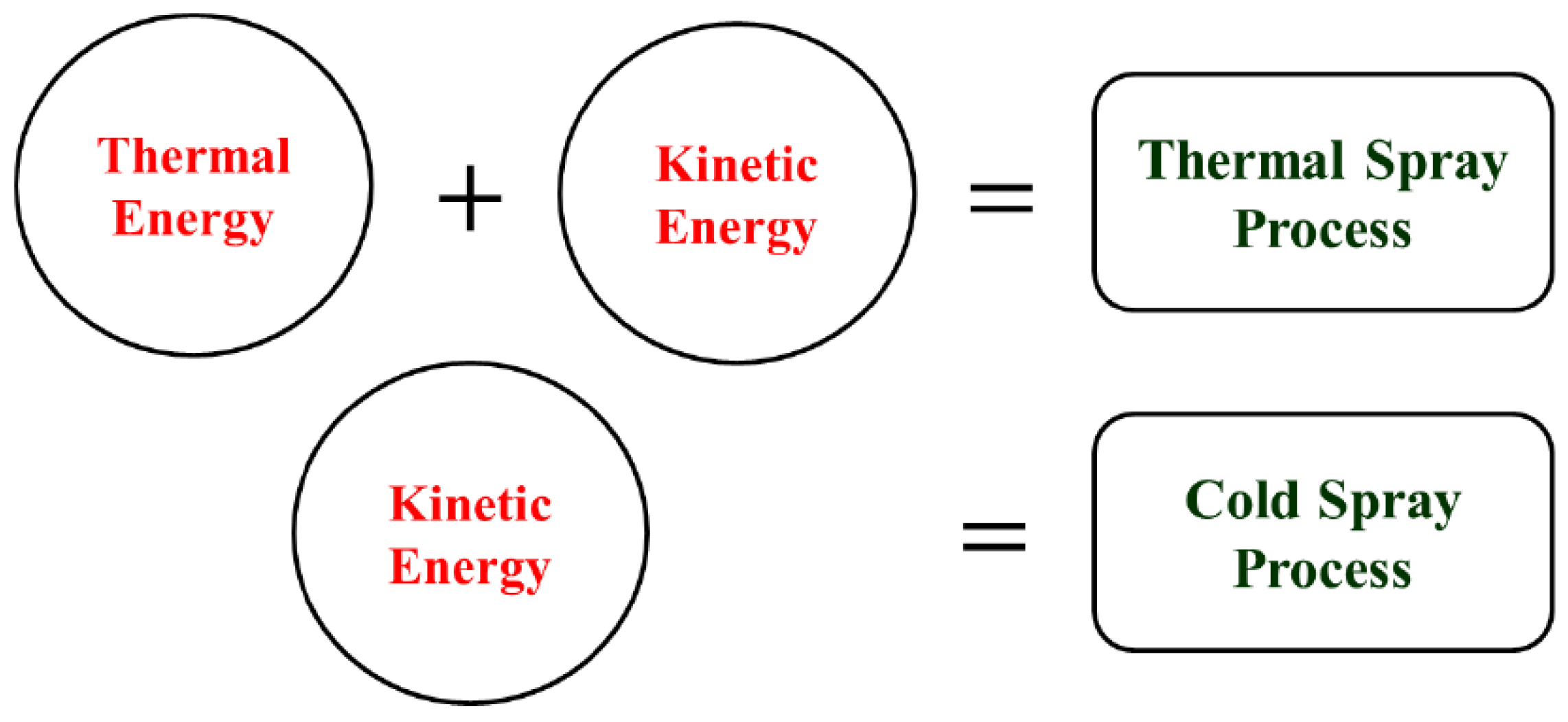
Figure 2.
Schematic diagram of a cold spray gun.
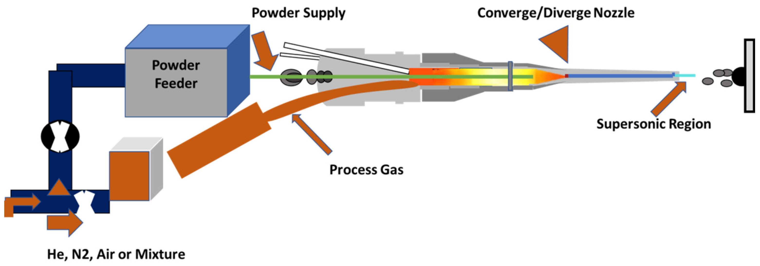
Figure 3.
Cold spray gun: (a) schematic; (b) photograph; (c) deLaval nozzle design [courtesy: Impact Innovations].
Figure 3.
Cold spray gun: (a) schematic; (b) photograph; (c) deLaval nozzle design [courtesy: Impact Innovations].

Figure 4.
Impact of a Cu particle on Cu substrate at successive times: (a) 5 ns; (b) 20 ns; (c) 35 ns; (d) 50 ns [32]. Copyright 2003 Elsevier.
Figure 4.
Impact of a Cu particle on Cu substrate at successive times: (a) 5 ns; (b) 20 ns; (c) 35 ns; (d) 50 ns [32]. Copyright 2003 Elsevier.

Figure 5.
Schematic of interfacial plastic deformation resulting in cold welding. Under high strain, there is contact between fresh metallic surfaces, grain boundaries form between the metals [28]. Copyright 2016 Elsevier.
Figure 5.
Schematic of interfacial plastic deformation resulting in cold welding. Under high strain, there is contact between fresh metallic surfaces, grain boundaries form between the metals [28]. Copyright 2016 Elsevier.

Figure 6.
Energy dispersive spectroscopy image of a copper particle on an aluminum substrate [31]. Copyright 2005 Springer.
Figure 6.
Energy dispersive spectroscopy image of a copper particle on an aluminum substrate [31]. Copyright 2005 Springer.
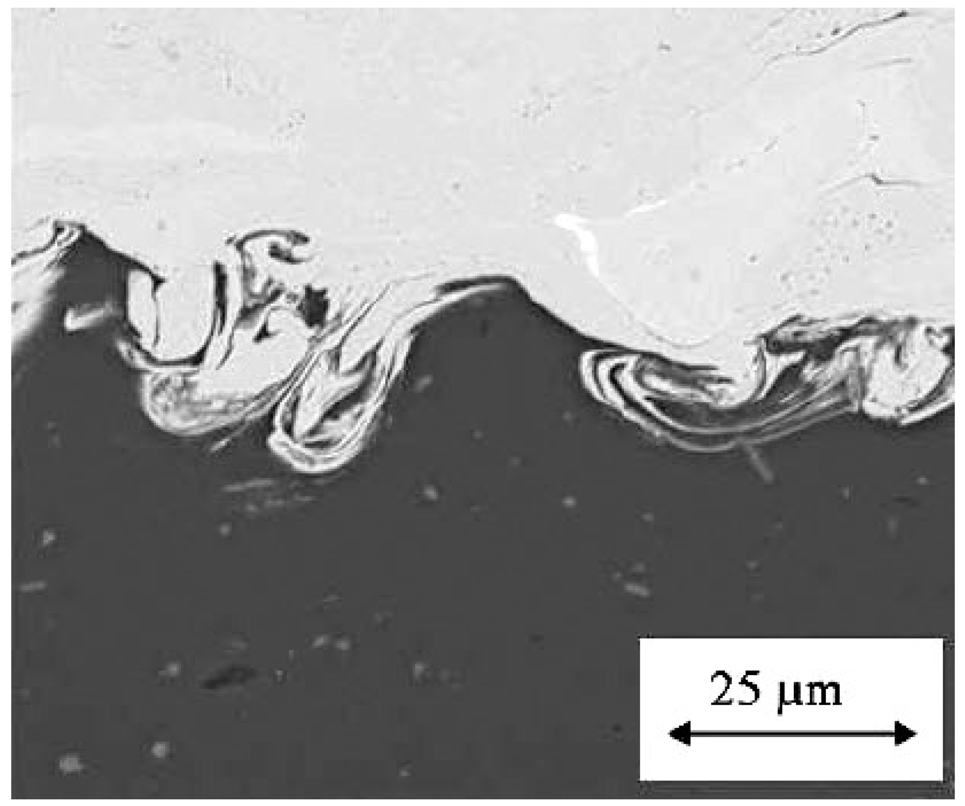
Figure 7.
Induction time (deposition delay) vs. mean particle velocity of aluminum particle on polished Cu substrate [31].
Figure 7.
Induction time (deposition delay) vs. mean particle velocity of aluminum particle on polished Cu substrate [31].
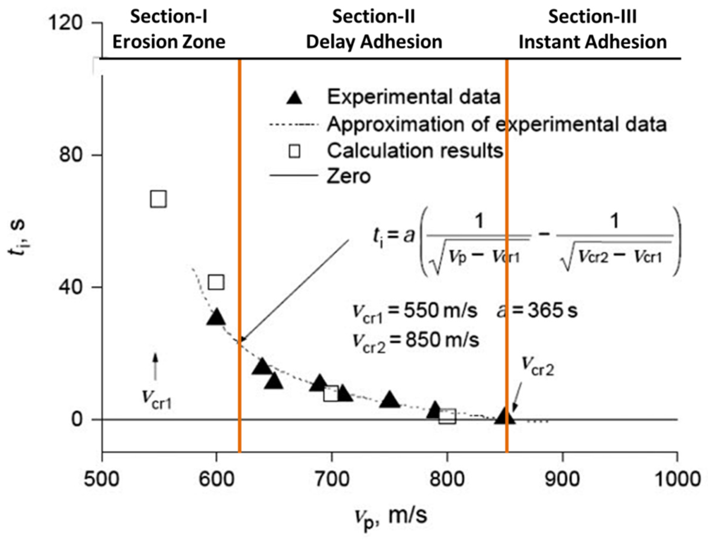
Figure 8.
Decomposition of particle impact velocity at spray angle θ [41].
Figure 8.
Decomposition of particle impact velocity at spray angle θ [41].
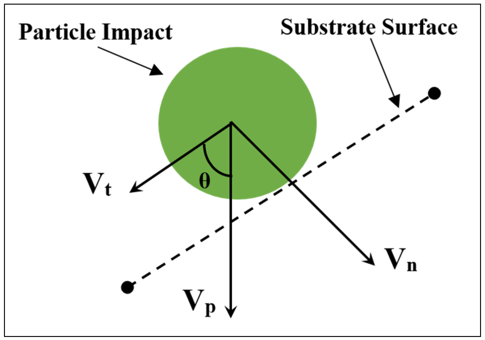
Figure 9.
Effect of spray angle on deposition efficiency: (a) copper (15–37 µm) and (b) titanium (37–44 µm) [41].
Figure 9.
Effect of spray angle on deposition efficiency: (a) copper (15–37 µm) and (b) titanium (37–44 µm) [41].
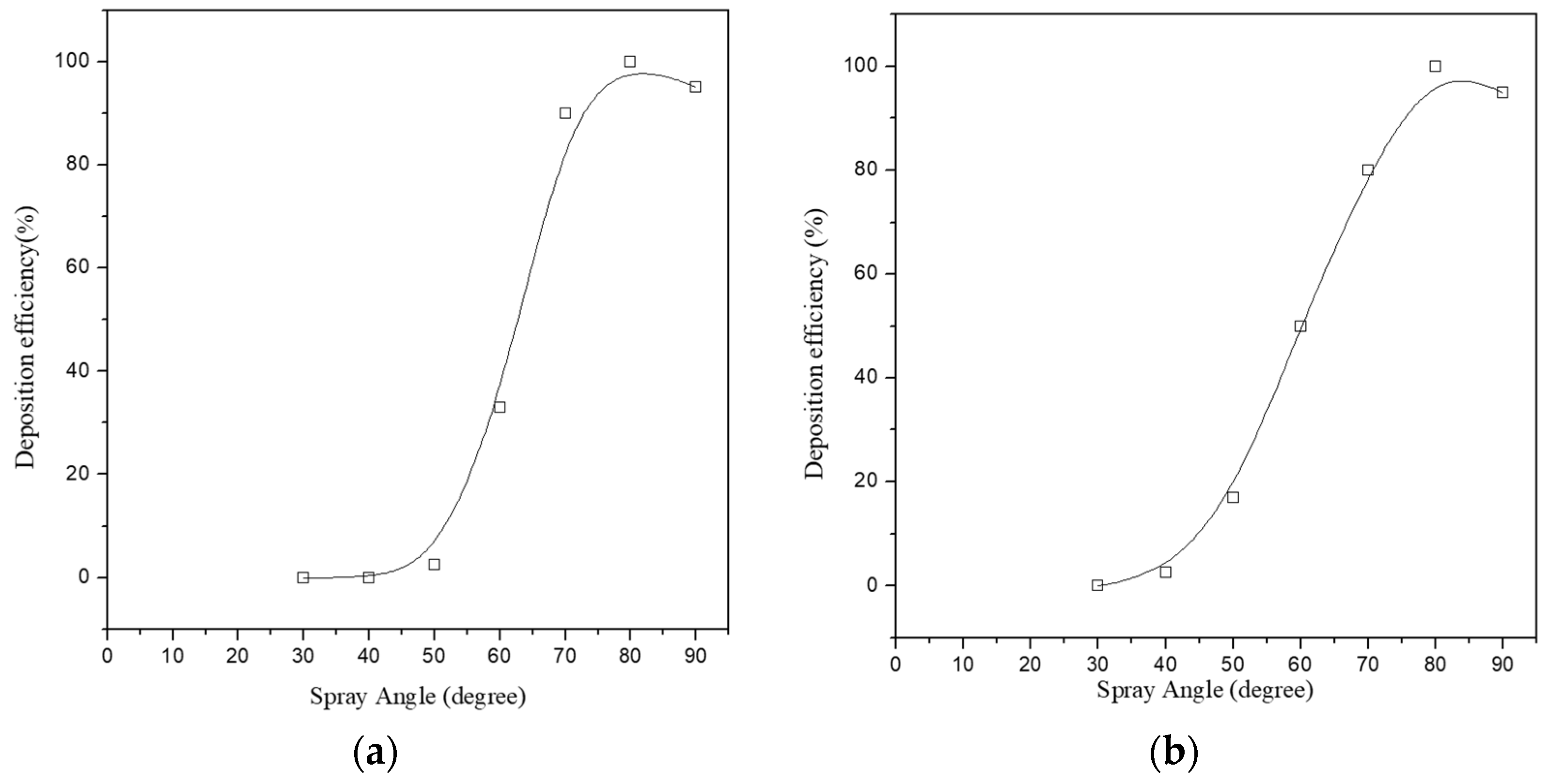
Figure 10.
Effect of spray angles on bonded particles and their corresponding deformation [43]. Copyright 2015 Springer.
Figure 10.
Effect of spray angles on bonded particles and their corresponding deformation [43]. Copyright 2015 Springer.
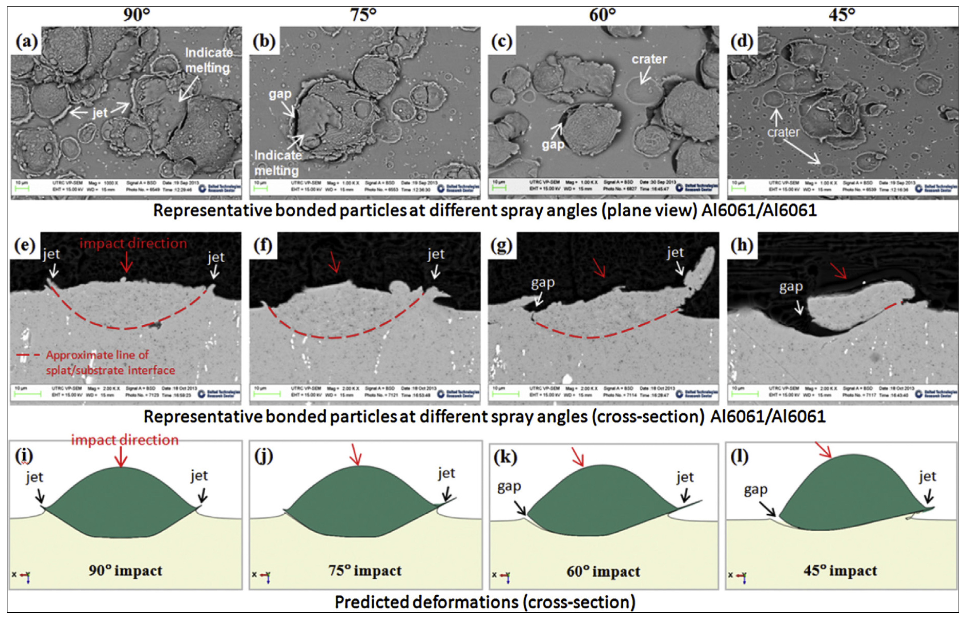
Figure 11.
Scanning electron microscopy (SEM) micrographs of cold sprayed Al deposit on as-sprayed (a) cross plane and (b) normal plane [41]. Copyright 2006 Elsevier.
Figure 11.
Scanning electron microscopy (SEM) micrographs of cold sprayed Al deposit on as-sprayed (a) cross plane and (b) normal plane [41]. Copyright 2006 Elsevier.
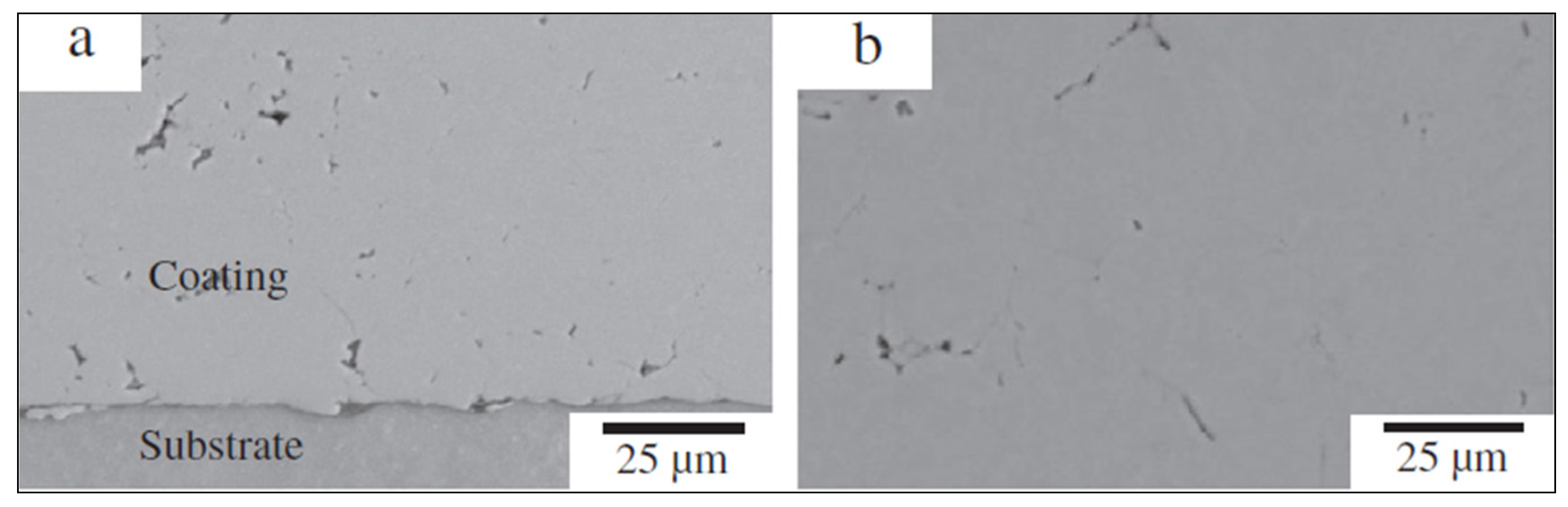
Figure 12.
SEM micrographs of deposited (a) Stellite 6, (b) Stellite 31 and (c) Stellite 31 + 10% AISI 316L coatings observed in cross-section [48]. Copyright 2015 Elsevier.
Figure 12.
SEM micrographs of deposited (a) Stellite 6, (b) Stellite 31 and (c) Stellite 31 + 10% AISI 316L coatings observed in cross-section [48]. Copyright 2015 Elsevier.

Figure 13.
SEM micrograph of high-energy mechanically-alloyed Al2O3-Ni(Cr) nanostructured cermet particles for high pressure cold spray coatings development [57].
Figure 13.
SEM micrograph of high-energy mechanically-alloyed Al2O3-Ni(Cr) nanostructured cermet particles for high pressure cold spray coatings development [57].
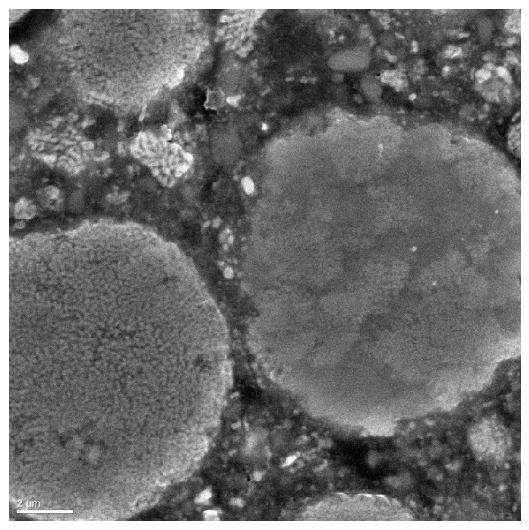
Figure 14.
SEM images of (a) W/Cu composite particle, and (b) cross-section of resulting high pressure cold spray coating [55]. Copyright 2003 Elsevier.
Figure 14.
SEM images of (a) W/Cu composite particle, and (b) cross-section of resulting high pressure cold spray coating [55]. Copyright 2003 Elsevier.

Figure 15.
Key features of cold spray as additive manufacturing.
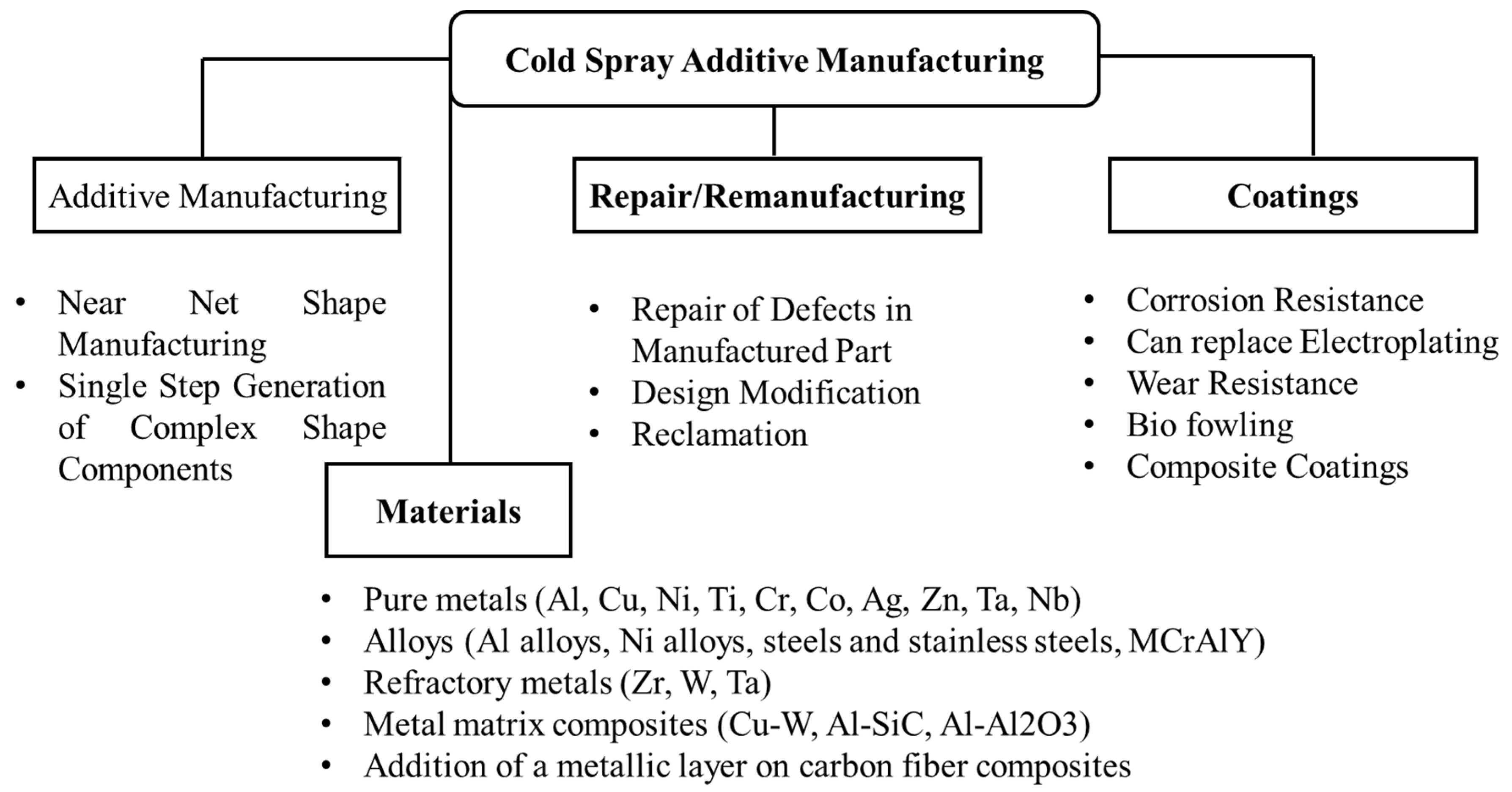
Figure 16.
Micrographs of (a) a hollow cylinder with end cap produced by cold spray; (b) a bracket produced by cold spray [60].
Figure 16.
Micrographs of (a) a hollow cylinder with end cap produced by cold spray; (b) a bracket produced by cold spray [60].

Figure 17.
(a) Multilayer Ti-Cu object and (b) its cut fragment fabricated by convenient cold spray system. Surface of part was machined by turning after cold spray deposition [62].
Figure 17.
(a) Multilayer Ti-Cu object and (b) its cut fragment fabricated by convenient cold spray system. Surface of part was machined by turning after cold spray deposition [62].
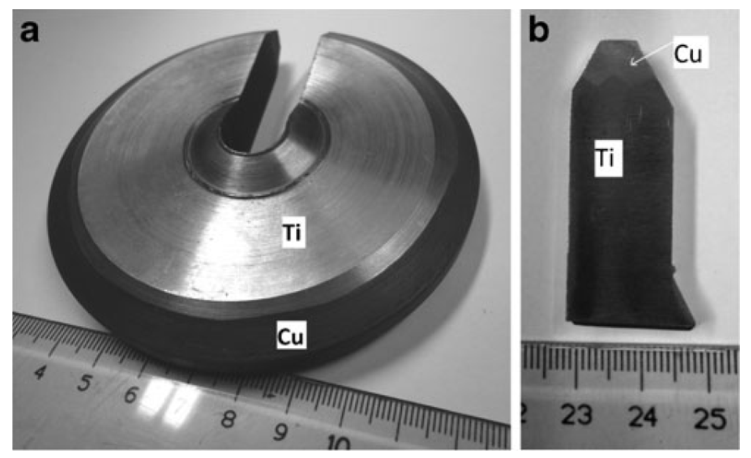
Figure 18.
Additional feature added to a machine component by cold spray additive manufacturing: (a) before spraying; (b) after cold spray; (c) finished [62].
Figure 18.
Additional feature added to a machine component by cold spray additive manufacturing: (a) before spraying; (b) after cold spray; (c) finished [62].
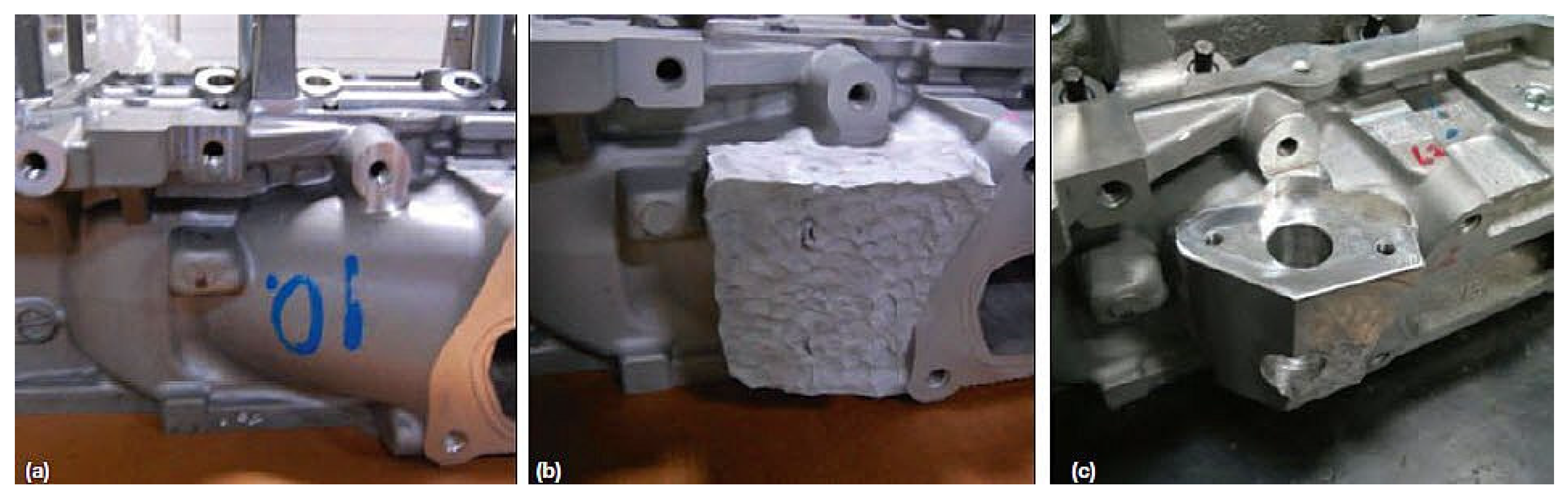
Figure 19.
(a) Damaged flap transmission tee box housing; (b) cold spray coating applied; (c) machined after cold sprayed [62].
Figure 19.
(a) Damaged flap transmission tee box housing; (b) cold spray coating applied; (c) machined after cold sprayed [62].
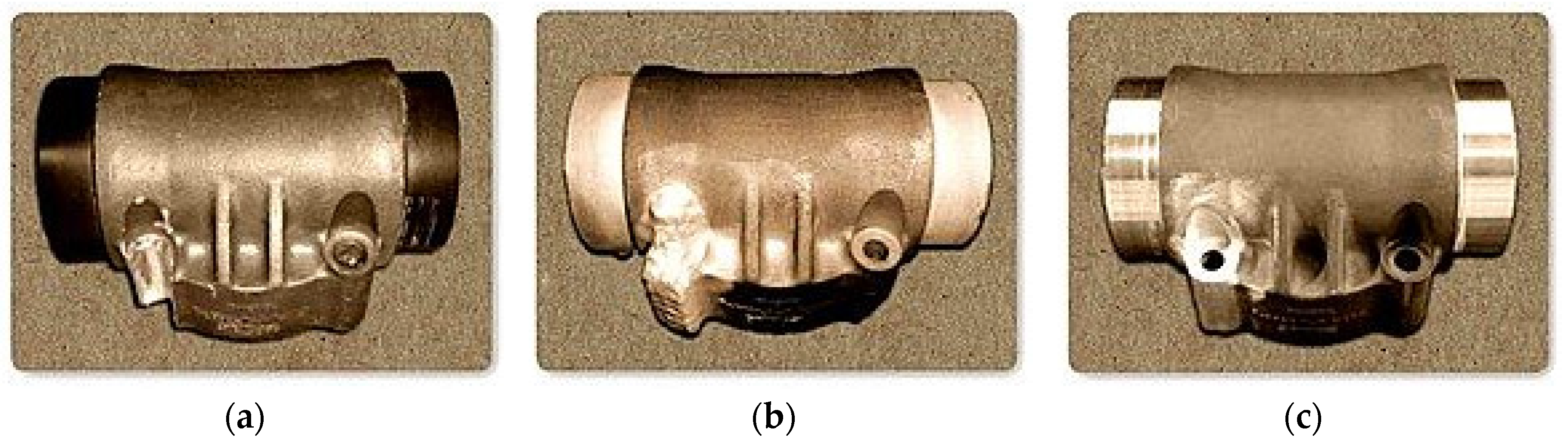
Figure 20.
Photographs of (a) defected Boeing nose wheel steering actuator and (b) cold spray nickel repaired 737 nose wheel steering actuator [62].
Figure 20.
Photographs of (a) defected Boeing nose wheel steering actuator and (b) cold spray nickel repaired 737 nose wheel steering actuator [62].
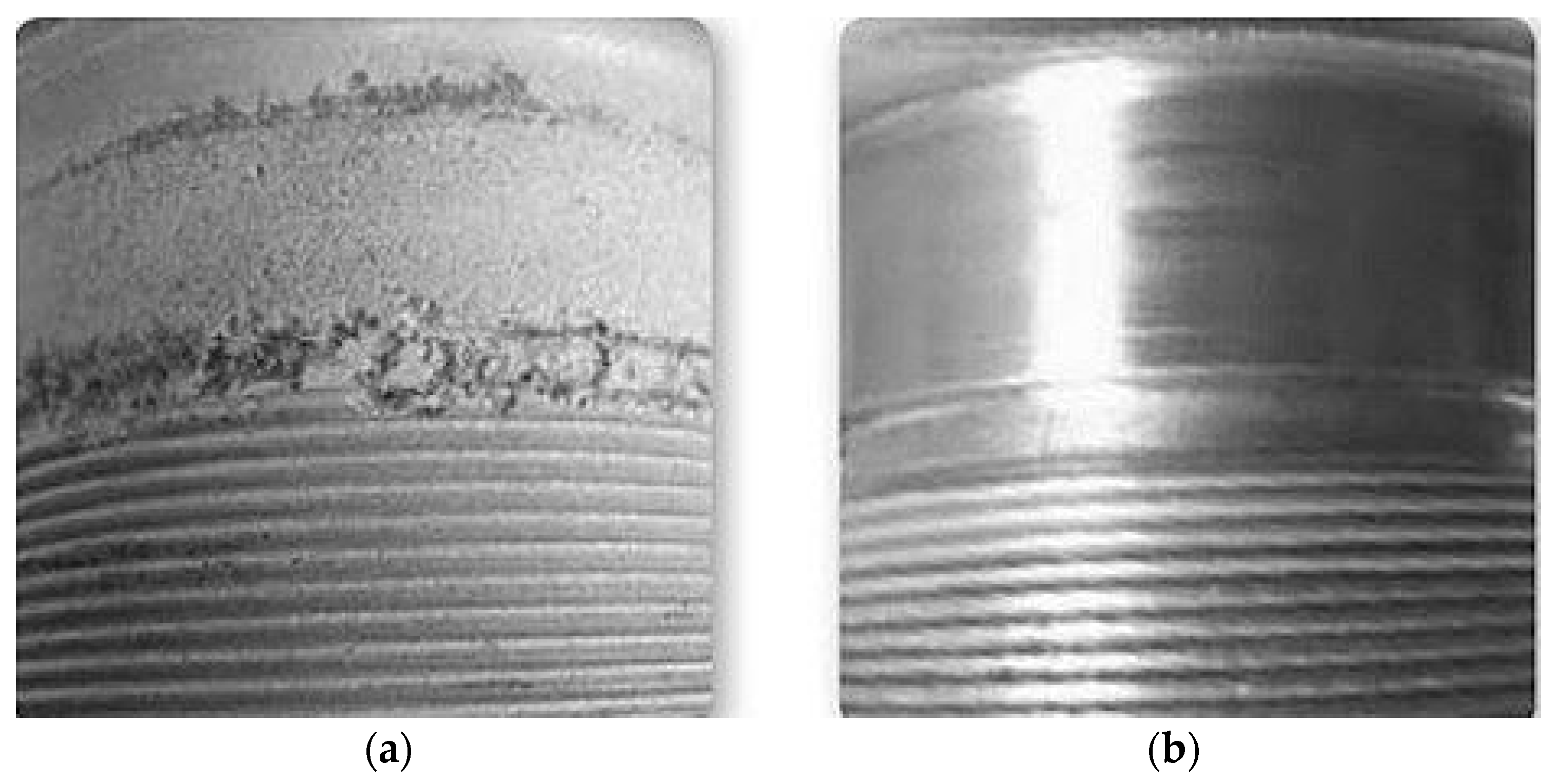
Figure 21.
Dimensional restoration of an iron engine block mount [63].
Figure 21.
Dimensional restoration of an iron engine block mount [63].
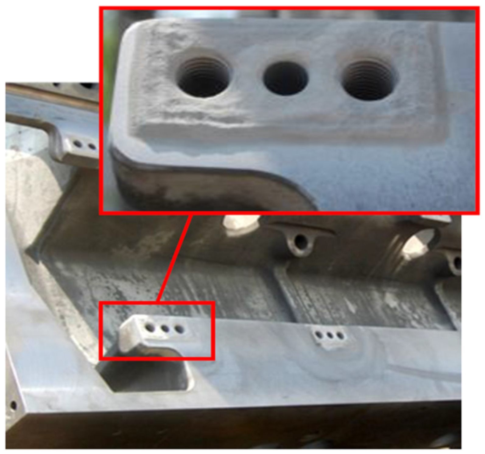
Figure 22.
Photographs of (a) comparsion of Cu embedded and with Cu-embedded in streamer skin; (b) Cu coating on polyurethane; (c) Cu embedded on cables; (d) Cu embedded on the net for fish farms [66,67,68].

Figure 23.
Schematic of (a) cold sprayed 6061 Al to the edge of the ZE41A Mg (buttering the edge) and (b) use of friction stir welding (FSW) to join the ZE41A Mg to 6061 Al [70].
Figure 23.
Schematic of (a) cold sprayed 6061 Al to the edge of the ZE41A Mg (buttering the edge) and (b) use of friction stir welding (FSW) to join the ZE41A Mg to 6061 Al [70].
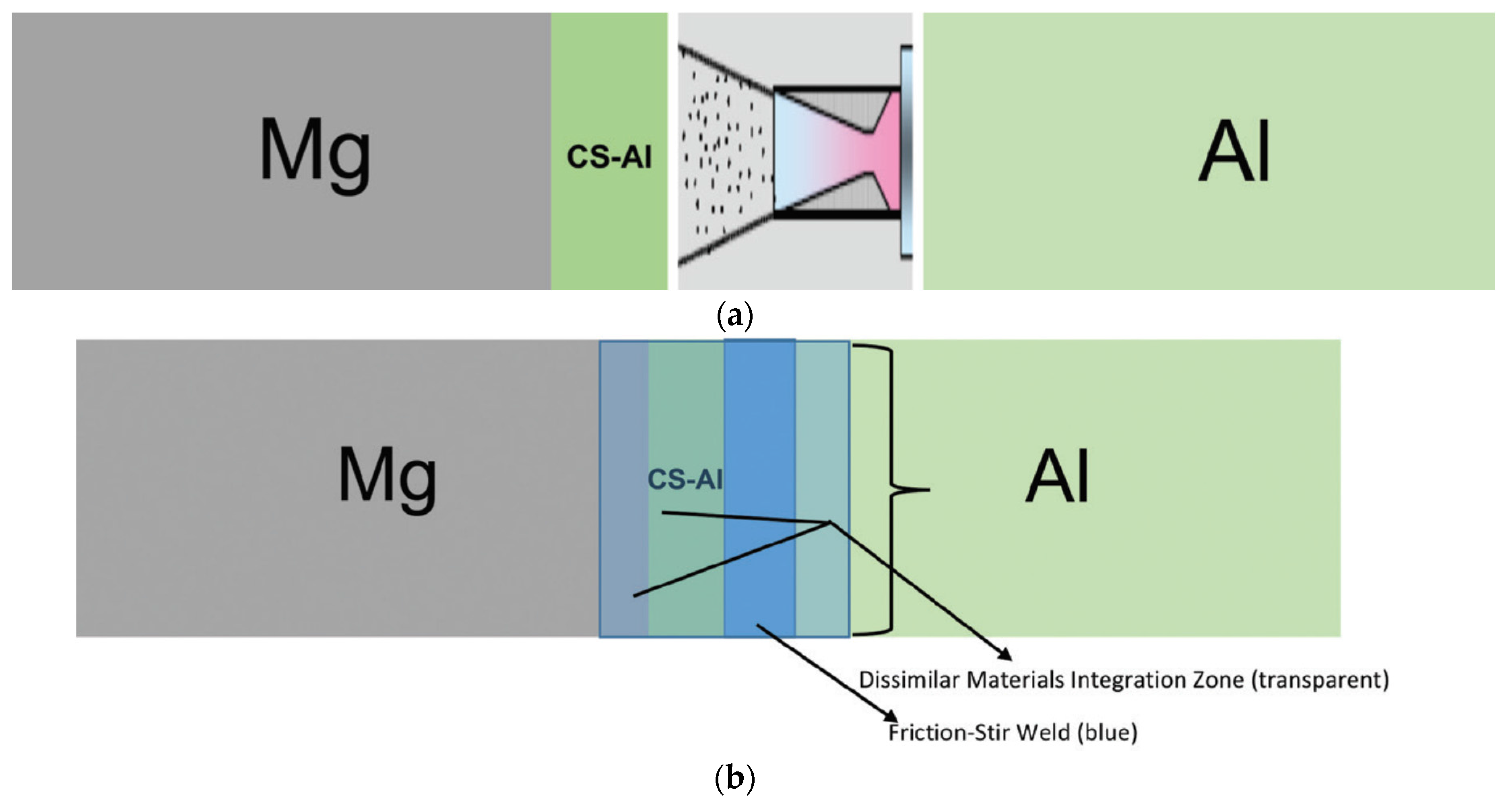
Figure 24.
Photograph of the ZE41A-T5 cast Mg, the cold spray Al transition layer, the friction stir weld, and the 6061-T6 wrought aluminum [62].
Figure 24.
Photograph of the ZE41A-T5 cast Mg, the cold spray Al transition layer, the friction stir weld, and the 6061-T6 wrought aluminum [62].


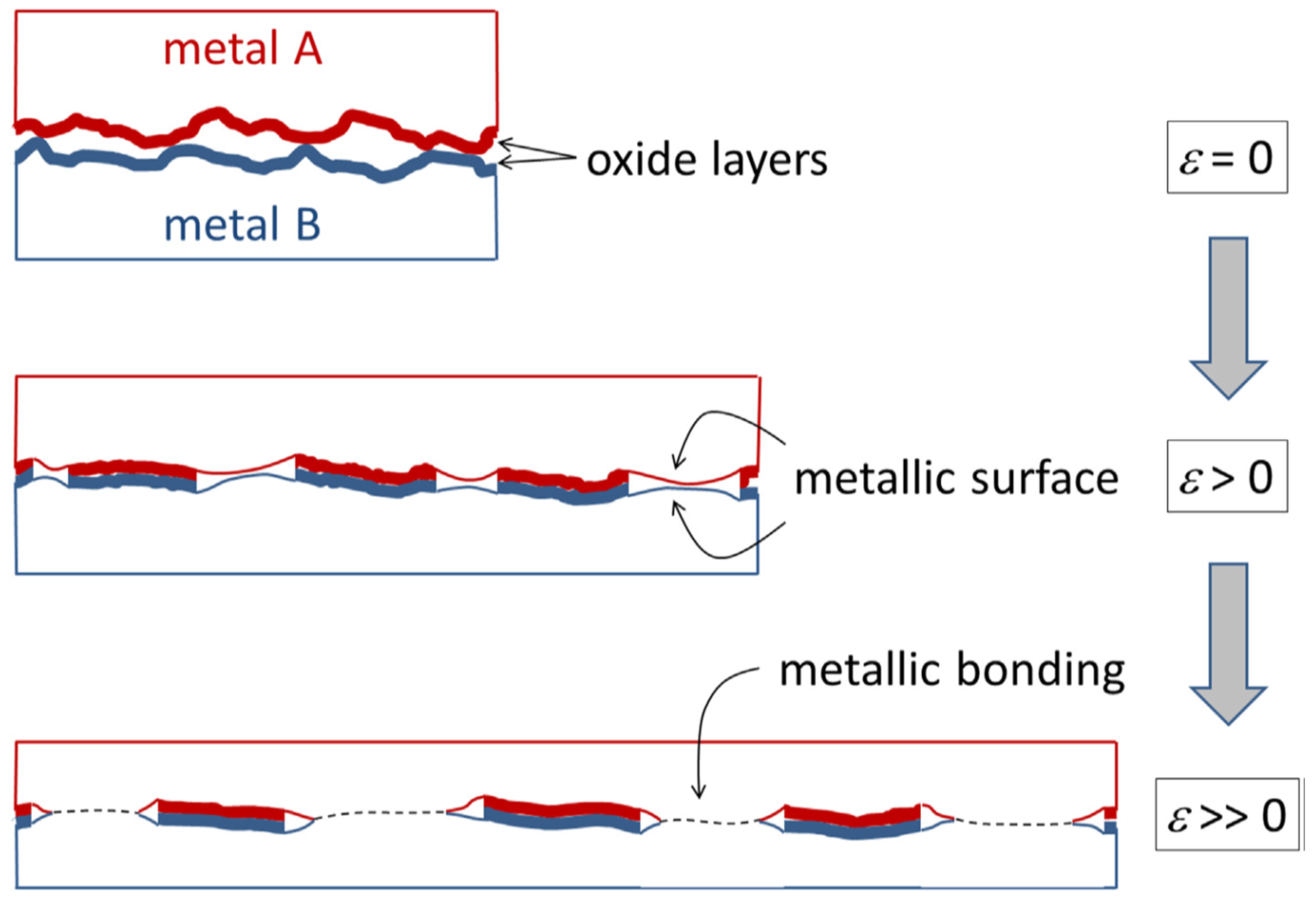
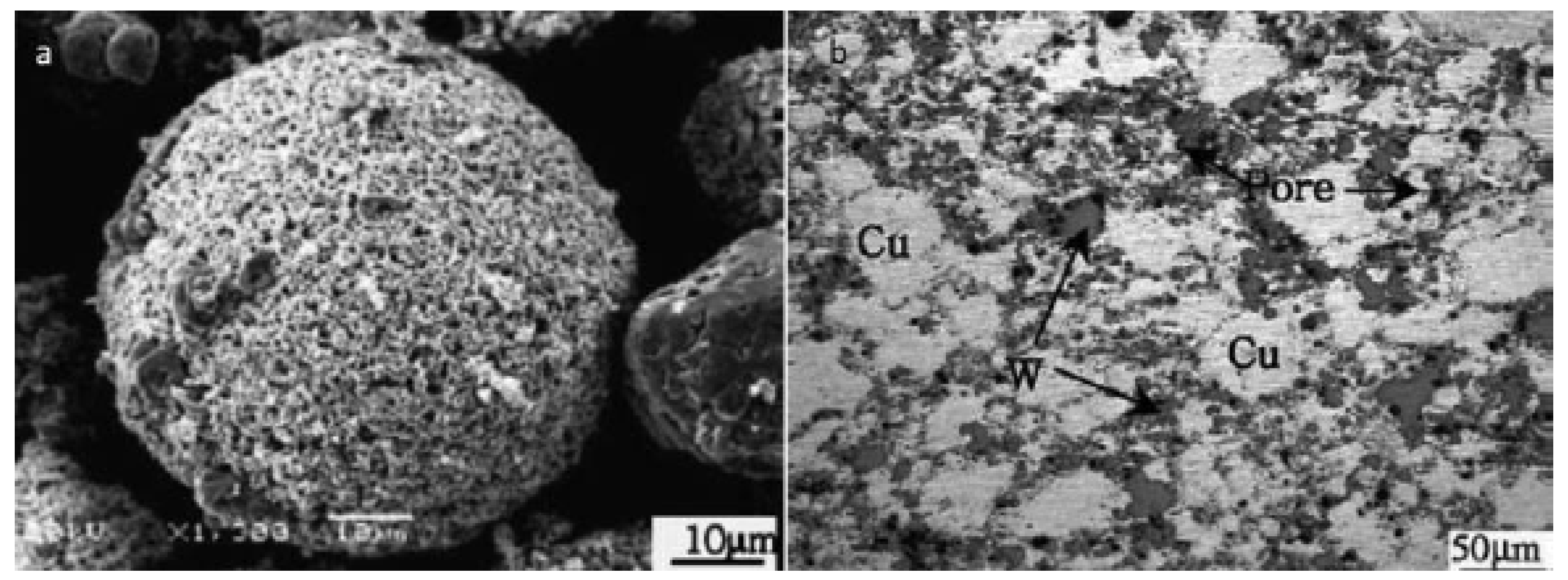
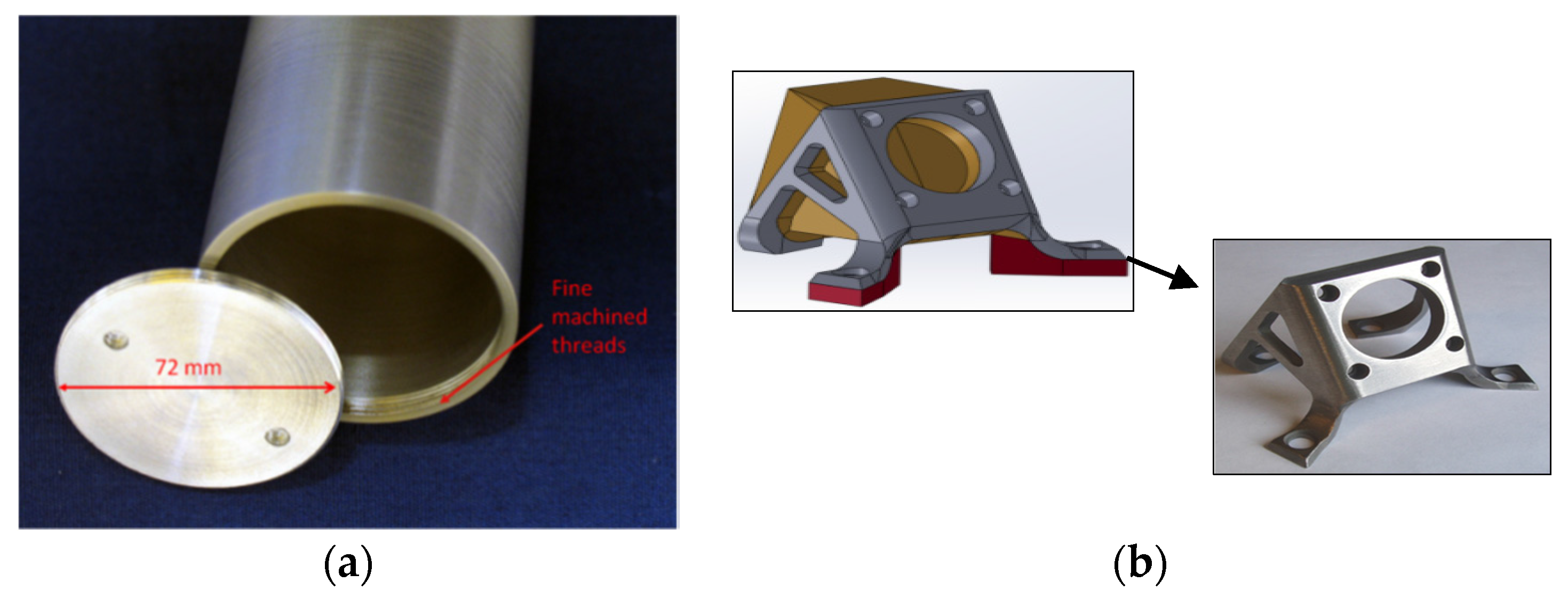
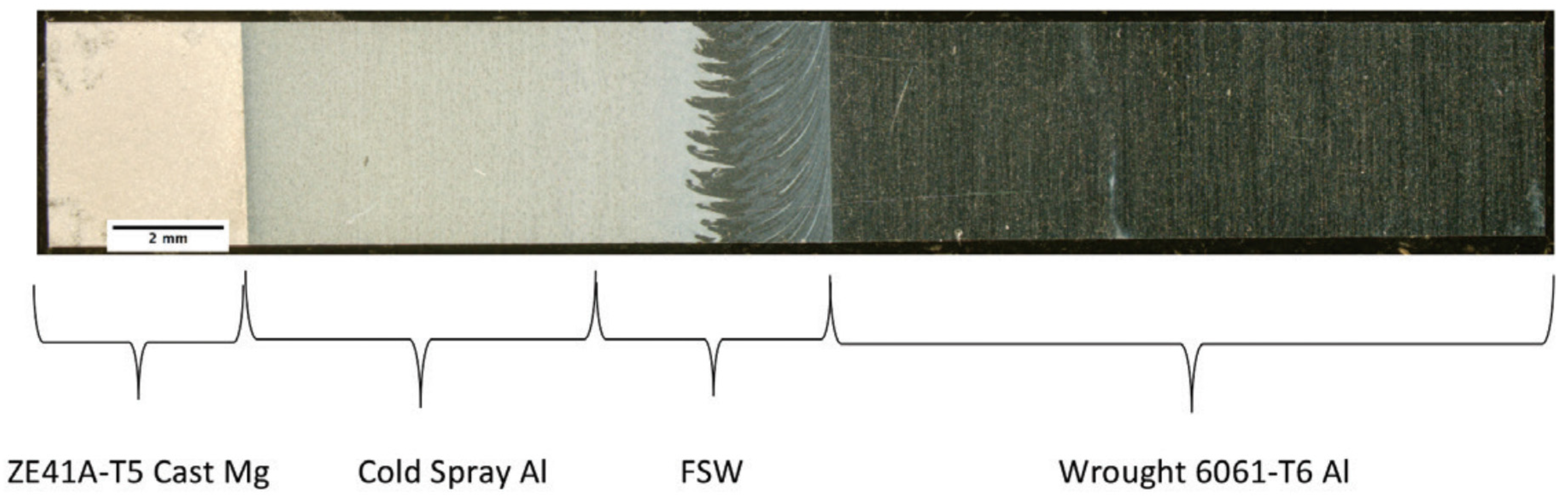
Table 1.
Applications and properties of cold spray coating materials [9,10,11,12,13,14,15,16,17,18,19,20,21,22,23,24,25].
| Coating Materials | Primary Property Benefits | Applications |
|---|---|---|
| Ceramic coatings (glass, cement linings) | Improved corrosion resistance and wear resistance | Furnace components, heat treating equipment, chemical processing equipment, heat exchangers, rocket motor nozzles, exhaust manifolds, jet engine parts, and nuclear power plant components etc. |
| Hard chromium coatings | Improved wear resistances, heat abrasion, and high corrosion resistance | Hydraulic pistons and cylinders, piston rings; aircraft engine parts, and plastic molds etc. |
| Zinc-aluminum alloys | Sacrificial galvanic protection for corrosion resistance, oxidation and sulfidation resistance | Bridges, ships, and other large structures power boilers and other high-temperature uses etc. |
| Cobalt based alloys | Improved wear resistances and high impact strength | Gate valves used in the offshore industry. Automotive engine, chemical processing & hydro-steam turbine industries etc. |
| Nickel based alloys | Good resistance to wear, oxidation and high temperature corrosion | Mill rolls, pumps, piston extruders and glass mold industry. Aerospace, automotive, medical devices, agriculture, wearing plates and pump bushing etc. |
| Iron based alloys | Improved wear resistances | Aero gas turbine, hydro or steam turbine, steel rolling mill, cement, chemical processing and textile industries etc. |
| Copper, silver, aluminum and titanium alloys | Excellent electrical conductivity or superior corrosion resistance | Applications that require excellent electrical conductivity or superior corrosion resistance are the two areas of greatest interest to motive and electronics etc. |
| Organic coatings (paints and polymeric or elastomeric coatings and linings) | Improved corrosion resistance, wear resistance, aesthetic appearance and excellent impact resistance | Aerospace, infrastructure, machine repair, agricultural harvesting components and oil drilling parts etc. |
© 2017 by the authors. Licensee MDPI, Basel, Switzerland. This article is an open access article distributed under the terms and conditions of the Creative Commons Attribution (CC BY) license (http://creativecommons.org/licenses/by/4.0/).
Share and Cite
MDPI and ACS Style
Pathak, S.; Saha, G.C. Development of Sustainable Cold Spray Coatings and 3D Additive Manufacturing Components for Repair/Manufacturing Applications: A Critical Review. Coatings 2017, 7, 122. https://doi.org/10.3390/coatings7080122
AMA Style
Pathak S, Saha GC. Development of Sustainable Cold Spray Coatings and 3D Additive Manufacturing Components for Repair/Manufacturing Applications: A Critical Review. Coatings. 2017; 7(8):122. https://doi.org/10.3390/coatings7080122
Chicago/Turabian StylePathak, Sunil, and Gobinda C. Saha. 2017. "Development of Sustainable Cold Spray Coatings and 3D Additive Manufacturing Components for Repair/Manufacturing Applications: A Critical Review" Coatings 7, no. 8: 122. https://doi.org/10.3390/coatings7080122
Note that from the first issue of 2016, this journal uses article numbers instead of page numbers. See further details here.