Article

Hydrogen Permeation, and Mechanical and Tribological Behavior, of CrNx Coatings Deposited at Various Bias Voltages on IN718 by Direct Current Reactive Sputtering

1
Department of General Physics, National Research Tomsk Polytechnic University, Tomsk 634050, Russia
2
Physical Metallurgy and Materials Technology, Brandenburg Technical University, 03046 Cottbus, Germany
3
Department of Linguistic, Potsdam University, 14469 Potsdam, Germany
4
Institute of Chemistry, Saint Petersburg State University, St. Petersburg 199034, Russia
*
Author to whom correspondence should be addressed.
Coatings 2018, 8(2), 66; https://doi.org/10.3390/coatings8020066
Submission received: 5 December 2017 / Revised: 30 January 2018 / Accepted: 4 February 2018 / Published: 9 February 2018

Abstract

:
In the current work, the microstructure, hydrogen permeability, and properties of chromium nitride (CrNx) thin films deposited on the Inconel 718 superalloy using direct current reactive sputtering are investigated. The influence of the substrate bias voltage on the crystal structure, mechanical, and tribological properties before and after hydrogen exposure was studied. It was found that increasing the substrate bias voltage leads to densification of the coating. X-ray diffraction (XRD) results reveal a change from mixed fcc-CrN + hcp-Cr2N to the approximately stoichiometric hcp-Cr2N phase with increasing substrate bias confirmed by wavelength-dispersive X-ray spectroscopy (WDS). The texture coefficients of (113), (110), and (111) planes vary significantly with increasing substrate bias voltage. The hydrogen permeability was measured by gas-phase hydrogenation. The CrN coating deposited at 60 V with mixed c-CrN and (113) textured hcp-Cr2N phases exhibits the lowest hydrogen absorption at 873 K. It is suggested that the crystal orientation is only one parameter influencing the permeation resistance of the CrNx coating together with the film structure, the presence of mixing phases, and the packing density of the structure. After hydrogenation, the hardness increased for all coatings, which could be related to the formation of a Cr2O3 oxide film on the surface, as well as the defect formation after hydrogen loading. Tribological tests reveal that hydrogenation leads to a decrease of the friction coefficient by up to 40%. The lowest value of 0.25 ± 0.02 was reached for the CrNx coating deposited at 60 V after hydrogenation.

1. Introduction

Nickel-based alloys are widely used in the aerospace industry due to their excellent corrosion resistance and good mechanical properties, even at elevated temperatures. IN718 is one of the most frequently used nickel-based alloys in aero-engine hot section components, aerospace structures, rocket components, and power generation turbines [1]. Despite its advantages, this alloy is susceptible to hydrogen embrittlement caused by the penetration of hydrogen resulting in degradation and catastrophic failure [2,3]. It is well-known that grain boundaries play an essential role in hydrogen-induced cracking and embrittlement in polycrystalline metallic materials [4,5,6,7,8,9,10,11]. It has been reported that at a high hydrogen concentration, the δ-phase in IN718 dramatically reduces the ductility of the alloy [12]. Furthermore, hydrogen embrittlement of IN718 occurs preferably at the grain boundaries even at low hydrogen concentration [13].
In order to reduce the sensitivity of the alloys against hydrogen embrittlement, different approaches were used. Hirose et al. [14] reported that laser surface softening leads to almost twice the higher ductility of the surface in comparison to the base materials. Heat treatment was used by Demetriou et al. [15] to decrease the hydrogen embrittlement. Furthermore, [16] describes that plasma immersion titanium implantation reduces the hydrogen absorption rate and total hydrogen concentration in the volume. Another opportunity is the development of hydrogen-resistant coatings on the IN718 alloy using magnetron sputtering. Chromium nitride coatings exhibit better corrosion- and oxidation-resistance in comparison to other nitride coatings [17,18,19]. Chromium nitride (CrNx) has attracted much attention in different tribological, material forming, and casting applications in terms of its high temperature stability, chemical inertness, high hardness, superior toughness, good wear resistance, and lower friction coefficient than TiN [19,20,21].
In our previous work the effect of hydrogenation on mechanical and tribological properties of Cr–N coatings deposited at different argon pressures was investigated with the result that a mixed cubic and hexagonal structure is preferential for hydrogen permeation-resistant coatings due to the presence of a cubic phase with high packing density [13]. Along with argon pressure, bias is one the most important parameters, which controls the deposition process [13,22]. A negative bias voltage applied to the substrate can influence nucleation and growth kinetics during coating growth, and will subsequently modify the microstructure and mechanical properties of the coatings [17,23,24,25,26,27,28]. Wan et al. [24] presented the evolution of the CrN phase structure with raising bias voltage with a maximum of hardness and residual stress for the coating deposited at approximately 100 V. Warcholinski et al. [18] measured the optimal hardness and elastic modulus for coatings deposited at 150 V, whereas the best adhesion occurred at low biases (10–70 V).
The aim of this paper is to investigate the influence of the bias voltage on the microstructure, mechanical, and tribological properties of the Cr-N coatings before and after high-temperature hydrogen exposure.

2. Materials and Methods

CrNx coatings were deposited using DC magnetron sputtering in a CC800/9 chamber from CemeCon AG (Würselen, Germany). The films were deposited onto Inconel 718 superalloy and (100) silicon wafers. Inconel 718 substrates were mirror polished, ultrasonically cleaned in acetone, and mounted into the chamber. The substrate-to-target distance of 70 mm was kept for all tests. A high purity single Cr target (99.99%) from CemeCon AG (Würselen, Germany) was used. For deposition of the coating with stationary table, the specimens were placed opposite to the target. A base pressure of less than 8.0 × 10⁻³ Pa was achieved inside the chamber before sputtering. Subsequently, the substrates were etched with Ar+ plasma at a bias voltage of −650 V for 30 min in order to remove surface contaminations and ensure good adhesion of the deposited films. The coating temperature was kept constant through all experiments at 773 K. In order to study the effect of the substrate bias voltage, different substrate bias voltages ranging from 60 to 120 V were applied while the pressure was kept constant at 600 mPa. The target power of 2 kW and N2/Ar ratio of 0.23 were kept constant during 30 min deposition process for all coatings, too.
The film thickness was measured using a CemeCon AG (Würselen, Germany) calowear test machine. The deposition rate was calculated from film thickness and corresponding deposition time. Cross-section images of the CrNx thin films deposited on Si wafers were analyzed by means of scanning electron microscopy (Mira II from Tescan, Brno, Czech Republic). The chemical composition of the CrNx layers was determined by wavelength-dispersive X-ray spectroscopy (WDS, Oxford Instruments, Wiesbaden, Germany).
Hydrogenation of the samples was performed using Gas Reaction Controller GRC LPB technique (Pittsburgh, PA, USA). The sample was inserted into the vacuum chamber, evacuated to the base pressure of 10 mPa and heated to 873 K with 6 K/min heating rate. Finally, the chamber was filled with hydrogen (99.999% purity) up to 0.203 MPa (2 atm.) pressure and kept for 2 h. After hydrogenation, the hydrogen was pumped out of the chamber during slow cooling. Elemental distribution was measured by high-frequency glow-discharge optical emission spectroscopy (GDOES) using a GD Profiler 2 (Horiba, Japan).
Crystallographic phases and XRD patterns of the coatings were identified using a Shimadzu XRD 7000S (Kyoto, Japan) equipped with OneSight wide-range high-speed detector at 40 kV and 30 mA with Cu Kα radiation (λ = 0.15406 nm). Hardness and elastic modulus values of the coatings were measured on a nanohardness tester NHT-S-AX-000Х from CSEM (Neuchatel, Switzerland). This device analyzes load changes and indenter penetration depth at the loading-unloading cycle using the Oliver and Pharr method [29]. A Berkovich indenter with an indenter load of 10 mN was used for all coatings. This load was chosen for the reason that the penetration depth of around 1/10th of the coating thickness was not exceeded [30]. The average of twenty measurements was reported. Friction coefficients were investigated using a high-temperature tribometer TNT-S-AH0000 from CSEM (Neuchatel, Switzerland) under dry friction conditions with vertical load of 5 N and a linear sliding speed of 2.5 cm/s for 15,000 laps (the travel length was approx. 150 m).

3. Results and Discussion

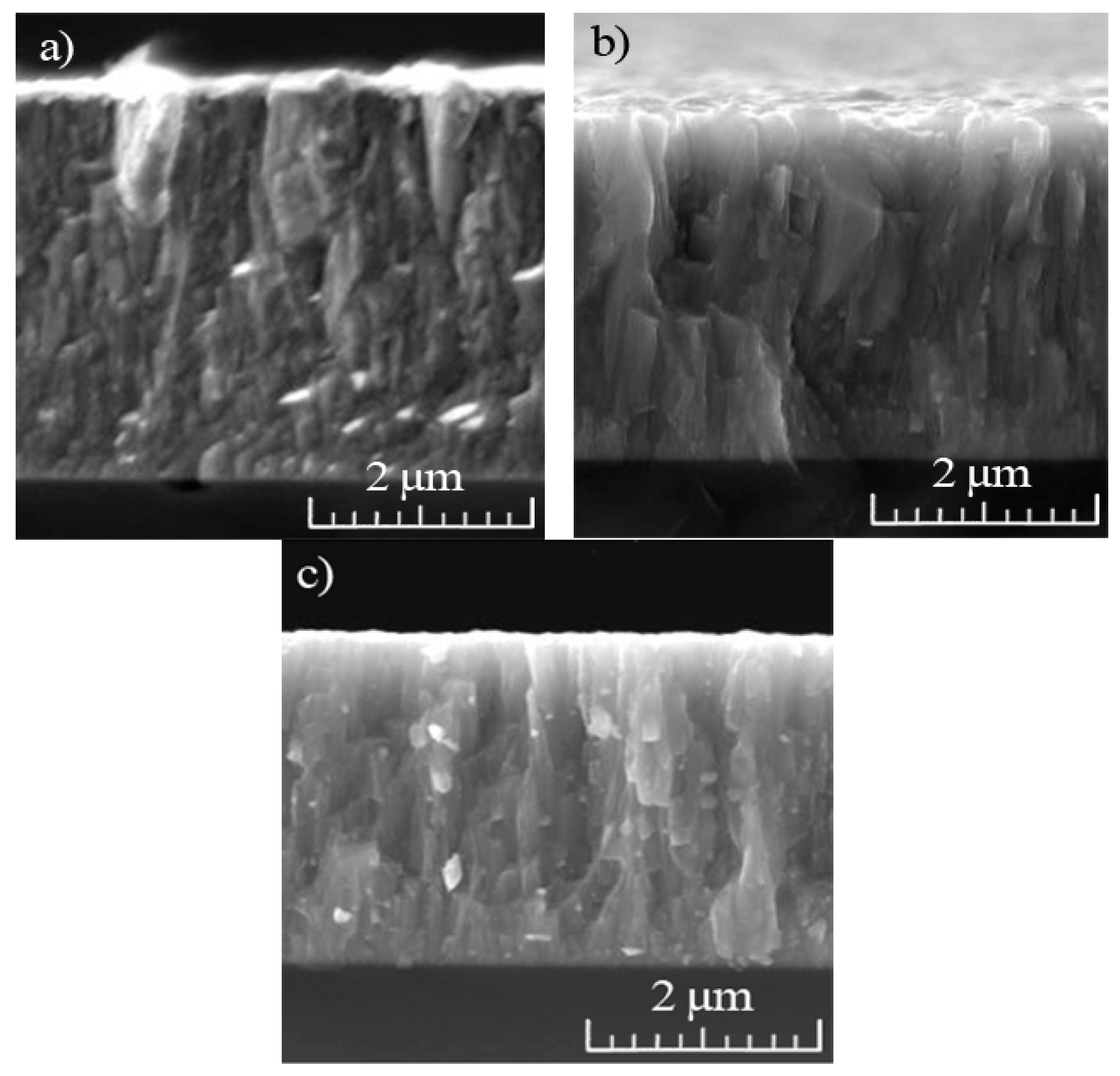
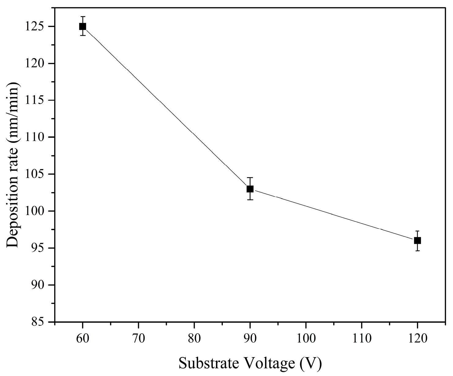
3.1. Morphology and Structural Analysis

The coating structure of CrNx-system at various substrate voltages is visible in Figure 1. The average column width decreases with increasing bias due to increasing high energy ion bombardment [31]. An almost structureless coating is obtained at higher bias, whereas a fibrous structure occurs at low substrate potentials. In case of CrNx coatings, the structure of the coating deposited at 60 V (Figure 1a) was much more porous than the one deposited at 120 V. Thus, increasing bias voltage leads to densification of the coating, confirming Messier’s structure zone model [31,32]. The denser structure can be explained by an increased ion mobility with rising substrate bias, resulting in the formation of more nucleation sites [18,33,34].
The chemical compositions of CrNx coatings deposited at different bias voltages are presented in Table 1. As the bias voltages increases from 60 V to 120 V, the Cr content increases from 58 at.% to 67 at.%, while the N content, correspondingly, decreases from 42 at.% to 33 at.%. The Cr/N ratio changes from 1.4 to 2.0, which corresponds to the transformation from mixed CrN + Cr2N to pure Cr2N [35,36]. The decrease in nitrogen content inside the film is a result of preferred re-sputtering of N as the lightest element within the condensed materials [23]. High substrate bias voltage favors the formation of Cr2N hexagonal phase, confirmed by Wang et al. [37].
The dependence of deposition rate on substrate bias during the sputtering process is plotted in Figure 2. The deposition rate continuously decreases with the increase in bias voltage from 125 nm·min−1 at 60 V to 95 nm·min−1 at 120 V. The film thickness reduction is related to sputtering off the film (re-sputtering) [38], too. With increasing bias voltage, the incident ion energy rises, and more atoms from the growing film will be re-sputtered. Heo et al. [39] reported a similar decrease in sputtering rate.

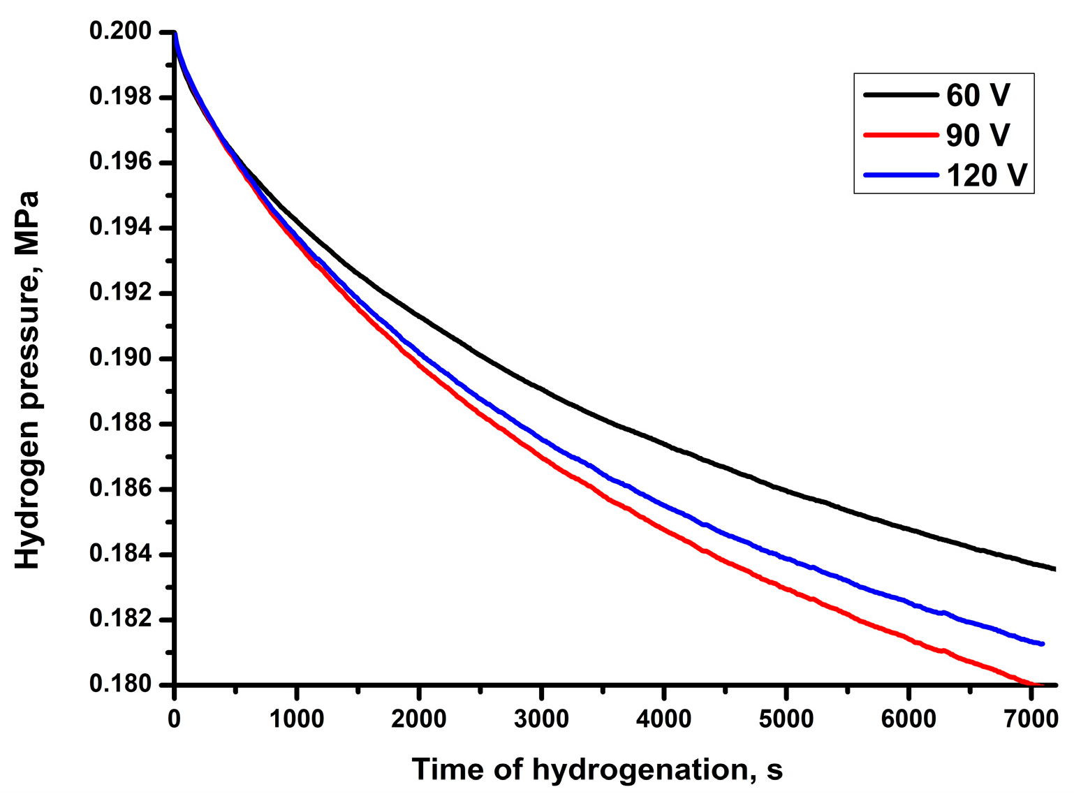
3.2. Gas-Phase Hydrogenation

Gas-phase hydrogenation was carried out to investigate hydrogen permeability across the deposited CrNx coatings, as well as the improvement of mechanical and tribological properties. The hydrogen absorption curves as function of hydrogen pressure in the chamber are shown in Figure 3. The slope of the curves describes the intensity of hydrogen absorption by the samples. The absorption curves are characterized by the gradual decrease of hydrogen pressure with tendency to hydrogen saturation.
The lowest hydrogen absorption was measured for the CrN coating deposited at 60 V, while the highest absorption rate was for the coating deposited at 120 V bias. The difference in hydrogen absorption is associated with the modification of crystalline structure and morphology of the coatings. On the one hand, the formation of mixed CrN + Cr2N phase in coatings deposited at 60 V leads to lower hydrogen permeation through the coating than the Cr2N phase formed at higher bias voltages [13,18,25]. On the other hand, the denser structure of the coatings deposited at higher bias voltages reduces the rate of hydrogen diffusion through the coating due to reduced intergranular space and pores in the coating. Thus, to reduce hydrogen permeation it is preferable to form a mixture of hexagonal Cr2N and cubic phase CrN inside the coating with a dense void-free structure.

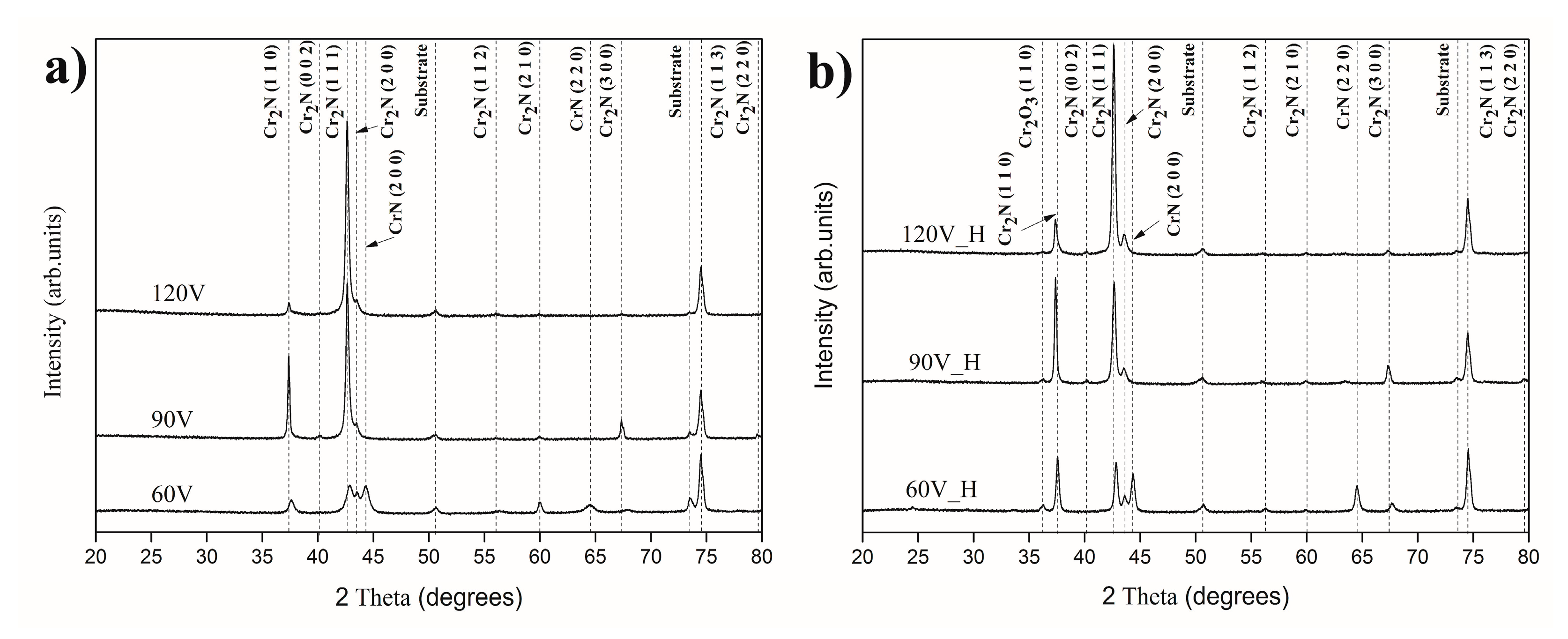
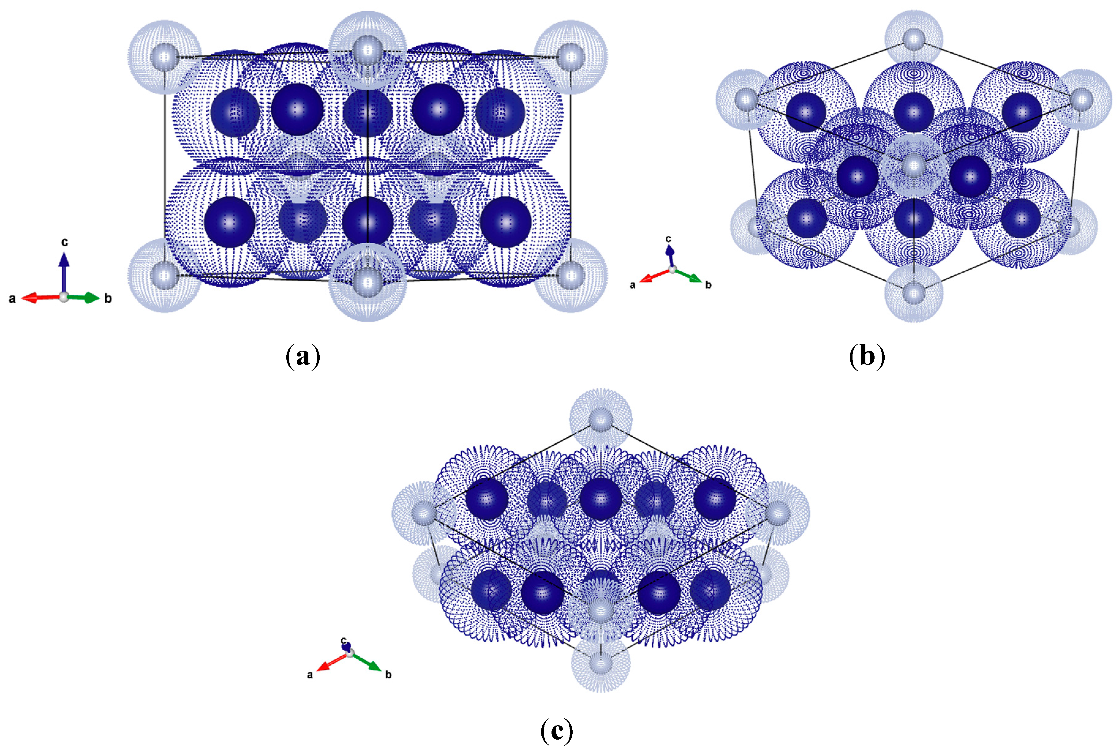
3.3. Crystalline Structure

According to the binary Cr–N phase diagram, three solid phases exist in the system: solid interstitial solution body centered cubic Cr(N), hexagonal Cr2N, and face-centered cubic CrN [35,40]. Figure 4a,b shows the XRD patterns of CrNx deposited at different substrate voltages before and after hydrogenation. Analysis of the X-ray diffraction patterns using the ICDD database revealed the presence of Cr2N (JCPDS 00-035-0803) and CrN (JCPDS 03-065-9001) phases. With increasing substrate bias, a change from mixed fcc-CrN + hcp-Cr2N to approximately stoichiometric hcp-Cr2N phase takes place (Figure 4a). Along with the strongest Cr2N (113) reflection, in the coating deposited at 60 V Cr2N (110), (111), (200), and CrN (200) reflections occur. In coatings deposited at 90 V bias, the CrN (200) reflection is disappeared, whereas the intensity of Cr2N (110) and (111) reflections increased, indicating a rotation in preferred orientation. The appearance of Cr2N (113) and (300) reflections could be related to the enhanced mobility of adatoms on the film surface at high deposition temperatures according to Shah et al. [41]. During further increase of the substrate bias, Cr2N (111) becomes the dominant reflection. Changes of bias voltages may also cause reflection shifting in the XRD spectra, and such a peak shift to lower 2θ values was observed for Cr2N (110) with increasing bias voltage, related to the chemical composition change [24,42].
After hydrogenation, the intensities of the peaks of CrN and Cr2N phases changed. Additionally, the (110) peak of Cr2O3 oxide phase was detected that probably was associated with the formation of the thin oxide layer on the surface during cooling of the sample after hydrogenation. Similar to our previous work, the lowest hydrogen absorption was found for the coating with mixed hcp-Cr2N and c-CrN phase composition due to the higher packing density of the cubic structure [13]. Zhou et al. [43] observed for titanium nitride coatings that hydrogen impermeability of the coating also depends on the crystal orientation of the films. In order to prove this supposition, the texture coefficients of Cr2N Tc(hkl) are calculated from their respective XRD peaks using the formula [44]:
T c ( h k l ) =   I   ( h k l ) / I 0 ( h k l ) 1 / N [ N I ( h k l ) / I 0 ( h k l ) ]
in which Tc(hkl) is the texture coefficient of the (110), (111), and (113) planes, respectively, I(hkl) is the measured intensity, I0(hkl) is the relative intensity of the corresponding plane given in PDF-4 data, and N is the number of reflections. The texture evolution of CrNx films deposited under various substrate bias voltages is depicted in Figure 5. The peak intensities and texture coefficients vary significantly with increasing substrate bias voltage. In the case of films deposited at 60V, predominantly (113) texture is developed. In films deposited at 90V, the mixture of (110) and (113) planes is present. At the highest bias voltage, all three texture components could be observed; however, (113) plane has the highest texture coefficient. After hydrogenation, all coatings reveal (113) and (110) texture, whereas the texture coefficient of (111) plane increases with increasing bias, but still remains less pronounced.
Hydrogen permeation depends on the crystal orientation within the films. As discussed above, CrN has a face centered cubic structure, whereas Cr2N is hexagonal. The shortest diffusion path to transport hydrogen through the coating is the cross section of the coating. In case of hexagonal structure, the (001) plane is the densest. Out of the planes measured in this work, the densest one is (110), followed by (111) and (113). In Figure 6, the crystal models of all three planes of Cr2N are presented. According to this, the coating with strong (110) texture should have the lowest hydrogen permeation. However, it could be suggested that crystal orientation is only one parameter influencing the permeation resistance of coatings together with film structure, presence of mixing phases, and packing density of the structure [13,43].

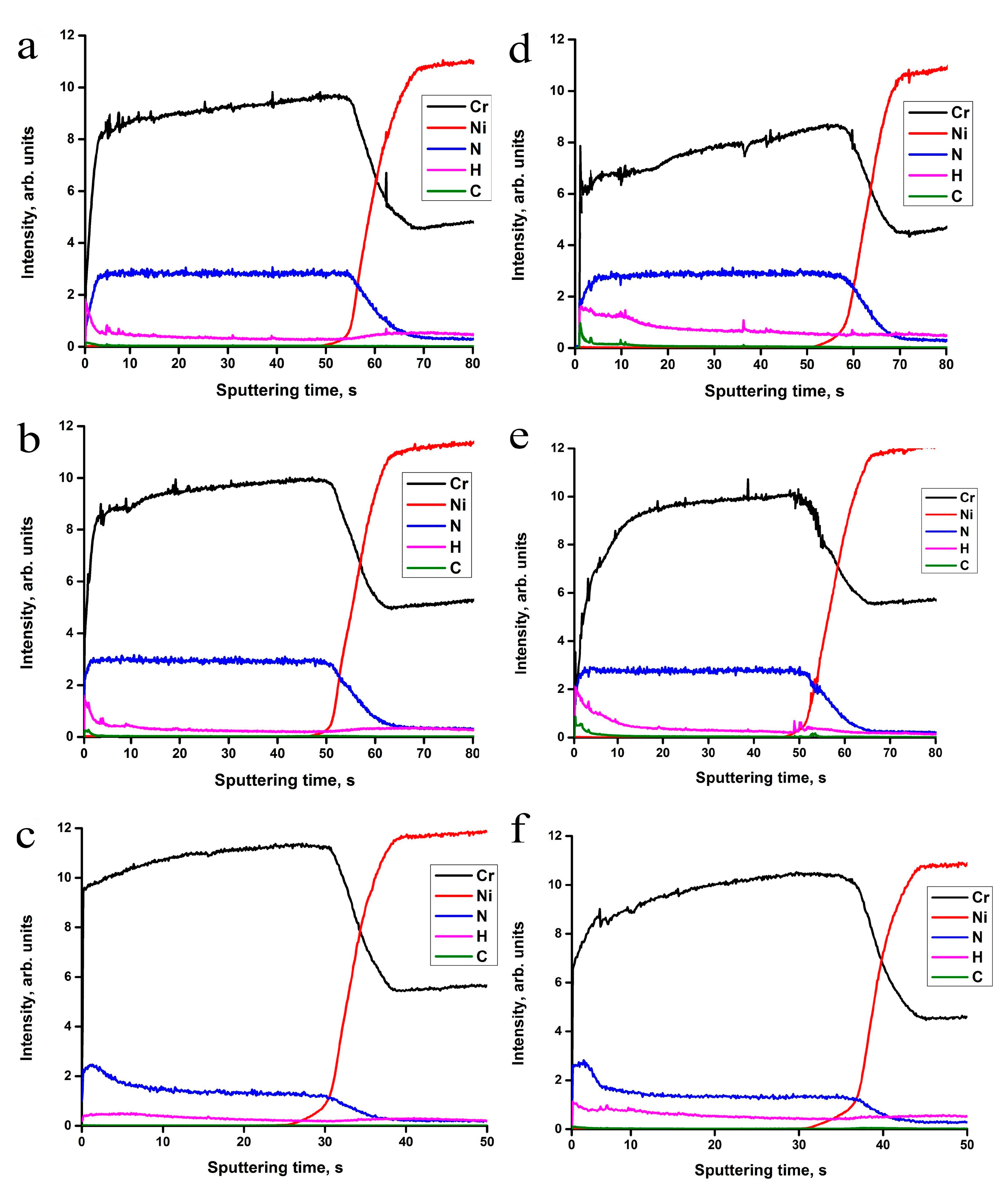
3.4. Depth Distribution of Elements

Figure 7 shows the depth distribution of elements in the samples before and after hydrogen exposure at 873 K and 0.203 MPa hydrogen pressure for 2 h. A uniform distribution of Cr and N elements is observed through the depth of the as-deposited CrNx coatings. Small fluctuations of signal intensities in the initial stage are associated with surface contaminations. The Cr to N ratio increases with increasing bias voltage, as evidenced by the changing of the ratio of Cr and N signal intensities, which is also confirmed by WDS measurements. The decrease in nitrogen concentration inside the coatings with increasing bias voltage could be attributed to the preferred re-sputtering of N as the lightest element in this combination [23]. The hydrogen concentration in the as-deposited coatings remains at the same level like hydrogen in the bulk IN718 alloy, which is typically few ppm.
Slight increase in hydrogen concentration inside the coatings was observed after hydrogenation (Figure 7d–f). During hydrogenation, hydrogen was absorbed by the samples, which was clearly related to the drop in pressure within the chamber (see Figure 3). Nevertheless, due to the degassing of hydrogen during slow cooling in vacuum, an insignificant amount of residual hydrogen remains inside the coating. In this case, hydrogen can stay in a dissolved form or be captured by defects. The hydrogen captured by structural defects cannot completely degas because of the strong binding energy of hydrogen in certain types of defects [45,46].

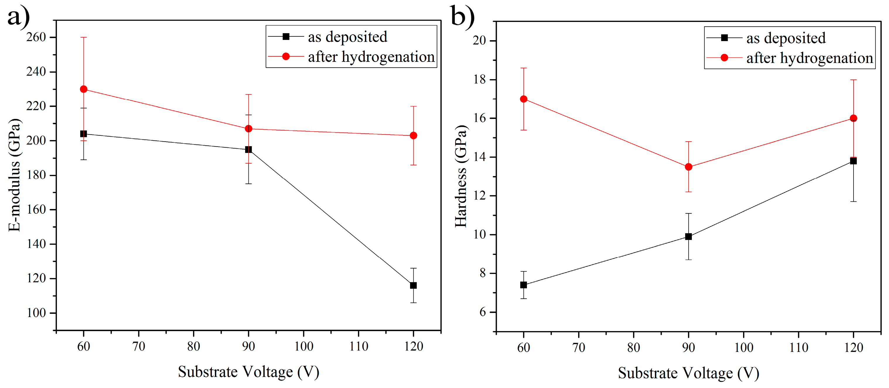
3.5. Mechanical Properties
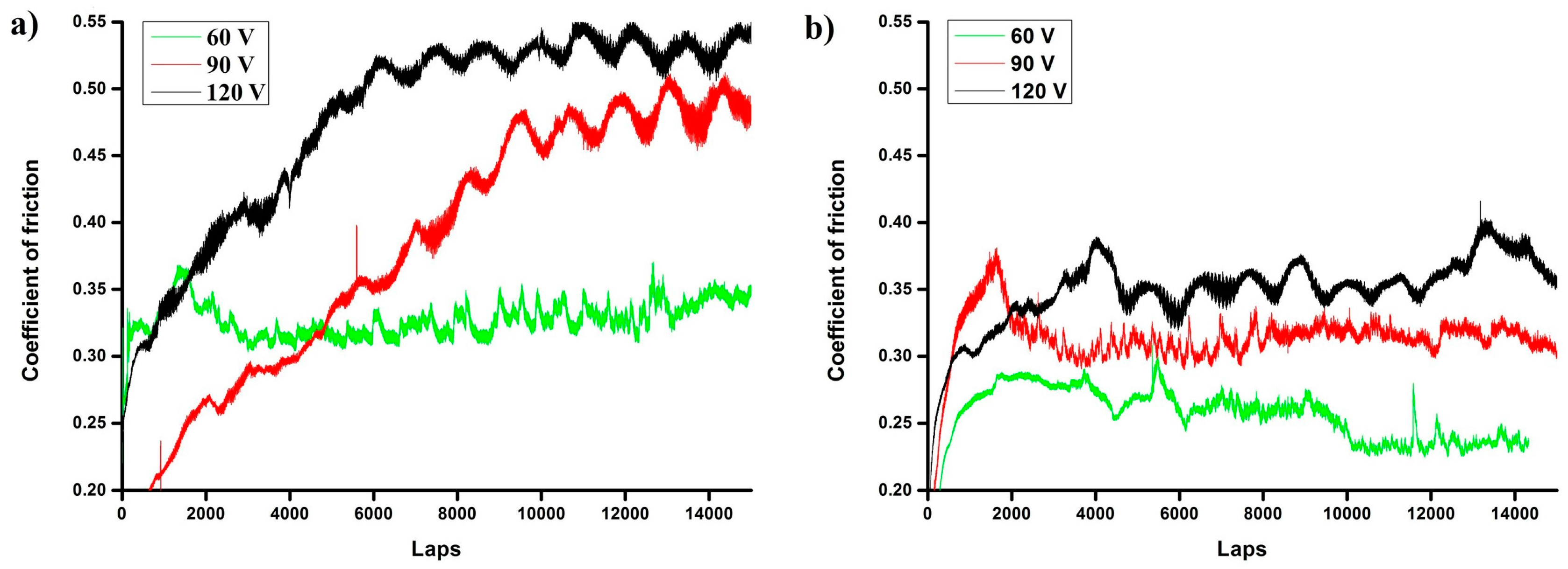
The evolutions of elastic modulus (E) and hardness (H) of the deposited coatings as function of the substrate voltage are shown in Figure 8. Hardness increases with increasing substrate bias, whereas the E-modulus drops from 205 GPa for the coating deposited at 60 V to 110 GPa for the one deposited at 120 V. Warcholinski et al. [18] presented similar changes in hardness. This change of mechanical properties can be correlated to the structure of the coatings. The fibrous columnar coating shows low hardness and high E-Modulus values, whereas the coating with dense structure depicts higher hardness and low E-Modulus values. Furthermore, phase composition plays an important role, because the Cr2N phase exhibits better mechanical properties (hardness and elastic modulus) due to higher covalent bonding character in Cr2N than the CrN phase [32,47]. Hardness evolution can be attributed to grain size, texture components, and the residual stress as well [42]. The low hardness of the deposited coatings could be attributed to (1) chromium phase precipitation at the grain boundaries of CrN and Cr2N phases causing increased grain boundary sliding, and (2) enhanced dislocation movement in the coating. The hardness of coatings is directly linked to its ability to deform under applied load by dislocation movement, grain boundary sliding, crack initiation, or similar mechanisms. Enhanced dislocation movement in the coating may cause reduced hardness, while deformation by dislocation movement requires less energy than by grain boundary sliding. The enhancement of the coating hardness could be caused by the grain refinement effect with increasing bias voltage [48].
Chu et al. [49] found that the residual stress was clearly related to the negative bias voltages, and high hardness is a result of such high residual stress. The compressive stress arises because of a process called “atomic peening”, in which some atoms squeeze into the lattices directly, causing internal stress and increasing the coating hardness [24,50]. However, further increase of the bias voltage can lead to reduced hardness, because the superfluous bombarding energies can cause lattice relaxation and recrystallization. Thus, the crystalline defects will be annihilated and the reduction of hardness is induced [24]. Lin et al. [51] presented the maximum of stress for bias voltages of about 100 V.
Typically, under high temperature coating, hardness reduction occurs. However, after hydrogenation, the hardness increased for all the coatings. Furthermore, the hardness of the coating deposited at 60 V increased more than twice up to 17 GPa. This change could be attributed to the formation of a Cr2O3 oxide film on the surface, whose hardness can reach up to 30 GPa [52]. Furthermore, the increased hardness can be associated with defect formation after hydrogen loading. The hydrogen solubility in thin films or coatings often exceeds the value for bulk systems, which is attributed to preferred hydrogen trapping at open volume defects (dislocations, grain boundaries, surfaces, and vacancies) [53]. With increasing hydrogen concentration inside the coating, the compressive stresses usually increase due to hydrogen incorporation into the open volume defects (solid solution hardening), hydrogen-induced vacancy formation, and creation of dislocations (strain hardening) observed in [54,55]. Similarly, first-principles calculations of Ti3SiC2 and Ti3AlC2 MAX-phases with hydrogen interstitial defects show that both phases are hardened after introduction of hydrogen [56].

3.6. Tribology

Figure 9 shows the evolution of the friction coefficient of as-deposited and hydrogen-exposed CrNx coatings. The friction behavior of as-deposited CrNx coatings depends on the applied bias voltage: the coefficient of friction (CoF) remains constant on a low level for the coating deposited at 60 V and rapidly increases for the coatings deposited at 90 and 120 V. In the initial stage, the strong fluctuations in the CoF are caused by ploughing friction arising from micro surface asperities [46]. The wear of the coating deposited at 60 V is characterized by a low debris effect, due to softer particles formed during the wear of the coating or the formation of oxides on the surface. The wear debris increases with increasing hardness of the coatings deposited at higher bias voltages, because the entrapped hard wear particles cause ploughing friction. Thus, fluctuations and rapid increase in the friction coefficient can be attributed to ploughing due to third-body hard particles. [57,58]. The CrNx coatings after hydrogenation show much lower (by 20–40%) friction coefficients than all initial samples. The best CoF value was 0.25 ± 0.02 for the hydrogen-exposed Cr-N coating deposited at 60 V bias. Similar changes in the friction coefficient were observed during sliding wear of as-deposited and at 773 and 873 K annealed CrN coatings against an Al2O3 ball [59]. This change was attributed to the lubrication effect of Cr–O oxides on the surface. In the current study, XRD results show the appearance of chromium oxide peaks after hydrogen exposure. Therefore, the decrease in CoF could be attributed to the oxides on the surface as well.

4. Conclusions

In the current study, the influence of the substrate bias voltage on mechanical and tribological properties of CrNx thin films grown on IN718 substrate by direct current reactive magnetron sputtering before and after hydrogenation was investigated. X-ray diffraction (XRD) results reveal a transformation from mixed fcc-CrN + hcp-Cr2N to, approximately, the stoichiometric hcp-Cr2N phase with an increasing substrate bias. The Cr/N ratio increases from 1.4 to 2.0 with increasing substrate bias from 60 to 120 V, respectively. The hydrogenation at 873 K of CrNx films deposited at 60 V with mixed c-CrN and (113) textured hcp-Cr2N phases presents better hydrogen impermeability than the coatings with hcp-Cr2N phases and mixed texture. Moreover, the denser microstructure formed under higher bias voltage also positively affects the resistance to hydrogen permeation. After hydrogenation, the hardness increased for all the coatings and the friction coefficient drops up to 40%. The lowest value of 0.25 ± 0.02 was reached for the CrNx coating deposited at 60 V after hydrogenation. It is suggested that crystal orientation is only one parameter influencing the hydrogen permeation resistance of CrNx coatings together with the film’s structure, the presence of mixed phases, and the packing density of the structure.

Acknowledgments

The authors are thankful to Sebastian Bolz for performing the WDS measurements. The research is funded from Tomsk Polytechnic University Competitiveness Enhancement Program grant.

Author Contributions

Aleksei Obrosov carried out the deposition process. Aleksei Obrosov and Egor B. Kashkarov analyzed the results and prepared the paper with a help of Elena Uludintceva and Andrei Mitrofanov. Alina N. Sutygina provided nanoindentation and described results. Sabine Weiß revised the manuscript.

Conflicts of Interest

The authors declare no conflict of interest.

References

  1. Iturbe, A.; Giraud, E.; Hormaetxe, E.; Garay, A.; Germain, G.; Ostolaza, K.; Arrazola, P.J. Mechanical characterization and modelling of Inconel 718 material behavior for machining process assessment. Mater. Sci. Eng. A 2017, 682, 441–453. [Google Scholar] [CrossRef]
  2. Jothi, S.; Merzlikin, S.V.; Croft, T.N.; Andersson, J.; Brown, S.G.R. An investigation of micro-mechanisms in hydrogen induced cracking in nickel-based superalloy 718. J. Alloy Compd. 2016, 664, 664–681. [Google Scholar] [CrossRef]
  3. Jothi, S.; Croft, T.N.; Wright, L.; Turnbull, A.; Brown, S.G.R. Multi-phase modelling of intergranular hydrogen segregation/trapping for hydrogen embrittlement. Int. J. Hydrogen Energy 2015, 40, 15105–15123. [Google Scholar] [CrossRef]
  4. Aucouturier, M. Grain boundary segregations and hydrogen embrittlement. J. Phys. Colloques 1982, 43, 6–175. [Google Scholar] [CrossRef]
  5. Du, Y.A.; Ismer, L.; Rogal, J.; Hickel, T.; Neugebauer, J.; Drautz, R. First-principles study on the interaction of H interstitials with grain boundaries in α- and γ-Fe. Phys. Rev. B 2011, 84, 144121. [Google Scholar] [CrossRef]
  6. Piaggi, P.M.; Bringa, E.M.; Pasianot, R.C.; Gordillo, N.; Panizo-Laiz, M.; del Río, J.; Gómez de Castro, C.; Gonzalez-Arrabal, R. Hydrogen diffusion and trapping in nanocrystalline tungsten. J. Nucl. Mater. 2015, 458, 233–239. [Google Scholar] [CrossRef]
  7. Tehranchi, A.; Curtin, W.A. Atomistic study of hydrogen embrittlement of grain boundaries in nickel: I. Fracture. J. Mech. Phys. Solids 2017, 101, 150–165. [Google Scholar] [CrossRef]
  8. Seita, M.; Hanson, J.P.; Gradečak, S.; Demkowicz, M.J. The dual role of coherent twin boundaries in hydrogen embrittlement. Nat. Commun. 2015, 6, 6164. [Google Scholar] [CrossRef] [PubMed]
  9. Watanabe, T. The impact of grain boundary character distribution on fracture in polycrystals. Mater. Sci. Eng. A 1994, 176, 39–49. [Google Scholar] [CrossRef]
  10. Kimura, A.; Birnbaum, H.K. Hydrogen induced grain boundary fracture in high purity nickel and its alloys—Enhanced hydrogen diffusion along grain boundaries. Acta Metall. 1988, 36, 757–766. [Google Scholar] [CrossRef]
  11. Liu, L.; Tanaka, K.; Hirose, A.; Kobayashi, K.F. Effects of precipitation phases on the hydrogen embrittlement sensitivity of Inconel 718. Sci. Technol. Adv. Mater. 2002, 3, 335–344. [Google Scholar] [CrossRef]
  12. Sjoberg, G.; Cornu, D. Hydrogen embrittlement of cast alloy 718 effects of homogenization, grain size and delta-phase. In Superalloys 718, 625, 706 and Various Derivatives; Loria, E.A., Ed.; TMS: Pittsburgh, PA, USA, 2001; pp. 679–690. [Google Scholar]
  13. Obrosov, A.; Sutygina, A.; Volinsky, A.; Manakhov, A.; Weiß, S.; Kashkarov, E. Effect of hydrogen exposure on mechanical and tribological behavior of CrxN coatings deposited at different pressures on IN718. Materials 2017, 10, 563. [Google Scholar] [CrossRef] [PubMed]
  14. Hirose, A.; Arita, Y.; Nakanishi, Y.; Kobayashi, K.F. Decrease in hydrogen embrittlement sensitivity of INCONEL 718 by laser surface softening. Mater. Sci. Eng. A 1996, 219, 71–79. [Google Scholar] [CrossRef]
  15. Demetriou, V.; Robson, J.D.; Preuss, M.; Morana, R. Study of the effect of hydrogen charging on the tensile properties and microstructure of four variant heat treatments of nickel alloy 718. Int. J. Hydrogen Energy 2017, 42, 23856–23870. [Google Scholar] [CrossRef]
  16. Kashkarov, E.B.; Nikitenkov, N.N.; Syrtanov, M.S.; Sutygina, A.N.; Shulepov, I.A.; Lider, A.M. Influence of plasma immersion titanium implantation on hydrogenation and mechanical properties of Zr–2.5Nb. Appl. Surf. Sci. 2016, 370, 142–148. [Google Scholar] [CrossRef]
  17. Kabir, M.S.; Munroe, P.; Zhou, Z.; Xie, Z. Scratch adhesion and tribological behaviour of graded Cr/CrN/CrTiN coatings synthesized by closed-field unbalanced magnetron sputtering. Wear 2017, 380–381, 163–175. [Google Scholar] [CrossRef]
  18. Warcholinski, B.; Gilewicz, A. Effect of substrate bias voltage on the properties of CrCN and CrN coatings deposited by cathodic arc evaporation. Vacuum 2013, 90, 145–150. [Google Scholar] [CrossRef]
  19. Obrosov, A.; Naveed, M.; Volinsky, A.A.; Weiß, S. Substrate frequency effects on CrxN coatings deposited by DC magnetron sputtering. J. Mater. Eng. Perform. 2017, 26, 366–373. [Google Scholar] [CrossRef]
  20. Mayrhofer, P.; Willmann, H.; Mitterer, C. Oxidation kinetics of sputtered Cr–N hard coatings. Surf. Coat. Technol. 2001, 146–147, 222–228. [Google Scholar] [CrossRef]
  21. Olaya, J.J.; Wei, G.; Rodil, S.E.; Muhl, S.; Bhushan, B. Influence of the ion–atom flux ratio on the mechanical properties of chromium nitride thin films. Vacuum 2007, 81, 610–618. [Google Scholar] [CrossRef]
  22. Ovcharenko, V.D.; Kuprin, A.S.; Tolmachova, G.N.; Kolodiy, I.V.; Gilewicz, A.; Lupicka, O.; Rochowicz, J.; Warcholinski, B. Deposition of chromium nitride coatings using vacuum arc plasma in increased negative substrate bias voltage. Vacuum 2015, 117, 27–34. [Google Scholar] [CrossRef]
  23. Hurkmans, T.; Lewis, D.; Paritong, H.; Brooks, J.; Münz, W. Influence of ion bombardment on structure and properties of unbalanced magnetron grown CrNx coatings. Surf. Coat. Technol. 1999, 114, 52–59. [Google Scholar] [CrossRef]
  24. Wan, X.S.; Zhao, S.S.; Yang, Y.; Gong, J.; Sun, C. Effects of nitrogen pressure and pulse bias voltage on the properties of Cr–N coatings deposited by arc ion plating. Surf. Coat. Technol. 2010, 204, 1800–1810. [Google Scholar] [CrossRef]
  25. Odén, M.; Almer, J.; Håkansson, G. The effects of bias voltage and annealing on the microstructure and residual stress of arc-evaporated Cr–N coatings. Surf. Coat. Technol. 1999, 120–121, 272–276. [Google Scholar] [CrossRef]
  26. Zuo, X.; Xia, F.; Zhang, D.; Ke, P.L.; Wang, Q.M.; Wang, A.Y. The effect of substrate bias on the characteristics of CrN coatings deposited by DC-superimposed HiPIMS system. Int. J. Mod. Phys. B 2017, 31, 1744032. [Google Scholar] [CrossRef]
  27. Zeilinger, A.; Daniel, R.; Schöberl, T.; Stefenelli, M.; Sartory, B.; Keckes, J.; Mitterer, C. Resolving depth evolution of microstructure and hardness in sputtered CrN film. Thin Solid Films 2015, 581, 75–79. [Google Scholar] [CrossRef]
  28. Kong, Q.; Ji, L.; Li, H.; Liu, X.; Wang, Y.; Chen, J.; Zhou, H. Influence of substrate bias voltage on the microstructure and residual stress of CrN films deposited by medium frequency magnetron sputtering. Mater. Sci. Eng. B 2011, 176, 850–854. [Google Scholar] [CrossRef]
  29. Oliver, W.C.; Pharr, G.M. An improved technique for determining hardness and elastic modulus using load and displacement sensing indentation experiments. J. Mater. Res. 1992, 7, 1564–1583. [Google Scholar] [CrossRef]
  30. Lousa, A.; Romero, J.; Martı́nez, E.; Esteve, J.; Montalà, F.; Carreras, L. Multilayered chromium/chromium nitride coatings for use in pressure die-casting. Surf. Coat. Technol. 2001, 146–147, 268–273. [Google Scholar] [CrossRef]
  31. Bhaduri, D.; Ghosh, A.; Gangopadhyay, S.; Paul, S. Effect of target frequency, bias voltage and bias frequency on microstructure and mechanical properties of pulsed DC CFUBM sputtered TiN coating. Surf. Coat. Technol. 2010, 204, 3684–3697. [Google Scholar] [CrossRef]
  32. Messier, R.; Giri, A.P.; Roy, R.A. Revised structure zone model for thin film physical structure. J. Vac. Sci. Technol. A Vac. Surf. Films 1984, 2, 500–503. [Google Scholar] [CrossRef]
  33. Benegra, M.; Lamas, D.G.; Fernández de Rapp, M.E.; Mingolo, N.; Kunrath, A.O.; Souza, R.M. Residual stresses in titanium nitride thin films deposited by direct current and pulsed direct current unbalanced magnetron sputtering. Thin Solid Films 2006, 494, 146–150. [Google Scholar] [CrossRef]
  34. Sidelev, D.V.; Bleykher, G.A.; Krivobokov, V.P.; Koishybayeva, Z. High-rate magnetron sputtering with hot target. Surf. Coat. Technol. 2016, 308, 168–173. [Google Scholar] [CrossRef]
  35. McHale, A.E.; McMurdie, H.F.; Ondik, H.M.; American Ceramic Society; National Institute of Standards and Technology. Phase Equilibria Diagrams. Volume X, Borides, Carbides, and Nitrides: Phase Diagrams for Ceramists; American Ceramic Society: Westerville, OH, USA, 1994; ISBN 9780944904749.
  36. Hones, P.; Sanjines, R.; Levy, F. Characterization of sputter-deposited chromium nitride thin films for hard coatings. Surf. Coat. Technol. 1997, 94–95, 398–402. [Google Scholar] [CrossRef]
  37. Wang, D.-Y.; Weng, K.-W. Deposition of CrN coatings by current-modulating cathodic arc evaporation. Surf. Coat. Technol. 2001, 137, 31–37. [Google Scholar] [CrossRef]
  38. Obrosov, A.; Gulyaev, R.; Zak, A.; Ratzke, M.; Naveed, M.; Dudzinski, W.; Weiß, S. Chemical and morphological characterization of magnetron sputtered at different bias voltages Cr-Al-C coatings. Materials 2017, 10, 156. [Google Scholar] [CrossRef] [PubMed]
  39. Jeong Heo, S.; Kim, S.-W.; Yeo, I.-W.; Park, S.-J.; Oh, Y.-S. Effect of bias voltage on microstructure and phase evolution of Cr–Mo–N coatings by an arc bonded sputter system. Ceram. Int. 2016, 42, 5231–5237. [Google Scholar] [CrossRef]
  40. Wei, G.; Rar, A.; Barnard, J. Composition, structure, and nanomechanical properties of DC-sputtered CrNx (0 ≤ x ≤ 1) thin films. Thin Solid Films 2001, 398–399, 460–464. [Google Scholar] [CrossRef]
  41. Shah, H.N.; Jayaganthan, R.; Kaur, D. Effect of sputtering pressure and temperature on DC magnetron sputtered CrN films. Surf. Eng. 2010, 26, 629–637. [Google Scholar] [CrossRef]
  42. Elmkhah, H.; Zhang, T.F.; Abdollah-zadeh, A.; Kim, K.H.; Mahboubi, F. Surface characteristics for the TiAlN coatings deposited by high power impulse magnetron sputtering technique at the different bias voltages. J. Alloy Compd. 2016, 688, 820–827. [Google Scholar] [CrossRef]
  43. Zhou, T.; Liu, D.; Zhang, Y.; Ouyang, T.; Suo, J. Microstructure and hydrogen impermeability of titanium nitride thin films deposited by direct current reactive magnetron sputtering. J. Alloy. Compd. 2016, 688, 44–50. [Google Scholar] [CrossRef]
  44. Harris, G.B.X. Quantitative measurement of preferred orientation in rolled uranium bars. Lond. Edinb. Dublin Philos. Mag. J. Sci. 1952, 43, 113–123. [Google Scholar] [CrossRef]
  45. Sonoda, K.; Tsukuda, E.; Tanizawa, M.; Yamaguchi, Y. Electron trap level of hydrogen incorporated nitrogen vacancies in silicon nitride. J. Appl. Phys. 2015, 117, 104501. [Google Scholar] [CrossRef]
  46. Troiano, A.R.; Gibala, R.; Hehemann, R.F. Hydrogen Embrittlement and Stress Corrosion Cracking: A Troiano Festschrift; American Society for Metals: Geauga County, OH, USA, 1984; ISBN 0871701855. [Google Scholar]
  47. Zhang, Z.G.; Rapaud, O.; Bonasso, N.; Mercs, D.; Dong, C.; Coddet, C. Control of microstructures and properties of dc magnetron sputtering deposited chromium nitride films. Vacuum 2008, 82, 501–509. [Google Scholar] [CrossRef]
  48. Gangopadhyay, S.; Acharya, R.; Chattopadhyay, A.K.; Paul, S. Effect of substrate bias voltage on structural and mechanical properties of pulsed DC magnetron sputtered TiN–MoSx composite coatings. Vacuum 2010, 84, 843–850. [Google Scholar] [CrossRef]
  49. Chu, K.; Shum, P.W.; Shen, Y.G. Substrate bias effects on mechanical and tribological properties of substitutional solid solution (Ti, Al)N films prepared by reactive magnetron sputtering. Mater. Sci. Eng. B 2006, 131, 62–71. [Google Scholar] [CrossRef]
  50. Janssen, G.C.A.M. Stress and strain in polycrystalline thin films. Thin Solid Films 2007, 515, 6654–6664. [Google Scholar] [CrossRef]
  51. Lin, J.; Sproul, W.D.; Moore, J.J.; Wu, Z.L.; Lee, S.L. Effect of negative substrate bias voltage on the structure and properties of CrN films deposited by modulated pulsed power (MPP) magnetron sputtering. J. Phys. D Appl. Phys. 2011, 44, 425305. [Google Scholar] [CrossRef]
  52. Pang, X.; Gao, K.; Luo, F.; Yang, H.; Qiao, L.; Wang, Y.; Volinsky, A.A. Annealing effects on microstructure and mechanical properties of chromium oxide coatings. Thin Solid Films 2008, 516, 4685–4689. [Google Scholar] [CrossRef]
  53. Pundt, A.; Kirchheim, R. Hydrogen in metals: Microstructural aspects. Annu. Rev. Mater. Res. 2006, 36, 555–608. [Google Scholar] [CrossRef]
  54. Čížek, J.; Melikhova, O.; Procházka, I. Hydrogen-induced defects and multiplication of dislocations in Palladium. J. Alloy. Compd. 2015, 645, S312–S315. [Google Scholar] [CrossRef]
  55. Gemma, R.; Dobron, P.; Cizek, J.; Pundt, A. Stress release and defect occurrence in V1−xFex films upon hydrogen loading: H-induced superabundant vacancies, movement and creation of dislocations. Acta Mater. 2014, 67, 308–323. [Google Scholar] [CrossRef]
  56. Xu, C.; Zhang, H.; Hu, S.; Zhou, X.; Peng, S.; Xiao, H.; Zhang, G. First-principles calculations of Ti3SiC2 and Ti3AlC2 with hydrogen interstitial. J. Nucl. Mater. 2017, 488, 261–266. [Google Scholar] [CrossRef]
  57. Godet, M. The third-body approach: A mechanical view of wear. Wear 1984, 100, 437–452. [Google Scholar] [CrossRef]
  58. Singer, I.L. How third-body processes affect friction and wear. MRS Bull. 1998, 23, 37–40. [Google Scholar] [CrossRef]
  59. Wang, L.; Nie, X. Effect of annealing temperature on tribological properties and material transfer phenomena of CrN and CrAlN coatings. J. Mater. Eng. Perform. 2014, 23, 560–571. [Google Scholar] [CrossRef]
Figure 1. Cross-section SEM images of CrNx deposited at various biases: (a) 60 V, (b) 90 V, and (c) 120 V.
Coatings 08 00066 g001
Figure 2. Coating deposition rates of CrNx coatings at various substrate biases.
Coatings 08 00066 g002
Figure 3. Hydrogen pick-up curves of IN718 with CrNx coatings for hydrogenation at 873 K.
Coatings 08 00066 g003
Figure 4. XRD of CrNx coatings deposited at different substrate bias (a) before and (b) after hydrogenation.
Coatings 08 00066 g004
Figure 5. Texture coefficient of CrNx coatings deposited at different substrate bias (a) before and (b) after hydrogenation.
Coatings 08 00066 g005
Figure 6. Crystal model of (110) (a), (111) (b), and (113) (c) planes of Cr2N. Blue atoms: Cr, gray atoms: N. The diffusion direction is perpendicular to the image plane.
Coatings 08 00066 g006
Figure 7. GDOES profiles of elements (a) 60 V, (b) 90 V, and (c) 120 V as-deposited, and (d) 60 V, (e) 90 V, and (f) 120 V hydrogen-exposed CrNx coatings on IN718 substrates.
Coatings 08 00066 g007
Figure 8. Mechanical properties (a) E-modulus and (b) hardness of CrNx coatings at various substrate voltages as-deposited and after hydrogen exposure.
Coatings 08 00066 g008
Figure 9. Evolution of the friction coefficient for as-deposited (a) and hydrogen exposed (b) CrNx coatings as a function of substrate bias.
Coatings 08 00066 g009
Table 1. WDS measurements obtained for CrNx coatings at various substrate bias.
Element (at.%)Bias, V
6090120
Cr58 ± 262 ± 367 ± 2
N42 ± 238 ± 233 ± 2

