Improving the Tribological Properties of Spark-Anodized Titanium by Magnetron Sputtered Diamond-Like Carbon

School of Mechanical Engineering, Yanshan University, Qinhuangdao 066004, China
*
Author to whom correspondence should be addressed.
Coatings 2018, 8(2), 83; https://doi.org/10.3390/coatings8020083
Submission received: 29 November 2017
/
Revised: 8 February 2018
/
Accepted: 23 February 2018
/
Published: 24 February 2018
(This article belongs to the Special Issue Hybrid Surface Coatings & Process (Selected Papers from HyMaP 2017))
Abstract
:Spark-anodization of titanium can produce adherent and wear-resistant TiO2 film on the surface, but the spark-anodized titanium has lots of surface micro-pores, resulting in an unstable and high friction coefficient against many counterparts. In this study, the diamond-like carbon (DLC) was introduced into the micro-pores of spark-anodized titanium by the magnetron sputtering technique and a TiO2/DLC composite coating was fabricated. The microstructure and tribological properties of TiO2/DLC composite coating were investigated and compared with the anodic TiO2 mono-film and DLC mono-film. Results show that the DLC deposition significantly decreased the surface roughness and porosity of spark-anodized titanium. The fabricated TiO2/DLC composite coating exhibited a more stable and much lower friction coefficient than anodic TiO2 mono-film. Although the friction coefficient of the composite coating and the DLC mono-film was similar under both light load and heavy load conditions, the wear life of the composite coating was about 43% longer than that of DLC mono-film under heavy load condition. The wear rate of titanium with protective composite coating was much lower than that of titanium with DLC mono-film. The superior low friction coefficient and wear rate of the TiO2/DLC composite coating make it a good candidate as protective coating on titanium alloys.
1. Introduction
Titanium and its alloys are widely used as structural material in the aerospace, navigation and biomedicine industries due to their excellent properties such as high specific strength, corrosion resistance and good biocompatibility [1]. However, they often show poor wear resistance, characterized by a high friction coefficient, weak self-lubricating property and severe adhesive wear when used in the machinery and drive system, thus affecting the safety and reliability of titanium alloy components [1,2,3].
In order to improve the surface tribological performance of titanium alloys, many surface engineering techniques have been developed, such as physical vapor deposition (PVD) [4,5], plasma immersion ion implantation [6], thermal oxidation [7,8] and laser cladding [9]. In recent years, the anodization treatment of titanium has gained more and more attention because the anodized titanium exhibits increased surface hardness and wear resistance with the rapid deposition of anodic oxide film on the surface [10,11,12,13]. However, the anodized titanium often takes on high surface roughness and porosity, especially in the case of the spark-anodized titanium. This is because the spark-anodization treatment of titanium is performed at a voltage higher than the breakdown voltage. It exceeds the dielectric breakdown limit of the oxide film so that sparking happened during the anodization process, resulting in the formation of a rough and porous top layer [14,15]. Such a surface feature has significant influence on the friction and wear properties of anodic oxide film [16]. The high porosity and high friction coefficient of anodic oxide film not only easily causes wear failure of the film itself, but also exacerbates the wear of counterpart materials. This disadvantage of anodic oxide film severely limits its industrial application in the tribology field [17,18]. Researchers have attempted to address this issue by adding self-lubricating particles such as hexagonal boron nitride or graphite into the anodic oxide film during the anodization treatment, but the decrease of friction coefficient was not significant [18,19].
Compared with anodic oxide film, the diamond-like carbon (DLC) film exhibits better tribological properties against many kinds of alloys with extremely low friction coefficient and wear rate [20]. As the DLC film sliding against a counterpart metal, a transfer layer composed of disordered carbon and metal oxide wear debris usually form on the counterface, which is essential for the low friction coefficient and long wear life of the friction pair [20,21]. Incorporating W, Si and Ti into the DLC film can improve the environmental stability of DLC film and provide better friction performance [22,23,24]. For example, the W containing DLC coating exhibits very low friction coefficient (0.07–0.08) against titanium alloy at a high temperature of 500 °C [23]. The Ti-doped hydrogenated DLC film has ultralow and steady friction coefficient (about 0.008) in ambient air, independent of counterpart material and test atmosphere [24].
Taking into account the superior tribological performance of DLC film, it is reasonable to speculate that depositing DLC into the micro-pores of spark-anodized titanium to fabricate a novel TiO2/DLC composite coating can provide better wear protection to the titanium substrate. On one hand, the DLC film deposited directly on the titanium surface easily suffered premature failure due to significant difference in mechanical properties of titanium substrate and DLC film [25]. Thus, a transition layer between titanium substrate and DLC film, such as anodic oxide film, helps promote the adhesion of DLC to the substrate [25,26]. On the other hand, introducing DLC material into micro-pores of anodic TiO2 film can contribute to decreasing surface roughness and porosity of spark-anodized titanium. Obviously, the spark-anodization and magnetron sputtering techniques are complementary to each other in the fabrication of wear-resistant composite coatings.
In the present study, spark-anodization of titanium was performed in phosphoric acid solution to prepare anodic TiO2 films. Then, the DLC was deposited on the anodic TiO2 film using the magnetron sputtering technique to improve the tribological performance of spark-anodized titanium. The structural and tribological properties of spark-anodized titanium before and after the DLC deposition, as well as the DLC mono-film on the titanium, were investigated using scanning electron microscopy (SEM), energy dispersive spectroscopy (EDS), optical microscope, surface profilometer and ball-on-plate tribological test.
2. Experimental Methods
2.1. Preparation of Coatings
A commercially pure titanium (CP Ti grade 2) plate, with a size of 45 mm × 16 mm × 2 mm, was used as the substrate material. The chemical compositions and content (wt %) of the titanium substrate were Fe ≤ 0.30%, C ≤ 0.10%, N ≤ 0.05%, H ≤ 0.015% and Ti balance. Prior to the coating process, samples were ground by water-abrasive sandpapers, then cleaned by 95% ethanol via ultrasonic for 30 min, washed by distilled water and dried in warm air. The spark-anodization treatment of titanium was performed using the DC power supply under a voltage of 300 V and the oxidation lasted for 2 min. An aqueous solution of H3PO4 (1 mol/L) was used as the electrolyte and a magnetic stirrer was employed to keep the electrolyte homogeneous. During this treatment, the rectangular titanium sample and Pt were used as the anode and the cathode, respectively. After the spark-anodization treatment, the coated samples were cleaned with deionized water and dried at ambient temperature. The DLC film was deposited on the spark-anodized titanium sample using a DC Unbalance Magnetron Sputtering system (Diamant-VII-340, Star-arc Coating Advanced Material Technologies Co., Ltd., Suzhou, China). The sample was loaded into a vacuum chamber and the pressure of the vacuum chamber was pumped down to 1.4 × 10⁻³ Pa. Then, the vacuum chamber was heated to 150 °C and held for 120 min. Before the deposition, the sample surfaces were cleaned using an Ar⁺ ion beam for 60 min. The preparation of DLC film involved the deposition of a thin Cr transition inner-layer and a DLC top-layer. The function of the Cr transition layer was to enhance the adhesion of the DLC film to the substrate. First, the thin Cr transition layer was deposited on the sample under the conditions of substrate bias voltage of −600 V, reverse pulse time of 2.5 μs, Ar flow rate of 35 sccm, sputtering pressure of 0.3 Pa, Cr target current of 4 A and deposition time of 60 min. Then, the DLC top layer was deposited under the conditions of substrate bias voltage of −600 V, reverse pulse time of 1.7 μs, sputtering pressure of 0.3 Pa, C2H2 flow rate of 75 sccm and deposition time of 200 min.
2.2. Characterization of Coatings
The microstructure and chemical composition of spark-anodized titanium before and after the DLC film deposition were investigated using scanning electron microscopy (SEM, SIGMA 500, ZEISS, Jena, Germany), equipped with energy dispersive spectroscopy (EDS). A ConScan Confocal optical profilometer (Conscan Profilometer, Anton Paar Tritec SA, Peseux, Switzerland) was used to measure the surface roughness of the coatings. First, 3D surface profiles of coatings were built by scanning the samples using the principle of confocal columnated light. Then, surface roughness of these coatings was calculated with obtained profiles by using the Image Plus software. The phase composition of the coatings was determined by thin-film X-ray diffraction (TF-XRD, D/MAX-2500/PC, Rigaku, Tokyo, Japan). The TF-XRD measurement was carried out in the 2θ range of 20°–60° at a scanning speed of 2°/min. Nano-indentation tests were conducted for the determination of hardness and elastic modulus of DLC film with the load of 8 mN and dwell time of 10 s (Nanoindentation Tester NHT2, Anton Paar Tritec SA, Peseux, Switzerland). The titanium substrate of DLC film sample for the Nano-indentation test was polished prior to the DLC deposition. Laser Raman spectroscopy was carried out on the coatings by using a Nd-YAG solid state laser (532.0 nm excitation line) through the 50× objective lens of a Raman microspectrometer (Horiba, Kyoto, Japan).
2.3. Tribological Evaluation of Coatings
Friction and wear behavior of spark-anodized titanium before and after the DLC film deposition were evaluated using a reciprocating ball-on-plate friction and wear tester (Tribometer, Anton Paar Tritec SA, Peseux, Switzerland) under ambient environment with a GCr15 stainless steel ball of 6 mm in diameter as counterpart material. Before the friction and wear tests, the GCr15 balls were cleaned with acetone via ultrasonic for 20 min, washed by distilled water and dried in warm air. The tribo-tests were carried out under a normal load of 1 N with a sliding distance up to 100 m and a normal load of 10 N with a sliding distance up to 1500 m, respectively. All tests were carried out at a sliding velocity of 0.075 m/s. Triplicate sliding tests were taken for each type of sample to ascertain reproducibility. After the friction and wear tests, a surface profilometer (Conscan Profilometer, Anton Paar Tritec SA, Peseux, Switzerland) was used to measure the dimensions of wear tracks. The wear volume loss V of each tested sample was given by the following equation: V = LA, where V is the wear volume loss (mm3), L is the wear track length (mm), A is the wear track cross-sectional area (mm2). The wear rate of sample ω was determined by the equation: ω = V/(F·l), where ω (mm3∙N−1∙m−1) is the wear rate of sample, F is the normal force applied on the ball (N) and l is the sliding distance (m). After the sliding tests, the morphologies of wear tracks were observed using an optical microscope and SEM. Wear depth graph and wear rate were used to represent the wear resistance of samples.
3. Results and Discussion
3.1. Structural Characterization of Coatings on Titanium
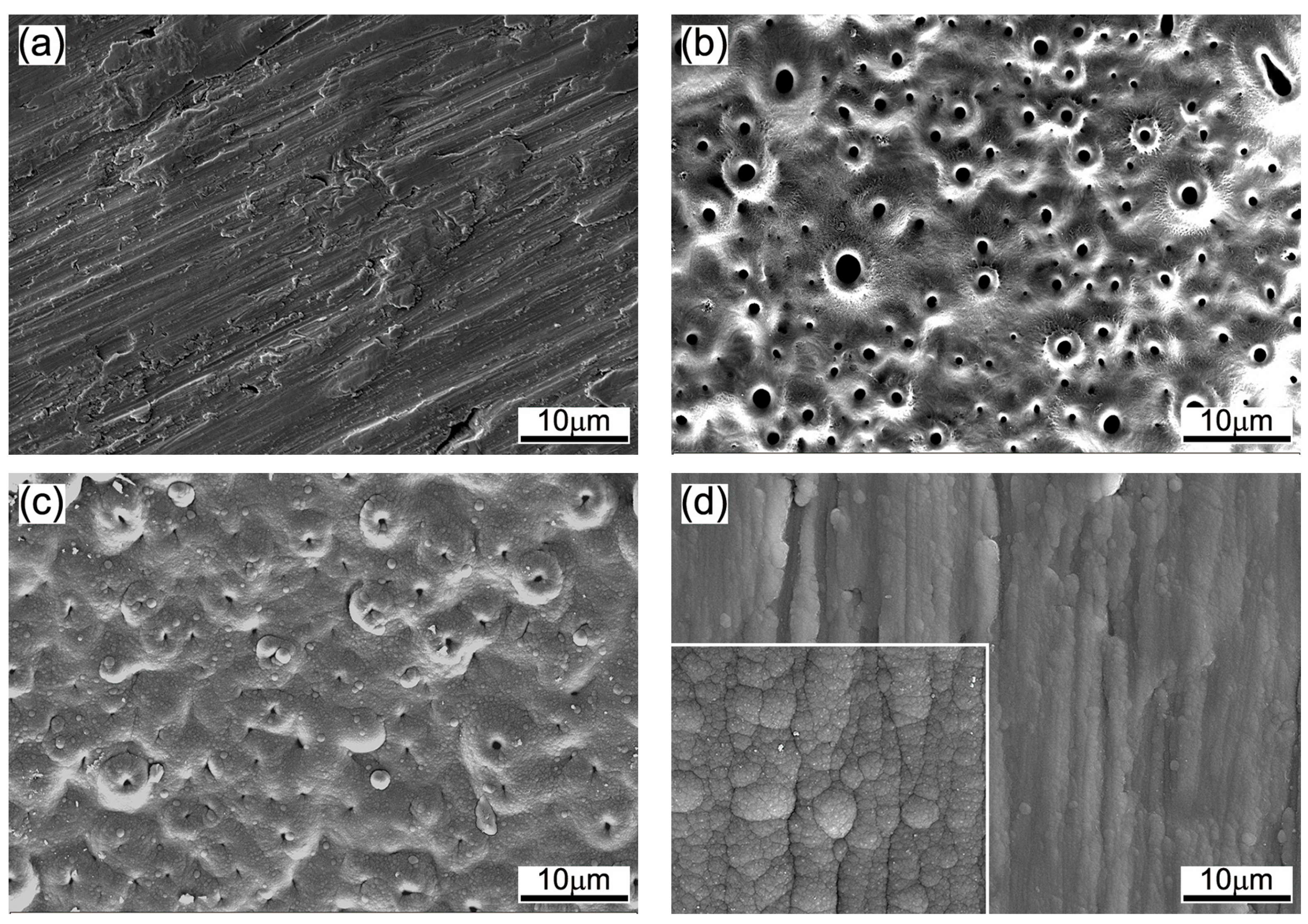
The surface morphologies of titanium substrate, spark-anodized titanium with/without the DLC deposition and DLC mono-film deposited directly onto the titanium substrate are shown in Figure 1. The SEM image of titanium substrate is shown in Figure 1a. Since the substrates were ground by sandpapers, the ploughed grooves and plastic deformation can be clearly observed, which reflects the relatively poor friction and wear properties of titanium. Figure 1b shows the typical morphology of anodic TiO2 film. It can be seen that the TiO2 film formed by spark-anodization exhibited a porous structure and surface micro-pores were distributed irregularly. These micro-pores similar to the craters were formed by the plasma discharges. The plasma discharges in the discharge channel resulted in local high temperature and high pressure, causing the molten material to eject from the film and then form circular pores and projections on the film surface [27,28]. Such porous structure led to high surface roughness (Ra = 477 ± 14 nm) of the TiO2 film and had a detrimental effect on the friction and wear properties of the film.
The surface morphology of the TiO2/DLC composite coating is shown in Figure 1c. After the DLC film deposition, the surface morphology of spark-anodized titanium was significantly changed. Most craters had been filled up with DLC materials and the micro-pore size and number decreased significantly. The micro-projections around the craters became less projecting out of the film surface due to the DLC deposition in the depression areas around the craters, leading to a decreased surface roughness (Ra = 352 ± 17 nm). This means that a relatively dense and smooth TiO2/DLC composite coating has been fabricated on the titanium substrate by the combined spark-anodization and magnetron sputtering techniques. Figure 1d shows the SEM image of the DLC mono-film deposited directly onto the titanium substrate. The DLC mono-film shows no significant defects such as micro-pores or micro-cracks. The high-magnification inset in Figure 1d shows that the DLC film had a dense structure consisting of tightly packed nanoparticles. These nanoparticles aggregated together and formed lots of microspheres. In addition, it can be found that the microspheres distributed along the ploughed grooves, indicating that the DLC mono-film inherited the surface morphology of the sandpaper-ground titanium substrate. The average surface roughness of the DLC mono-film was 259 ± 30 nm. The hardness and elastic modulus of the DLC mono-film determined by the Nano-indentation test was 21.89 ± 3.32 GPa and 186.45 ± 14.46 GPa, respectively. In contrast, the surface hardness of porous anodic oxide film is usually in the range of 3–6 GPa [27], which is lower than that of the DLC film. Therefore, the deposition of DLC film on the surface of anodic TiO2 film contributed to the improvement of surface hardness of spark-anodized titanium.
Figure 2a–c gives the cross-sectional morphologies of the anodic TiO2 film, TiO2/DLC composite coating and DLC mono-film, respectively. Figure 2d shows the element line-scanning analyses of the cross-sectional surface of TiO2/DLC composite coating. It can be seen from Figure 2a that the thickness of the anodic TiO2 film was inhomogeneous and the average thickness was 2.78 ± 0.66 µm. The bond of the TiO2 film to the substrate was formed by the plasma oxidation reaction, thus resulting in good bond strength. It can be observed from Figure 2b,d that the TiO2/DLC composite coating comprised three layers. The content of C element was very high on the top of the composite coating (Zone A), indicating the existence of DLC film here. While the elements of Ti, O and P were rich in the bottom film (Zone B), indicating that this was the anodic TiO2 film. The existence of P element in the anodic TiO2 film suggests that phosphate anions in the electrolyte were incorporated into the oxide film during the spark-anodization treatment of titanium. It was notable that there was a Zone C along the element distribution curves where C, Ti, O, P and Cr coexisted, as shown in Figure 2d. This is because the anodic TiO2 film had high porosity (see Figure 1b), which provided a pathway for introducing solid lubricant. When the DLC was deposited, the carbon atoms would fall into the micro-pores of anodic TiO2 film or deposited around the micro-projections, thus forming a hybrid film. The deposition of solid lubricant such as DLC was expected to improve the tribological performance of the anodic TiO2 film. The average thickness of the TiO2/DLC composite coating was 3.57 ± 0.44 µm. Figure 2c shows that the DLC mono-film deposited directly onto the titanium substrate had uniform and dense microstructure, and the average thickness of the DLC film was 1.03 ± 0.17 µm.
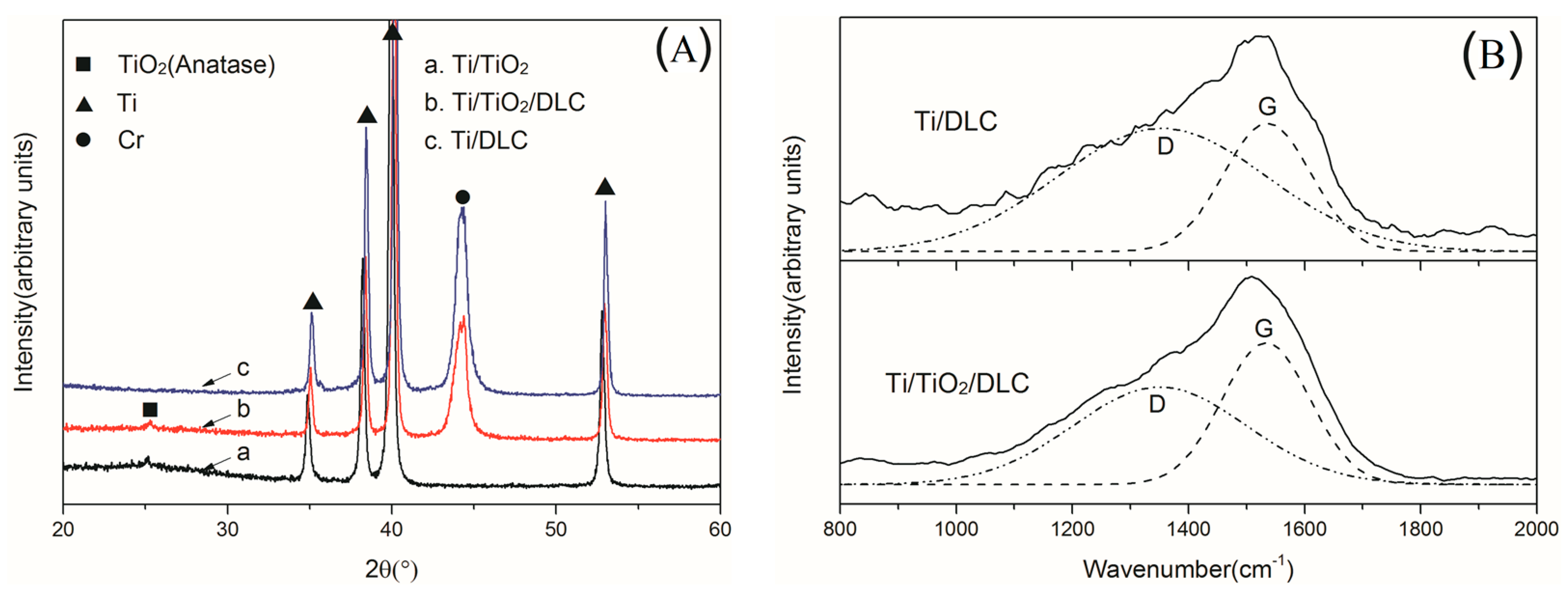
The XRD patterns of the Ti/TiO2, Ti/TiO2/DLC and Ti/DLC samples are shown in Figure 3A. The anatase phase was detected in the Ti/TiO2 and Ti/TiO2/DLC samples with a very weak peak at 25.3°, suggesting that the anodic TiO2 film was poorly-crystallized. The plasma discharges occurred during the spark-anodization treatment of titanium resulted in local high temperature and thus promoted the formation of anatase micro-crystallites [28]. The diffraction peaks at 35.1°, 38.4°, 40.2° and 53° were ascribed to the titanium substrate of coating samples and the diffraction peak at 44.2° corresponded to Cr transition layer in the Ti/DLC and Ti/TiO2/DLC samples. There was no XRD diffraction peak corresponding to the DLC film due to its amorphous structure. The Raman spectra of as-prepared DLC mono-film and TiO2/DLC composite coating are shown in Figure 3B. For these two samples, the Raman spectra were dominated by a broad asymmetric Raman scattering band between 800 and 1800 cm−1, representing the typical characteristic of DLC film [29]. The obtained spectra can be well fitted by two Gaussian distributions, situated at 1350 and 1530 cm−1 respectively. The band at around 1350 cm−1 is the so-called D band associated with the breathing vibrations of sp2 atoms in rings. The band at around 1530 cm−1 is the G band caused by the stretching vibration of sp2 atoms in both rings and chains [29].
3.2. Tribological Properties of Coatings on Titanium
3.2.1. Friction Coefficient
The tribological tests of the Ti/TiO2, Ti/TiO2/DLC and Ti/DLC samples against the counterpart GCr15 stainless steel ball were performed at room temperature using a ball-on-plate tribo-tester. The normal load of the tribo-test was selected as 1 N and 10 N, corresponding to light-load and heavy-load respectively.
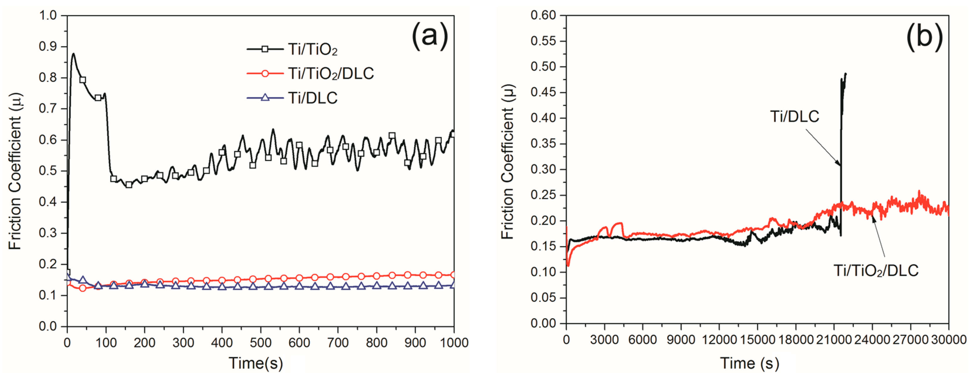
In the case of 1 N, the relationship between the friction coefficient and the wear time of samples is shown in Figure 4a. For the Ti/TiO2 sample, the friction coefficient curve exhibited significant fluctuation during the test. This was related to the unique structure of anodic TiO2 film. Previous studies have shown that the anodic TiO2 film fabricated with spark-anodization technique consists of a dense inner layer and a porous outer layer [30]. The dense inner layer located at the film/substrate interface and interlocked with the substrate with good adhesion [14]. The outer layer had a porous structure, which increased the surface roughness of anodic TiO2 film and impaired its mechanical properties such as the fracture toughness and strength. The dense inner layer usually had higher hardness and wear resistance than the porous outer layer [31]. The friction coefficient curve of Ti/TiO2 sample experienced an abrupt increase up to 0.88 and gradual decrease down to 0.73 at the initial stage. The gradual decrease of friction coefficient was mainly caused by two reasons. For one thing, the generated wear debris filled into the pores of the outer layer, which increased the contact area between the friction pair. For another, with the gradual worn-off of the porous outer layer, the counterpart ball began to contact with the harder and denser inner layer of anodic TiO2 film. Then, the friction coefficient reached a short-time plateau before the wear time of about 100 s, which indicated the steady friction between the counterpart ball and the dense inner layer. After the short-time plateau, the friction coefficient decreased to about 0.46 rapidly. The rapid decrease of friction coefficient at this stage was due to the removal of anodic TiO2 film from the substrate. After the whole TiO2 film had been removed from the substrate completely, the GCr15 ball came into contact with the titanium substrate directly. Since there existed many wear debris generated by the broken TiO2 film, the abrasive wear played a main role on the contact surface, resulting in relatively low and stable friction coefficient before 350 s. After that, the friction coefficient began to climb up to a mean value of about 0.55 with significant fluctuations, indicating that the titanium substrate suffered severe adhesive wear at the final stage.
For the Ti/TiO2/DLC sample, it can be seen from Figure 4a that the deposition of DLC on the anodic TiO2 film reduced the friction coefficient significantly. The friction coefficient remained about 0.15 during the overall sliding friction and wear test. It can be noted that at the initial stage of the test, the friction coefficient underwent a gradual and slight decrease before the wear time of about 100 s. This is because micro-projections on the composite coating surface were worn off gradually at this stage. After that, the friction coefficient climbed up slightly to about 0.15 and then remained stable until the end of the test. It is evident that the deposition of DLC on the anodic TiO2 film improved the tribological performance of spark-anodized titanium significantly. Compared with the anodic TiO2 film, the low friction coefficient of the TiO2/DLC composite coating arose from the high hardness of composite coating and the self-lubricating graphite transfer layer formed at the interface during the wear test [32]. The transfer layer was formed by the phase transformation of the DLC film from diamond-like structure to graphite structure during the wear process and the transfer layer was more easily formed with the aid of the localized rising temperature at asperity contacts [33].
For the Ti/DLC sample, it had similar friction coefficient curve with the composite coating, as shown in Figure 4a. At the running-in wear stage of the Ti/DLC sample, the friction coefficient was about 0.15. After that, the friction coefficient decreased to about 0.12 and remained stable until the end of the test. During the running-in wear process, the contact surface of the friction pair became smoother gradually due to the friction-induced flattening of the counterpart ball and the surface polishing of DLC film. As mentioned above, the DLC film has a metastable structure and it will be transformed into graphite structure after overcoming the energy barrier [32]. Thus, the interface graphitization reduced the friction coefficient. Compared with DLC film deposited directly onto the titanium substrate, the composite coating exhibited a slightly higher friction coefficient. This was associated with the different surface roughness of the DLC mono-film and the composite coating [16]. The average surface roughness of the composite coating (Ra = 352 ± 17 nm) was higher than that of the DLC mono-film (Ra = 259 ± 30 nm).
When the normal load was 10 N, the relationship between the friction coefficient and the wear time of the Ti/TiO2/DLC and Ti/DLC samples is shown in Figure 4b. It can be seen that the composite coating and the DLC mono-film had almost the same trend as to the friction coefficient curve before the wear time of 13,000 s except that the friction coefficient of the composite coating exhibited fluctuations during the period of 3000–4000 s. This indicates that the DLC film on the surface of the two samples played a major role within this wear time. The friction coefficient fluctuation of the composite coating was caused by the porous surface structure of the anodic TiO2 film. After 13,000 s, most of the DLC film on the surface of two samples has been consumed. At this stage, the friction coefficient curve of two samples demonstrated a climbing trend with significant fluctuations. To be specific, the friction coefficient of the DLC mono-film gradually increased to an average value of about 0.18 before the final sharp spike at about 21,000 s, while the friction coefficient of the composite coating gradually increased to an average value of about 0.23 until the end of the test. Three possible reasons contributed to the climbing trend in the friction coefficient [34,35]. First, the friction induced the oxidation of the hydrogen-containing DLC film [34]. This reaction transformed the surface chemical state of DLC film from hydrogen-containing to oxygen-containing groups. Thus, the interaction energy of the contact surface was increased so that the shear force increased during the friction process and then the friction coefficient increased [35]. Another possible reason was that the activated Fe atoms and C atoms formed Fe–C bonds under the action of friction. This reaction caused strong adhesive wear at the contact surfaces, resulting in increased friction coefficient with fluctuations [35]. Furthermore, as the wear time was further extended, the graphite-like transfer layer of the wear contact surface reduced gradually, causing the friction coefficient to rise.
At 21,000 s, the friction coefficient of the DLC mono-film increased abruptly to 0.5, indicating that the DLC film had been worn off from the titanium substrate completely. However, the composite coating was not worn-off until the end of the test. In general, the friction coefficient of DLC film decreases with the increase of substrate hardness and a substrate with higher hardness is beneficial to the wear life [36]. The surface hardness of the titanium substrate was improved by the formation of the anodic TiO2 film, which reduced the deformation of the substrate during the friction process and improved the load-bearing capacity of the coating [37]. The wear life of the TiO2/DLC composite coating was increased about 43% relative to the DLC mono-film, as shown in Figure 4b. Based on above results and analysis, it can be concluded that the DLC deposition on the surface of the anodic TiO2 film significantly reduced the friction coefficient of anodic TiO2 film and improved the wear life.
3.2.2. Wear Properties
Figure 5a–c presents the optical microscope images of wear tracks of Ti/TiO2, Ti/TiO2/DLC and Ti/DLC samples after a sliding distance of 100 m under normal load of 1 N. The cross-sectional profiles of wear tracks are shown in Figure 5d. For the Ti/TiO2 sample, it can be seen from Figure 5a that the width of the wear track was uneven. In addition, there were a large number of ploughed grooves and wear debris in the wear track. The cross-sectional profile showed that the wear track was broad and deep (up to about 50 μm, see Figure 5d). This means that the titanium substrate had been exposed during the test since the total thickness of anodic TiO2 film was only about 3 μm. This result was consistent with the friction coefficient curve of Ti/TiO2 sample shown in Figure 4a. These results indicate that the TiO2 film had been worn off quickly under the wear conditions of normal load of 1 N and the wear distance of 100 m, resulting in severe wear of substrate during the wear process, leading to large fluctuation of the friction coefficient after 400 s (Figure 4a). Apparently, the anodic TiO2 mono-film had no significant improvement on the friction and wear protection of the titanium substrate. For the Ti/TiO2/DLC sample, its wear track was much narrower and shallower than that of the Ti/TiO2 sample, as shown in Figure 5a,b. The cross-sectional wear profile (Figure 5d) of the Ti/TiO2/DLC sample looks like a straight line, indicating that the wear of the composite coating under the light load of 1 N was very small and near zero. This demonstrates that the deposition of DLC film on the Ti/TiO2 sample significantly improved the wear properties of spark-anodized titanium. For the Ti/DLC sample, its wear track and profile were similar to the Ti/TiO2/DLC sample and both samples exhibited narrow and shallow wear track under the light load of 1 N. This is due to the high hardness of the DLC film on the surface.
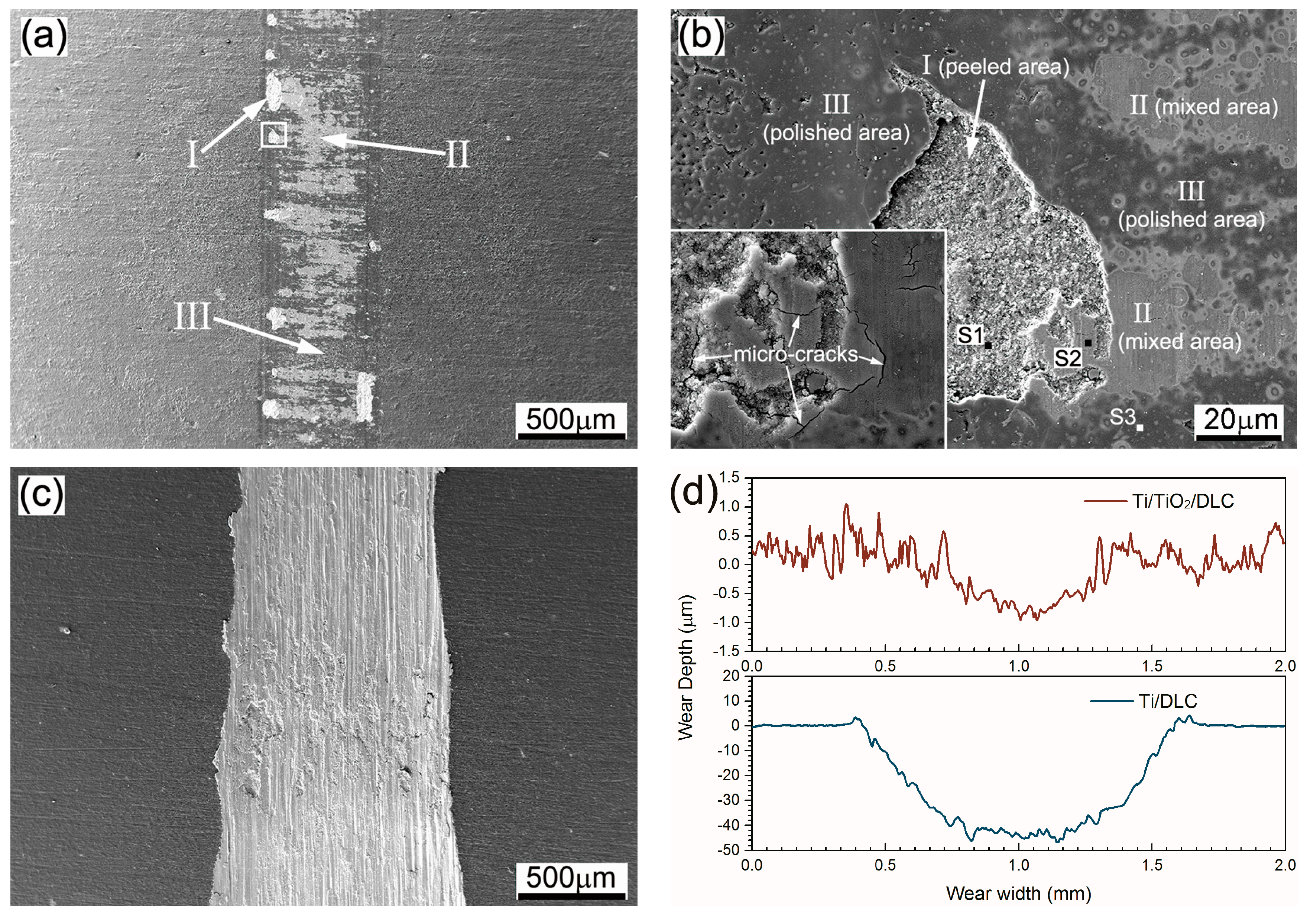
Figure 6 displays the SEM images of wear tracks of the Ti/TiO2/DLC and Ti/DLC samples against GCr15 ball after a sliding distance of 1000 m under normal load of 10 N. The element composition of wear track of the Ti/TiO2/DLC sample was examined by EDS after the friction tests and results are listed in Table 1. For the worn track of Ti/TiO2/DLC sample, it can be seen from Figure 6a that there were three kinds of typical worn surface morphologies and Figure 6b gives the enlargement of these three kinds of typical morphologies. The first worn surface morphology was the peeled area where some local damages took place at the edge of the wear track, as marked by arrow I in Figure 6a,b. The main chemical element in the peeled area was Ti besides a little Fe and O deriving from the wear debris (see Table 1 and area S1 in Figure 6b). It indicates that the TiO2/DLC composite coating peeled off from the substrate in this area and exposed the titanium substrate underneath. This agrees with the reported results [38,39]. The peel-off was caused by the combination of brittle fracture and fatigue fracture under the cyclic stress during the sliding test. The composite coating was brittle compared to the ductile metal substrate and so it was easy to fracture under heavy load [40]. During the friction and wear test, the coating suffered from unbalanced compressive stress at the edge of the wear track, causing a brittle fracture of the composite coating in this area.
For the second worn surface morphology, as marked by arrow II in Figure 6a,b, a lot of O and Fe elements as well as small quality of C element were detected at area S2, which indicated that the materials transferred from GCr15 counterpart to the composite coating surface and the formation of ferrous oxides occurred during the process of wear. This worn surface morphology was described as the mixed area. Such mixed area was widespread in the middle of the worn track. The local enlargement inset in Figure 6b shows that there were some micro-cracks in mixed area. The initiation of these micro-cracks was triggered by the combined loading of compressive and shear stress during the sliding test [27,39]. These micro-cracks would propagate into the interior of the coating under the cyclic stress and eventually caused the detachment of the composite coating.
Besides the peeled area and mixed area, there were some smooth areas in the wear track, as marked by arrow III in Figure 6a,b, which looked like the polished surface. Therefore, this smooth area was described as the polished area. In this area (S3), a large number of C element and small quality of O and Fe element were detected, indicating that the DLC film was still present here. The DLC film formed a transfer layer with low shear strength at the sliding interface during the wear process [41]. This reduced the shear and adhesive stresses between contact surfaces and thus alleviated the formation of micro-cracks and fractures during the friction process.
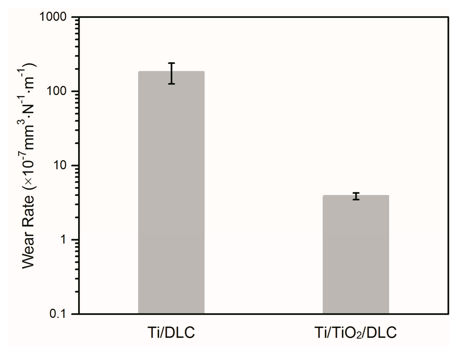
In the case of Ti/DLC sample, as shown in Figure 6c, it can be seen that there were a large number of ploughed grooves and ridges parallel to the sliding direction on the worn surface. Meanwhile, plastic deformation and adhesive wear can also be observed. Actually, such a severe wear had occurred shortly after the failure and removal of the DLC mono-film. The cross-sectional profiles of the wear tracks of the Ti/TiO2/DLC and Ti/DLC samples are shown in Figure 6d. It can be observed from Figure 6d that the wear track of Ti/TiO2/DLC sample was very shallow after the sliding test, while the Ti/DLC sample exhibited much deeper and wider wear track than the Ti/TiO2/DLC sample. The wear rate of the Ti/TiO2/DLC sample and Ti/DLC sample were calculated to be 3.89 × 10⁻⁷ and 1.83 × 10⁻⁵ mm3∙N−1∙m−1, respectively (Figure 7). The error bars represent the standard deviation of six measurements. The wear rate of the Ti/TiO2/DLC sample was lower than that of the Ti/DLC sample, indicating the composite coating exhibited excellent wear resistance.
4. Conclusions
The TiO2/DLC composite coating was successfully fabricated on titanium substrate using the combined spark-anodization and DC unbalanced magnetron sputtering techniques. After the DLC deposition, the surface microstructure of spark-anodized titanium was changed significantly. The micro-pore size and surface roughness of spark-anodized titanium decreased and the fabricated TiO2/DLC composite coating consisted of top DLC film, middle hybrid film and bottom TiO2 film.
The fabricated TiO2/DLC composite coating exhibited more stable and much lower friction coefficient than anodic TiO2 mono-film. Although the friction coefficient of the composite coating and the DLC mono-film was similar under both light load and heavy load conditions, the wear life of the composite coating was about 43% longer than that of DLC mono-film under heavy load condition because the bottom TiO2 film provided necessary hardness and load support. The wear rate of titanium with protective composite coating was much lower than that of titanium with DLC mono-film. This study indicates that the advanced wear protection of Ti alloys could be achieved by the TiO2/DLC composite coating prepared by the combined spark-anodization and magnetron sputtering techniques.
Acknowledgments
This work is supported by Natural Science Foundation of Hebei Province (E2016203270), Specialized Foundation for the Development of Military-civilian Combination Industry of Hebei Province (2017B110), and Fundamental Research Foundation (020000904) and Doctoral Foundation (B942) of Yanshan University.
Author Contributions
Zhaoxiang Chen and Limei Ren conceived and designed the experiments; Xipeng Ren and Tengchao Wang performed the experiments; Zhaoxiang Chen, Xipeng Ren and Limei Ren analyzed the data and wrote the paper; Xiaowen Qi and Yulin Yang contributed materials/analysis tools and paper revision.
Conflicts of Interest
The authors declare no conflict of interest.
References
- Kruthiventi, S.S.; Subbarao, R.; Inturi, D.M.; Gujjula, R. Influence of heat treatment on mechanical and micro structural properties of titanium alloys for enhanced applications. Mater. Today Proc. 2017, 4, 8111–8116. [Google Scholar] [CrossRef]
- Lepicka, M.; Gradzka-Dahlke, M. Surface modification of Ti6Al4V titanium alloy for biomedical applications and its effect on tribological performance—A review. Rev. Adv. Mater. Sci. 2016, 46, 86–103. [Google Scholar]
- Mogonye, J.E.; Scharf, T.W. Tribological properties and mechanisms of self-mated ultrafine-grained titanium. Wear 2017, 376, 931–939. [Google Scholar] [CrossRef]
- Shan, L.; Wang, Y.; Li, J.; Li, H.; Wu, X.; Chen, J. Tribological behaviours of PVD TiN and TiCN coatings in artificial seawater. Surf. Coat. Technol. 2013, 226, 40–50. [Google Scholar] [CrossRef]
- Marin, E.; Offoiach, R.; Regis, M.; Fusi, S.; Lanzutti, A.; Fedrizzi, L. Diffusive thermal treatments combined with PVD coatings for tribological protection of titanium alloys. Mater. Des. 2016, 89, 314–322. [Google Scholar] [CrossRef]
- Fernandes, B.B.; Oliveira, R.M.; Ueda, M.; de Fátima Magalhães Mariano, S.; Ramos, A.S.; Vieira, M.S.; de Melo, F.C.L.; de Oliveira, G. Effects of high temperature plasma immersion ion implantation on wear resistance of Ti-Si-B sintered alloys. Surf. Coat. Technol. 2013, 228, 195–200. [Google Scholar] [CrossRef]
- Wang, S.; Liao, Z.; Liu, Y.; Liu, W. Influence of thermal oxidation temperature on the microstructural and tribological behavior of Ti6Al4V alloy. Surf. Coat. Technol. 2014, 240, 470–477. [Google Scholar] [CrossRef]
- Wen, M.; Wen, C.; Hodgson, P.; Li, Y. Improvement of the biomedical properties of titanium using SMAT and thermal oxidation. Colloids Surf. B Biointerfaces 2014, 116, 658–665. [Google Scholar] [CrossRef] [PubMed]
- Liu, X.-B.; Meng, X.-J.; Liu, H.-Q.; Shi, G.-L.; Wu, S.-H.; Sun, C.-F.; Wang, M.-D.; Qi, L.-H. Development and characterization of laser clad high temperature self-lubricating wear resistant composite coatings on Ti–6Al–4V alloy. Mater. Des. 2014, 55, 404–409. [Google Scholar] [CrossRef]
- Shokouhfar, M.; Allahkaram, S.R. Effect of incorporation of nanoparticles with different composition on wear and corrosion behavior of ceramic coatings developed on pure titanium by micro arc oxidation. Surf. Coat. Technol. 2017, 309, 767–778. [Google Scholar] [CrossRef]
- Wheeler, J.M.; Collier, C.A.; Paillard, J.M.; Curran, J.A. Evaluation of micromechanical behaviour of plasma electrolytic oxidation (PEO) coatings on Ti–6Al–4V. Surf. Coat. Technol. 2010, 204, 3399–3409. [Google Scholar] [CrossRef]
- Habazaki, H.; Tsunekawa, S.; Tsuji, E.; Nakayama, T. Formation and characterization of wear-resistant PEO coatings formed on β-titanium alloy at different electrolyte temperatures. Appl. Surf. Sci. 2012, 259, 711–718. [Google Scholar] [CrossRef]
- Yetim, A.F. Investigation of wear behavior of titanium oxide films, produced by anodic oxidation, on commercially pure titanium in vacuum conditions. Surf. Coat. Technol. 2010, 205, 1757–1763. [Google Scholar] [CrossRef]
- Chen, Z.X.; Wang, W.X.; Takao, Y.; Matsubara, T.; Ren, L.M. Microstructure and shear fracture characteristics of porous anodic TiO2 layer before and after hot water treatment. Appl. Surf. Sci. 2011, 257, 7254–7262. [Google Scholar] [CrossRef]
- Sundararajan, G.; Rama Krishna, L. Mechanisms underlying the formation of thick alumina coatings through the MAO coating technology. Surf. Coat. Technol. 2003, 167, 269–277. [Google Scholar] [CrossRef]
- Svahn, F.; Kassman-Rudolphi, Å.; Wallén, E. The influence of surface roughness on friction and wear of machine element coatings. Wear 2003, 254, 1092–1098. [Google Scholar] [CrossRef]
- Mu, M.; Zhou, X.; Xiao, Q.; Liang, J.; Huo, X. Preparation and tribological properties of self-lubricating TiO2/graphite composite coating on Ti6Al4V alloy. Appl. Surf. Sci. 2012, 258, 8570–8576. [Google Scholar] [CrossRef]
- Ao, N.; Liu, D.; Wang, S.; Zhao, Q.; Zhang, X.; Zhang, M. Microstructure and tribological behavior of a TiO2/hBN composite ceramic coating formed via micro-arc oxidation of Ti–6Al–4V alloy. J. Mater. Sci. Technol. 2016, 32, 1071–1076. [Google Scholar] [CrossRef]
- Yin, B.; Peng, Z.; Liang, J.; Jin, K.; Zhu, S.; Yang, J.; Qiao, Z. Tribological behavior and mechanism of self-lubricating wear-resistant composite coatings fabricated by one-step plasma electrolytic oxidation. Tribol. Int. 2016, 97, 97–107. [Google Scholar] [CrossRef]
- Ali, E.; Christophe, D. Tribology of diamond-like carbon films: Recent progress and future prospects. J. Phys. D Appl. Phys. 2006, 39, R311–R327. [Google Scholar]
- Sutton, D.C.; Limbert, G.; Burdett, B.; Wood, R.J.K. Interpreting the effects of interfacial chemistry on the tribology of diamond-like carbon coatings against steel in distilled water. Wear 2013, 302, 918–928. [Google Scholar] [CrossRef]
- Bhowmick, S.; Banerji, A.; Lukitsch, M.J.; Alpas, A.T. The high temperature tribological behavior of Si, O containing hydrogenated diamond-like carbon (a-C:H/a-Si:O) coating against an aluminum alloy. Wear 2015, 330, 261–271. [Google Scholar] [CrossRef]
- Banerji, A.; Bhowmick, S.; Alpas, A.T. High temperature tribological behavior of W containing diamond-like carbon (DLC) coating against titanium alloys. Surf. Coat. Technol. 2014, 241, 93–104. [Google Scholar] [CrossRef]
- Zhao, F.; Li, H.; Ji, L.; Wang, Y.; Zhou, H.; Chen, J. Ti-DLC films with superior friction performance. Diam. Relat. Mater. 2010, 19, 342–349. [Google Scholar] [CrossRef]
- Maiti, R.; Mills, R. Wear properties of diamond-like carbon coatings with silicon and chromium as adhesion layer using a high frequency reciprocating rig. Proc. Inst. Mech. Eng. Part J J. Eng. Tribol. 2017, 231, 1605–1615. [Google Scholar] [CrossRef]
- Uematsu, Y.; Kakiuchi, T.; Adachi, M.; Shinohara, T. Effect of interlayer thickness on fatigue behavior in A5052 aluminum alloy with diamond-like carbon/anodic-oxide hybrid coating. Mater. Trans. 2015, 56, 1793–1799. [Google Scholar] [CrossRef]
- Yerokhin, A.L.; Nie, X.; Leyland, A.; Matthews, A. Characterisation of oxide films produced by plasma electrolytic oxidation of a Ti–6Al–4V alloy. Surf. Coat. Technol. 2000, 130, 195–206. [Google Scholar] [CrossRef]
- Chen, Z.; Zhou, K.; Lu, X.; Lam, Y.C. Influence of hydrothermal exposure on surface characteristics and corrosion behaviors of anodized titanium. Surf. Interface Anal. 2014, 46, 307–313. [Google Scholar] [CrossRef]
- Robertson, J. Diamond-like amorphous carbon. Mater. Sci. Eng. R Rep. 2002, 37, 129–281. [Google Scholar] [CrossRef]
- Quintero, D.; Galvis, O.; Calderón, J.A.; Castaño, J.G.; Echeverría, F. Effect of electrochemical parameters on the formation of anodic films on commercially pure titanium by plasma electrolytic oxidation. Surf. Coat. Technol. 2014, 258, 1223–1231. [Google Scholar] [CrossRef]
- Krishna, L.R.; Gupta, P.S.V.N.B.; Sundararajan, G. The influence of phase gradient within the micro arc oxidation (MAO) coatings on mechanical and tribological behaviors. Surf. Coat. Technol. 2015, 269, 54–63. [Google Scholar] [CrossRef]
- Liu, Y.A.N.; Meletis, E.I. Evidence of graphitization of diamond-like carbon films during sliding wear. J. Mater. Sci. 1997, 32, 3491–3495. [Google Scholar] [CrossRef]
- Zou, Y.S.; Wu, Y.F.; Yang, H.; Cang, K.; Song, G.H.; Li, Z.X.; Zhou, K. The microstructure, mechanical and friction properties of protective diamond like carbon films on magnesium alloy. Appl. Surf. Sci. 2011, 258, 1624–1629. [Google Scholar] [CrossRef]
- Li, H.; Xu, T.; Wang, C.; Chen, J.; Zhou, H.; Liu, H. Tribochemical effects on the friction and wear behaviors of a-C:H and a-C films in different environment. Tribol. Int. 2007, 40, 132–138. [Google Scholar] [CrossRef]
- Li, H.; Xu, T.; Wang, C.; Chen, J.; Zhou, H.; Liu, H. Tribochemical effects on the friction and wear behaviors of diamond-like carbon film under high relative humidity condition. Tribol. Lett. 2005, 19, 231–238. [Google Scholar] [CrossRef]
- Meletis, E.I.; Erdemir, A.; Fenske, G.R. Tribological characteristics of DLC films and duplex plasma nitriding/DLC coating treatments. Surf. Coat. Technol. 1995, 73, 39–45. [Google Scholar] [CrossRef]
- Voevodin, A.A.; Capano, M.A.; Laube, S.J.P.; Donley, M.S.; Zabinski, J.S. Design of a Ti/TiC/DLC functionally gradient coating based on studies of structural transitions in Ti–C thin films. Thin Solid Films 1997, 298, 107–115. [Google Scholar] [CrossRef]
- Xue, W.; Tian, H.; Du, J.; Hua, M.; Zhang, X.; Li, Y. Duplex Al2O3/DLC coating on 15SiCP/2024 aluminum matrix composite using combined microarc oxidation and filtered cathodic vacuum arc deposition. Surf. Rev. Lett. 2012, 19, 1250036. [Google Scholar] [CrossRef]
- Chen, Y.; Wu, J.-M.; Nie, X.; Yu, S. Study on failure mechanisms of DLC coated Ti6Al4V and CoCr under cyclic high combined contact stress. J. Alloys Compd. 2016, 688, 964–973. [Google Scholar] [CrossRef]
- Tao, X.; Yao, Z.; Luo, X. Comparison of tribological and corrosion behaviors of Cp Ti coated with the TiO2/graphite coating and nitrided TiO2/graphite coating. J. Alloys Compd. 2017, 718, 126–133. [Google Scholar] [CrossRef]
- Donnet, C. Recent progress on the tribology of doped diamond-like and carbon alloy coatings: A review. Surf. Coat. Technol. 1998, 100–101, 180–186. [Google Scholar] [CrossRef]
Figure 1.
Surface morphologies of (a) titanium substrate, (b) anodic TiO2 film, (c) TiO2/diamond-like carbon (DLC) composite coating, and (d) DLC mono-film.
Figure 1.
Surface morphologies of (a) titanium substrate, (b) anodic TiO2 film, (c) TiO2/diamond-like carbon (DLC) composite coating, and (d) DLC mono-film.

Figure 2.
Cross-sectional morphologies and element analyses of coatings: (a) anodic TiO2 film; (b) TiO2/DLC composite coating; (c) DLC mono-film; (d) element line-scanning analyses of the cross-sectional surface of TiO2/DLC composite coating.
Figure 2.
Cross-sectional morphologies and element analyses of coatings: (a) anodic TiO2 film; (b) TiO2/DLC composite coating; (c) DLC mono-film; (d) element line-scanning analyses of the cross-sectional surface of TiO2/DLC composite coating.
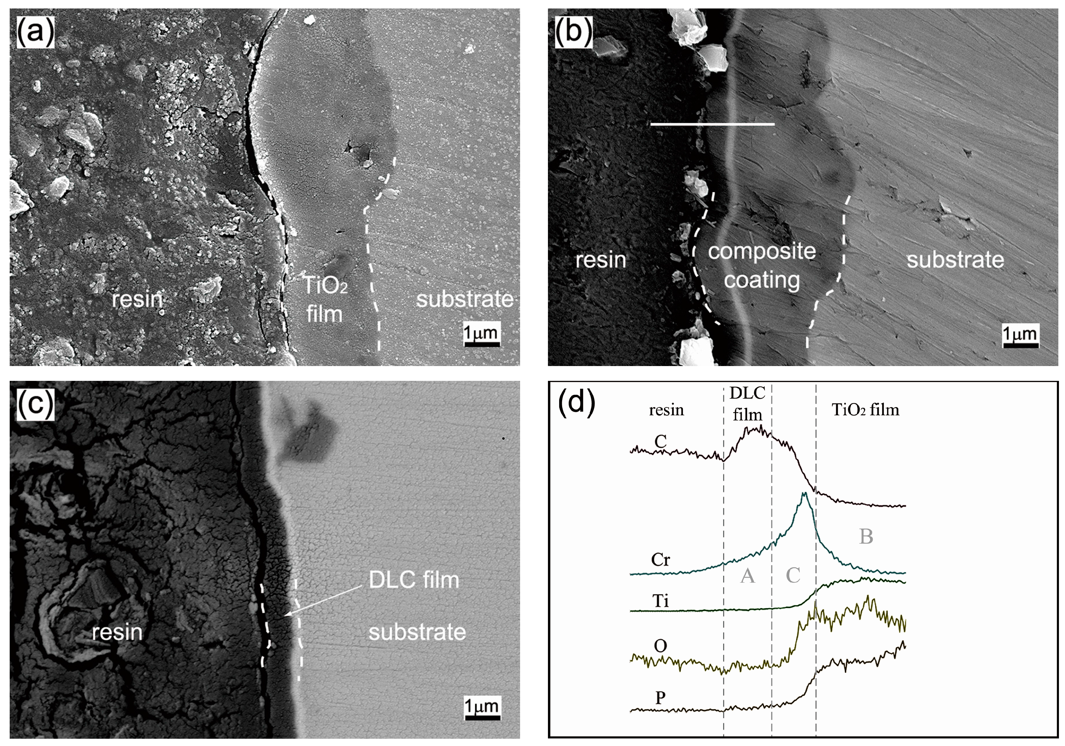
Figure 3.
(A) X-ray diffraction (XRD) patterns and (B) Raman spectra of the coating samples.

Figure 4.
The relationship between the friction coefficient and the wear time of samples under different normal load: (a) 1 N; (b) 10 N.
Figure 4.
The relationship between the friction coefficient and the wear time of samples under different normal load: (a) 1 N; (b) 10 N.

Figure 5.
Optical microscope images and cross-sectional profiles of wear tracks of samples after a sliding distance of 100 m under normal load of 1 N: (a) Ti/TiO2; (b) Ti/TiO2/DLC; (c) Ti/DLC; (d) cross-sectional profiles of wear tracks.
Figure 5.
Optical microscope images and cross-sectional profiles of wear tracks of samples after a sliding distance of 100 m under normal load of 1 N: (a) Ti/TiO2; (b) Ti/TiO2/DLC; (c) Ti/DLC; (d) cross-sectional profiles of wear tracks.
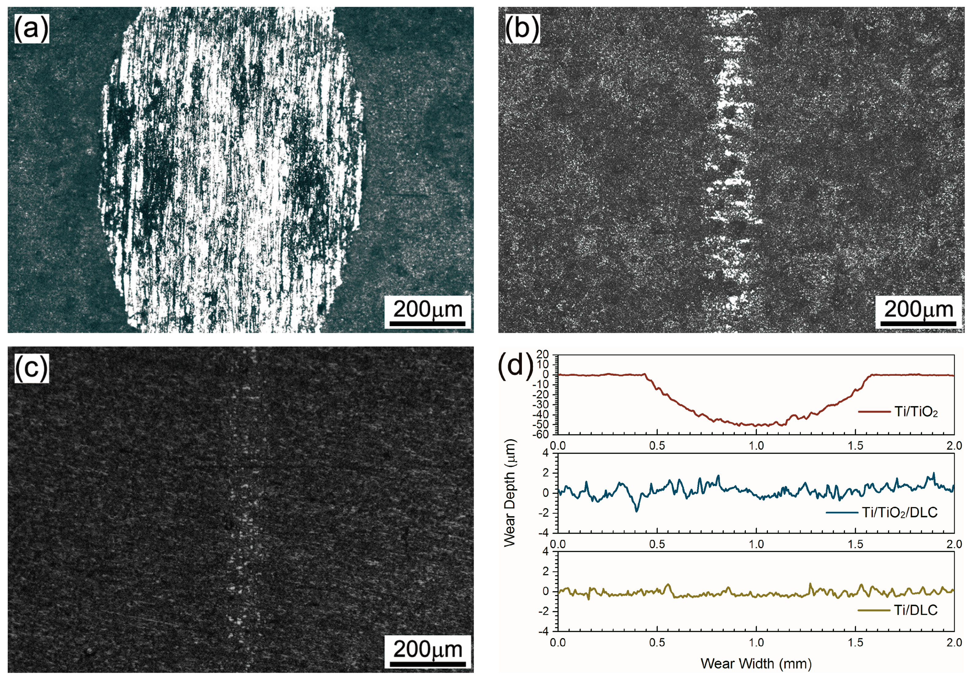
Figure 6.
SEM images and cross-sectional profiles of wear tracks after a sliding distance of 1000 m under normal load of 10 N: (a) Ti/TiO2/DLC sample; (b) the enlargement of three kinds of typical morphologies of Ti/TiO2/DLC sample wear track; (c) Ti/DLC sample; (d) cross-sectional profiles of wear tracks.

Figure 7.
Wear rate of samples under normal load 10 N.


Table 1.
The element composition of wear track of the Ti/TiO2/DLC sample.
| Area | Element (wt %) | |||||
|---|---|---|---|---|---|---|
| C | O | P | Ti | Cr | Fe | |
| S1 | 0.94 | 9.81 | 1.93 | 86.08 | – | 1.24 |
| S2 | 2.98 | 16.90 | 1.60 | 9.02 | 5.54 | 63.97 |
| S3 | 34.68 | 2.05 | – | 16.86 | 45.75 | 0.66 |
© 2018 by the authors. Licensee MDPI, Basel, Switzerland. This article is an open access article distributed under the terms and conditions of the Creative Commons Attribution (CC BY) license (http://creativecommons.org/licenses/by/4.0/).
Share and Cite
MDPI and ACS Style
Chen, Z.; Ren, X.; Ren, L.; Wang, T.; Qi, X.; Yang, Y. Improving the Tribological Properties of Spark-Anodized Titanium by Magnetron Sputtered Diamond-Like Carbon. Coatings 2018, 8, 83. https://doi.org/10.3390/coatings8020083
AMA Style
Chen Z, Ren X, Ren L, Wang T, Qi X, Yang Y. Improving the Tribological Properties of Spark-Anodized Titanium by Magnetron Sputtered Diamond-Like Carbon. Coatings. 2018; 8(2):83. https://doi.org/10.3390/coatings8020083
Chicago/Turabian StyleChen, Zhaoxiang, Xipeng Ren, Limei Ren, Tengchao Wang, Xiaowen Qi, and Yulin Yang. 2018. "Improving the Tribological Properties of Spark-Anodized Titanium by Magnetron Sputtered Diamond-Like Carbon" Coatings 8, no. 2: 83. https://doi.org/10.3390/coatings8020083
Note that from the first issue of 2016, this journal uses article numbers instead of page numbers. See further details here.