New Method to Identify Field Joint Coating Failures Based on MFL In-Line Inspection Signals

1
School of Materials Science and Engineering, Tianjin University, Tianjin 300072, China
2
PetroChina Pipeline Company, Langfang 065000, China
*
Author to whom correspondence should be addressed.
Coatings 2018, 8(3), 86; https://doi.org/10.3390/coatings8030086
Submission received: 6 January 2018
/
Revised: 8 February 2018
/
Accepted: 24 February 2018
/
Published: 27 February 2018
(This article belongs to the Special Issue Advanced Nondestructive Evaluation and Characterization of Surface)
Abstract
:Above ground indirect detections and random excavations that have applied the past years for buried long distance oil and gas pipelines can only identify some damaged coating locations. Hence, large number of field joint coating (FJC) failures happen unconsciously until they lead to failures of the pipelines. Based on the analysis of magnetic flux leakage (MFL) in-line inspection (ILI) signals, combined with the statistical results of 414 excavations from two different pipeline sections, a new method to identify the failed FJC is established. Though it can only identify FJC failures when there are signs of corrosion on pipe body, it is much more efficient and cost-saving. The concluded identification rule still needs more validations and improvements to be more applicable and accuracy.
1. Introduction
Maintaining high-pressure oil and gas pipeline system safe and reliable is very important because the products transported through pipelines are hazardous, and may lead to high consequence accidents [1,2]. According to the pipeline failure investigation reports of Pipeline and Hazardous Materials Safety Administration (PHMSA), corrosion is always an important factor. Pipeline coatings form a barrier between the corrosive substances in the soil surrounding the pipeline and the metal pipe in order to prevent the developing of external corrosions [3,4,5]. Pipe body’s coatings are applied in factory with relatively high quality; while field wrap around the girth weld should be strictly processed to ensure the pipeline integrity because of the coating joint’s weakness and field uncontrollable factors [6].
During the past years, above-ground indirect detections and selectively excavations for buried long distance oil & gas pipelines have been applied to identify the failure of field joint coating (FJC), in order to avoid the occurrence of corrosion in advance [7,8]. However, detections can only identify some damaged coating locations. For other cases, such as coatings that are debond from pipeline body with no damage, they can hardly identify, especially for FJC. The selectively excavations are also costly and inefficient. Hence, failures of FJC will happen unconsciously until they lead to failures of the pipelines (shown in Figure 1).
The causes for the corrosion failure of coatings may be ascribed to that the ground water permeated into the insulating layer to produce the enclosed corrosion environment [9]. In recent years, PetroChina Pipeline Company has found numbers of serious external corrosions due to failed FJCs. When FJC is debonded from the pipe without damages, cathodic protection is always shielded, which may cause crevice corrosion and also microbiological corrosion with rapid wall thickness thinning speed [10,11,12,13,14]. Consequently, it is important to identify external corrosion that is caused by failed FJC in advance.
Researchers try to find a direct way to detect the failures of FCJ. It is reported that with the continued development and improvements of the “Electro-Magnetic Acoustic Transducer” (EMAT) in line inspection (ILI) technology, it is possible to locate disbanded coatings, without the need of exposing the pipeline [15]. It is also reported that there is a method for in-situ detection of coating defects on a buried pipeline [16]. These works are still in research, and needs to run new tool, which will add to the costs. In this paper, based on the analysis of widely used magnetic flux leakage (MFL) ILI signals, combined with the statistical results of excavations, a new method to identify the failed FJC is established. This method can be applied during periodic MFL ILI, which is widely used all around the world by operators, so it is very convenient and efficient. As the method finds FCJ failures based on the reported defects, which shows the occurrence of corrosion, it is with high accuracy and low cost.
2. Features of MFL Signals
MFL ILI tools used to detect, locate, and size pipeline anomalies, such as metal loss, dents, and ferrous metal objects, are based on the change of magnetic flux leakage in air near the pipe wall detected by the hall sensor (shown in Figure 2) [17,18,19].
Though it will be affected by piping stress deformation, cleanness of pipeline, lift off of probe, and the vibration when tool running, the accuracy and resolution of this technology is industrially accepted and world-widely used [20,21].
It is found that when focusing on the field joint areas, signal analysis can help to identify coating failure based on the corrosion reported in this zone. According to the distributions and patterns of the external corrosions reported in the field wrap regions, which is of a certain distance to the girth weld from upstream to downstream, signal types can be categorized into three types:
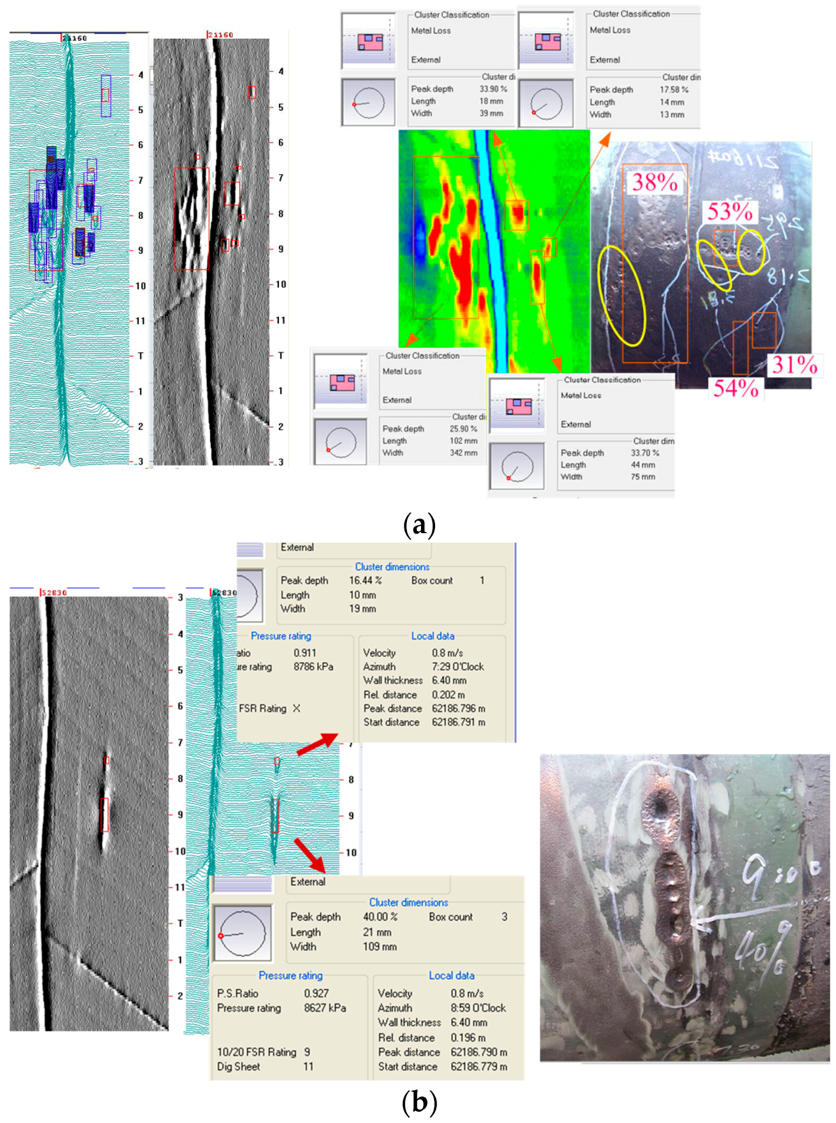
Type 1: Defects cluster together as a band or a ring, or one single corrosion depth is more than 20% wall thickness (WT), as shown in Figure 3. This type is the most likely failed FJCs according to the mechanism when corrosion begins to occur under the disbanding coatings.
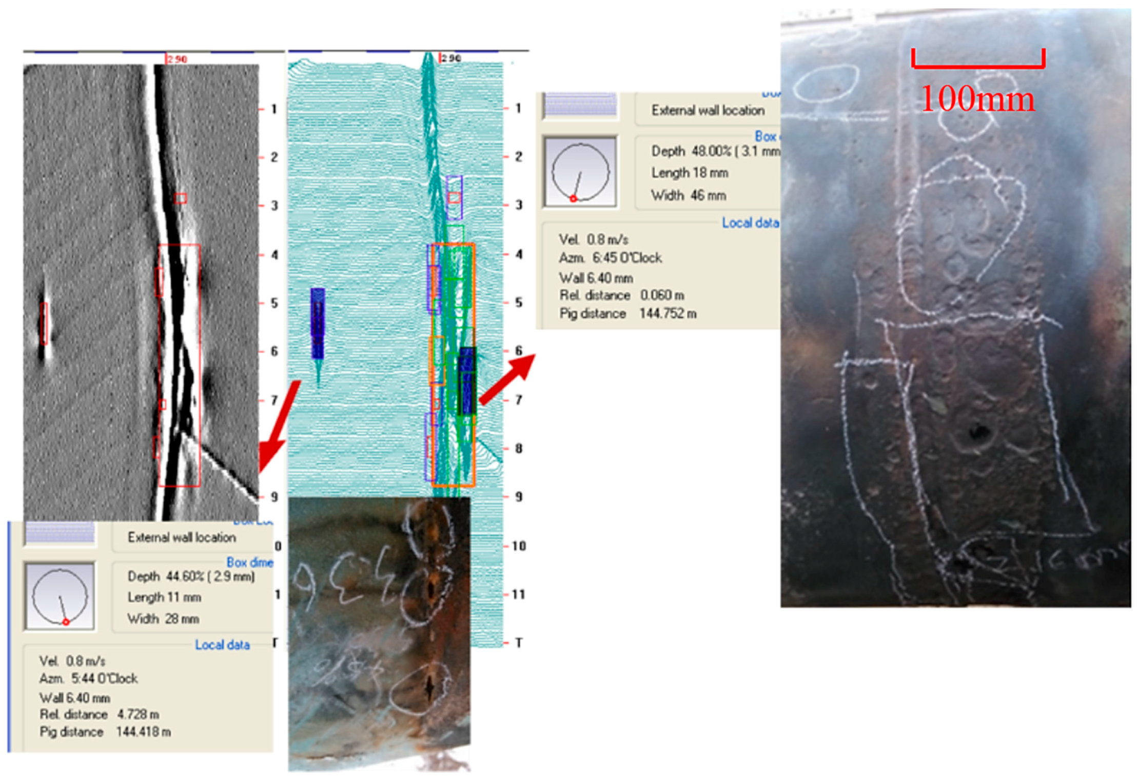
Type 2: Defects cluster or only one defect is reported with relatively long circumferential length, shown in Figure 4. This type is with a certain possibility of FJC failure, which may be the just beginning of pipe corrosion however needs verifications.
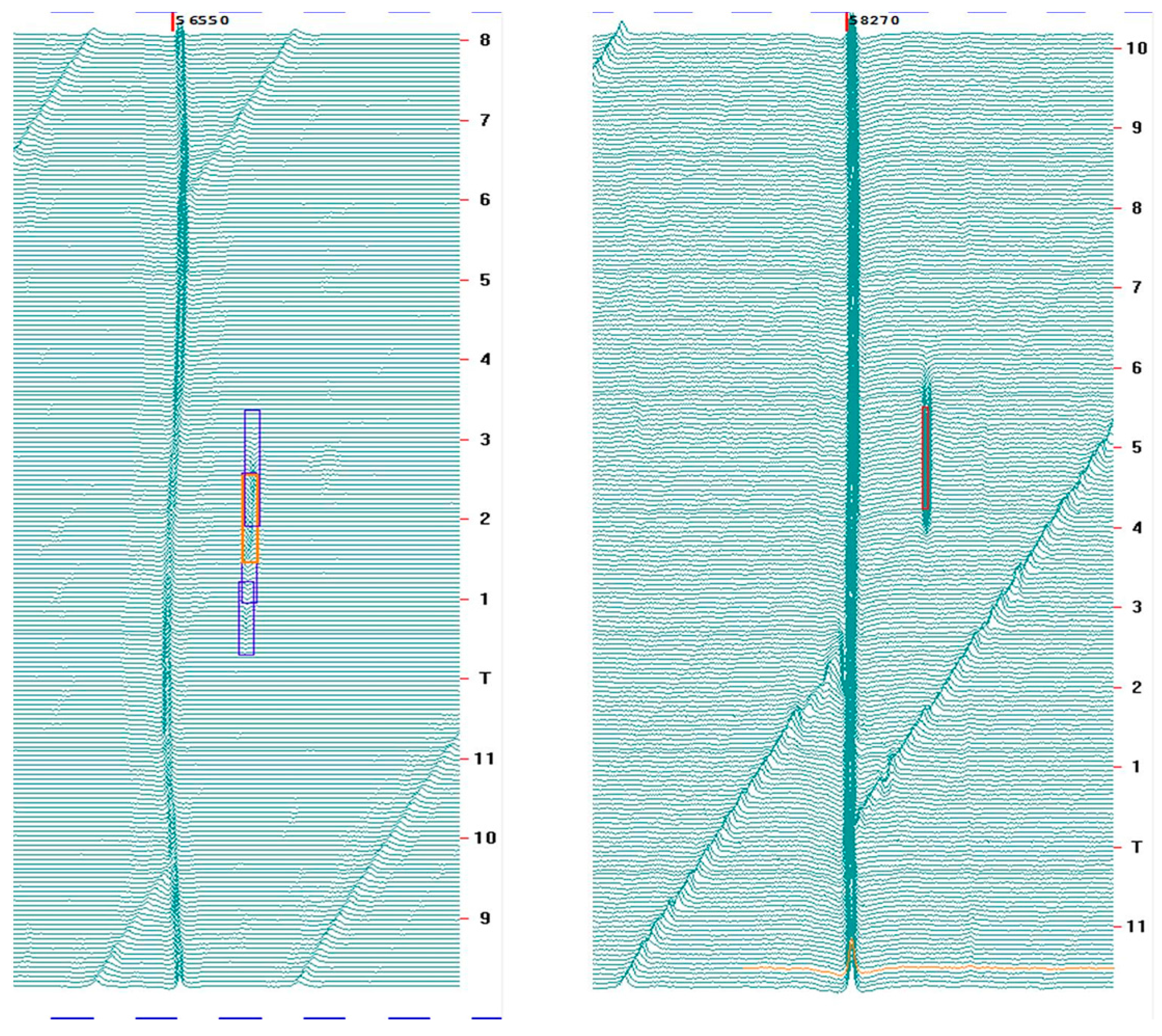
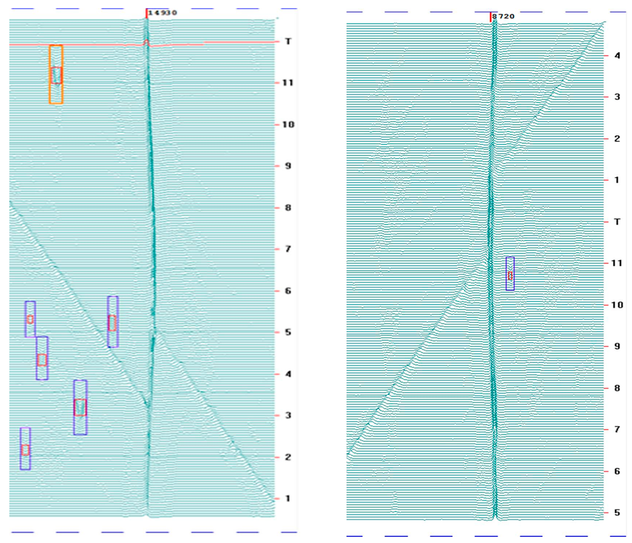
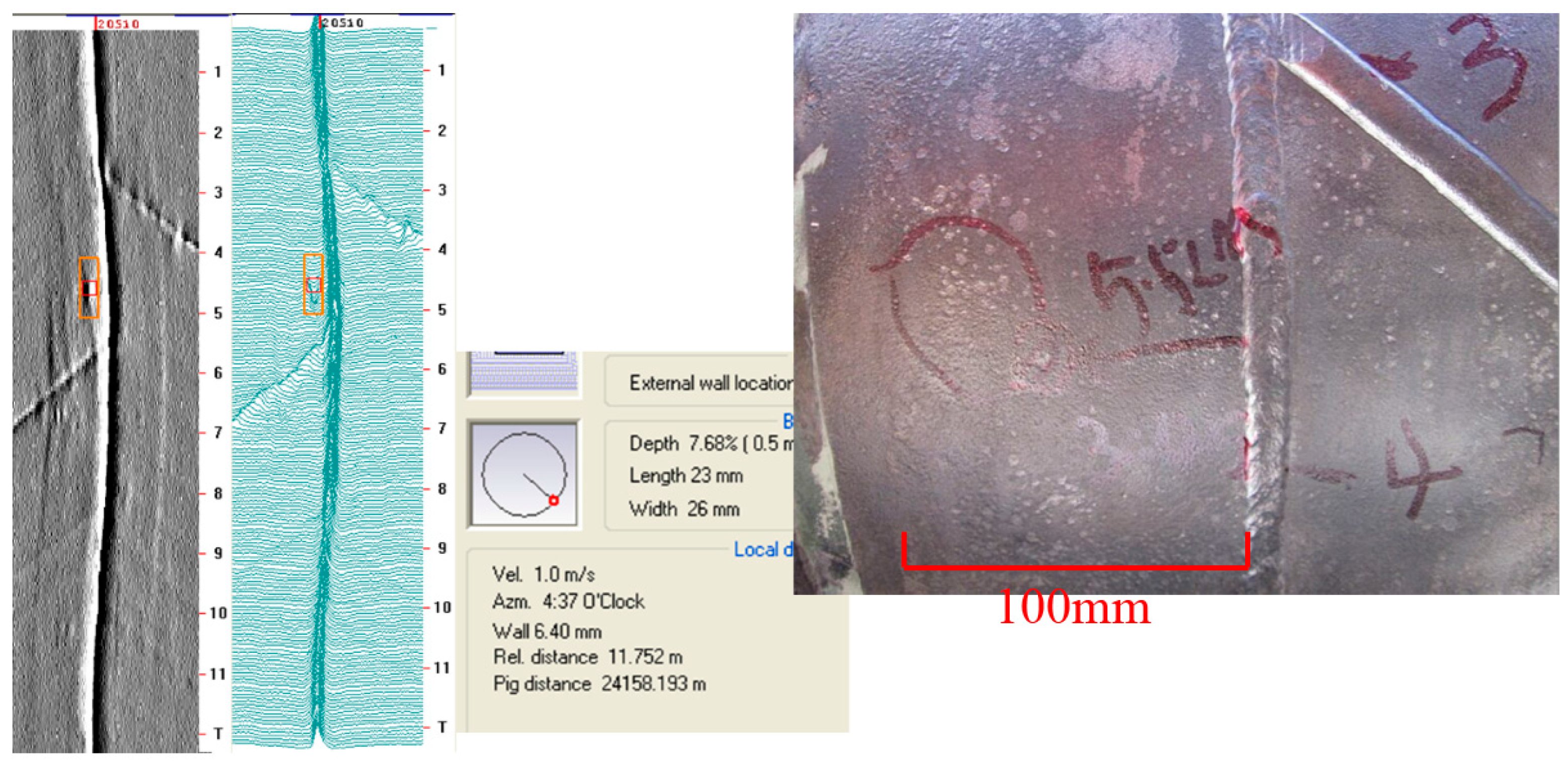
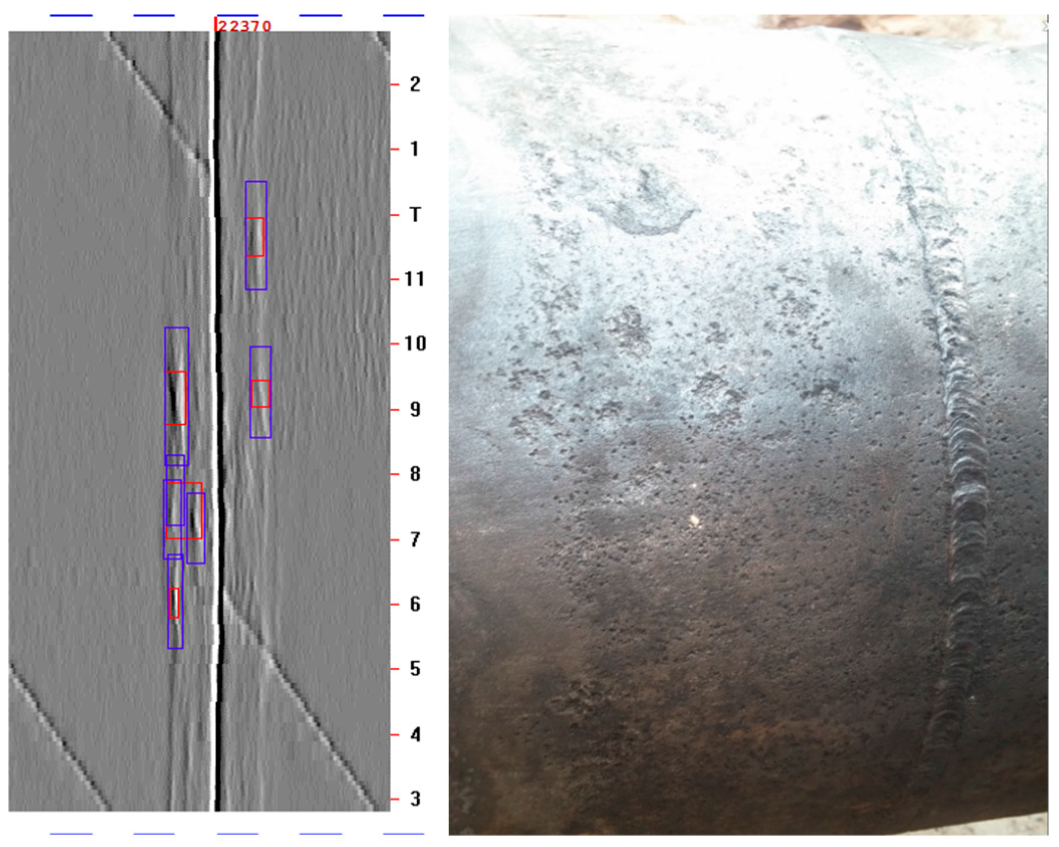
Type 3: Defects are dispersed or single, and all with small sizes, as shown in Figure 5. Though there are metal loss defects that are reported in the field joint zone, these may be manufactured defects that are difficult to be distinguished from corrosion and are possibly not caused by the FJC failures.
In order to establish the identification rule of FJC failures, altogether, 414 excavations were conducted to set up the relation between features in MFL ILI signals and types of real FJC failures.
414 excavations belong to two different pipeline sections which have been inspected by MFL recently. One is full of groundwater with numbers of river crossings, while the other is relatively dry with seasonal groundwater, in order to investigate the effect. Excavations of two sections with different types are listed in Table 1.
3. Excavation Results
Results are shown in Table 2.
Nearly half of the excavations (42.0%) showed that the FJCs were in good conditions and no defects found, while the metal loss signals shall be caused by the grinding before spraying anticorrosive primer in the field usually with reported depths below 5 wt %, or manufactured defects. Typical signal and excavation picture are shown in Figure 6 and Figure 7. MFL signals are not able to tell and discriminate them from corrosions very well until now. However, there are still some differences in features between them, such as the signal edges of manufacturing defects are more clear and sharp. There is another way to tell if it is corrosion: for gray-scale signals, there are always riverside pattern lines appearing in the FJC regions when corrosion occurs. See Figure 8.
As for these two kinds of sections, the percentage of intact FJCs for relatively dry section (55.1%) is higher than that of section (30.1%) with numbers of river crossings.
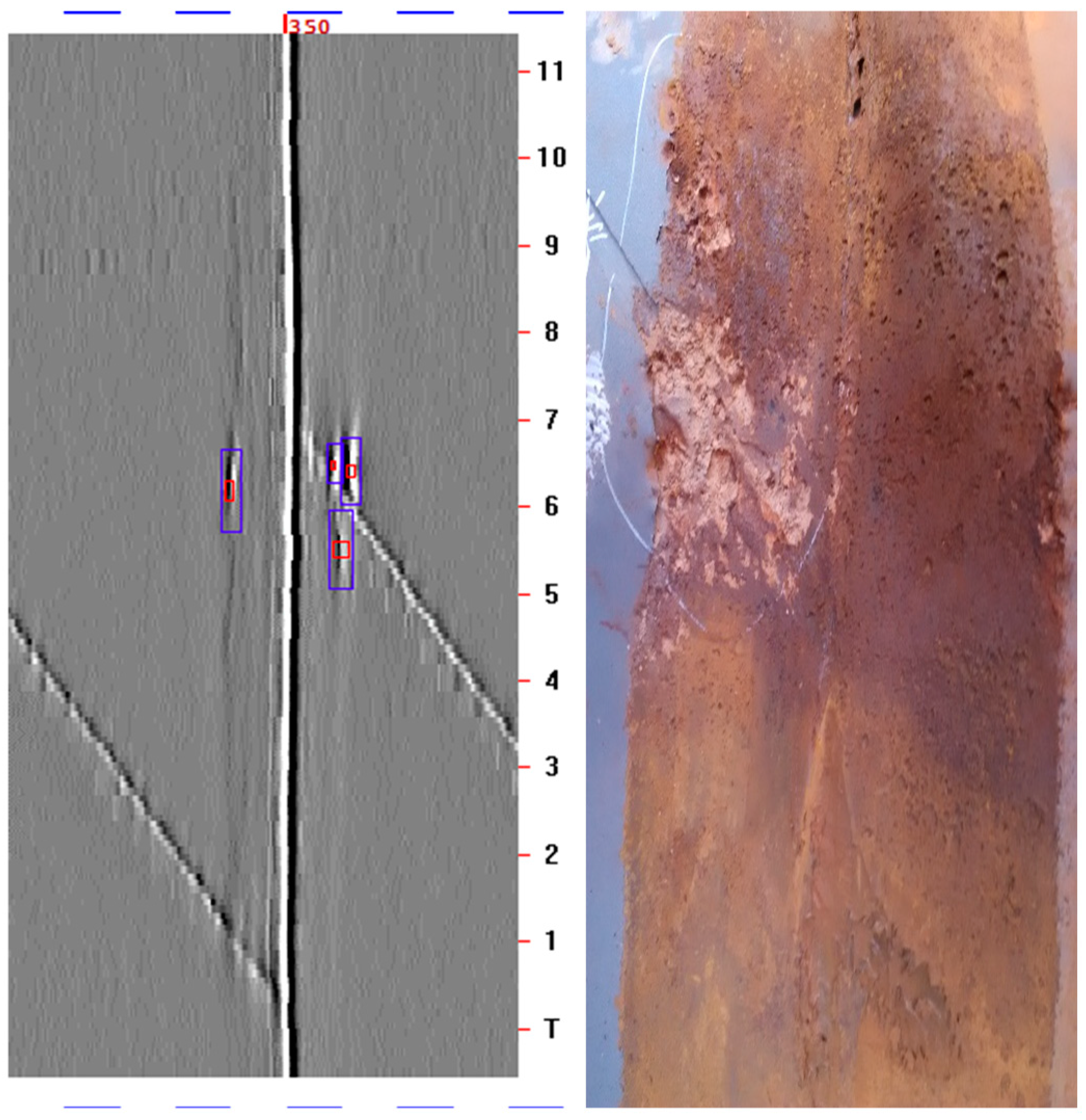
More than half of the excavations (58.0%) showed that the FJCs were failed and the reported defects were corrosions. Though it may not be always true, the patchy like corrosions caused by FJC failures usually distributed in the bottom or near the bottom of the pipe, that is, 4 o’clock to 8 o’clock in orientation. Typical signals and excavation pictures are shown in Figure 9 and Figure 10, usually with reported depths above 10 wt %. As for these two kinds of sections, percentage of corrosions for relatively dry section (44.9%) is lower than that of section (69.9%) with numbers of river crossings.
4. Rules of Failed FJC Identification
According to the investigation results, the rules of failed FJC identification has been established.
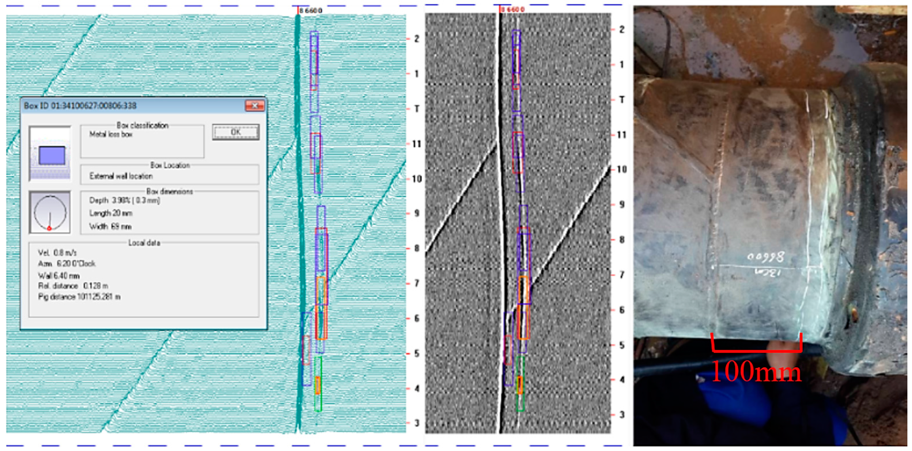
Type 1: Defects cluster in patches or strips, or one single corrosion depth is more than 30 wt %. This type is the most likely failed FJCs. Typical picture is shown in Figure 11.
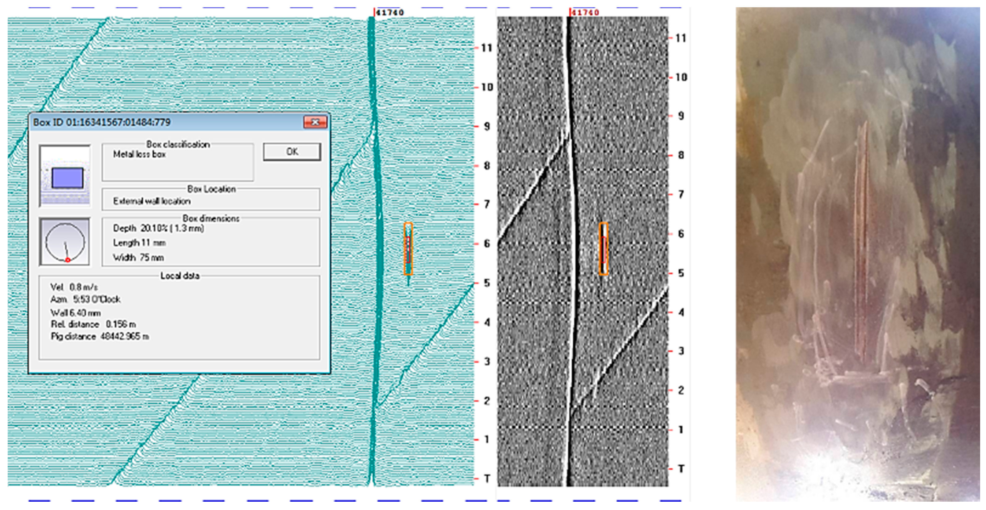
Type 2: Circumferential length of defect (signal or combined) is above 40 mm with depth above 5 wt %. Typical picture is shown in Figure 12.
Type 3: Defects are dispersed, but there are riverside pattern lines appearing in the FJC regions of gray-scale signals with at least one defect’s depth above 5 wt %. Typical picture is shown in Figure 13.
This rule has been verified on another 148 FJCs from several pipelines’ repair work, with accuracy of 90.5% (134 excavations were failed FJCs).
5. Conclusions
Through ILI tools can detect pipe body’s condition directly, it is definitely an indirect way to identify FJC failure. That is to say, until the failed FJCs cause external corrosions, they can be found with a certain accuracy by checking the ILI signals; while, for those failed FJCs without any corrosion indications, they cannot be found effectively. However, this method is much more efficient and cost-saving; at least the more serious failures that already cause damage on pipe will not be missed.
Rules are established specifically according to the 414 excavations, and be verified by another 148 excavations with accuracy of 90.5%. However, more validations and improvements are needed to make it more applicable and accurate.
Acknowledgments
The authors are grateful to the PetroChina Pipeline Company for financial support and the PetroChina Pipeline R&D Center for technical support, and declare that there is no conflict of interest regarding the publication of this paper.
Author Contributions
Lianshuang Dai and Ting Wang conceived and designed the researches; Qingshan Feng performed the excavations; Lianshuang Dai, Caiyan Deng and Dongpo Wang analyzed the MFL data; Lianshuang Dai and Ting Wang wrote the paper.
Conflicts of Interest
The authors declare no conflict of interest.
References
- Hopkins, P. Transmission pipelines: How to improve their integrity and prevent failures. In Pipeline Technology, Proceedings of the 2nd International Pipeline Technology Conference, Ostend, Belgium, 11–14 September 1995; Denys, R., Ed.; Elsevier: Amsterdam, The Netherlands, 1995; Volume 1, pp. 683–706. [Google Scholar]
- Zheng, W.Y. Stress corrosion cracking of oil and gas pipelines in near neutral pH environment: Review of recent research. Energy Mater. Mater. Sci. Eng. Energy Syst. 2008, 3, 220–226. [Google Scholar] [CrossRef]
- Guidetti, G.P.; Rigosi, G.L.; Marzola, R. The use of polypropylene in pipeline coatings. Prog. Org. Coat. 1996, 27, 79–85. [Google Scholar] [CrossRef]
- Romano, M.; Dabiri, M.; Kehr, A. The Ins and Outs of Pipeline Coatings: Coatings Used to Protect Oil and Gas Pipelines. J. Prot. Coat. Linings 2005, 22, 40–47. [Google Scholar]
- Chang, B.T.A.; Mitschke, H.R. Selection of Field Applied Liquid Rehabilitation Pipeline Coatings. Corros. Rev. 2011, 21, 27–39. [Google Scholar] [CrossRef]
- Singh, R. Pipeline Integrity Handbook: Risk Management and Evaluation; Gulf Professional Publishing: Oxford, UK, 2014; p. 51. [Google Scholar]
- Smith, F.H. Field joint coating of pipelines—Effect of soluble salt contamination on 2-layer heat shrink sleeve performance. Anti-Corros. Methods Mater. 2016, 63, 105–115. [Google Scholar] [CrossRef]
- Liu, Y.; Li, C.; Li, L. Solution to the defects in 3LPE field coating for welded joints of pipelines. Nat. Gas Ind. 2015, 35, 99–101. [Google Scholar]
- Jiang, Y.; Liu, M.; Zhang, W.; Lan, W.; Gai, J.; Ren, A.; Jiang, Y. Corrosion Survey for Field Joints of Long-distance Thermal Insulated Pipeline. Corros. Sci. Prot. Technol. 2017, 29, 323–327. [Google Scholar]
- Malik, A.U.; Andijani, I.; Ahmed, S.; Al-Muaili, F. Corrosion and mechanical behavior of fusion bonded epoxy (FBE) in aqueous media. Desalination 2002, 150, 247–254. [Google Scholar] [CrossRef]
- Jadoon, A.N.K.; Thompson, I. Fusion bonded epoxy mainline and field joint coatings performance from the X100 field trial—A case study. Int. J. Press. Vessels Pip. 2012, 92, 48–55. [Google Scholar] [CrossRef]
- Papavinasam, S.; Attard, M.; Revie, R.W. External polymeric pipeline coating failure modes. Xosé Manuel Cid Fernández 2006, 1, 495–505. [Google Scholar]
- Ruschau, G.; Chen, Y. Determining the CP Shielding Behavior of Pipeline Coatings in the Laboratory. In Proceedings of the CORROSION 2006, San Diego, CA, USA, 12–16 March 2004; NACE International: Houston, TX, USA, 2006. [Google Scholar]
- King, F.; Been, J.; Worthingham, R.; Rubie, G. Laboratory and Field Investigations of the Performance of HPCC Coatings. In Proceedings of the 2004 International Pipeline Conference, Calgary, AB, Canada, 4–8 October 2004; pp. 53–58. [Google Scholar]
- Greig, A.; Grillenberger, J. Identification of repair coatings on pipelines using in-line inspection technologies. In Proceedings of the 2016 11th International Pipeline Conference, Calgary, AB, Canada, 26–30 September 2016. [Google Scholar]
- Fisher, J.L.; Shukla, P.K. Detection of Coating Defects on Buried Pipelines Using Magnetic Field Variations within the Pipeline. U.S. Patent No. 9,638,667, 2 May 2017. [Google Scholar]
- Caleyo, E.; Alfonso, L.; Hallen, J.M. Method proposed for calibrating MFL, UT ILI tools. Oil Gas J. 2004, 102, 76–86. [Google Scholar]
- Tiratso, J. Pipeline Pigging & Integrity Technology; Clarion Technocal Publisher: Houston, TX, USA, 2003. [Google Scholar]
- Carvalho, A.A.; Rebello, J.M.A.; Sagrilo, L.V.S.; Camerini, C.S.; Miranda, I.V.J. MFL signals and artificial neural networks applied to detection and classification of pipe weld defects. NDT E Int. 2006, 39, 661–667. [Google Scholar] [CrossRef]
- Park, G.S.; Sang, H.P. Analysis of the velocity-induced eddy current in MFL type NDT. IEEE Trans. Magn. 2004, 40, 663–666. [Google Scholar] [CrossRef]
- Zhang, Y.; Ye, Z.; Xu, X. An adaptive method for channel equalization in MFL inspection. NDT E Int. 2007, 40, 127–139. [Google Scholar] [CrossRef]
Figure 1.
Field joint coating (FJC) failure and cause the pipe body corrosion.
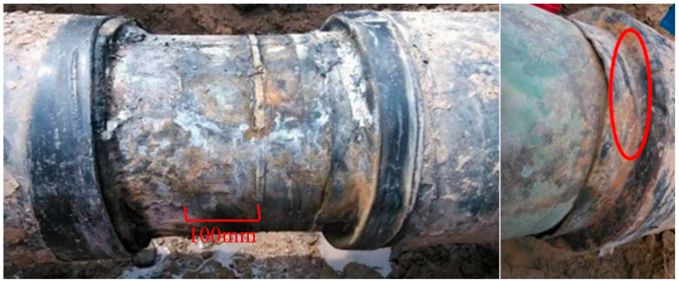
Figure 2.
The magnetic flux leakage principle.
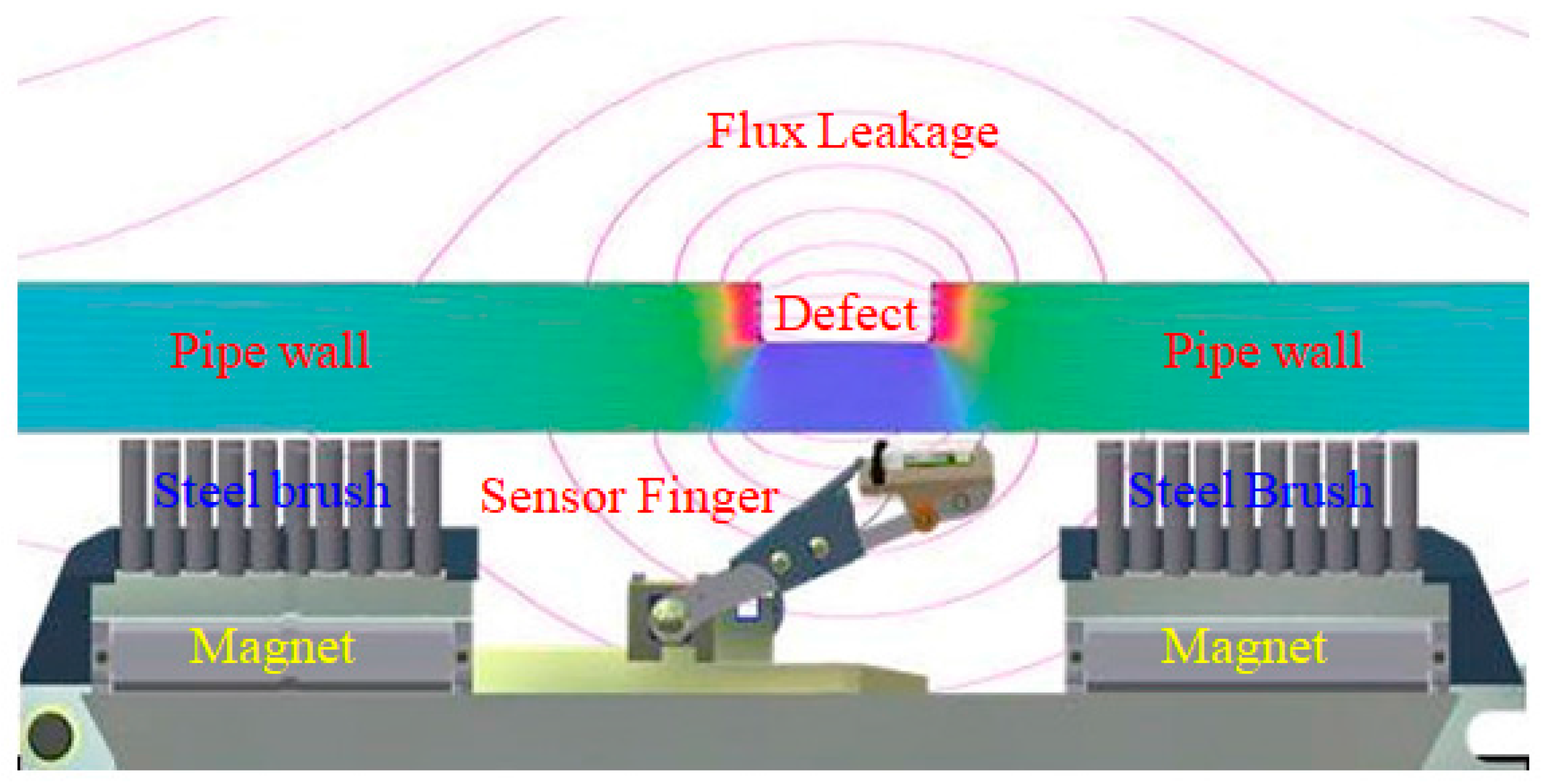
Figure 3.
Type 1 magnetic flux leakage (MFL) signals.
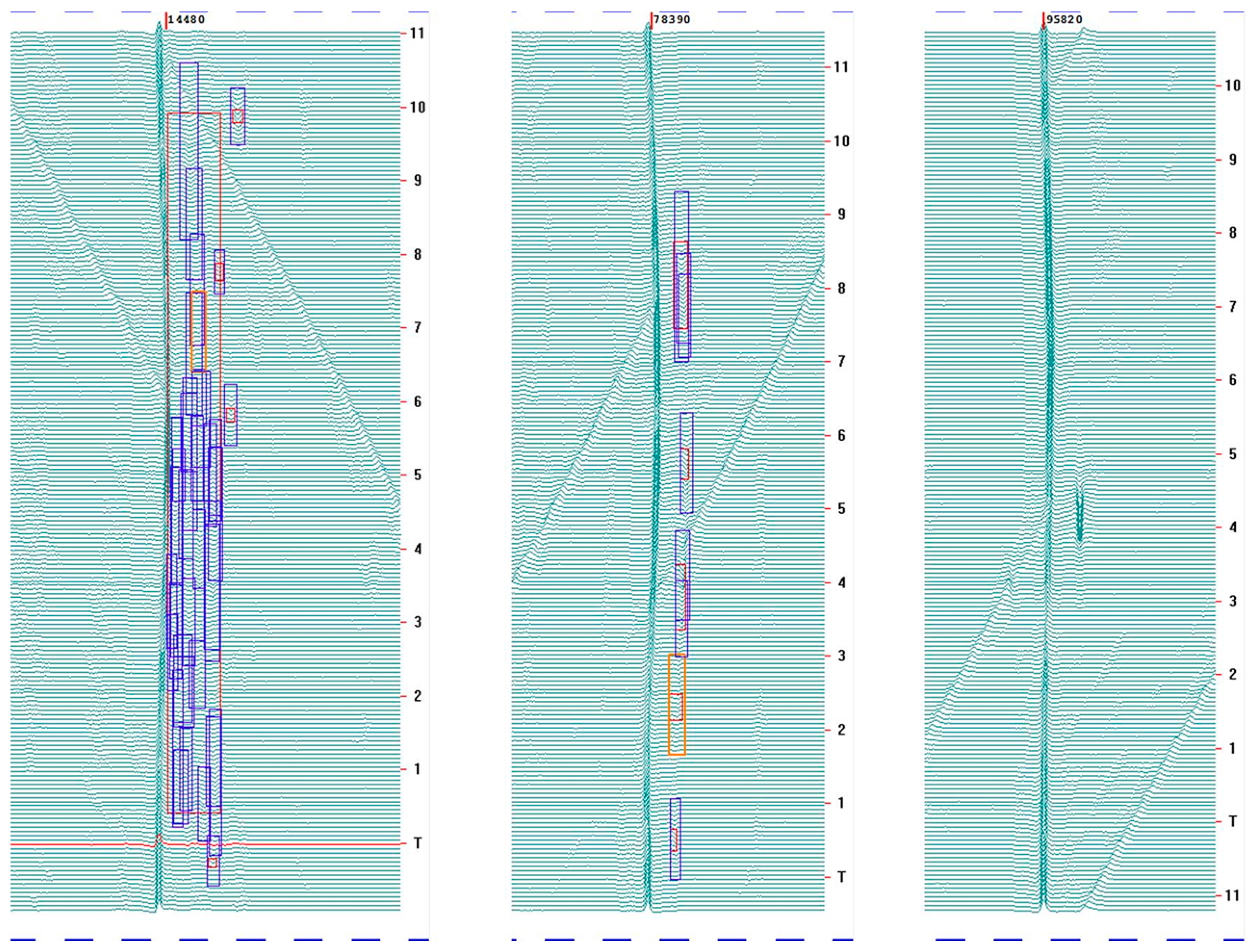
Figure 4.
Type 2 MFL signals.

Figure 5.
Type 3 MFL signals.

Figure 6.
The metal loss signals caused by the grinding.

Figure 7.
The metal loss signals caused by the manufacturing.

Figure 8.
The corrosion signals and picture with riverside pattern.

Figure 9.
Typical signals and excavation pictures for corrosion.

Figure 10.
Typical MFL gray-scale signals for FJC failure corrosion.
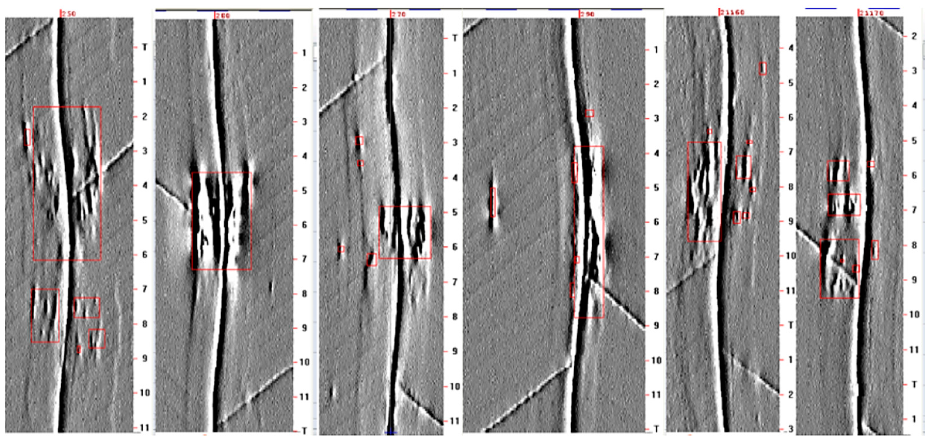
Figure 11.
Typical signals and excavation pictures for type 1. (a) Excavation results of defect with peak depth of 33.9 wt %; (b) Excavation results of defect with peak depth of 40.4 wt %.
Figure 11.
Typical signals and excavation pictures for type 1. (a) Excavation results of defect with peak depth of 33.9 wt %; (b) Excavation results of defect with peak depth of 40.4 wt %.

Figure 12.
Typical signals and excavation pictures for type 2.

Figure 13.
Typical signals and excavation pictures for type 3.


Table 1.
Excavations of two sections with different types.
| Sections | Subtotal | Type 1 | Type 2 | Type 3 |
|---|---|---|---|---|
| Section I (Relatively dry) | 198 | 47 | 118 | 33 |
| Section II (Numbers of river crossings) | 216 | 49 | 121 | 46 |
| Total | 414 | 96 | 239 | 79 |
| Percentage | 23.2% | 57.7% | 19.1% |
Table 2.
Excavation results of two sections for FJC failure numbers.
| Sections | Subtotal | Type 1 | Type 2 | Type 3 |
|---|---|---|---|---|
| Section I (Relatively dry) | 89 | 41 | 44 | 4 |
| Section II (Numbers of river crossings) | 151 | 47 | 86 | 18 |
| Total | 240 | 88 | 130 | 22 |
| Percentage | 36.7% | 54.1% | 9.2% |
© 2018 by the authors. Licensee MDPI, Basel, Switzerland. This article is an open access article distributed under the terms and conditions of the Creative Commons Attribution (CC BY) license (http://creativecommons.org/licenses/by/4.0/).
Share and Cite
MDPI and ACS Style
Dai, L.; Wang, T.; Deng, C.; Feng, Q.; Wang, D. New Method to Identify Field Joint Coating Failures Based on MFL In-Line Inspection Signals. Coatings 2018, 8, 86. https://doi.org/10.3390/coatings8030086
AMA Style
Dai L, Wang T, Deng C, Feng Q, Wang D. New Method to Identify Field Joint Coating Failures Based on MFL In-Line Inspection Signals. Coatings. 2018; 8(3):86. https://doi.org/10.3390/coatings8030086
Chicago/Turabian StyleDai, Lianshuang, Ting Wang, Caiyan Deng, Qingshan Feng, and Dongpo Wang. 2018. "New Method to Identify Field Joint Coating Failures Based on MFL In-Line Inspection Signals" Coatings 8, no. 3: 86. https://doi.org/10.3390/coatings8030086
Note that from the first issue of 2016, this journal uses article numbers instead of page numbers. See further details here.