Theoretical Study on the Influence of Hard Coating on Vibration Characteristics of Fiber-Reinforced Composite Thin Shell


School of Mechanical Engineering & Automation, Northeastern University, Shenyang 110819, China
*
Author to whom correspondence should be addressed.
Coatings 2018, 8(3), 87; https://doi.org/10.3390/coatings8030087
Submission received: 14 January 2018
/
Revised: 13 February 2018
/
Accepted: 23 February 2018
/
Published: 27 February 2018
Abstract
:The influence of hard coating on vibration characteristics of fiber-reinforced composite thin shell (FCTS) is investigated theoretically. The theoretical model of the hard coating FCTS is firstly established by using the classical laminated shell theory, Love’s first approximation theory, Rayleigh-Ritz method, and strain energy method. The values of the natural frequency, modal shape, resonant response, and modal loss factor of the hard-coating shell are obtained, and the corresponding analysis procedure is also summarized. The verification of such a theoretical method is performed by a case study, and the analysis results show a good agreement between the presented method and finite element method. The main findings from this study include: (I) The natural frequencies of FCTS with hard coating firstly decrease and then increase with the increase of elastic modulus and loss factor of hard coating, and they also show an increasing tendency when the thickness of hard coating rises; (II) Increasing the values of elastic modulus, loss factor, and thickness of hard coating can help to reduce the vibration response of FCTS. However, with the increase of modal order of the composite shell, the reduction rates of resonant responses and the increased levels of modal loss factor will decrease.
1. Introduction
Due to the high strength to weight ratio and other superior performances, the fiber-reinforced composite thin shell has been increasingly used in a variety of engineering fields, such as composite casings in aircraft engines, pressure resistant composite shells in submarines, and high temperature resistant composite shells in rocket motor cases. As fiber-reinforced composite thin shell (FCTS) often works in complex environments, such as ones with vibration, noise, high pressure, and high-speed impact, some problems easily result such as high-level vibration amplitude, fatigue failure, fiber delamination, destructive damage, etc., which could lead to some disastrous accidents [1,2,3,4]. Therefore, it is of great scientific significance to study how to reduce the vibration of FCTS.
The hard coating is a kind of coating material manufactured using metals, ceramics, and mixtures, which is used as a surface treatment for anti-friction, anti-erosion, vibration reduction, and other engineering application fields [5,6,7,8]. In recent years, due to continuously reduced costs and more mature technologies, it has drawn increasing academic and engineering attention. If the hard coating material can be deposited on the surface of FCTS, then, through the internal frictions of coated particles and interface frictions of the coating and FCTS, the vibration energy of such composite shell structures can be transformed into heat energy, and the goal of reducing vibration of FCTS can be achieved.
At present, great efforts have been made to study vibration characteristics of thin-walled structures with hard coating, such as beams, plates, and shells, including the corresponding modeling and analysis techniques, vibration reduction design, evaluation methods, etc. For example, Green and Patsias [9] proposed a friction model to calculate the response of a coated beam, and the variation of damping effectiveness for several vibration modes and a range of amplitudes were calculated. The results showed this model can capture the behaviors of the test piece well, after comparing with experimental results. Patsias et al. [10] developed an experimental procedure that could accurately control the vibration amplitude, excitation frequency, and temperature so as to extract the damping parameter and elastic modulus of hard coating. Masti and Sainsbury [11] established the corresponding formulas with finite element method and adaptive shell elements to study the vibration damping characteristics of the cylindrical shell that was partially deposited with viscoelastic coating. Ivancic, Blackwell and Palazotto [12,13] measured the natural characteristics of a titanium plate coated with magnesium aluminate spinel. They found that compared with the uncoated specimen, the frequency response of the hard coating composite plate was not symmetric about the resonance frequency, and the resonance frequency decreased with the increase of the applied force amplitude, which indicated the nonlinear stiffness characteristics, also called the “strain softening”. Sofiyev and Kuruoglu [14,15] conducted numerical analysis of torsional vibration and bucking of cylindrical and conical shells with functionally graded (FG) coating resting on Pasternak elastic foundations, and the basic equations were derived by Donnell’s theory and solved by the Galerkin method. Song et al. [16] presented a strategy to solve the high-order vibration of the rotating thin shell based on the transfer matrix method, and the damping effects of hard coating on the natural characteristics were illustrated. Zhang and Li [17] presented an analysis procedure, where the generalized differential quadrature (GDQ) method was applied to investigate the free vibration of the functionally graded conical shells with a variety of boundary conditions. Najafov et al. [18] investigated the effect of thickness and material composition of the functionally graded coatings on the frequency-amplitude relationships of a truncated conical shell. Chen et al. [19] analyzed the damping effect of the hard coating on the blades based on the constitutive model of the complex modulus. Dey and Mukhopadhyay et al. [20] used a surrogate model (D-optimal design) approach to study the stochastic natural frequencies of laminated composite conical shells. The effects of twist angle, ply orientation, and material properties on the uncertainty quantification of the natural frequency was also considered. Sun et al. [21,22] considered the elastic constraints and the strain dependence to analyze the free vibration behavior of hard coating cylindrical metal shell and beam structures using the Rayleigh-Ritz method, and the correctness of the created models were verified by the comparison between the calculation and experiment. Naskar and Mukhopadhyay et al. [23] presented a novel concept of stochastic representative volume element (SRVE) to study the natural frequencies of thin-walled laminated composite beams with spatially varying matrix cracking damage in a multi-scale framework through a stochastic approach. Zhang et al. [24] proposed a four-node composite cylindrical shell model to solve the nonlinear vibration problems efficiently by combining the Love’s first approximation theory with finite element method, and the influence of the strain dependence of the coating material on the complex stiffness matrix was considered.
From the above literature reviews, it is clear that the vibration modeling techniques are still rare for fiber-reinforced composite shell structures coated with hard coating material, and the influences of hard coating on vibration characteristics of FCTS are not well researched. Therefore, this research tries to establish an appropriate theoretical model to study the influence of the elastic modulus, loss factor, and thickness of hard coating on the vibration characteristics of the composite shell. The paper is organized as follows. Firstly, the theoretical model of the hard coating FCTS is established by using Hamilton’s principle in conjunction with the classical laminated shell theory, Love’s first approximation theory, the Rayleigh-Ritz method, and strain energy method; the natural frequencies, modal shapes, vibration responses, and modal loss factors of the hard coating composite shell can be obtained in Section 2. Then, the corresponding analysis procedure is summarized in Section 3, and a case study is carried out to verify the developed theoretical model in Section 4. Finally, in Section 5, the influence of hard coating parameters on the vibration behavior of the composite shell is discussed and some conclusions are drawn in Section 6. This research can provide a dynamic modeling service for FCTS with hard coating and also provide an important reference for vibration reduction design of hard coating applied on the composite shell structures.
2. The Modelling and Analysis of Vibration Characteristics of FCTS with Hard Coating
In this section, a new theoretical model of the hard coating FCTS is presented by the classical laminated shell theory, Love’s first approximation theory, the Rayleigh-Ritz method, and strain energy method; the corresponding analysis and solution is explained in detail.
2.1. The Theoretical Model of the Hard Coating FCTS
It is assumed that the FCTS is made of fiber and matrix material with n layers, and its upper surface is covered with hard coating material. The coating is very thin compared with the substrate shell, and the hard coating FCTS is under a cantilever boundary, as shown in Figure 1. Firstly, the curvilinear coordinates system o-xθz is used to establish the theoretical model, where the origin of the coordinate system is located on the neutral surface of the composite thin shell, x and θ are the longitudinal and circumferential direction, respectively, z is the radial direction, β is the angle between the fiber direction and the x axis, and u, v, and w are the displacement of any point on the middle surface in the x, θ and z directions. Then, the length, radius, and total thickness of the hard coating FCTS can be expressed as L, R and h, respectively, the density of the fiber-reinforced composite is ρf, the density of hard coating is ρc, the thickness of the fiber-reinforced composite layer of the shell is hs, and the thickness of the outside coating is hc (so the total thickness of the whole structure becomes hc + hs).
In this theoretical model, “1” refers to the direction parallel to fiber orientation, “2” refers to the direction perpendicular to fiber orientation (also known as fiber transverse orientation). λ(t) is the base excitation applied on the shell, and w(x, θ, t) is the vibration displacement in any response point Rc(x1, θ1, z1), as shown in Figure 1. If the hard coating is regarded as a specific layer of the shell, the coordinate of thickness direction of each layer can be represented by h1, h2, …, hk, hN, hN+1 (k = 1, 2, …, N, N + 1) from the lower surface to upper surface. In addition, N is the number of total layers including hard coating, while N-1 is the number of fiber-reinforced layers.
For each layer of composite thin shell, the stress-strain relations for the layers of the composite thin shell can be expressed as
where σ1, σ2 and ε1, ε2 are the stresses and strains in the “1” and “2” orientations, respectively; σ12 and γ12 are shear stress and shear strain, respectively, in the direction perpendicular to the 1-2 surface.
For an orthotropic material, the reduced stiffness can be defined as
where and are the complex elastic moduli in the “1” and “2” directions, is the complex shear modulus in the 1-2 surface, and and are Poisson’s ratios in the two directions.
The stress-strain relationship of the kth layer of composite thin shell in the global coordinates can be calculated by using a stress-strain transformation equation, which has the following form
where
where βk represents the angular orientation of fibers. σx, σθ, σxθ, εx, εθ, and γxθ are stresses and strains in the x-θ plane of the kth layer, respectively.
Since the isotropic hard coating is covered on the outside surface of the shell, the can be given by
where and refer to the complex elastic modulus and Poisson’s ratio of the hard coating.
The stress and strain vectors can be defined as follows:
The complex elastic moduli in Equations (2) and (5) can be expressed as
where , , , and represent the real part of , , , and , respectively. , , are the loss factors in the aforementioned three directions and is the loss factor of the hard coating.
The strain components in the strain vector from Equations (3) and (7) can be defined as the linear functions based on Love’s first approximation theory, and the relationship between the strain and displacement can be written as
where , , and are the reference surface curvatures, which can be written as follows
When considering the effect of fiber-reinforced composite, the internal force , , and internal moment , , of the shell can be defined as
By substituting Equations (3) and (8) into Equation (11), the constitutive equation can be obtained
where N, ξ, and S are the generalized force vector, strain vector, and stiffness matrix, respectively, which can be defined as
where , , and are the extensional, coupling, and bending stiffness (i, j = 1, 2, 6), which can be defined as
The total strain energy U of FCTS with hard coating can be written as
By substituting Equations (3) and (8) into Equation (17), the strain energy of fiber-reinforced composite and the strain energy of hard coating can be written as
By substituting Equations (18) and (19) into Equation (17) the total strain energy U can be written as
Because the composite thin shell is made up of two kinds of materials, the kinetic energy stored in FCTS can be expressed as
where is the density in the different layers of the shell.
2.2. Solution to the Natural Vibration
Assuming that the displacement of FCTS can be expressed as the function of the beam, which has the following forms
where A, B, and C are the constants denoting the amplitudes of the vibration in the x, θ, and z directions, n refers to the number of circumferential waves, ω represents angular frequency of vibration, and the axial modal function can be written as
where m refers to the number of axial waves. Because the studied shell with hard coating is under a cantilever boundary condition, by referring to the formulas used in the literature [25], λm, σm and ci (i = 1,2,3,4) are given as follows
where λm and σm can be expressed as λ1 = 1.8751, σ1 = 0.734096, λ2 = 4.69409, σ2 = 1.018467, λ2 = 7.85476 and σ3 = 0.999224.
Furthermore, the Lagrangian function of the FCTS with hard coatings can be obtained by substituting Equation (22) into Equations (20) and (21), respectively.
By applying the Rayleigh-Ritz procedure to the Lagrangian function, we can obtain
Which leads to the eigenvalue equation as follows
where is natural circular frequency in the rth mode of FCTS, and are the complex stiffness matrix and mass matrix, respectively, X is the eigenvector consisting of A, B, and C, and X can be expressed as
Thus, the stiffness matrix of the system is complex, and it can be expressed as , where and are the real and imaginary part of the stiffness matrix, respectively.
A set of eigenvalue equations can be obtained to solve the natural frequencies and modal shapes of FCTS.
By setting the determinant of Equation (28) to zero, the rth natural frequency can be obtained. Then, the vector X can be derived by substituting the into Equation (28). Finally, the corresponding modal shape in the rth modal order can be consequently obtained by substituting X into Equation (22). All concerned natural frequencies and modal shapes can be obtained by repeating these aforementioned steps.
2.3. Solution to the Vibration Response and Damping
Because the FCTS with hard coating is subjected to the base excitation , it can be expressed as
where is the amplitude of base excitation and is excitation circular frequency.
The total displacement along the z direction of the FCTS with hard coating can be expressed as
The strain energy of FCTS with hard coating remains unchanged when it is subjected to the base excitation, since it is merely related to the displacement . Thus, the modified kinetic energy under base excitation can be written as
By substituting Equations (20) and (31) into Lagrange’s equation described in Equation (24), the forced vibration equation of the FCTS with hard coating under the base excitation can be obtained with
where is the external force vector which is produced by the base excitation.
By solving Equation (32), the eigenvector X can be obtained. Furthermore, substituting X into Equation (22), we can obtain the concerned displacement in the rth mode with
where is the amplitude parameter induced by the base excitation in the z direction of the shell.
In this way, the total displacement of the hard coating composite thin shell can be obtained by substituting Equation (33) into Equation (30). Finally, by referring to the modal loss factor solving formulas used in the literature, the modal loss factor of FCTS can be obtained by modal strain energy method
where is the rth modal loss factor of FCTS and is the eigenvector corresponding to the rth mode.
3. The Analysis Procedure of Vibration Characteristics of FCTS with Hard Coating
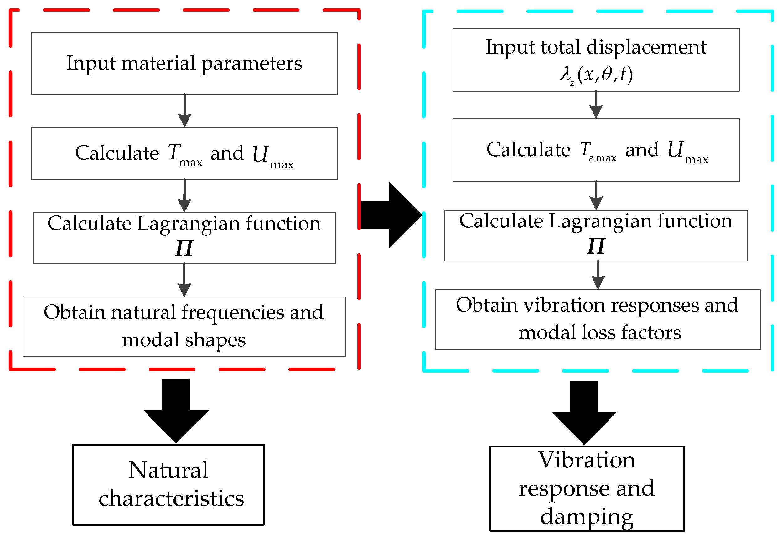
In this section, the analysis procedure of the natural frequency, vibration response, and modal loss factor of FCTS with hard coating is summarized objectively, which can be realized based on a self-designed matrix laboratory (MATLAB) program and can be divided into the following six key steps. The whole solution procedure of vibration characteristics of FCTS with hard coating is shown in Figure 2.
- (1)
- Establishing a theoretical model of FCTS with hard coating
In this step, we need to input the geometrical parameters such as the length, radius, thickness, and fiber angle of FCTS with hard coating. Consequently, the theoretical model can be established by the self-written MATLAB program with the parameters such as the elastic moduli, shear modulus, Poisson’s ratios, loss factors, and density.
- (2)
- Obtaining the maximum values of kinetic energy and strain energy of FCTS with hard coating
Firstly, according to the material properties of fiber reinforced composite and hard coating in each layer, the stress-strain relation formula of FCTS with hard coating can be derived, and the expression of extensional, coupling, and bending stiffness matrix of the composite shell can be solved. Then, by substituting the displacement function of Equation (22) into the equation of the kinetic energy and the strain energy, the expressions of the maximum kinetic energy and the maximum strain energy can be obtained, respectively.
- (3)
- Calculating the natural frequencies and the modal shapes
By substituting the modified maximum kinetic energy and the maximum strain energy into the Equation (24), the Lagrangian function of the FCTS with hard coatings can be obtained. Then, according to the Rayleigh-Ritz method in conjunction with Love’s first approximation theory, the eigenvalue equations, and Equation (26), the FCTS with hard coating can be obtained by calculating the derivatives of the undetermined parameters in Equation (22). At last, the natural frequencies and modal shapes can be calculated by solving the eigenvalues and eigenvectors.
- (4)
- Calculating the resonant responses under a certain amplitude of base excitation
By substituting the maximum kinetic energy and the maximum strain energy into the Lagrange’s equation, the eigenvalue equations under the base excitation can be obtained. Then, the displacement response vector X can be obtained by solving the eigenvalue equation. Finally, by setting the amplitude of base excitation and the position of the concerned response point in the theoretical model, the resonant responses in different modes of FCTS with hard coatings can be obtained by substituting Equation (33) into Equation (30).
- (5)
- Calculating the modal loss factors of FCTS
Based on these four steps mentioned above and also by referring to the solving formulas of modal loss factors, we can use the modal strain energy method to calculate the modal loss factors in different modes of the composite shell with hard coating.
4. A Case Study and Verification
A carbon/epoxy composite thin shell with NiCoCrAlY + YSZ hard coating is studied, and both the finite element method and the analytical method presented are employed to establish the corresponding theoretical models. There are 25 layers of FCTS with hard coating, where the upper layer is hard coating and the lower layers are fiber reinforced composite. Fiber-reinforced composite is symmetrically laid, which has a total of 24 layers with the laminate configuration of [(45°/−45°)12], and each layer has the same thickness and fiber volume fraction. The corresponding geometric and material properties of the FCTS and hard coating are listed in Table 1. The material property of the FCTS is listed in Table 2. And material property of hard coating is that = 54 GPa, = 0.0212, = 0.3, and ρc = 5600 kg/m3.
The finite element model of FCTS with hard coating is established with Ansys Parametric Design Language (APDL) in ANSYS software, as shown in Figure 3. The SHELL 181 element is used to create the model of the shell with hard coating, which consists of 15,300 nodes and 10,000 elements, and all the nodes along one side of the shell are constrained in all six degrees of freedom to represent the cantilever boundary condition. Then, the fiber orientation angles and thicknesses of FCTS with hard coating are considered by using the SECTION/SHELL command. Meanwhile, the damping of the hard coating is introduced into the model by using the DMORAT command, where the strain energy of hard coating and the strain energy of FCTS are represented by ENERGY1 and ENERGY that both can be extract by the ETABLE and GET commands, respectively. Next, the first eight natural frequencies and modal shapes of FCTS with hard coating are solved by the block Lanczos method, and the corresponding modal loss factors are calculated by the modal strain energy method. At last, the full method in the harmonic response analysis is chosen to solve the first eight resonant responses under the base excitation load, and the relevant results of frequencies, mode shapes, resonant responses, and modal loss factors are shown in Table 3, Table 4 and Table 5. For the convenience of comparison, the related results obtained by the analytical method are also listed in the same Tables. It should be noted that the base excitation amplitude of 6 g is applied on the theoretical model, and the coordinate of the response point is (0.75L, 1.75π, R). Meanwhile, the same base excitation amplitude is applied on the finite element model, and the closest node to the position (0.75L, 1.75π, R) is chosen to calculate the corresponding resonant response results, so as to verify the correctness of the present method.
It can be seen from the above results that the max calculation error of natural frequencies, resonant responses, and modal loss factors between the analytical method and finite element method are no more than 0.41%, 3.82%, and 4.84%, respectively, which is within the allowable range. Therefore, the practicability and reliability of the present method have been verified and the results can be used to analyze and predict the vibration characteristics of the FCTS with hard coating.
5. The Influences of Hard Coating on the Vibration Characteristics of FCTS
In this section, the influence of elastic modulus, loss factor, and thickness of hard coating on the vibration characteristics of FCTS is investigated.
5.1. The Influence of Elastic Modulus of Hard Coating
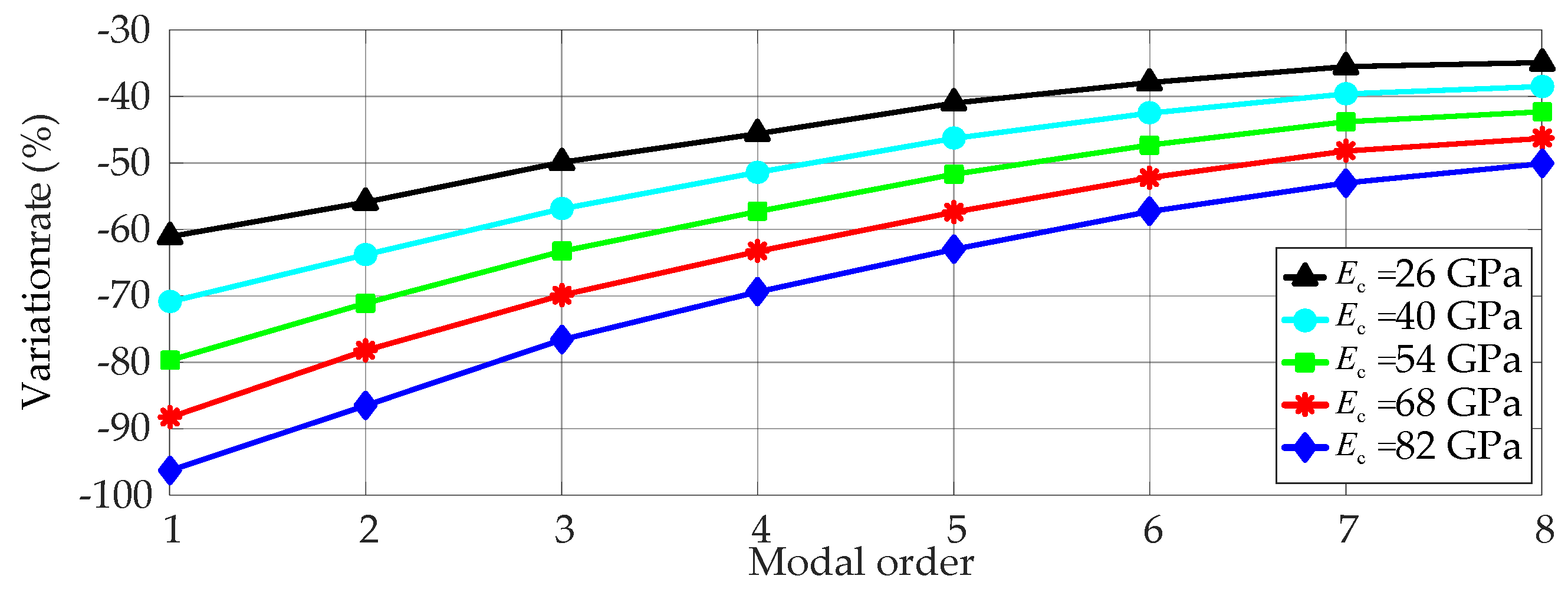
The elastic modulus of hard coating is set to be 26, 40, 54, 68, and 82 GPa, and other parameters of FCTS are set to be constants. The first eight natural frequencies, resonant responses, and modal loss factors of FCTS with hard coating are calculated and the relevant results are displayed in Table 6 and Table 7, Figure 4 and Figure 5. It should be noted that the same excitation amplitude of 6 g and the same response point (0.75L, 1.75π, R) in the theoretical model is used to calculate resonant responses under different elastic moduli of hard coating.
From the above results, it can be found that: (1) When the above elastic modulus values are selected, the natural frequencies of FCTS with hard coating decrease firstly before increasing with the increase of the elastic modulus of hard coating. The increased levels of natural frequencies become larger with the increase of modal order; (2) The resonant responses of FCTS with hard coating decrease with the increase of the elastic modulus of hard coating. Meanwhile it can be seen from Figure 4 that there are much more reduced rates in the corresponding resonant response results in the lower modes compared with response results in the higher modes, which means that the increase of the elastic modulus of hard coating has a better damping effect on the lower modes of FCTS with hard coating; (3) The modal loss factors of FCTS with hard coating increase with the increase of the elastic modulus of hard coating. However, the increased levels of the modal loss factor of FCTS with hard coating in the higher modes are smaller than the results of the lower modes.
5.2. The Influence of Loss Factor of Hard Coating
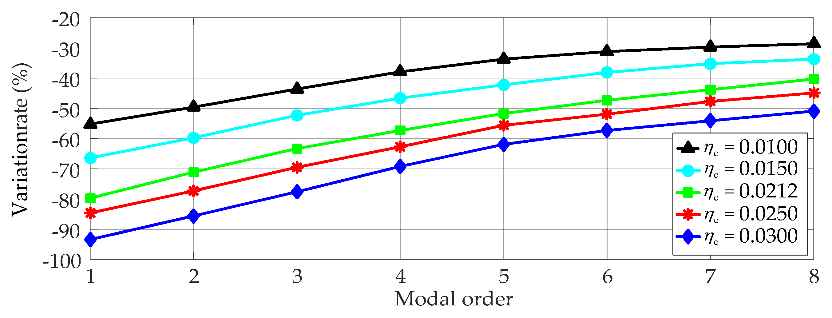
In this section, the loss factor of hard coating is chosen as 0.01, 0.015, 0.0212, 0.025, and 0.03, and other parameters of the FCTS are set to be constants. The Equation (28) shows that the natural frequencies of the FCTS with hard coating can be affected by the real part of the stiffness matrix and the mass matrix. However, the loss factor of hard coating has no influence on these two matrices, so it is not responsible for the change of natural frequencies of the composite shell. Besides, the imaginary part of the stiffness matrix can be affected by the loss factor of hard coating. Therefore, this coating material does have the damping effects on the resonant responses of the composite shell. Here, the first eight resonant responses and the modal loss factors corresponding to different loss factors of hard coating are calculated, and the relevant results are listed in Table 8, Figure 6 and Figure 7.
From the above results, it can be seen that: (1) The resonant responses of FCTS with hard coating decrease with the increase of the loss factors of hard coating. In the meantime, there are much more reducted rates in the corresponding response results of lower modes compared with response results in the higher modes. So, improving loss factors of hard coating has a better vibration reduction effect on the lower modes of FCTS with hard coating; (2) The modal loss factor of FCTS with hard coating increases with the increase of the loss factors of the hard coating, but the increased levels of modal loss factor become weaker with the increase of modal order of FCTS with hard coating.
5.3. The Influence of Thickness of Hard Coating
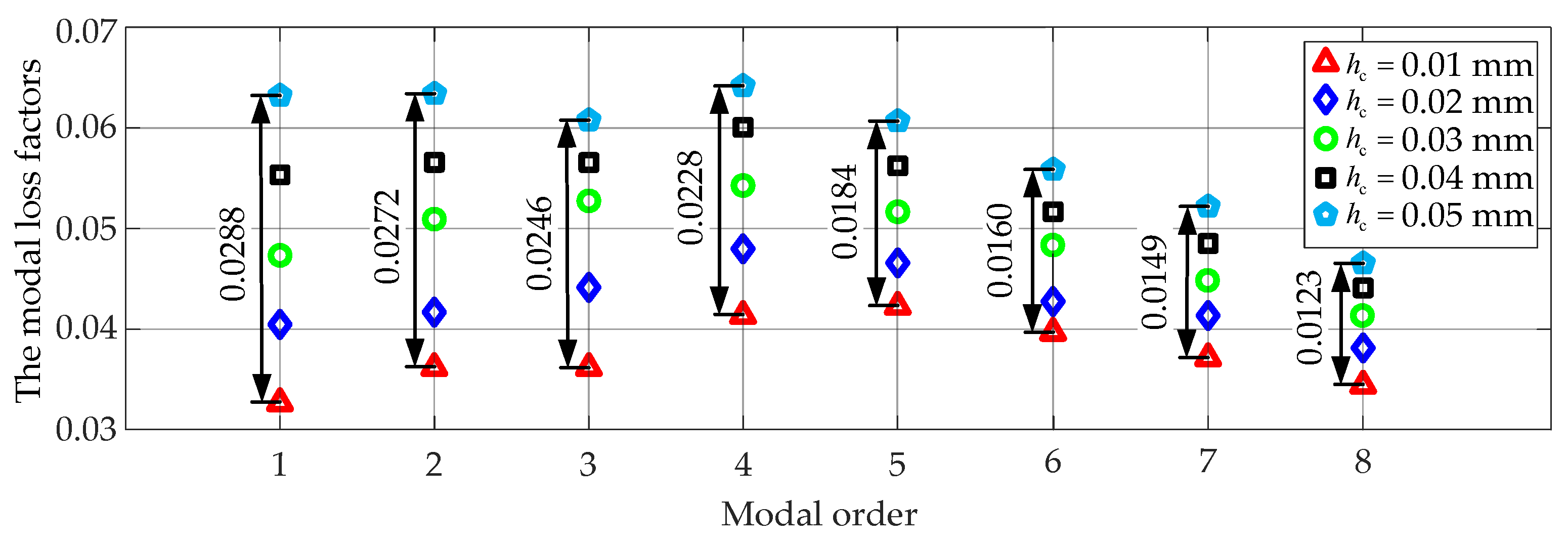
Finally, the hard coating thickness is set to be 0.01, 0.02, 0.03, 0.04, and 0.05 mm so as to study the effect of the thickness of hard coating on vibration characteristics when the other parameters of the FCTS are set to be constants. The first eight natural frequencies, resonant responses, and the modal loss factors of the FCTS with hard coating are calculated, and the relevant results are listed in Table 9 and Table 10, Figure 8 and Figure 9.
From the above results, it can be found out that: (1) The natural frequencies of FCTS with hard coating increase with increasing thickness of the hard coating, and the increased magnitude becomes larger with the increase of modal order; (2) The resonant responses of FCTS with hard coating decrease with the increase of the thickness of hard coating, and the reduction rates of resonant responses decrease with the increase of modal order. Therefore, the increase of the thickness of hard coating has a better vibration reduction effect on the lower modes of FCTS; (3) The modal loss factors of FCTS with hard coating increase with the increase of the thickness of hard coating, but the increased levels of modal loss factor become weaker with the increase of modal order.
6. Conclusions
This research has investigated the influence of hard coating on vibration characteristics of FCTS under the base excitation. The main findings from this study include:
- (1)
- The natural frequencies of FCTS with hard coating firstly decrease and then increase with increase of the elastic modulus and loss factor of hard coating. They also show an increasing tendency when the thickness of hard coating rises. Besides, the increased rates of natural frequencies become larger as the modal order increases.
- (2)
- The resonant responses of FCTS with hard coating decrease with the increase of the elastic modulus, loss factor, and thickness of hard coating. In the meantime, improving the above parameters has a better vibration reduction effect on the lower modes of composite shell.
- (3)
- With an increase of the elastic modulus, loss factor, and thickness of hard coating, the modal loss factor of FCTS with hard coating will increase. However, the increased levels of the damping become weaker with the increase of the modal order of composite shell.
Acknowledgments
This study was supported by the National Natural Science Foundation of China grant No. 51505070, the Fundamental Research Funds for the Central Universities of China grants No. N150304011, N160313002, and N160312001, and the Key Laboratory of Vibration and Control of Aero-Propulsion System Ministry of Education, Northeastern University, grant No. VCAME201603.
Author Contributions
Hui Li and Zhengxue Zhou conceived and designed the paper; Hai Sun analyzed the data; Wei Sun contributed analysis tools; Hui Li, Zhengxue Zhoug and Bangchun Wen wrote the paper.
Conflicts of Interest
The authors declare no conflict of interest.
References
- Kalamkarov, A.L.; Kolpakov, A.G. On the Analysis and Design of Fiber-Reinforced Composite Shells. J. Appl. Mech. 1996, 63, 939–945. [Google Scholar] [CrossRef]
- Chamis, C.C.; Minnetyan, L. Defect/damage tolerance of pressurized fiber composite shells. Compos. Struct. 2001, 51, 159–168. [Google Scholar] [CrossRef]
- Zhao, G.P.; Cho, C.D. Damage initiation and propagation in composite shells subjected to impact. Compos. Struct. 2007, 78, 91–100. [Google Scholar] [CrossRef]
- Qatu, M.S.; Sullivan, R.W.; Wang, W. Recent research advances on the dynamic analysis of composite shells: 2000–2009. Compos. Struct. 2010, 93, 14–31. [Google Scholar] [CrossRef]
- Limarga, A.M.; Duong, T.L.; Gregori, G.; David, R. High-temperature vibration damping of thermal barrier coating materials. Surf. Coat. Technol. 2007, 202, 693–697. [Google Scholar] [CrossRef]
- Potekhin, B.A.; Lukashenko, S.G.; Kochugov, S.P. Effect of plasma coatings on the damping properties of structural steels. Metal Sci. Heat Treat. 2000, 42, 407–410. [Google Scholar] [CrossRef]
- Yen, H.Y.; Herman Shen, M.H. Passive vibration suppression of beams and blades using magnetomechanical coating. J. Sound Vib. 2001, 245, 701–714. [Google Scholar] [CrossRef]
- Li, X.; Yu, K.; Zhao, R. Thermal post-buckling and vibration analysis of a symmetric sandwich beam with clamped and simply supported boundary conditions. Arch. Appl. Mech. 2017, 5, 1–19. [Google Scholar] [CrossRef]
- Green, J.; Patsias, S.A. Preliminary Approach for the Modeling of a Hard Damping Coating Using Friction Elements. In Proceedings of the 7th National Turbine Engine High Cycle Fatigue Conference, Palm Beach Gardens, FL, USA, 14–17 May 2002. [Google Scholar]
- Patsias, S.; Saxton, C.; Shipton, M. Hard damping coatings: An experimental procedure for extraction of damping characteristics and modulus of elasticity. Mater. Sci. Eng. A 2004, 370, 412–416. [Google Scholar] [CrossRef]
- Masti, R.S.; Sainsbury, M.G. Vibration damping of cylindrical shells partially coated with a constrained viscoelastic treatment having a standoff layer. Thin Walled Struct. 2005, 43, 1355–1379. [Google Scholar] [CrossRef]
- Ivancic, F.; Palazotto, A. Experimental considerations for determining the damping coefficients of hard coatings. J. Aerosp. Eng. 2005, 18, 8–17. [Google Scholar] [CrossRef]
- Blackwell, C.; Palazotto, A.; George, T.J.; Cross, C.J. The evaluation of the damping characteristics of a hard coating on titanium. Shock Vib. 2007, 14, 37–51. [Google Scholar] [CrossRef]
- Sofiyev, A.H.; Kuruoglu, N. Torsional vibration and buckling of the cylindrical shell with functionally graded coatings surrounded by an elastic medium. Compos. Part B Eng. 2013, 45, 1133–1142. [Google Scholar] [CrossRef]
- Sofiyev, A.H. On the vibration and stability of clamped FGM conical shells under external loads. J. Compos. Mater. 2011, 45, 771–788. [Google Scholar] [CrossRef]
- Song, X.Y.; Ren, H.J.; Wang, X.P. High-order Vibration Characteristics of Rotating Thin Shells and Hard-coating Damping Effects. J. Phys. 2013, 448, 1–14. [Google Scholar] [CrossRef]
- Zhang, J.H.; Li, S.R. Free Vibration of Functionally Graded Truncated Conical Shells Using the GDQ Method. Mech. Adv. Mater. Struct. 2013, 20, 61–73. [Google Scholar] [CrossRef]
- Najafov, A.M.; Sofiyev, A.H.; Kuruoglu, N. On the solution of nonlinear vibration of truncated conical shells covered by functionally graded coatings. Acta Mech. 2014, 225, 563–580. [Google Scholar] [CrossRef]
- Scholars, S. Analysis of Nonlinear Vibration of Hard Coating Thin Plate by Finite Element Iteration Method. Shock Vib. 2014, 2014, 1–12. [Google Scholar]
- Dey, S.; Mukhopadhyay, T.; Khodaparast, H.H.; Adhikari, S. Stochastic natural frequency of composite conical shells. Acta Mech. 2015, 226, 2537–2553. [Google Scholar] [CrossRef]
- Sun, W.; Liu, Y. Vibration analysis of hard-coated composite beam considering the strain dependent characteristic of coating material. Acta Mech. Sin. 2016, 32, 731–742. [Google Scholar] [CrossRef]
- Sun, W.; Zhu, M.; Wang, Z. Free vibration analysis of a hard-coating cantilever cylindrical shell with elastic constraints. Aerosp. Sci. Technol. 2017, 63, 232–244. [Google Scholar] [CrossRef]
- Naskar, S.; Mukhopadhyay, T.; Sriramula, S.; Adhikari, S. Stochastic natural frequency analysis of damaged thin-walled laminated composite beams with uncertainty in micromechanical properties. Compos. Struct. 2017, 160, 312–334. [Google Scholar] [CrossRef]
- Zhang, Y.; Sun, W.; Yang, J. A New Finite Element Formulation for Nonlinear Vibration Analysis of the Hard-Coating Cylindrical Shell. Coatings 2017, 7, 70. [Google Scholar] [CrossRef]
- Lam, K.Y.; Loy, C.T. Influence of boundary conditions for a thin laminated rotating cylindrical shell. Compos. Struct. 1998, 41, 215–228. [Google Scholar] [CrossRef]
Figure 1.
The theoretical model of fiber-reinforced composite thin shell (FCTS) with hard coating.
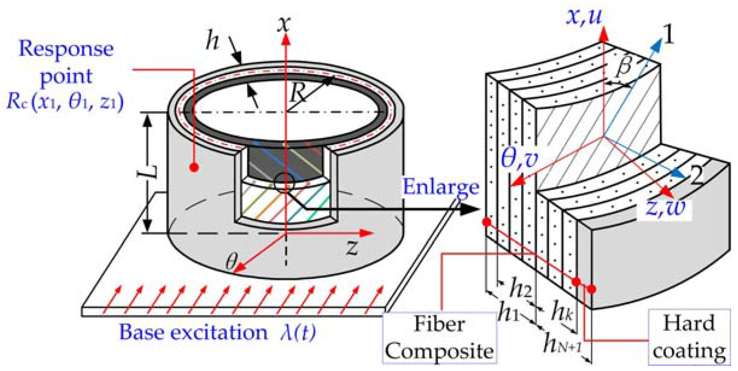
Figure 2.
Vibration characteristics analysis procedure of FCTS with hard coating.

Figure 3.
Finite element model of FCTS with hard coating: (a) Finite element model; (b) Schematic of hard coating and substrate.
Figure 3.
Finite element model of FCTS with hard coating: (a) Finite element model; (b) Schematic of hard coating and substrate.
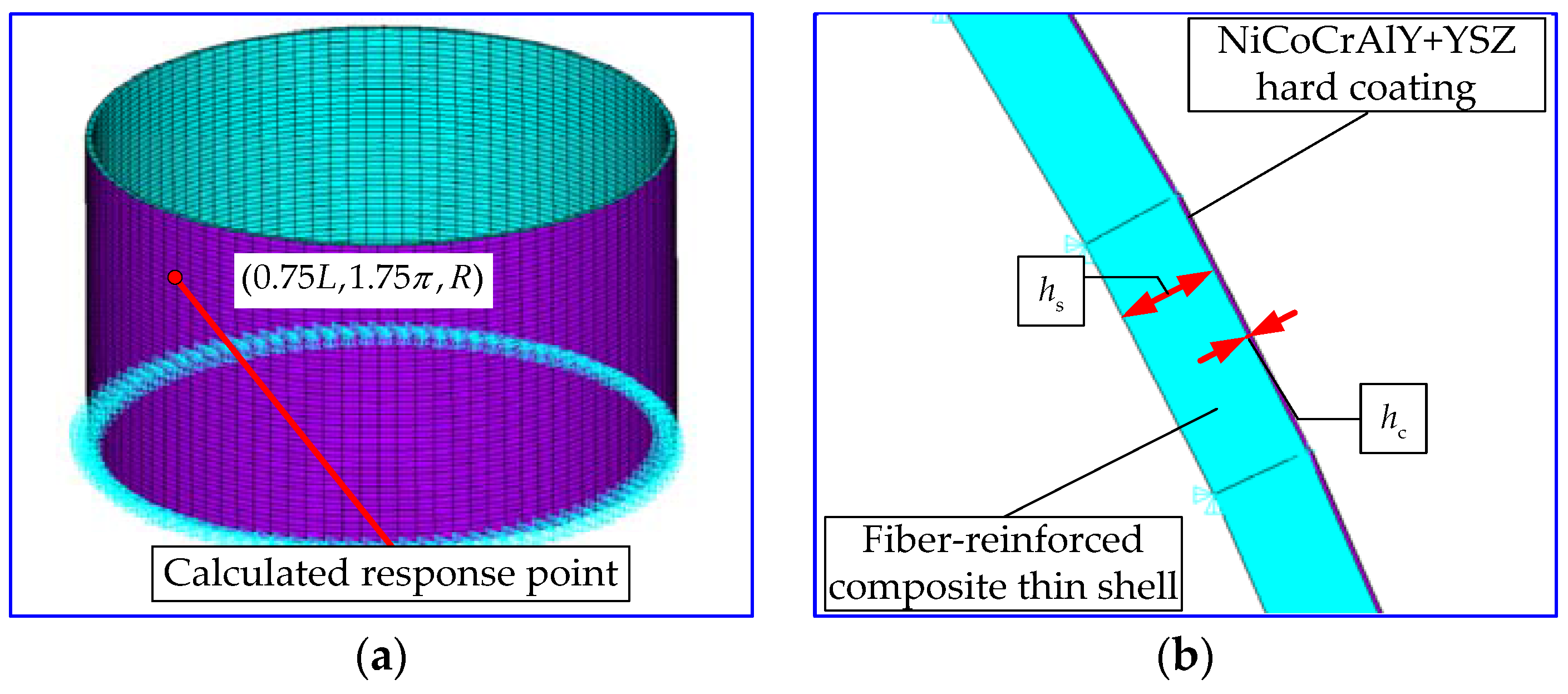
Figure 4.
The variation rate of resonant response of the composite shell corresponding to different elastic modulus of hard coating.
Figure 4.
The variation rate of resonant response of the composite shell corresponding to different elastic modulus of hard coating.

Figure 5.
The modal loss factor of the composite shell corresponding to different elastic modulus of hard coating.
Figure 5.
The modal loss factor of the composite shell corresponding to different elastic modulus of hard coating.
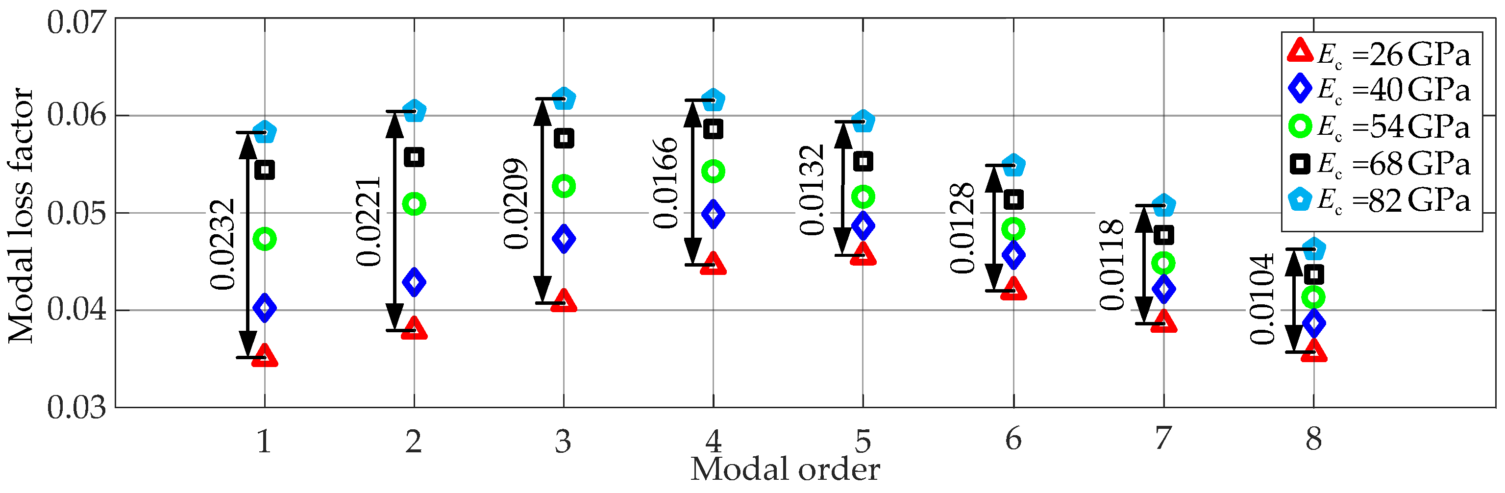
Figure 6.
The variation rate of resonant response of the composite shell corresponding to different loss factors of hard coating.
Figure 6.
The variation rate of resonant response of the composite shell corresponding to different loss factors of hard coating.

Figure 7.
The modal loss factor of the composite shell corresponding to different loss factors of hard coating.
Figure 7.
The modal loss factor of the composite shell corresponding to different loss factors of hard coating.
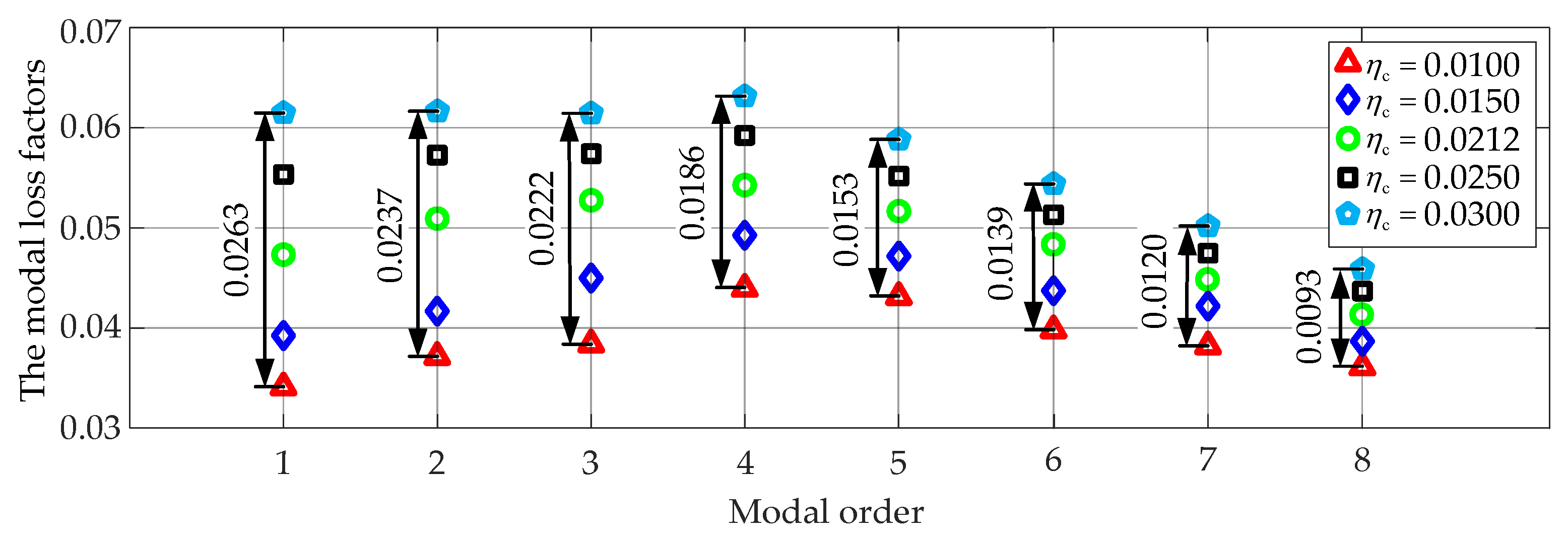
Figure 8.
The variation rate of resonant response of the composite shell corresponding to different thicknesses of hard coating.
Figure 8.
The variation rate of resonant response of the composite shell corresponding to different thicknesses of hard coating.
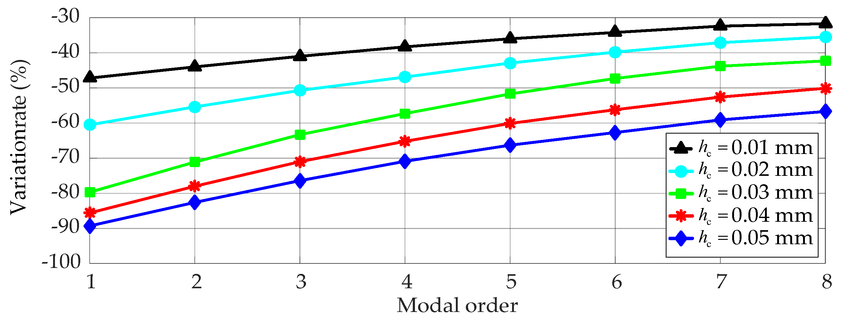
Figure 9.
The modal loss factor of the composite shell corresponding to different thicknesses of hard coating.
Figure 9.
The modal loss factor of the composite shell corresponding to different thicknesses of hard coating.


Table 1.
The geometry properties of FCTS and hard coating (mm).
| Material Type | Radius | Length | Thickness of Each Layer | Total Thickness |
|---|---|---|---|---|
| FCTS | 132.50 | 150.00 | 0.125 | 3.00 |
| Hard coating | 134.015 | 150.00 | 0.03 | 0.03 |
Table 2.
The material property of FCTS.
| (GPa) | (GPa) | (GPa) | ρf (kg/m3) | |||||
|---|---|---|---|---|---|---|---|---|
| 135 | 8.5 | 3.36 | 0.0046 | 0.0052 | 0.0098 | 0.33 | 0.02 | 1570 |
Table 3.
The comparison of the first eight natural frequencies and modal shapes of the FCTS obtained by theoretical calculations and the finite element method.
Table 3.
The comparison of the first eight natural frequencies and modal shapes of the FCTS obtained by theoretical calculations and the finite element method.
| Modal Order | 1 | 2 | 3 | 4 | 5 | 6 | 7 | 8 |
|---|---|---|---|---|---|---|---|---|
| Natural frequency Present H1 [Hz] | 958.7 | 1061.1 | 1203.3 | 1364.2 | 1782.6 | 1960.5 | 2283.5 | 2860.1 |
| Natural frequency ANSYS G1 [Hz] | 958.7 | 1058.6 | 1199.6 | 1361.5 | 1776.2 | 1952.5 | 2277.8 | 2855.0 |
| Difference [%] | 0 | 0.24 | 0.31 | 0.20 | 0.36 | 0.41 | 0.25 | 0.18 |
| Modal shape Present (m, n) |  |  |  |  |  |  |  |  |
| (1, 4) | (1, 5) | (1, 3) | (1, 6) | (1, 7) | (1, 2) | (1, 8) | (1, 9) | |
| Modal shape ANSYS (m, n) |  |  |  |  |  |  |  |  |
| (1, 4) | (1, 5) | (1, 3) | (1, 6) | (1, 7) | (1, 2) | (1, 8) | (1, 9) |
Table 4.
The comparison of the first eight resonant responses of the FCTS obtained by theoretical calculations and the finite element method (mm).
Table 4.
The comparison of the first eight resonant responses of the FCTS obtained by theoretical calculations and the finite element method (mm).
| Modal Order | 1 | 2 | 3 | 4 | 5 | 6 | 7 | 8 |
|---|---|---|---|---|---|---|---|---|
| Present H2 | 0.0501 | 0.0313 | 0.0164 | 0.0275 | 0.0250 | 0.0173 | 0.0157 | 0.0119 |
| ANSYS G2 | 0.0492 | 0.0309 | 0.0160 | 0.0265 | 0.0245 | 0.0170 | 0.0151 | 0.0116 |
| Difference [%] | 1.80 | 1.28 | 2.44 | 3.63 | 2.00 | 1.73 | 3.82 | 2.52 |
Table 5.
The comparison of the first eight modal loss factors of the FCTS obtained by theoretical calculations and the finite element method.
Table 5.
The comparison of the first eight modal loss factors of the FCTS obtained by theoretical calculations and the finite element method.
| Modal Order | 1 | 2 | 3 | 4 | 5 | 6 | 7 | 8 |
|---|---|---|---|---|---|---|---|---|
| Present H3 | 0.0487 | 0.0508 | 0.0523 | 0.0540 | 0.0516 | 0.0472 | 0.0446 | 0.0413 |
| ANSYS G3 | 0.0477 | 0.0496 | 0.0512 | 0.0520 | 0.0507 | 0.0459 | 0.0431 | 0.0393 |
| Difference [%] | 2.05 | 2.36 | 2.10 | 3.70 | 1.74 | 2.75 | 3.36 | 4.84 |
Table 6.
The influence of elastic modulus of hard coating on the natural frequency of the composite shell.
Table 6.
The influence of elastic modulus of hard coating on the natural frequency of the composite shell.
| Modal Order | 1 | 2 | 3 | 4 | 5 | 6 | 7 | 8 | |
|---|---|---|---|---|---|---|---|---|---|
| Nature frequency [Hz] | Uncoated | 950.7 | 1036.8 | 1217.4 | 1323.9 | 1723.1 | 1892.4 | 2202.9 | 2753.3 |
| Coated 26 GPa | 922.7 | 1015.3 | 1194.3 | 1301.7 | 1698.0 | 1862.3 | 2174.0 | 2720.1 | |
| Coated 40 GPa | 940.8 | 1038.4 | 1223.5 | 1333.5 | 1741.0 | 1913.2 | 2230.7 | 2792.6 | |
| Coated 54 GPa | 958.7 | 1061.1 | 1249.1 | 1364.2 | 1782.6 | 1960.5 | 2283.5 | 2860.1 | |
| Coated 68 GPa | 974.7 | 1081.1 | 1273.4 | 1391.2 | 1818.9 | 2002.2 | 2333.0 | 2923.1 | |
| Coated 82 GPa | 990.7 | 1100.7 | 1299.0 | 1417.6 | 1854.3 | 2040.0 | 2379.4 | 2982.3 | |
| Variation rate [%] | Coated 26 GPa | −2.9 | −2.1 | −1.9 | −1.7 | −1.5 | −1.6 | −1.3 | −1.2 |
| Coated 40 GPa | −1.0 | 0.2 | 0.5 | 0.7 | 1.0 | 1.1 | 1.3 | 1.4 | |
| Coated 54 GPa | 0.8 | 2.3 | 2.6 | 3.0 | 3.5 | 3.6 | 3.7 | 3.9 | |
| Coated 68 GPa | 2.5 | 4.3 | 4.6 | 5.1 | 5.6 | 5.8 | 5.9 | 6.2 | |
| Coated 82 GPa | 4.2 | 6.2 | 6.7 | 7.1 | 7.6 | 7.8 | 8.0 | 8.3 | |
Table 7.
The influence of elastic modulus of hard coating on the resonant response of the composite shell.
Table 7.
The influence of elastic modulus of hard coating on the resonant response of the composite shell.
| Modal Order | 1 | 2 | 3 | 4 | 5 | 6 | 7 | 8 | |
|---|---|---|---|---|---|---|---|---|---|
| Resonant response [mm] | Uncoated | 0.2468 | 0.1084 | 0.0446 | 0.0645 | 0.0518 | 0.0328 | 0.0279 | 0.0206 |
| Coated 26 GPa | 0.0960 | 0.0478 | 0.0223 | 0.0351 | 0.0306 | 0.0204 | 0.0180 | 0.0134 | |
| Coated 40 GPa | 0.0718 | 0.0392 | 0.0192 | 0.0313 | 0.0278 | 0.0189 | 0.0169 | 0.0127 | |
| Coated 54 GPa | 0.0501 | 0.0313 | 0.0164 | 0.0275 | 0.0250 | 0.0173 | 0.0157 | 0.0119 | |
| Coated 68 GPa | 0.0289 | 0.0236 | 0.0134 | 0.0237 | 0.0221 | 0.0157 | 0.0145 | 0.0111 | |
| Coated 82 GPa | 0.0091 | 0.0146 | 0.0104 | 0.0197 | 0.0192 | 0.0140 | 0.0131 | 0.0123 | |
Table 8.
The influence of loss factor of hard coating on the resonant responses of the composite shell.
Table 8.
The influence of loss factor of hard coating on the resonant responses of the composite shell.
| Modal Order | 1 | 2 | 3 | 4 | 5 | 6 | 7 | 8 | |
|---|---|---|---|---|---|---|---|---|---|
| Resonant response [mm] | Uncoated | 0.2468 | 0.1084 | 0.0446 | 0.0645 | 0.0518 | 0.0328 | 0.0279 | 0.0206 |
| Coated 0.0100 | 0.1106 | 0.0543 | 0.0252 | 0.0401 | 0.0343 | 0.0226 | 0.0196 | 0.0147 | |
| Coated 0.0150 | 0.0829 | 0.0437 | 0.0213 | 0.0344 | 0.0299 | 0.0203 | 0.0181 | 0.0137 | |
| Coated 0.0212 | 0.0501 | 0.0313 | 0.0164 | 0.0275 | 0.0250 | 0.0173 | 0.0157 | 0.0119 | |
| Coated 0.0250 | 0.0380 | 0.0246 | 0.0136 | 0.0241 | 0.0230 | 0.0158 | 0.0146 | 0.0114 | |
| Coated 0.0300 | 0.0163 | 0.0156 | 0.0100 | 0.0199 | 0.0196 | 0.0144 | 0.0129 | 0.0101 | |
Table 9.
The influence of thickness of hard coating on the natural frequency of the composite shell.
Table 9.
The influence of thickness of hard coating on the natural frequency of the composite shell.
| Modal Order | 1 | 2 | 3 | 4 | 5 | 6 | 7 | 8 | |
|---|---|---|---|---|---|---|---|---|---|
| Nature frequency [Hz] | Uncoated | 950.7 | 1036.8 | 1217.4 | 1323.9 | 1723.1 | 1892.4 | 2202.9 | 2753.3 |
| Coated 0.01 mm | 955.8 | 1052.3 | 1228.6 | 1349.7 | 1761.3 | 1935.9 | 2255.8 | 2823.3 | |
| Coated 0.02 mm | 957.2 | 1056.8 | 1236.9 | 1357.2 | 1772.3 | 1942.3 | 2271.1 | 2843.5 | |
| Coated 0.03 mm | 958.7 | 1061.1 | 1249.1 | 1364.2 | 1782.6 | 1960.5 | 2283.5 | 2860.1 | |
| Coated 0.04 mm | 960.0 | 1065.1 | 1258.7 | 1370.9 | 1792.3 | 1971.1 | 2298.8 | 2880.1 | |
| Coated 0.05 mm | 961.3 | 1069.0 | 1265.3 | 1377.2 | 1801.5 | 1982.1 | 2311.4 | 2896.8 | |
| Variation rate [%] | Coated 0.01 mm | 0.7 | 1.5 | 0.9 | 2.0 | 2.2 | 2.3 | 2.4 | 2.5 |
| Coated 0.02 mm | 0.5 | 1.9 | 1.6 | 2.5 | 2.9 | 2.6 | 3.1 | 3.3 | |
| Coated 0.03 mm | 0.8 | 2.3 | 2.6 | 3.0 | 3.5 | 3.6 | 3.7 | 3.9 | |
| Coated 0.04 mm | 1.0 | 2.7 | 3.4 | 3.6 | 4.0 | 4.2 | 4.4 | 4.6 | |
| Coated 0.05 mm | 1.1 | 3.1 | 3.9 | 4.0 | 4.6 | 4.7 | 5.0 | 5.2 | |
Table 10.
The influence of thickness of hard coating on the resonant response of the composite shell.
Table 10.
The influence of thickness of hard coating on the resonant response of the composite shell.
| Modal Order | 1 | 2 | 3 | 4 | 5 | 6 | 7 | 8 | |
|---|---|---|---|---|---|---|---|---|---|
| Resonant response [mm] | Uncoated | 0.2468 | 0.1084 | 0.0446 | 0.0645 | 0.0518 | 0.0328 | 0.0279 | 0.0206 |
| Coated 0.01 mm | 0.1303 | 0.0607 | 0.0263 | 0.0398 | 0.0332 | 0.0216 | 0.0189 | 0.0141 | |
| Coated 0.02 mm | 0.0975 | 0.0483 | 0.0220 | 0.0343 | 0.0296 | 0.0197 | 0.0175 | 0.0133 | |
| Coated 0.03 mm | 0.0501 | 0.0313 | 0.0164 | 0.0275 | 0.0250 | 0.0173 | 0.0157 | 0.0119 | |
| Coated 0.04 mm | 0.0355 | 0.0238 | 0.0129 | 0.0224 | 0.0207 | 0.0144 | 0.0132 | 0.0103 | |
| Coated 0.05 mm | 0.0264 | 0.0189 | 0.0105 | 0.0188 | 0.0175 | 0.0122 | 0.0114 | 0.0089 | |
© 2018 by the authors. Licensee MDPI, Basel, Switzerland. This article is an open access article distributed under the terms and conditions of the Creative Commons Attribution (CC BY) license (http://creativecommons.org/licenses/by/4.0/).
Share and Cite
MDPI and ACS Style
Li, H.; Zhou, Z.; Sun, H.; Sun, W.; Wen, B. Theoretical Study on the Influence of Hard Coating on Vibration Characteristics of Fiber-Reinforced Composite Thin Shell. Coatings 2018, 8, 87. https://doi.org/10.3390/coatings8030087
AMA Style
Li H, Zhou Z, Sun H, Sun W, Wen B. Theoretical Study on the Influence of Hard Coating on Vibration Characteristics of Fiber-Reinforced Composite Thin Shell. Coatings. 2018; 8(3):87. https://doi.org/10.3390/coatings8030087
Chicago/Turabian StyleLi, Hui, Zhengxue Zhou, Hai Sun, Wei Sun, and Bangchun Wen. 2018. "Theoretical Study on the Influence of Hard Coating on Vibration Characteristics of Fiber-Reinforced Composite Thin Shell" Coatings 8, no. 3: 87. https://doi.org/10.3390/coatings8030087
Note that from the first issue of 2016, this journal uses article numbers instead of page numbers. See further details here.