Tribological Properties of New Cu-Al/MoS2 Solid Lubricant Coatings Using Magnetron Sputter Deposition


1
College of Materials Science and Engineering, Jilin University, No. 5988 Renmin Street, Changchun 130025, China
2
Advanced Materials Research and Development Center, Zhejiang Industry and Trade Vocational College, No. 717 Fudong Road, Wenzhou 325003, China
3
College of Chemistry and Materials Engineering, Wenzhou University, No. 276 Xueyuan Middle Road, Wenzhou 325035, China
*
Author to whom correspondence should be addressed.
Coatings 2018, 8(4), 134; https://doi.org/10.3390/coatings8040134
Submission received: 10 February 2018
/
Revised: 24 March 2018
/
Accepted: 26 March 2018
/
Published: 6 April 2018
(This article belongs to the Special Issue Coatings Tribology)
Abstract
:The increasing demands of environmental protection have led to solid lubricant coatings becoming more and more important. A new type of MoS2-based coating co-doped with Cu and Al prepared by magnetron sputtering, including Cu/MoS2 and Cu-Al/MoS2 coatings, for lubrication applications is reported. To this end, the coatings were annealed in an argon atmosphere furnace. The microstructure and the tribological properties of the coatings prior to and following annealing were analyzed using scanning electron microscopy, energy dispersive spectrometry, X-ray diffractometry (XRD) and with a multi-functional tester for material surface properties. The results demonstrated that the friction coefficient of the Cu/MoS2 coating was able to reach as low as 0.07, due to the synergistic lubrication effect of the soft metal Cu with MoS2. However, the wear resistance of the coating was not satisfied. Although the lowest friction coefficient of the Cu-Al/MoS2 coatings was 0.083, the wear resistance was enhanced, which was attributed to the improved the toughness of the coatings due to the introduction of aluminum. The XRD results revealed that the γ2-Cu9Al4 phase was formed in the specimen of Cu-Al/MoS2 coatings. The comprehensive performance of the Cu-Al/MoS2 coatings after annealing was improved in comparison to substrate heating, since the heat-treatment was beneficial for the strengthening of the solid solution of the coatings.
1. Introduction
The typical materials that can be used as solid lubrication coatings are mainly soft metals (Au, Ag, Cu, Pb), metal compounds (metal oxides, metal halides, metal sulfides, metal selenides), organic materials (Polytetrafluoroetylene, Polyethylene, Polyamide) and et al [1,2,3,4]. Among all the metal sulfide systems (FeS, WS2, MoS2, ZnS), MoS2 is widely used, due to its excellent lubricating properties. The excellent lubrication performance of MoS2 is due to the hexagonal crystal structure of the corresponding layer. MoS2 exhibits strong chemical bonds within the layers (Mo-S bonds) and weak Van der Waals bonds between individual MoS2 layers, which cause it to have an anisotropic characteristic. Furthermore, the anisotropy of its crystal structure can improve its load capacity, because the edge planes of MoS2 have high reactivity and hardness [5]. Conversely, as is commonly known, the usage environment has a significant effect on the performance of MoS2-based lubricating coatings; for example, the service temperature [6], the humidity [7] and the contact load [4] will all affect the service life of MoS2-based lubricant coatings. To improve the comprehensive performance of MoS2-based coatings, a large amount of research has already been conducted. The Physical Vapor Deposition (PVD) method is one of the most efficient methods for preparing MoS2-based lubricant coatings. Experimental results reveal that metal doping presents a simple and economical method of improving the comprehensive properties of MoS2-based coatings. It is generally believed that doped soft metals, such as Au [8,9,10] and Pb [11,12], can reduce the friction coefficients of coatings due to the synergistic lubrication effects, while such coatings have the disadvantage of poor wear resistance. In contrast, the co-doping of metals such as Ti [13,14], Ni [15], Cr [16,17], Al [10,18], Zr [19], Nb [20] and Mo [21] would be appropriate for reducing the friction coefficient and improving the mechanical properties of the coatings. Complementary multi-metal properties can be achieved by using magnetron co-sputtering, which makes up for the deficiency of single-metal. Therefore, there is great potential value in research into the coatings of binary metal co-doped MoS2. Until recently, few studies had been carried out on the preparation of MoS2 composite coatings through binary metal co-doping. ILIE [21] studied the MoS2/(Ti, Mo) composite coatings through Ti-Mo co-doping, and found that the apparent scratches occurred during wear testing, and the overall performance was worse when compared to MoS2/Ti, indicating that the addition of Mo did not improve the friction properties of the coatings. Ren and co-workers [22] fabricated MoS2-based coatings by means of the co-sputtering of Pb-Ti, one soft and one hard material, and determined that the surface roughness of the coatings decreased as the Pb content increased. Additionally, the microstructure of cross-section turned from porous columnar into the dense amorphous. The hardness and elastic modulus of the coatings decreased as the Pb content increased, and the tribological properties were improved. Adversely, Pb is an element that causes environmental problems, while the processing of Ag and Au is not easy to control for a high sputtering yield. Since copper and copper alloys are known to be good lubricant additives [23,24], Cu was selected to be the soft metal incorporating into MoS2, with a view to the practical application of the lubricant coatings. In terms of the strengthening and potential oxidation resistance at higher ambient temperature of the solid solutions, Al was selected as a binary metal for doping into MoS2. For the purposes of thermal stress reduction and the improvement of the surface uniformity of the coatings, subsequent annealing of the coatings was performed.
Firstly, a series of Cu-MoS2 coatings was prepared by co-sputtering under various power values of the Cu target. Through the optimization of the process parameters, the Cu-MoS2 coatings with superior tribological properties were obtained. Subsequently, the co-sputtered Cu-Al/MoS2 coatings were prepared to further optimize the MoS2-based coating process. Finally, the prepared composite coatings were annealed under argon atmosphere to obtain superior tribological properties. Through this process, Cu-Al/MoS2 composite coatings with a new composition system were discovered. The optimal process parameters of the composite coatings were obtained based on the analysis of the relationship between the microstructure and the tribological properties.
2. Materials and Methods
2.1. Preparation of Coatings
The composite lubrication coatings were deposited by a DEER DE500 magnetron sputtering system. A Φ50 mm target of Al (99.999%) and a Φ50 mm target of Cu (99.995%) with direct current (DC) sputtering power, as well as a Φ50 mm target of MoS2 (99.99%) with radio frequency (RF) power had been used. The coatings were deposited on polished SUS 201 steels and single-crystal silicon wafers synchronously. The test steels of 20 × 20 × 1 mm3 in dimensions were designed for friction tests. In addition, the steel had an uncoated average roughness (Ra) below 24 nm (mirror finish) and a hardness of 30 HRC. The silicon wafers were used for structural analysis. The substrates were initially cleaned ultrasonically in acetone and an alcohol bath for 20 min, consequently rinsed in deionization water, as well as dried under nitrogen and placed in the vacuum chamber. Prior to coating deposition, an aluminum intermediate layer of approximately 35 nm in thickness was deposited on the substrate. Then deposition of the main bulk of the MoS2-based coatings was performed for 3 h. The base pressure in the sputter chamber was about 5 × 10⁻⁴ Pa and the working pressure was 1 Pa. Argon was utilized as the working gas for sputtering. The target-substrate distance was 16 cm and the substrate rotation speed was 5 rpm. As presented in Table 1, a series of MoS2-based coatings was prepared by adjusting the power values of the Cu and Al target, while the power values of the MoS2 target was retained at 100 W. To improve the bonding force between the substrate and the coating, various substrate temperatures were also utilized in preparing the coatings.
2.2. Annealing of Coatings
It is generally recognized that post-annealing release of residual stress of the coatings [25], without significant phase and lattice constant changes in the as-deposited coatings, even subsequently to annealing under vacuum at higher temperature [26]. Adversely, the results in [27] demonstrated that the MoS2 layers became crystalline following annealing at approximately 350 °C. In order to observe the effect of annealing temperature on the Cu-Al/MoS2 composite coatings properties, the coatings were annealed at 300 °C, 400 °C and 500 °C under argon atmosphere based on the phase diagram of Cu-Al [28]. The chamber of controlled atmosphere furnace was evacuated down to a residual pressure of 3 Pa and consequently was purged with argon to remove oxygen. These processes were repeated three times. The argon pressure during annealing was 0.06 MPa. The heating rate was 5 °C/min and the holding time was 2 h. Finally, the coatings were cooled down to the room temperature while the furnace was turned off. The microstructures and tribological properties of the coatings along with subsequent annealing at various temperatures were analyzed and compared.
2.3. Structure Characterization
The 3D-reconstruction of the surface roughness of the composite coatings was obtained with a scanning electron microscope (SEM; Phenom XL, Phenom-World B.V., Eindhoven, The Netherlands). Both the microstructure and cross-sectional morphology of the coatings were observed using a field emission scanning electron microscopy (FESEM; Hitachis-4800, Hitachi Co. Ltd., Tokyo, Japan). The elemental compositions of the coatings were characterized with an X-ray energy-dispersive spectrometer (EDS; Horiba EX250, Horiba Co. Ltd., Kyoto, Japan). The phase structures of the coatings were examined by an X-ray diffractometer (XRD; Bruker D8 Advance, Bruker Inc., Karlsruhe, Germany) with Cu Kα radiation. The scanning range was from 10° to 65° and the scanning rate was 5°/min.
2.4. Tribological Experiments
A reciprocating friction and wear tester (MFT-4000, HuaHui Instruments technology Co. Ltd., Lanzhou, China) was utilized in the tribological testing of the coatings with a ball-on-plate configuration. The friction and wear characteristics of the coatings were evaluated at 22 ± 2 °C, while the relative humidity in testing was approximately 60 ± 10%. The tribological testing were carried out with 2 Hz reciprocating frequency, 5 mm stroke length, 10 N normal forces and a GCr15 steel ball (Φ 4 mm; hardness HRC60) as the friction pair. The corresponding theoretical initial Hertz contact pressure was 1.24 GPa. The average friction coefficients were automatically recorded with a computer. Subsequently to tribological testing, the SEM and optical microscope (OM; Zeiss Scope A1, Carl Zeiss, Gottingen, Germany) were utilized to observe the morphology of the wear tracks. The adhesion quality of the MoS2-based coatings to the steel substrate was obtained by use of the MFT-4000 scratch tester with a 0.2 mm tip radius diamond indenter. Testing parameter was a scratch length of 5 mm at a load rate of 100 N/min. The different depth profiles of the wear tracks were examined with a surface profilometer (JB-4C; Shanghai Taiming Optical Instrument Co. Ltd., Shanghai, China), that was the grinding crack depth along with the grinding crack width was assumed consistent. The wear scar volumes were calculated according to the Archard wear equation [29] by measuring the average cross-sectional area of track profiles and then multiplying for the track length. The result was used to compare wear rates qualitatively for the errors would exist in the measurements of cross-sectional area with the JB-4C type surface profilometer.
3. Results and Discussion
3.1. Coating Composition and Structural Characterization
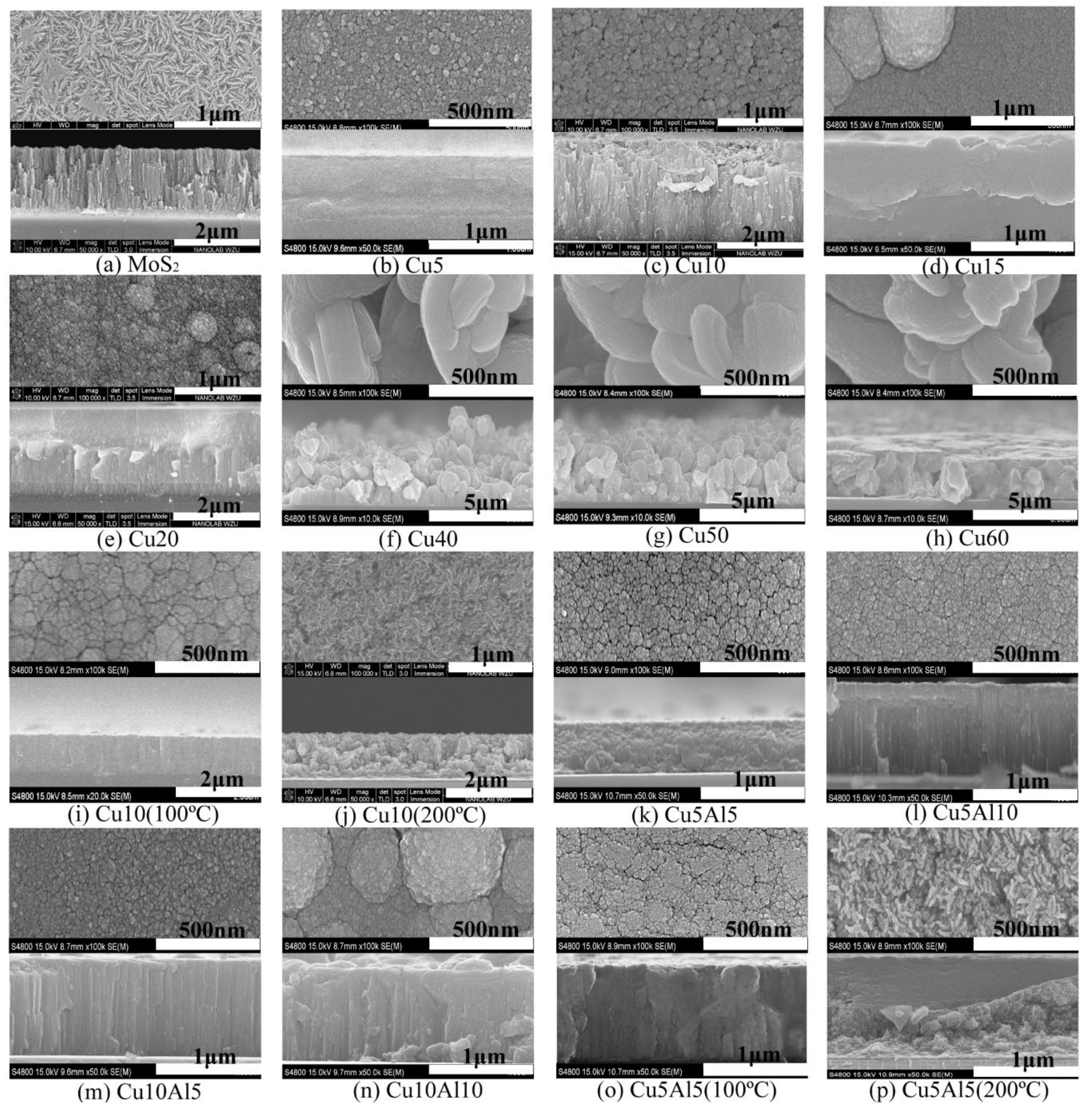
Figure 1 depicts the surface and cross-sectional micrographs of the composite coatings prepared with various process parameters. Figure 1a presents a pure MoS2 coating with worm-shaped surface morphology, which was consistent with the results reported in [30]. The cross-section morphology of the MoS2 coating was lamellar perpendicularly to the surface. Figure 1b–h presents the micrographs of the Cu/MoS2 coatings prepared using magnetron co-sputtering and the DC power of Cu target ranged from 5 W to 60 W. The surfaces of the Cu40, Cu50 and Cu60 coatings turned into coarse grained shapes, whereas the cross-section displayed irregular hill shapes with an incompact microstructure. The surface morphologies of the Cu5, Cu10 and Cu20 coatings were smooth, mainly displaying low-sized particles of approximately 20–50 nm, whereas the cross-section presented a dense morphology. Adversely, a low amount of grains of approximately 100–300 nm existed on the coating surfaces of the Cu15 and Cu20 coatings. The cross-sectional microstructure of the Cu10 coating was lamellar perpendicularly to the surface, which was more compact compared to the pure MoS2 coating. The cross-section of the Cu20 coating was densely columnar perpendicularly to the surface. Figure 1i,j depict the surface micrographs of the Cu10 coatings deposited at 100 °C and 200 °C. The surface morphology of the coatings changed from granular to worm-like as the temperature increased from 100 °C to 200 °C, and the cross-sectional structure became looser. The results demonstrated that the appropriate amount of Cu-doping changed the growth mode of MoS2, which led to the transformation of the coatings from columnar to densely granular. As the DC sputtering power increased, the granular microstructure on the surface grew rapidly and the surface roughness increased. Consequently, the power range of 10 W–20 W was appropriate for preparing a uniform and dense coating. The substrate-heating accelerated the formation of granular microstructure and increased the sputtering rate of Cu under the same sputtering power. The worm-like morphology in the Cu10 (200 °C) coating similarly to the pure MoS2 coating was observed. Similar results were found in the literature [31]. The results indicated that the increasing of substrate-heating temperature was beneficial to the formation of MoS2.
Figure 1k–n presents the surface and cross-sectional micrographs of the coatings, prepared simultaneously using magnetron co-sputtering of the Cu and Al targets. A granular surface morphology with tiny gaps was observed in the Cu5Al5 coating. Figure 1n illustrates certain particles with diameter in the total range of 200–500 nm were generated on the Cu10Al10 coating surface. The cross-sectional morphology of the Cu5Al5 coating was dense granular, whereas the other three coatings were columnar. Figure 1o,p presents the morphologies of the Cu5Al5 composite coatings, as prepared with the substrates heated to 100 °C and 200 °C. Figure 1o presents the granular surface morphology of the Cu5Al5 (100 °C) coating with apparent agglomeration, and the tiny gaps between the agglomerated particles decreased. Moreover, the surface morphology of the Cu5Al5 (200 °C) coating turned into a worm-like shape, whereas the cross-section demonstrated loose microstructure, as presented in Figure 1p, which was consistent with the Cu10 (200 °C) coating. The microstructure analysis of the bimetallic co-sputtered coatings revealed that Al-doping promoted the dense growth of the coatings. Also, to avoid the high-sized grains on the coating surface, the sputtering power of Al and Cu targets should also be reduced properly.
Figure 2 shows the morphologies of the MoS2-based coatings prior to and following annealing at 300 °C, 400 °C and 500 °C under argon atmosphere. Figure 2a presents the surface microstructure of the MoS2 coatings prior to and following annealing. There was no apparent change occurred in the surface morphology subsequently to various annealing temperatures. Figure 2b presents the tendency of single grains to agglomerate on the Cu10 coating, whereas the gaps among agglomerations reduced gradually as the temperature increased to 500 °C. Figure 2c presents that the large grain on the Cu20 coating surface disappeared following annealing at 300 °C. The gaps among the surface grains were gradually reduced and the grain size increased following annealing at 400 °C. The grain size of the coating surface increased significantly after annealing at 500 °C. Figure 2d–f presents the surface morphology of the Cu5Al5 coatings prior to and following annealing at different substrate temperatures. The grain-size and compactness of the Cu5Al5 coating surface increased gradually as the annealing temperature increased. The Cu5Al5 (100 °C) and Cu5Al5 (200 °C) coating surfaces also exhibited good uniformity and compactness as the annealing temperature increased. The surface morphology of the Cu5Al5 (200 °C) was similar to the Cu10 (200 °C) coating, which indicated that similar effects in the Cu-Al/MoS2 coatings might exist while the substrate was heated.
Table 2 presents the atomic percentages of the elements in the Cu/MoS2 coatings. The typical EDS spectrum of Cu10 and Cu20 were shown in Figure 3a,b. The percentage of Cu atoms in the coating increased gradually as the sputtering power increased. The content of Cu in the coating increased from 9.57 at% to 25.13 at%, which indicated the higher sputtering efficiency of Cu within the power range of 10 W–20 W. The ratios of NS/NMo in the Cu5–Cu50 coatings were lower than the pure MoS2 coating, which occurred due to the reverse sputtering of S during the deposition. The reverse sputtering would decrease the deposition rate, which was good for the MoS2 formation [32]. The value of NS/NMo in the Cu5 coating was below 1, whereas fewer S atoms were not conducive to the formation of the MoS2 (002) basal plane [22] which affected the tribological properties of the coatings. The substrate-heating was beneficial to the deposition of Cu atoms, thereby further affecting the tribological properties of the coatings.
The EDS analysis results of the Cu-Al/MoS2 coatings are presented in Table 3. The typical EDS spectrum acquired from the area of 10 × 10 μm2 on the Cu5Al5 coating was shown in Figure 3c. The results indicated that Al-doping promoted the deposition of Cu atoms on the substrate, whereas the substrate heating significantly inhibited the deposition of Cu atoms on the substrate. This might be due to the fact that a competition occurred as a result of partial substitution of Al with Cu. Being the coatings might form a solid solution or an intermediate phase during sputtering and annealing [33]. According to [34], the α-Cu phase would preferentially be produced in the MoS2-based coatings during the co-sputtering of Cu and Al, followed by a γ2-Cu9Al4 intermediate phase with the minimum activation energy. In addition, the NCu/NAl value of the Cu5Al5 coating shown in Table 3 was the most consistent with the γ2-Cu9Al4 intermediate phase. Another consideration is the strength and hardness of the Cu-Al/MoS2 coatings might increase, whereas the brittleness of the coatings might also be caused by the new phase.
Figure 4a presents the X-ray diffraction patterns of the Cu/MoS2 coatings. It demonstrated that the copper phase increased gradually as the Cu target power increased. The crystallization peak of the coatings prepared at low sputtering power of the Cu target was weak, and an amorphous-based structure of the coatings could be deduced, which was consistent with the result found in [22]. Figure 4b presents the XRD patterns of the Cu10 coating subsequently to annealing and the Cu10 coating with the substrate heating. It could be observed that the annealing temperature had an apparent effect on the crystalline of the coatings. When the substrate was heated to 200 °C, the crystallization peak between 10° and 15° was enhanced. It meant that substrate heating was in favor of the crystallization of MoS2, and MoS2 tent to be formed with the (002) basal plane parallel to the surface. The XRD patterns of the annealed coatings also proved that annealing could be more beneficial to enhance the crystallization of the coatings than substrate heating.
Figure 4c,d presents the XRD patterns of the Cu5Al5 coating with substrate heating and the Cu5Al5 coating following annealing. To a certain extent, the Cu and Al co-doping into MoS2 inhibited the formation of the MoS2 crystal structure due to the formation of solid solution or intermediate phase. Simultaneously, the XRD peaks of aluminum phase were not apparent, caused by the Al solid solubility not being exceeded and the overlapping with the MoS2 (002) peak at 2θ = 13° in Figure 4c [18]. In addition, the XRD patterns of the Cu5Al5 (200 °C) coating also revealed the apparent diffraction peaks of Cu3MoO2O9 and Al2O3. Figure 4d presents the XRD patterns of the Cu5Al5 coating annealed under argon atmosphere, which demonstrated that the γ2-Cu9Al4 phase was formed in the coatings, as reported in [34]. The results indicated that the annealing had beneficial effects on the formation of mesophase in the Cu-Al/MoS2 coatings.
3.2. Friction and Wear Evaluation
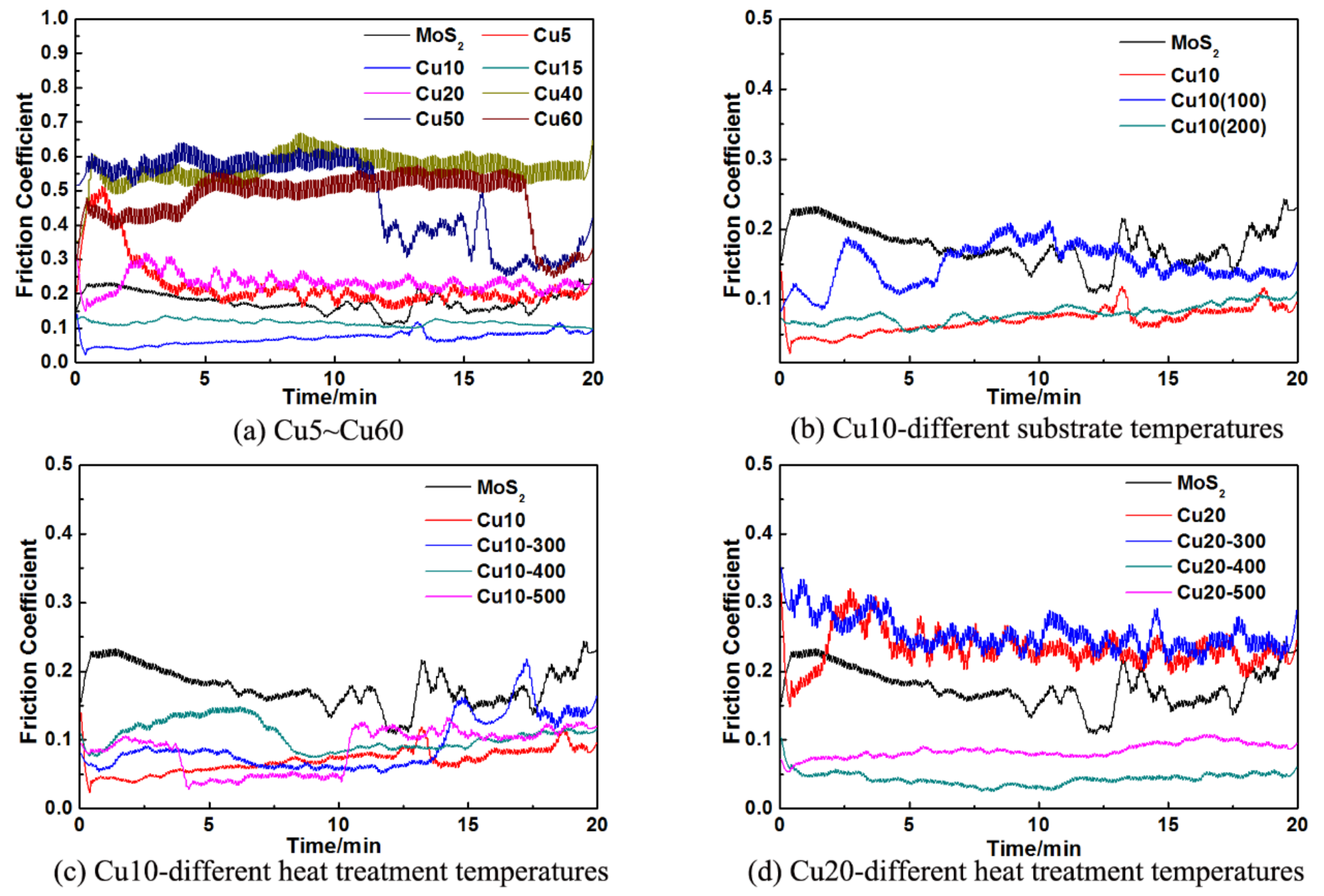
Figure 5 presents the friction coefficient curves of the Cu/MoS2 coatings. The friction coefficient decreased firstly then increased as the Cu target power increased, as presented in Figure 5a. The friction coefficients of the Cu10 and Cu20 were even lower compared to the pure MoS2 coating. The average friction coefficient of the Cu10 coating was 0.07, which was the lowest among the Cu/MoS2 coatings. In Figure 5b, the friction coefficient of the Cu10 (200 °C) was 0.08, which was lower compared to the Cu10 (100 °C), whereas both were higher than the Cu10 coating. The soft metal Cu doping into MoS2 could reduce the friction coefficient of the MoS2-based composite coatings. The EDS results demonstrated that the friction coefficient of the Cu10 coating with the NS/NMo ratio of 1.18 was the lowest, which was consistent with the results found in [35]. It meant that the Cu10 coating was relatively easy to obtain a MoS2 (002) basal plane, parallel to the substrate. In addition, the morphology of the Cu10 coating with smooth and dense surface, dense cross-sectional lamellar mentioned above were beneficial to maintain the low friction coefficient of the coatings in the humid environment based on the [36]. In Figure 5c,d, the Cu10 and Cu20 coatings annealed under argon atmosphere displayed an overall friction coefficient increase. When the heat treatment temperature increased to 500 °C, the Cu10 coating had the lowest average friction coefficient (0.088). Moreover, the minimum average friction coefficient of the Cu20 coating was 0.074, when the heat treatment temperature increased to 400 °C. The results indicated that the annealing had more influence on the friction coefficient than substrate heating. The average friction coefficients were reduced as the annealing temperature increased in general.
Considering that the friction coefficient of the Cu5Al5 coating (0.083) was the lowest among the Cu-Al/MoS2 coatings, only the friction coefficient curves of the Cu5Al5 coatings treated at various temperatures were displayed in Figure 6. Figure 6a presents the friction coefficients of the Cu5Al5 coatings at various substrate heat-treatment temperatures and the friction coefficient of Cu5Al5 (100 °C) coating had a maximum value of 0.164. The friction coefficients, as presented in Figure 6b–d, decreased as the heat treatment temperature increased. The friction coefficient of the Cu5Al5 coating annealed at 400 °C was minimum (0.076), where the Cu5Al5 (100 °C) had the lowest friction coefficient (0.068) at the same temperature. The friction coefficient of the Cu5Al5 (200 °C) coating annealed at 500 °C had the lowest value of 0.075. Similar to the Cu/MoS2 coatings, the annealing was more effective than the substrate heating on the reduction of friction coefficient. Above all, the recommended heat treatment temperature was generally in-between 400 °C and 500 °C.
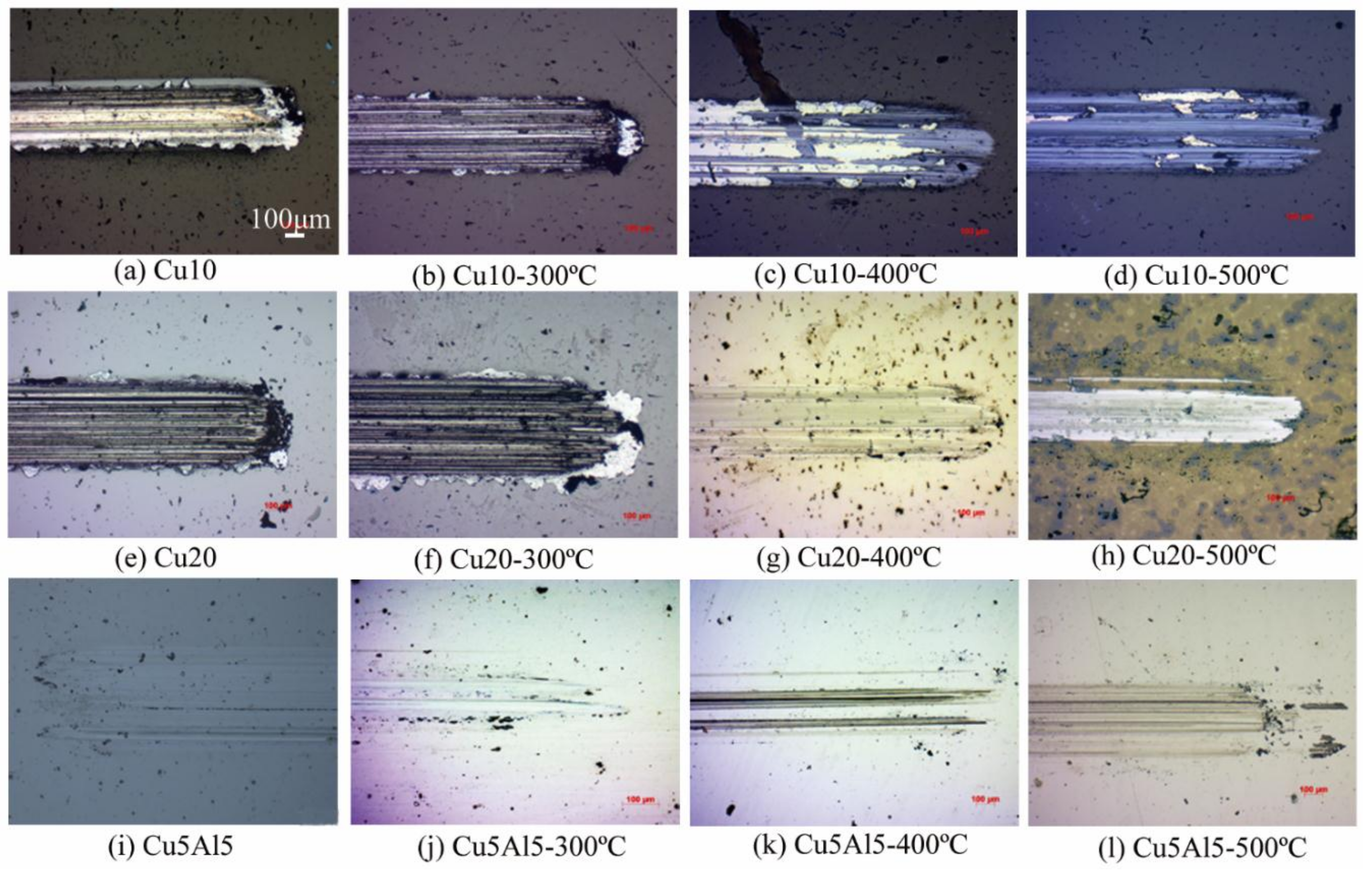
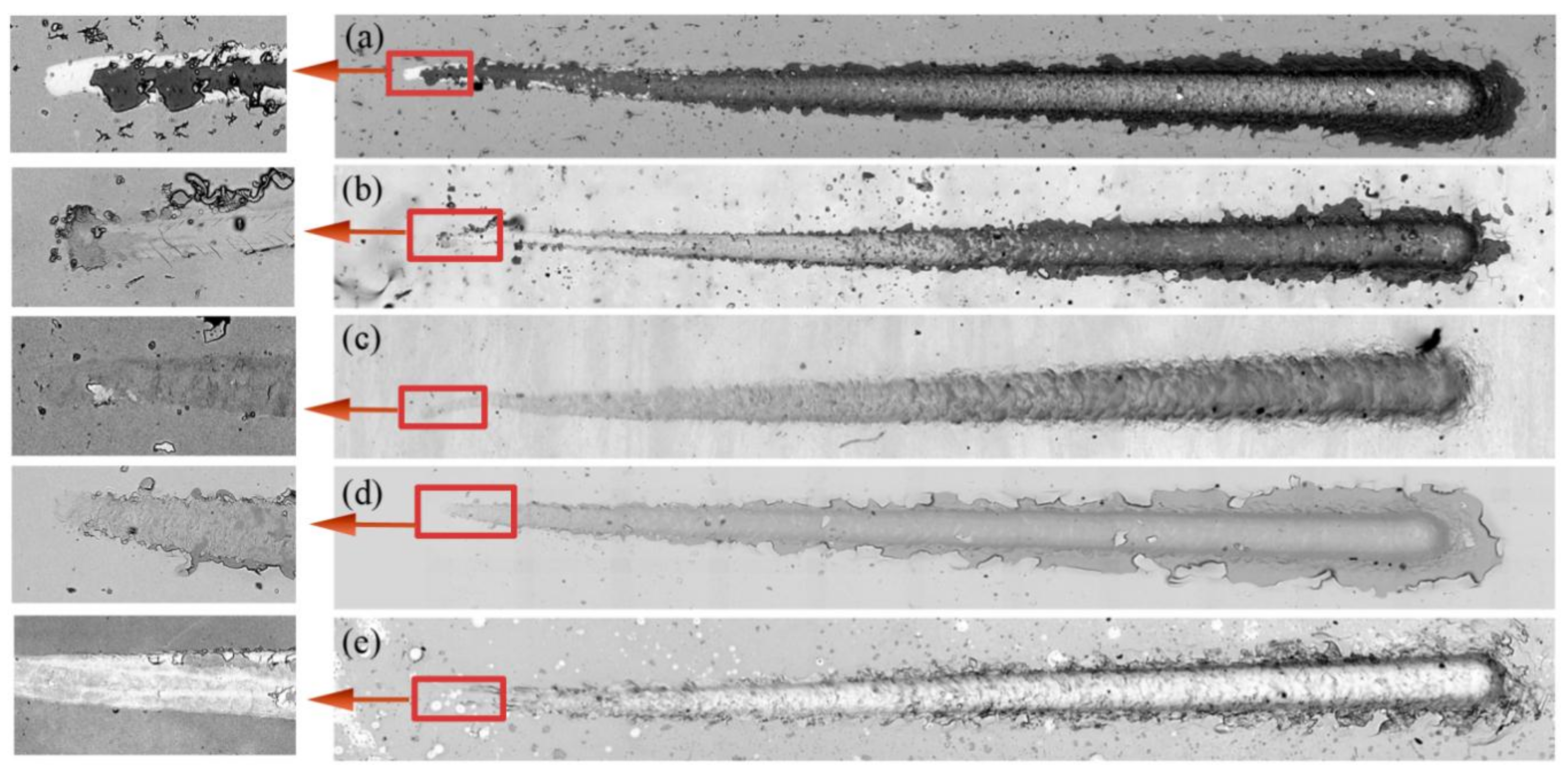
Figure 7 presents the typical OM micrographs of the wear tracks o the MoS2-based coatings. As presented in Figure 7a,e, the wear debris was pushed to the edges of the wear tracks, and there were obvious furrows along with wear tracks on the Cu/MoS2 coatings. Following annealing, the higher wear resistance of the Cu/MoS2 coatings would be inferred by the OM micrographs. The results might be caused by a higher density of the coatings according to the SEM morphologies in Figure 2. The wear track of the Cu5Al5 coating, as presented in Figure 7i, was relatively narrower compared to the Cu/MoS2 coatings, whereas a low amount of wear debris accompanied with shallow furrows existed along the sliding direction. This indicated that the wear degree was significantly lower compared to the Cu/MoS2 coatings. It also illustrated that the co-doping of Al and Cu could be conducive to the abrasion resistance of the coatings for the formation of the new mesophase. The worn surfaces presented in Figure 7 were covered with grooves parallel to the sliding direction, which were typical features of the abrasive wear.
3.3. Wear Mechanisms
Scratch testing can be used to evaluate the mechanical failure modes of the coatings. Figure 8 demonstrated the features of gross spallation in the Cu10 coatings case (Figure 8a), brittle tensile cracking followed by gross spallation in the Cu20 coatings case (Figure 8b), conformal cracking followed by gross spallation in the Cu5Al5 (100 °C) coatings case (Figure 8d), conformal cracking followed by bulking spallation in the Cu5Al5 coatings case (Figure 8c) and the Cu5Al5 (200 °C) coatings case (Figure 8e). The hardness of coatings with the tensile cracking followed by spallation was generally considered higher than the coating with conformal cracking followed by spallation and buckling failure, which meant that the Cu20 coatings had a higher hardness. Bulking spallation in the Cu5Al5 and Cu5Al5 (200 °C) coatings meant that the MoS2 co-doping with Cu and Al improved the toughness of the coatings. The typical wear mechanism of these coatings was the adhesive wear from the results presented in Figure 8.
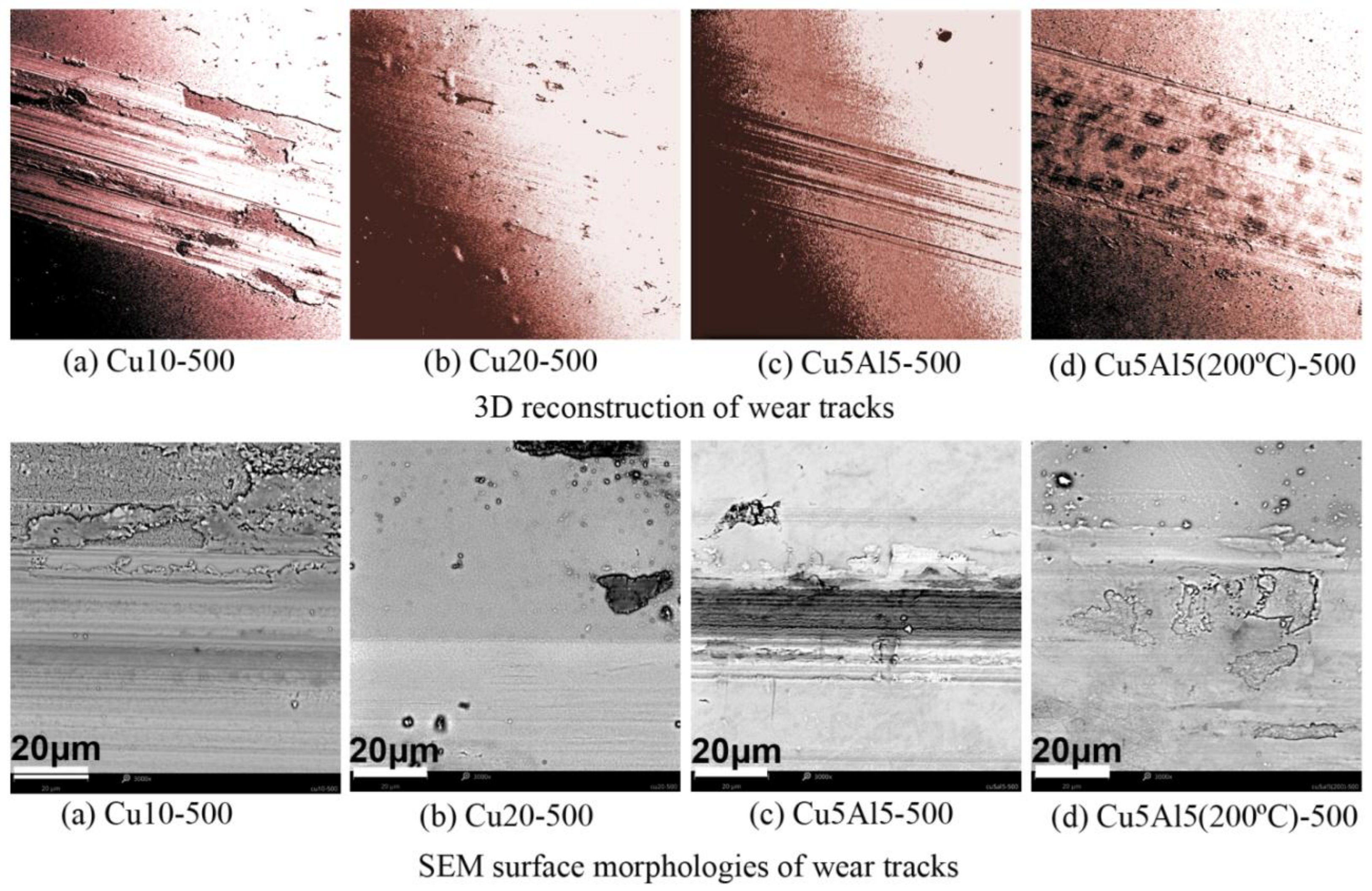
The SEM morphologies and 3D reconstructions of the worn surfaces are presented in Figure 9. Adhesive traces were observed on the worn surfaces of the Cu10 and Cu5Al5 (200 °C) coatings (Figure 9a,d). It was clear that these severe damages resulted from the shearing and rupture of the adhesive junctions between two contacting surfaces. The Cu phase on the friction surface of the Cu10 coating might be softened by braking, which could generate adhesion and lead to material transfer (Figure 9a). The SEM micrographs of typical worn surfaces demonstrated negligible wear scar in the Cu20 coating (Figure 9b), which might be benefit for the enhancement of surface hardness as mentioned above.
The deeper grooves caused by the hard asperities in Figure 9c indicated a primary mechanism of abrasive wear. Hence, a significantly low amount of oxide patches might exist in wear traces according to the EDS analysis (Figure 10a). The EDS results of the Cu5Al5 coating in Figure 10b indicated that a small amount of iron filings produced, while the content of oxygen was less than the Cu10 coating (Figure 10a). Therefore, an oxidation-abrasion mechanism could occur during tribo-testing of the coatings. The worn surface of the Cu5Al5 coating was characterized by typical features of adhesive and abrasive wear, considering the results in Figure 8c. The iron filings or oxide patches on the friction surface could lead to severe wear and deep grooves on the surface.
3.4. Oxidation Resistance and Wear Resistance
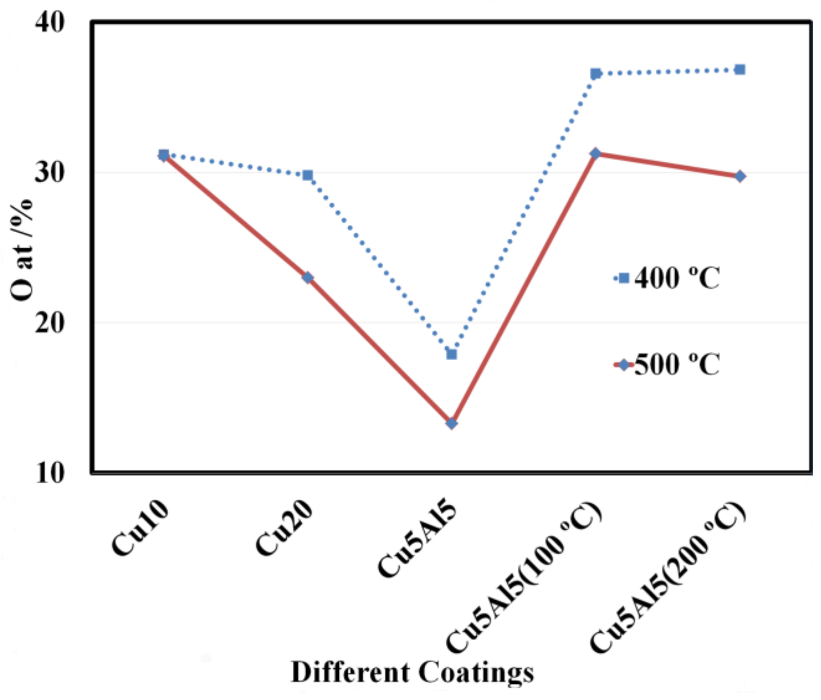
The oxidation resistance was enhanced according to the EDS testing results on the wear tracks as presented in Figure 11. The Cu5Al5/MoS2 coating had the best antioxidant properties among all coatings, especially following the annealing at 500 °C. This was because the mesophase promoted the densification of the coatings, and then improved the abrasion resistance and increased the anti-oxidation ability of the coatings during wear tests.
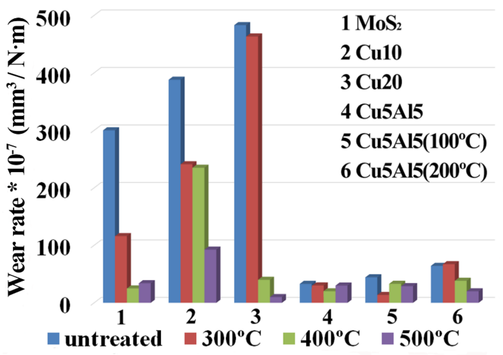
Figure 12 presents a qualitative comparison of the wear rate of MoS2-based coatings prior to and following annealing. The results showed that both the pure MoS2 and Cu/MoS2 coatings had weak wear resistance. By doping soft metal Cu with MoS2, the friction coefficient of the coatings decreased due to the synergistic lubricating effects. The wear resistance of the Cu/MoS2 coating was not satisfactory without heat treatment. By analyzing the oxidation potential of Cu, namely the φθ(Cu2+/Cu+) = 0.153 V and φθ(Cu2+/Cu) = 0.337 V, the oxygen absorption performance of Cu during wear test was weak. Following annealing, the wear rates of the Cu/MoS2 coatings began to decrease, especially subsequently to annealing at 500 °C. The SEM micrographs indicated that the dense surface of the coating might be the key factors that affected antioxidant properties.
The abrasion resistance of the coatings co-doped with Cu and Al was significantly enhanced. On the one hand, the addition of aluminum improved the toughness of the coatings; and on the other hand, the formation of Cu-Al mesophase had contributed to the antioxidant property and moisture resistance of the Cu-Al/MoS2 coatings. The wear life of the Cu-Al/MoS2 coatings was thereby improved. Given the oxidation potential of φθ(Al3+/Al) = −1.63 V, therefore, Al in the coatings oxidize to Al2O3 was easier than Cu. The protective Al2O3 layer would help to inhibit the oxygen further infiltrate into the coating matrix. Following annealing at 400 °C, the wear rate of the Cu5Al5 coating decreased to be the lowest. The loose worm-like surface morphology of the Cu5Al5 (200 °C) coating led to an increasing wear rate, but subsequently to an annealing at 500 °C, the wear rate decreased.
4. Conclusions
- The Cu/MoS2 composite coatings with various Cu contents were prepared by magnetron sputtering and the tribological properties were tested at room temperature. The Cu10 coating had the lowest friction coefficient among all Cu/MoS2 coatings, whereas the friction coefficient of the Cu5Al5 coating was the lowest in all Cu-Al/MoS2 coatings. The average friction coefficients of the Cu10 and the Cu5Al5 coatings were both lower than the pure MoS2 coating. The abrasion resistance of the coatings co-doped with Cu and Al was significantly enhanced through wear rate qualitative comparison. It was very probable that the γ2-Cu9Al4 phase in the co-sputtered Cu-Al/MoS2 coatings improved the wear resistance.
- Through comparison and analysis of the microstructures observed by SEM, the Cu5Al5 coating with enhanced tribological properties had a smooth surface and a dense cross-sectional non-columnar microstructure. The co-sputtering deposition with Cu and Al led to a smooth surface on the coating. This would lead to the flaking avoidance of the coatings in the friction experiments as well. Following annealing, the grain growth further promoted the compactness of the Cu5Al5 coatings and the wear resistance improvement all at the same time. That was both the low friction coefficient and low wear rate were maintained under the test conditions.
- The surface morphologies of the Cu/MoS2 and Cu-Al/MoS2 coatings turned into a worm-like shape, and the cross-section morphology exhibited a loose microstructure. While the substrate was heated to 200 °C, the friction coefficient and wear rate of the coatings increased. Following annealing at 300 °C, 400 °C and 500 °C, the friction coefficient decreased slightly. It meant that the annealing was more effective than the substrate heating on the friction coefficient reduction. Considering the wear rate, the appropriate range of heat treatment temperature was 400 °C–500 °C.
- The scratch test demonstrated the failure mode of conformal cracking followed by bulking spallation in the Cu-Al/MoS2 coatings, being different from the gross spallation of the Cu10 coating and tensile cracking followed by gross spallation in the Cu20 coating, which had a higher abrasion resistance for the probable cause that the addition of aluminum improved the toughness of the coatings. The worn surface of the Cu5Al5 coating was characterized by typical features of adhesive and abrasive wear.
Acknowledgments
The authors gratefully acknowledge the financial research support of the Project of New Century 551 Talent Nurturing in Wenzhou (2016 No.30). The authors would also like to thank the Zhejiang Provincial Key Laboratory for Cutting Tools for offering access to their instruments and expertise, the Zhejiang Provincial Key Laboratory of Carbon Materials for providing the sample preparation equipment along with the SEM and XRD facilities, as well as the Wenzhou City Key Laboratory of Materials Forming and Tooling Technology for offering the MFT-4000 device and surface roughness testing equipment.
Author Contributions
M.C. and W.W. conceived and designed the experiments; M.C., L.Z. and L.W. performed the experiments; M.C. analyzed the data; M.C., L.Z. and W.W. cooperatively wrote this article.
Conflicts of Interest
The authors declare no conflict of interest.
References
- Wang, H.; Xu, B.; Liu, J. Micro and Nano Sulfide Solid Lubrication, 1st ed.; Springer-Verlag: Berlin/Heidelberg, Germany, 2012; pp. 1–59. ISBN 978-3-642-23101-8. [Google Scholar]
- Materials and Processes for Surface and Interface Engineering; NATO ASI Series E, 290; Pauleau, Y. (Ed.) Kluwer Academic Publishers: Dordrecht, The Netherlands, 1995; pp. 475–527. [Google Scholar]
- Menezes, P.L.; Nosonovsky, M.; Ingole, S.P.; Kailas, S.V.; Lovell, M.R. Tribology for Scientists and Engineers; Springer: New York, NY, USA, 2013; ISBN 978-1-4614-1945-7. [Google Scholar]
- Scharf, T.W.; Prasad, S.V. Solid lubricants: A review. J. Mater. Sci. 2013, 48, 511–531. [Google Scholar] [CrossRef]
- Spalvins, T. Lubrication with sputtered MoS2 films: Principles, operation, and limitations. J. Mater. Eng. Perform. 1992, 1, 347–352. [Google Scholar] [CrossRef]
- Yang, J.F.; Jiang, Y.; Hardell, J.; Prakash, B.; Fang, Q.F. Influence of service temperature on tribological characteristics of self-lubricant coatings: A review. Front. Mater. Sci. 2013, 7, 28–39. [Google Scholar] [CrossRef]
- Zhao, X.; Zhang, G.; Wang, L.; Xue, Q. The tribological mechanism of MoS2 film under different humidity. Tribol. Lett. 2017, 65, 64–71. [Google Scholar] [CrossRef]
- Spalvins, T. Frictional and morphological properties of Au–MoS2 films sputtered from a compact target. Thin Solid Films 1984, 118, 375–384. [Google Scholar] [CrossRef]
- Goeke, R.S.; Kotula, P.G.; Prasad, S.V.; Scharf, T.W. Synthesis of MoS2–Au Nanocomposite Films by Sputter Deposition; Report No. SAND2012-5081; Department of Energy: Washington, DC, USA, 2012. [Google Scholar]
- Holbery, J.D.; Pflueger, E.; Savan, A.; Gerbig, Y.; Luo, Q.; Lewis, D.B.; Munzd, W.-D. Alloying MoS2 with Al and Au: Structure and tribological performance. Surf. Coat. Technol. 2003, 169, 716–720. [Google Scholar] [CrossRef]
- Li, H.; Zhang, G.; Wang, L. Low humidity-sensitivity of MoS2/Pb nanocomposite coatings. Wear 2016, 350–351, 1–9. [Google Scholar] [CrossRef]
- Wahl, K.J.; Dunn, D.N.; Singer, I.L. Wear behavior of Pb–Mo–S solid lubricating coatings. Wear 1999, 230, 175–183. [Google Scholar] [CrossRef]
- Zhou, H.; Zheng, J.; Wen, Q.P.; Wan, Z.-H.; Sang, R.-P. The effect of Ti content on the structural and mechanical properties of MoS2–Ti composite coatings deposited by unbalanced magnetron sputtering system. Phys. Proced. 2011, 18, 234–239. [Google Scholar]
- Renevier, N.M.; Oosterling, H.; König, U.; Dautzenberg, H.; Kim, B.J.; Geppert, L.; Koopmans, F.G.M.; Leopold, J. Performance and limitations of MoS2/Ti composite coated inserts. Surf. Coat. Technol. 2003, 172, 13–23. [Google Scholar] [CrossRef]
- Mikhailov, S.; Savan, A.; Pflüger, E.; Knoblauchc, L.; Hauertc, R.; Simmondsd, M.; Van Swygenhovend, H. Morphology and tribological properties of metal (oxide)–MoS2 nanostructured multilayer coatings. Surf. Coat. Technol. 1998, 105, 175–183. [Google Scholar] [CrossRef]
- Renevier, N.M.; Fox, V.C.; Teer, D.G.; Hampshire, J. Coating characteristics and tribological properties of sputter-deposited MoS2/metal composite coatings deposited by closed field unbalanced magnetron sputter ion plating. Surf. Coat. Technol. 2000, 127, 24–37. [Google Scholar] [CrossRef]
- Kao, W.H. Tribological properties and high speed drilling application of MoS2–Cr coatings. Wear 2005, 258, 812–825. [Google Scholar] [CrossRef]
- Nainaparampil, J.J.; Phani, A.R.; Krzanowski, J.E.; Zabinski, J.S. Pulsed laser-ablated MoS2–Al films: Friction and wear in humid conditions. Surf. Coat. Technol. 2004, 187, 326–335. [Google Scholar] [CrossRef]
- Song, W.; Deng, J.; Zhang, H.; Yan, P. Study on cutting forces and experiment of MoS2/Zr-coated cemented carbide tool. Int. J. Adv. Manuf. Technol. 2010, 49, 903–909. [Google Scholar]
- Arslan, E.; Totik, Y.; Bayrak, O.; Efeoglu, I.; Celik, A. High temperature friction and wear behavior of MoS2/Nb coating in ambient air. J. Coat. Technol. Res. 2010, 7, 131–137. [Google Scholar] [CrossRef]
- Ilie, F.; Tita, C. Tribological properties of solid lubricant nanocomposite coatings obtained by magnetron sputtered of MoS2/metal (Ti, Mo) nanoparticles. Proc. Romainan Acad. Ser. A 2007, 8, 207–211. [Google Scholar]
- Ren, S.; Li, H.; Cui, M.; Wang, L.; Pu, J. Functional regulation of Pb–Ti/MoS2 composite coatings for environmentally adaptive solid lubrication. Appl. Surf. Sci. 2017, 401, 362–372. [Google Scholar] [CrossRef]
- Kumar, R.; Sudarshan, T.S. Self-lubricating composites: Graphite-copper. Mater. Technol. 1996, 11, 191–194. [Google Scholar] [CrossRef]
- Chen, S.Y.; Wang, J.; Liu, Y.J.; Liang, J.; Liu, C.S. Synthesis of new Cu-based self-lubricating composites with great mechanical properties. J. Compos. Mater. 2011, 45, 51–63. [Google Scholar] [CrossRef]
- Li, S.P.; Deng, J.X.; Yan, G.Y.; Zhang, K.D.; Zhang, G.D. Microstructure, mechanical properties and tribological performance of TiSiN-WS2, hard-lubricant coatings. Appl. Surf. Sci. 2014, 309, 209–217. [Google Scholar] [CrossRef]
- Chang, H.W.; Huang, P.K.; Yeh, J.W.; Davison, A.; Tsau, C.H.; Yang, C.C. Influence of substrate bias, deposition temperature and post-deposition annealing on the structure and properties of multi-principal-component (AlCrMoSiTi)N coatings. Surf. Coat. Technol. 2008, 202, 3360–3366. [Google Scholar] [CrossRef]
- Bolster, R.N.; Singe, I.L.; Wegand, J.C.; Fayeulle, S.; Gossett, C.R. Preparation by ion-beam-assisted deposition, analysis and tribological behavior of MoS2 films. Surf. Coat. Technol. 1991, 46, 207–216. [Google Scholar] [CrossRef]
- Vandenberg, J.M.; Hamm, R.A. An in situ X-ray study of phase formation in Cu–Al thin film couples. Thin Solid Films 1982, 97, 313–323. [Google Scholar] [CrossRef]
- Ramalhoa, A.; Miranda, J.C. The relationship between wear and dissipated energy in sliding systems. Wear 2006, 260, 361–367. [Google Scholar] [CrossRef]
- Buck, V. Morphological properties of sputtered MoS2 films. Wear 1983, 91, 281–288. [Google Scholar] [CrossRef]
- Lian, Y.S.; Deng, J.X.; Li, S.P. Influence of the deposition temperature on the properties of medium-frequency magnetron sputtering WS2 soft coated tools. Adv. Mater. Res. 2012, 472–475, 44–49. [Google Scholar] [CrossRef]
- Teresiak, A. Structure investigations of thin MoSx films. Mikrochim. Acta 1997, 125, 349–353. [Google Scholar] [CrossRef]
- Chen, L.; Paulitsch, J.; Du, Y.; Mayrhofer, P.H. Thermal stability and oxidation resistance of Ti–Al–N coatings. Surf. Coat. Technol. 2012, 206, 2954–2960. [Google Scholar] [CrossRef] [PubMed]
- Wang, W.; Lu, K. Solid state reaction for magnetron sputtering Cu/Al multilayers. Acta Metall. Sin. 2003, 39, 1–4. (In Chinese) [Google Scholar]
- Zhang, X.L.; Hu, N.-S.; He, J.-W. Study on the methods to improve the properties of sputtering deposited MoS2 films. J. Mater. Eng. 1999, 10, 44–47. (In Chinese) [Google Scholar]
- Fleischauer, P.D. Effects of crystallite orientation on environmental stability and lubrication properties of sputtered MoS2 thin films. ASLE Trans. 1984, 27, 82–88. [Google Scholar] [CrossRef]
Figure 1.
SEM surfaces and cross-sectional morphologies of composite coatings on silicon wafers.

Figure 2.
SEM morphologies of composite coatings at various heat treatment temperatures.
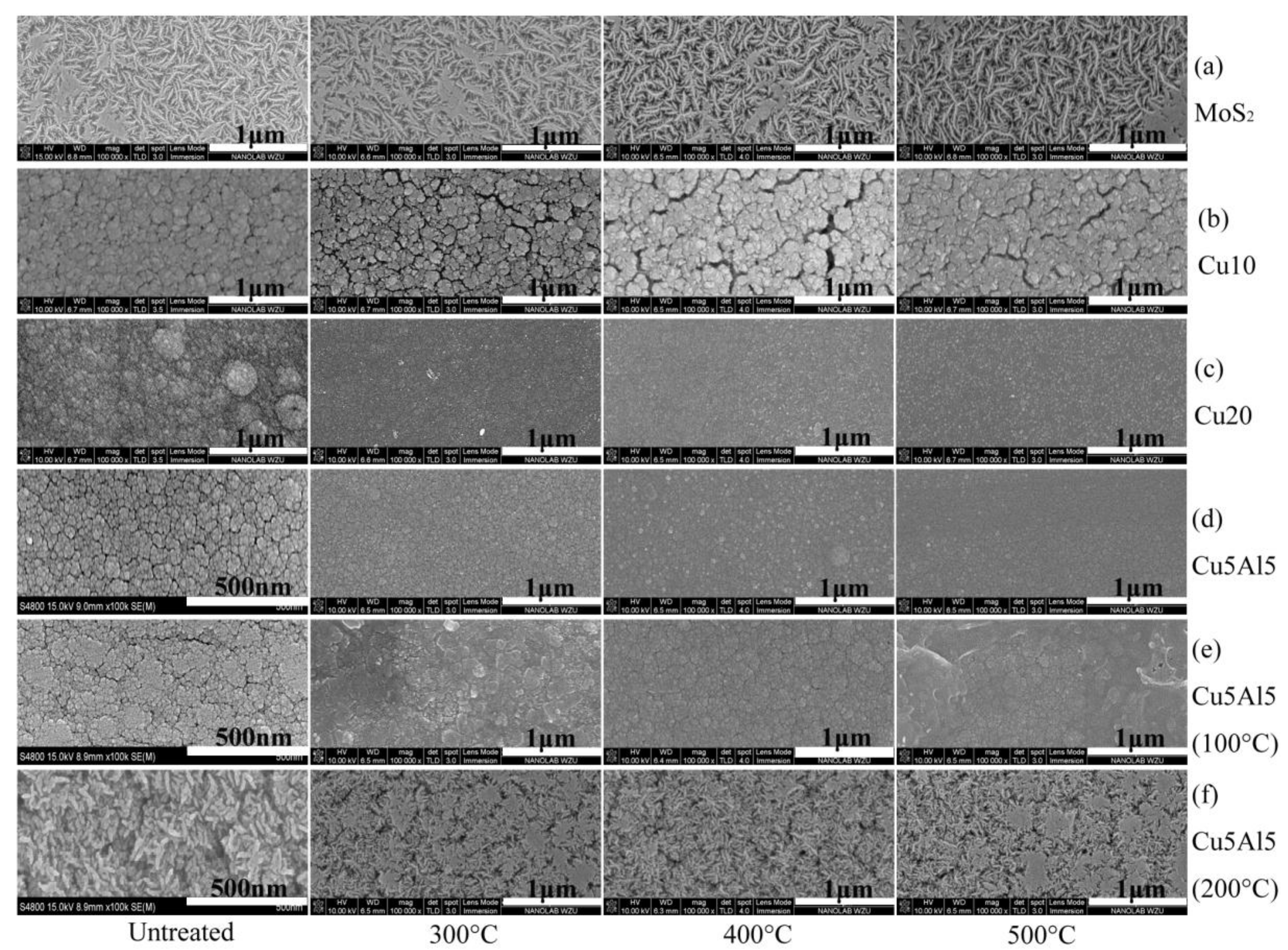
Figure 3.
EDS spectrum corresponding to the (a) Cu10; (b) Cu20; and (c) Cu5Al5.
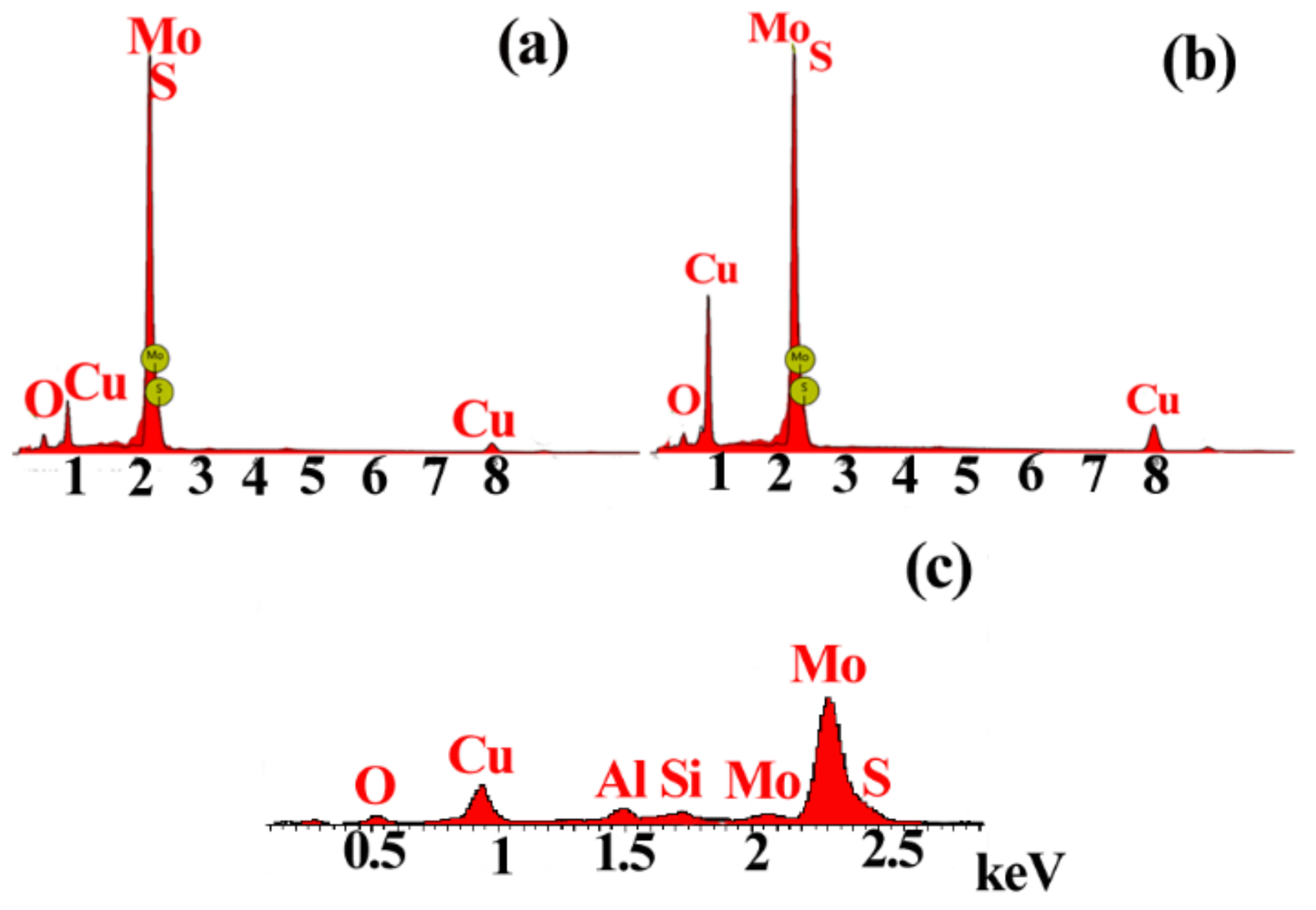
Figure 4.
XRD spectrum of Cu/MoS2 and Cu-Al/MoS2 composite coatings.
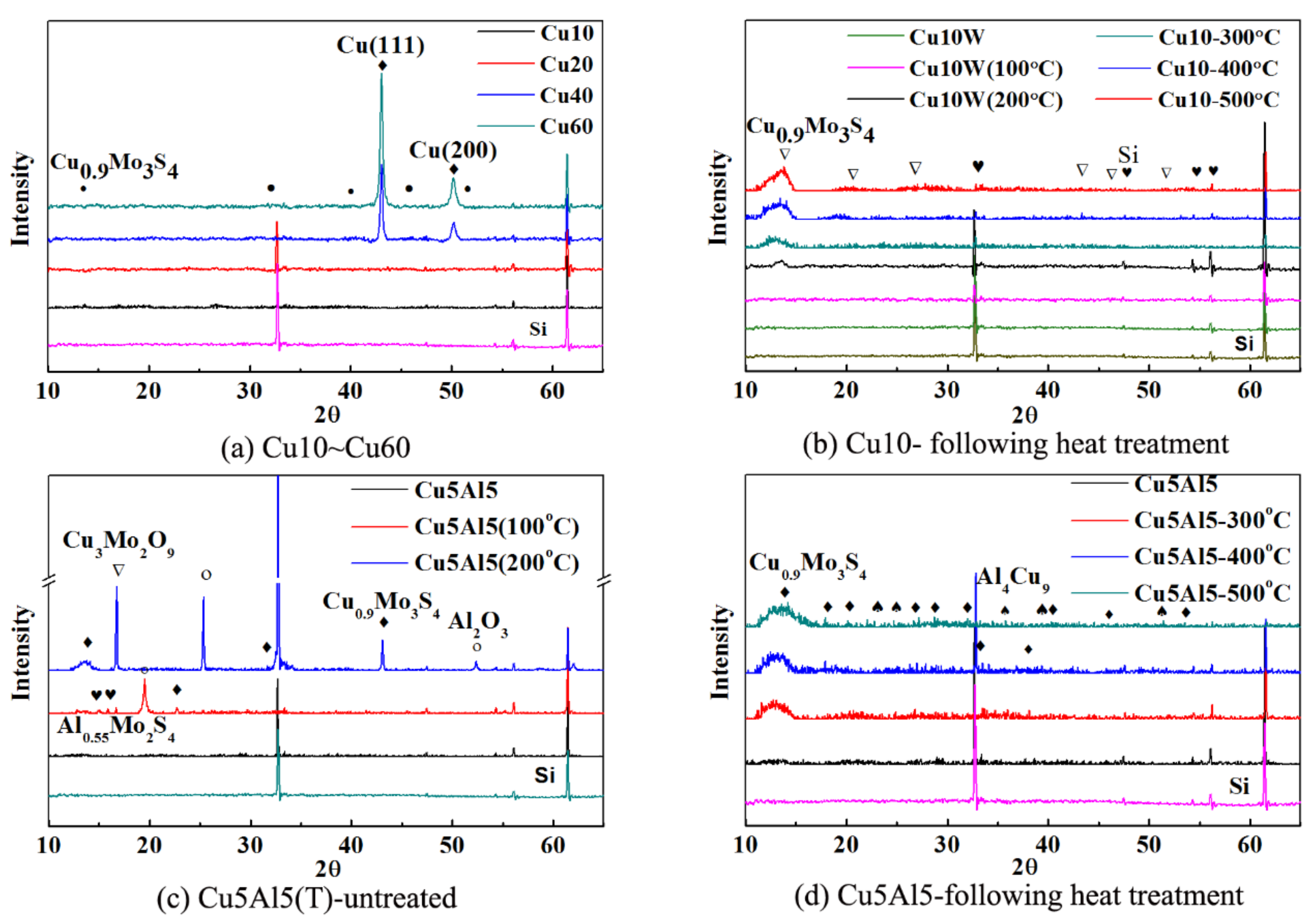
Figure 5.
Friction coefficients of Cu/MoS2 composite coatings at various heat treatment temperatures.
Figure 5.
Friction coefficients of Cu/MoS2 composite coatings at various heat treatment temperatures.

Figure 6.
Friction coefficients of the Cu5Al5 composite coatings at various heat treatment temperatures.
Figure 6.
Friction coefficients of the Cu5Al5 composite coatings at various heat treatment temperatures.
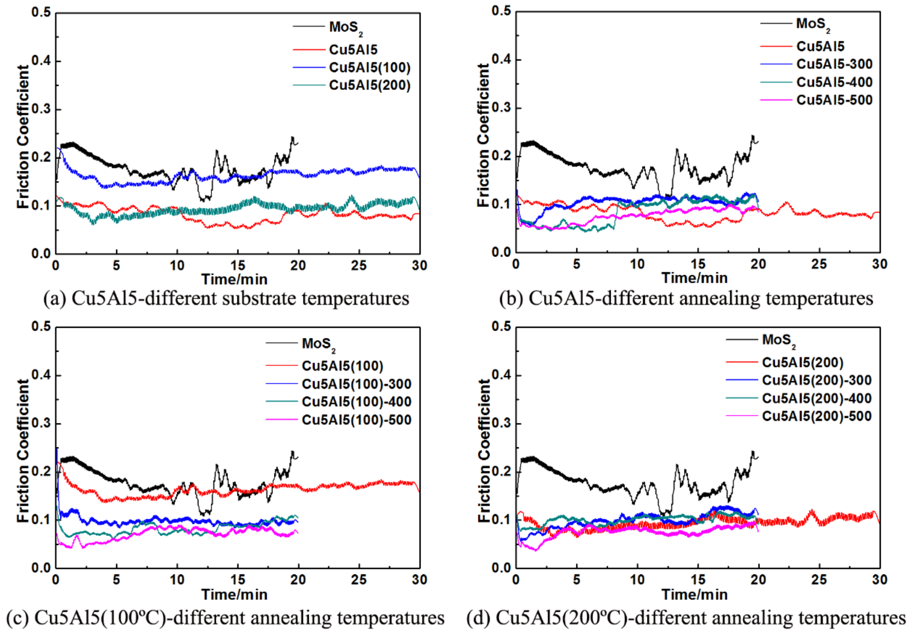
Figure 7.
OM micrographs of MoS2-based composite coating wear tracks following heat treatment.

Figure 8.
Scratches of (a) Cu10; (b) Cu20; (c) Cu5Al5; (d) Cu5Al5 (100 °C); (e) Cu5Al5 (200 °C) coatings annealed at 500 °C.
Figure 8.
Scratches of (a) Cu10; (b) Cu20; (c) Cu5Al5; (d) Cu5Al5 (100 °C); (e) Cu5Al5 (200 °C) coatings annealed at 500 °C.

Figure 9.
3D reconstructions and SEM surface morphologies of wear tracks in coatings annealed at 500 °C.
Figure 9.
3D reconstructions and SEM surface morphologies of wear tracks in coatings annealed at 500 °C.

Figure 10.
EDS analysis of worn surfaces. (a) Cu10; (b) Cu5Al5 annealed at 500 °C.
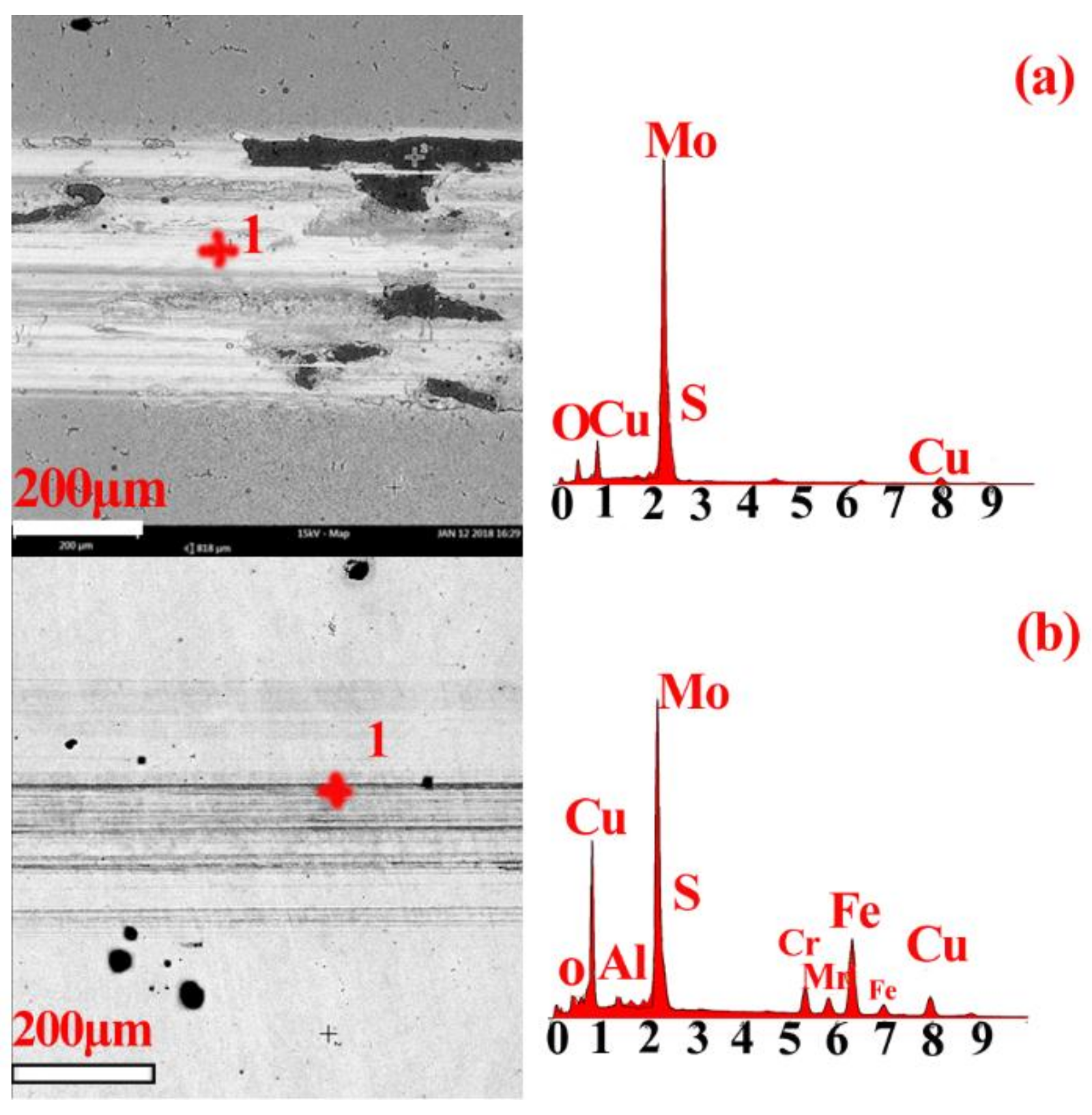
Figure 11.
Atomic percentage of oxygen in wear tracks of the coatings annealed at 400 °C and 500 °C.
Figure 11.
Atomic percentage of oxygen in wear tracks of the coatings annealed at 400 °C and 500 °C.

Figure 12.
Wear rate of MoS2-based coatings at various heat treatment temperatures.


Table 1.
Parameters for fabrication of MoS2-based composite coatings.
| Sample No | Target Power/W | Substrate Heat Temp./°C | ||
|---|---|---|---|---|
| MoS2 | Cu | Al | ||
| Cu5 | 100 | 5 | 0 | Unheated |
| Cu10 | 100 | 10 | 0 | Unheated |
| Cu20 | 100 | 20 | 0 | Unheated |
| Cu40 | 100 | 40 | 0 | Unheated |
| Cu50 | 100 | 50 | 0 | Unheated |
| Cu60 | 100 | 60 | 0 | Unheated |
| Cu10(100 °C) | 100 | 10 | 0 | 100 |
| Cu10(200 °C) | 100 | 10 | 0 | 200 |
| Cu5Al5 | 100 | 5 | 5 | Unheated |
| Cu5Al10 | 100 | 5 | 10 | Unheated |
| Cu10Al5 | 100 | 10 | 5 | Unheated |
| Cu10Al10 | 100 | 10 | 10 | Unheated |
| Cu5Al5(100 °C) | 100 | 5 | 5 | 100 |
| Cu5Al5(200 °C) | 100 | 5 | 5 | 200 |
Table 2.
Quantitative results of Cu/MoS2 coatings elemental analysis, determined through EDS.
| Composite Coating | Cu/at.% | NS/NMo |
|---|---|---|
| MoS2 | 1.50 | |
| Cu5 | 7.80 | 0.78 |
| Cu10 | 9.57 | 1.18 |
| Cu20 | 25.13 | 1.34 |
| Cu40 | 40.69 | 1.42 |
| Cu50 | 46.21 | 1.50 |
| Cu60 | 47.99 | 1.78 |
| Cu10 (100 °C) | 28.55 | 1.30 |
| Cu10 (200 °C) | 35.50 | 1.76 |
Table 3.
Quantitative results of Cu-Al/MoS2 composite coatings elemental analysis, determined through EDS.
Table 3.
Quantitative results of Cu-Al/MoS2 composite coatings elemental analysis, determined through EDS.
| Composite Coating | Cu/at.% | Al/at.% | NCu/NAl | NS/NMo |
|---|---|---|---|---|
| MoS2 | 1.5 | |||
| Cu5Al5 | 24.53 | 10.97 | 2.24 | 1.54 |
| Cu5Al10 | 16.26 | 8.78 | 1.85 | 1.92 |
| Cu10Al5 | 28.05 | 4.07 | 6.88 | 1.91 |
| Cu10Al10 | 27.07 | 5.98 | 4.52 | 1.72 |
| Cu5Al5 (100 °C) | 10.95 | 5.63 | 1.94 | 1.39 |
| Cu5Al5 (200 °C) | 11.42 | 3.44 | 3.32 | 1.58 |
© 2018 by the authors. Licensee MDPI, Basel, Switzerland. This article is an open access article distributed under the terms and conditions of the Creative Commons Attribution (CC BY) license (http://creativecommons.org/licenses/by/4.0/).
Share and Cite
MDPI and ACS Style
Cao, M.; Zhao, L.; Wu, L.; Wang, W. Tribological Properties of New Cu-Al/MoS2 Solid Lubricant Coatings Using Magnetron Sputter Deposition. Coatings 2018, 8, 134. https://doi.org/10.3390/coatings8040134
AMA Style
Cao M, Zhao L, Wu L, Wang W. Tribological Properties of New Cu-Al/MoS2 Solid Lubricant Coatings Using Magnetron Sputter Deposition. Coatings. 2018; 8(4):134. https://doi.org/10.3390/coatings8040134
Chicago/Turabian StyleCao, Ming, Lan Zhao, Libin Wu, and Wenquan Wang. 2018. "Tribological Properties of New Cu-Al/MoS2 Solid Lubricant Coatings Using Magnetron Sputter Deposition" Coatings 8, no. 4: 134. https://doi.org/10.3390/coatings8040134
Note that from the first issue of 2016, this journal uses article numbers instead of page numbers. See further details here.