Effect of Reaction Conditions on the Surface Modification of Cellulose Nanofibrils with Aminopropyl Triethoxysilane


1
Biorefinery Processes Research Group, Faculty of Engineering Gipuzkoa, University of the Basque Country UPV/EHU, Plaza Europa, 1. 20018 Donostia, Spain
2
Institute of Wood-Based Products and Technologies, University of Sopron, Bajcsy-Zs. E. u. 4, 9400 Sopron, Hungary
*
Author to whom correspondence should be addressed.
Coatings 2018, 8(4), 139; https://doi.org/10.3390/coatings8040139
Submission received: 7 March 2018
/
Revised: 9 April 2018
/
Accepted: 11 April 2018
/
Published: 13 April 2018
(This article belongs to the Special Issue Surface Modification of Cellulose Fibres)
Abstract
:Nine different surface modifications of cellulose nanofibrils (CNF) with 3-aminopropyl triethoxysilane (ATS) by using three different solvent systems (water, ethanol, and a mixture of both) were investigated. The effect of reaction conditions, such as silane to cellulose ratio and solvent type were evaluated to determine their contribution to the extent of the silane modification. Nanofibril properties were evaluated by infrared spectroscopy, powder X-ray diffraction, surface free energy, thermogravimetry, 13C and 29Si nuclear magnetic resonance, and electronic microscopy. The influence of the solvent in the solvolysis of the silane was reflected in the presence or absence of ethoxy groups in the silane. On the other hand, whereas the surface modification was increased directly proportionally to silane ratio on the reaction, the aggregation of nanofibrils was also increased, which can play a negative role in certain applications. The increment of silane modification also had substantial repercussions on the crystallinity of the nanofibrils by the addition of amorphous components to the crystalline unit; moreover, silane surface modifications enhanced the hydrophobic character of the nanofibrils.
1. Introduction
Since the first discovery of cellulose defibrillation in 1983 [1], new methods to achieve nano-scaled polycrystalline cellulose units have attracted numerous researchers into the world of carbohydrates. At present, this includes not only the traditional polycrystalline microfibrillated cellulose (or cellulose nanofibrils), but also nanocrystalline cellulose, both obtained from native cellulose extracted either from the plant wall or other sources, such as bacterial cellulose, enzymatic cellulose, or even tunicates. Carbohydrate research was later expanded to other cellulose polymorphs (celluloses Iα and Iβ, and cellulose derivatives such as celluloses II and III and celluloses IV and V), as well as other carbohydrates, such as chitin and even hemi/holocelluloses. The interest in such carbohydrate polymorphs is basically due to three aspects: price, mechanical properties, and chemical grafting potential [2]. The amount of free hydroxyl groups on cellulose surface enhances the feasibility of chemically attaching active compounds for multiple functions in a diverse range of applications. These include biomedical, bioimaging, nanocomposites, gas barrier films, and more recently, multifunctional materials; which in addition can be biodegradable and can easily meet the most strict polymer regulations because of their natural origin and the biodegradability lifespan, which is considerably lower than other products [3].
However, one of the reasons why nanocellulose has found reticence to its wider use is its poor interfacial adhesion [4] and its difficulty to disperse in non-polar solvents or non-polar polymeric matrices [5,6]. Consequently, the modification of nanocellulose to overcome this phenomenon prior to its further use is of high interest. Within this research field, several reports have emerged focused on the surface modification of nanocellulose with quite pleasant results. In composite materials, two solutions have been proposed, either modifying the surface of the fibers or that of the matrix [7]. The surface of cellulose nanoparticles can be modified by various methods, by using chemical modification to form covalent bonds between cellulosic substrates and the grafting agent, or by the physical interaction, or adsorption, of molecules on the macromolecular surface. The identification of the optimum surface modification is an important aspect of the quality of nanocellulose-based composites. On this basis, it the verification of the treatment conditions should be considered at first instance, during which the structure of the cellulose should not be damaged. Also, the further optimization of qualities such as impact resistance, modulus of elasticity, and strength to breakage, can be achieved by controlling the bonding degree of the structural elements and matrix in the composite [6,8].
The use of organosilanes to achieve surface modification of cellulose fibers has proved to be a good method to render nanocellulose surface hydrophobic and to improve matrix-filler interactions for cellulose-reinforced composites by serving as a coupling agent, or even giving stability in nonpolar environments as well as hydrophobic functionality [9,10,11], either as a suspension in different solvents or added as bulk into a polymeric matrix [12,13,14]. Most of the widely used organosilanes are silicon chemicals that possess a hydrolytically sensitive center that can react with substrates to form stable covalent bonds, commonly with three hydrolysable substituents and one organic substituent that alters the physical interactions of treated substrates. The general formula of an organosilane can be written as follows:
RnSiX(4−n)
In which R is the non-hydrolysable organic radical that possesses a determined functionality; X is a hydrolysable functional group, which is involved in the reaction with the substrate; hydrolysable groups are typically alkoxy, acyloxy, amine, or chlorine. The most common alkoxy groups are methoxy and ethoxy, which give methanol and ethanol as byproducts during coupling reactions [15,16,17]. Surface modification of cellulose is started with a solvolysis, prior to the surface reaction [18], which is followed by a reaction between silanol groups and OH groups of cellulose at high temperature [6].
Surface silylation of NFC from bleached softwood pulp using chlorodimethyl isopropylsilane was investigated by Andresen and collaborators [19]; they noted that after silane modification, NFC could be dispersed in a polar solvent. They found that derivation became negligible because of the competitive hydrolysis of silane agent when the molar ratio of silane agent of repeating glucose unit turned into lower than 3:1. Goussé et al. in 2004 [9] studied the rheological properties of mild silane modification of NFC by isopropyl dimethylchlorosilane. The morphology of these nanofibrils was similar to un-derivatized ones and produced stable suspensions without fluctuation. The suspension showed shear thinning influences and thickening characteristics but had no noticeable yield stress point. Previous works by this group have shown that the use of acidic water-based media to hydrolyze silane, resulting in strong and stable silane grafting which has been applied in composite materials [20,21], however, to what extent the solvent influences the grafting has not been disclosed.
In this work, nine different silane surface modifications were performed on nanofibrillated cellulose. The selected reagent was an organosilane containing an amino group as a non-hydrolysable group: 3-aminopropyl triethoxysilane. Modifications were performed in three different aqueous systems consisting of 100% water, 50:50 water/ethanol, and 100% ethanol media and the amount of silane was tested in three different ratios. The surface modifications were analyzed with chemical and physical characterization techniques to assess the influence of the reaction media and the silane to cellulose ratio in the performance of the surface modification.
2. Materials and Methods
Cellulose nanofibrils used in this work were obtained from blue agave (Agave tequilana) bagasse fibers digested from a Total Chlorine Free bleached pulp (organosolv pulping) as previously reported by this group [22]. 3-aminopropyl triethoxysilane was provided by Alfa Aesar GmbH (Lancashire, UK). All other components were used at laboratory conditions and provided by Sigma-Aldrich (St. Louis, MO, USA).
Cellulose nanofibrils with an average length of 607 ± 85 nm and an average width 68 ± 22 nm were modified with 3-aminopropyl triethoxysilane (ATS) solution inside a plastic beaker to avoid ATS reactions with the glass surface. The use of distilled water is not necessary, but water containing fluoride ions must be avoided, however; for this work, distilled water was used for the whole process.
Traditionally, silanes are diluted in aqueous alcohol solutions prior to applying, with a conventional ratio of 95% ethanol and 5% water, which is further adjusted to a pH of 4.5–5.5 with carboxylic acids as catalysts [23]. The recommended silane concentration is 2% v/v of the aqueous solution. For the present work, the neat silane ratio to cellulose nanofibrils was 1:1, 2.5:1, and 5:1 w/w which corresponds to approximately 0.5% to 2.0% silane concentration in the solution. ATS solution was first diluted in ethanol, ethanol-water (50/50) or water; pH was lowered by dribbling acetic acid with constant stirring. Once the pH was stabilized at 5.5, CNF were dispersed in ethanol, ethanol–water (50/50), or water at approximately 3 wt % and added to their corresponding silane solution. The mixture was stirred with a Silent crusher homogenizer at 2000 rpm during 5 min and left at room temperature for another 45 min; during which solvolysis and silanol formation occur. The slurry was vacuum-filtered with a 0.22 μm nylon membrane and washed with the same aqueous media used for the modification to wash unadsorbed silanes. Then cellulose-silane gels were stabilized to a 3 wt % concentration, which was stored at 3 °C in plastic containers for further analysis. The completion of the organosilane–CNF reaction requires curing at ~110 °C; this was performed over 5–10 min as only heat can induce a proper chemical modification to form covalent bonding between adsorbed silanes and CNF [24], but preserving the nanocellulose–silane solution in the aqueous state allows better dispersion and better processing conditions for composite elaboration. For solid-state analysis of the different nanocelluloses, the gel was oven cured until no solvent was left and was then rinsed two times with ethanol, then pressed to form films with a hydraulic press at 100 °C [25]. Table 1 presents the reaction conditions for the different modifications.
Atomic force microscopy (AFM) images were obtained with a NanoScope IIIa, Multimode TM-AFM from Digital Instruments-Veeco scanning probe microscope (Plainview, NY, USA) operating in tapping mode equipped with an integrated silicon tip cantilever with a resonance frequency of 300 kHz. Single fiber images were captured in height mode. For films, AFM images were collected in 2D phase mode.
Infrared spectra were recorded on a Perkin-Elmer Spectrum Two FT-IR Spectrometer (Waltham, MA, USA) equipped with a Universal Attenuated Total Reflectance accessory with internal-reflection diamond crystal lens. The defined range was from 4000 to 400 cm−1 and the resolution 4 cm−1. For each sample, 30 scans were recorded and averaged.
TGA (definition) essays were carried out in a TGA/SDTA 851 Mettler Toledo instrument (Greifensee, Switzerland) according to standard test methods [26]. This was done under nitrogen atmosphere (20 mL min−1) from 25 to 800 °C at 10 °C min−1. The thermal decomposition temperature was taken as the onset of significant weight loss after the initial moisture loss.
X-ray powder diffraction was measured to analyze the contribution of amorphous silanes in the structure of nanocrystalline cellulose. Diffraction scatters were collected with a Panalytical Phillips X’Pert PRO multipurpose diffractometer (Almelo, the Netherlands), using monochromatic Cu Kα radiation (λ = 1.5418 Å) in the 2θ range from 5° to 70° with step size of 0.026 at room temperature.
NMR spectrometry for 13C and 29Si were performed using a Bruker 500 MHz spectrometer (Billerica, MA, USA) at 250 MHz of frequency at room temperature. The spectrum was recorded with cross-polarization and magic angle spinning.
Contact angle measurements were performed with a DataPhysics (Filderstadt, Germany) video-based measurement contact angle system OCA20 with a software controlled dosing volume using water, formamide, and diiodomethane to determine surface free energy following the Owens, Wendt, Rabel, and Kaelble (OWRK) method [27,28,29].
3. Results
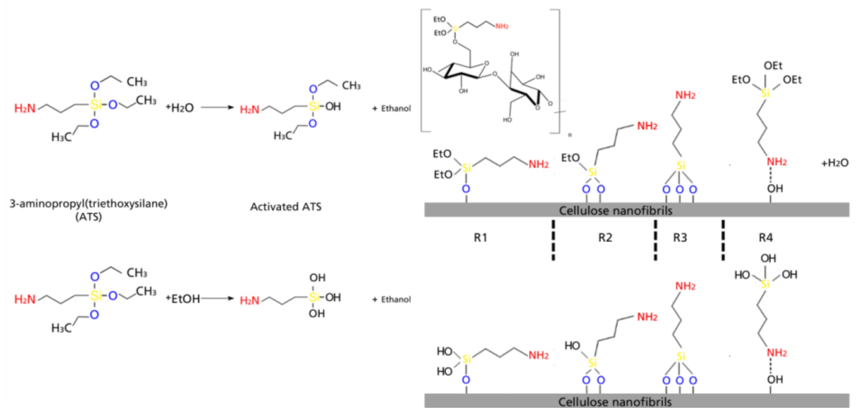
Silane surface modification of CNF occurs in four steps which basically involve a chemical grafting on the hydroxyl groups on the surface of cellulose chains (in this case CNF consisting basically of cellulose Iβ) via reaction with silanol groups. In the case of ATS, the non-hydrolysable group would be the aminopropyl chain. The first stage of the modification consists in a solvolysis of the ethoxy groups, after which a reactive silanol group is formed. After hydrolysis, the following reactions can occur either sequentially or simultaneously: condensation to oligomers with other silanol groups to form siloxane linkages; the oligomers then form hydrogen bonds with the –OH groups of the cellulose, stable condensation products are also formed with other oxides form stable bonds with SiO; drying or curing at temperatures ranging between 80 °C and 110 °C (in the present work kept constant at 105 °C), during which a covalent linkage is formed with the hydroxyl groups of cellulose with concomitant loss of water. In the present work, the different types of silane-cellulose couplings are presented in Scheme 1; according to literature, there are 4 main reactions that can occur at the interface [18,30]. R1: silicon units of the organosilane may bond uniquely by one to the cellulose surface; the two remaining silanol groups are present, either bonded to other silicon atoms or in free form. R2: two silylether bonds reacted with cellulose. R3: aminosilane reacted onto cellulose with three silylether bonds. R4: aminosilane is polymerized [31]. At the interface, there is only one bond of the organosilane silicon on the cellulose surface. In any of the first three proposed reactions, the aminopropyl group remains available for covalent reaction or physical interaction with other phases. In case of ethanol-based silanes, silanes were fully activated with hydroxyl groups, but with no hydrolysable functional group.
Solid-state NMR analysis was done studying two nuclei (13C and 29Si) with magic angle spinning and cross polarization (CP-MAS NMR). Figure 1 shows the 13C NMR analysis for the modified celluloses: (a) corresponds to the resonances of the C4 carbon of cellulose; (b) to the C6 carbon of cellulose; (c) presents the 13C spectra in the range of the chemical shifts corresponding to ATS carbons; (d) presents the different carbon contributions of the modified CNF; and (e) shows the corresponding identification of each carbon; moreover, in the Supplementary Material, Figure S1 presents the NMR spectrum of ATS and Figure S2 presents the full NMR spectra of CNF and modified CNF samples. In the 13C resonances of the silane (Figure S1, Supplementary Material), two main aspects can be appreciated: chemical shifts corresponding to carbons Ca and Cd, which correspond to the triethoxy hydrolysable group of the ATS and carbons Cb, Cc, and Ce, which in the literature have been identified as: αCH2(Si–CH2), βCH2(CH2), and γCH2(CH2–NH2) resonances of the aminopropyl groups of the ATS [32,33].
There are perceptible differences in the region of chemical shifts that are characteristic to cellulose (110–60 ppm); changes include a slight reduction of the C4 amorphous region (85–80 ppm) in the case of E1, E2, and E5; while in M1 and W1, W2, and W5, there is an increase in the C4 amorphous region with a slight increase in the C4 crystalline region (90–86 ppm), which means that when the reaction is done in water, there is a tendency to graft oligomers in this position. Such increases in the amplitude of signals are also present in the C6 chemical shifts corresponding to the amorphous region (58–64 ppm) presenting the same correlation (increase in M1, W1, W2, and W5). The most visible phenomena appreciable from 13C NMR analysis is the complete lack of resonances in the ATS 13C chemical shifts for CNF modified in ethanol media (E1, E2, and E5), while in the case of modifications carried out in water media (W1, W2, and W5) the overlapped signal of the βCH2 (c) and the CH3 (d) is considerably more prominent. In case of 13C NMR chemical shifts characteristic to ATS (55–10 ppm), it can be appreciated that for water-based modifications, the reactivity of silane–cellulose interactions is higher in W1, W2, and W5, as well as M1 and M2, and with smaller amplitude in M5, there are higher amplitudes for the silane chemical shifts corresponding to the Ca and Cd carbons of the silane at around 55 and 22 ppm respectively, which means that ethoxy groups are still present in the silane–CNF network. For E1, E2, and E5, the chemical shifts corresponding to ethoxy carbons are not present as during reaction, ethanol is produced from hydrolyzed silanes as a byproduct and during casting such ethanol is evaporated, however, the signals corresponding to propyl chains which are Cb at ~42, Cc at ~24.5, and Ce at ~10.5 ppm [34,35] are almost imperceptible, which is theoretically the non-hydrolysable organic substituent which may have been cleaved from the C4 and C6 crystalline regions.
Figure 2a shows the normalized 29Si resonances of modified CNF, the differences between the samples are not visually appreciable as they only show the presence of the Si chemical shifts of the silane, however, the fact that all of them present resonances in the 29Si NMR, means that silicon is present in all of the CNF networks. 29Si NMR shows two peaks which correspond to single SiO and Si–O–Si silicon linkages [36]. Reported silicon-based tetrahedrons containing oxygen and organic “R” groups have highlighted differences between binary, ternary, and quaternary structures [36,37,38]. T structures correspond to three oxygen-one organic group tetrahedrons, and four T types have been reported, which are enumerated as T0, T1, T2, and T3. T1 corresponds to dimers attached by the chain end and are between 40 and 55 ppm, T2 are oligomers in linear linkage with shifts between 55 and 65 ppm and T3 corresponds to a 3D oligomer structure with shifts between 65 and 75 ppm, this is commonly the most abundant structure In case of the modifications performed, the most distinctive result of this analysis is the higher contribution of dimmers in ethanol-based reactions, T1 structure had an average occurrence of 2% in ethanol based reactions, while for ethanol–water, it was 0.3% and 0.8%. For water systems Linear oligomeric structure T2 had similar occurrence throughout the different systems, being 22% in ethanol, 20% in ethanol–water, and 18% water. However, 3D oligomeric structures (T3) had an occurrence of 75% in ethanol, 79% in ethanol–water, and 81% in water. The total contribution of each structure can be seen in Figure 2b.
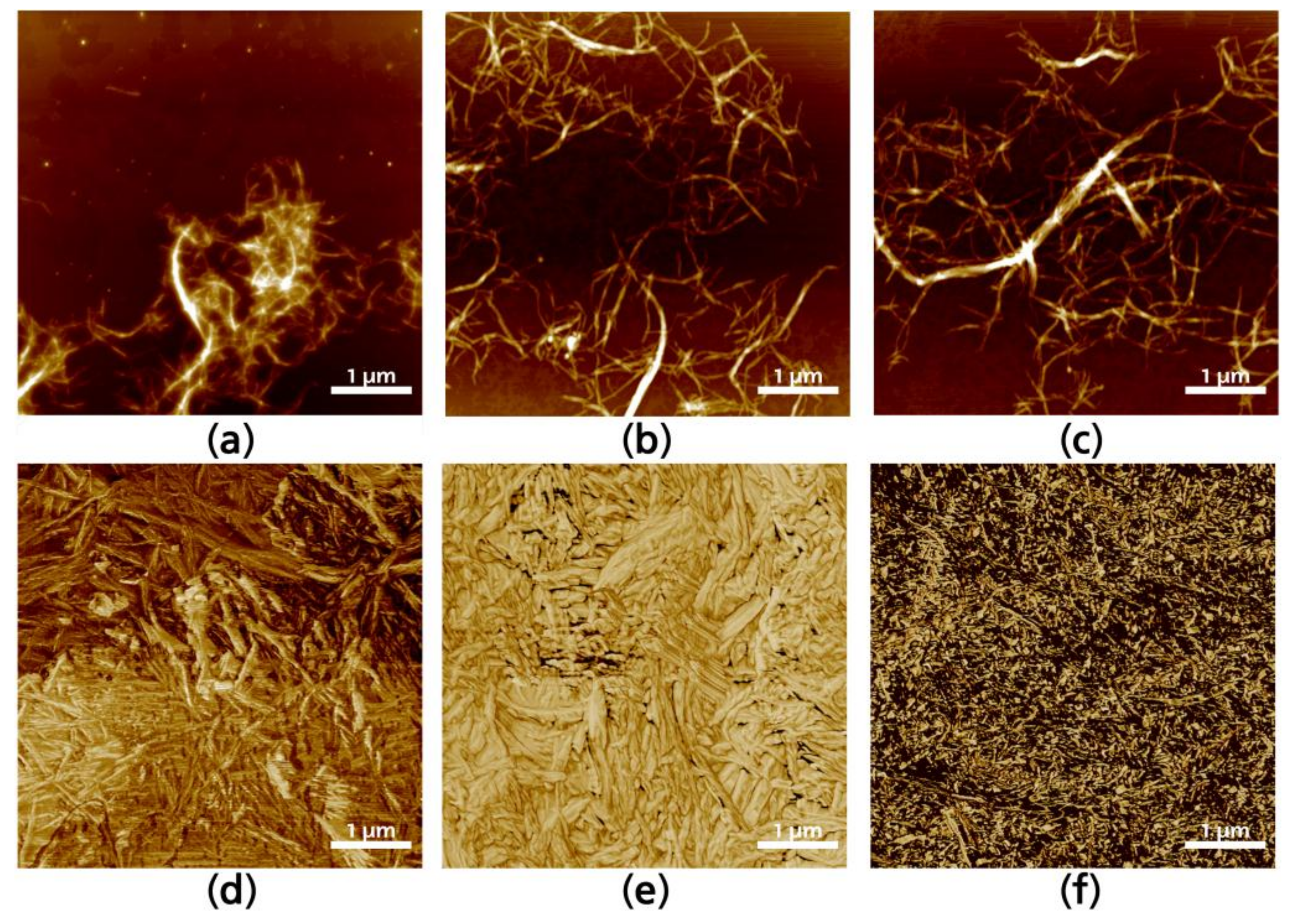
To analyze individual fibrils, cured CNF were redispersed in the media in which they were elaborated until a 0.5 wt % concentration was achieved, and then sonicated during 5 min to disperse entanglements. Figure 3 shows selected redispersed fibrils after silane modification. The interaction of silanes in water media (Figure 3a) generates more hydrolyzed silanol units, which makes it more reactive to form covalent bonds with cellulose free hydroxyl groups. Visually, the formation of agglomerations between CNF can be observed in Figure 3a, as well as the halo formed around the fibrils, which is not present in the ethanol media (Figure 3c) modified CNF neither in the ethanol–water media (Figure 3b). Surface topographies of modified CNF give further information regarding the interactions between fibrils after the solvent is evaporated. The assembly is anisotropic, as is common in CNF solvent-casted films, with significant differences between the fibrils modified in aqueous or ethanol media. Figure 3d–f presents AFM topographies of selected solvent-casted films which correspond to the CNF containing the highest yield of silanes in the solution (W5, M5, and E5). This was done as the higher amount of silane would make it easier to appreciate changes in the CNF topography. There is an unquestionable difference between CNF modified in aqueous media regarding those modified in alcoholic media. The first presenting a broader and stiffer structure i.e., CNF tend to be straighter and with wider diameters, as it can be appreciated in Figure 3d,e. On the other hand, when the reaction was performed in ethanol media, the way in which silanes are attached to the CNF and the modified CNF interact with each other is significantly changed and individual fibrils are narrower, having entanglements that are more visible (Figure 3f).
The infrared spectra were analyzed to identify ATS. Figure 4 presents the ATR-FT-IR spectra of native and modified CNF with magnified regions for a better identification of distinctive bands. Full FT-IR spectra (Figure S3), as well as FT-IR spectrum of ATS (Figure S4), are shown in the Supplementary Material. ATS-modified nanocelluloses present changes in the behavior of bands between 3600 and 3000 cm−1 because of the modification of the free hydroxyl present in native cellulose. This band tends to reduce its intensity, as the hydroxyl groups are less available as they have reacted with the silanol groups; highest reductions in this band are visible in case of E1, M1, and W2, while W1 and E5 have more intense signals in the 3600–3000 cm−1 band. The band between 3000 and 2600 cm−1 corresponds to the C–H vibrations. While M5 has the most prominent signal in this band, samples containing low silane (E1, M1, and W1) present a rather flat signal, with M2, E5, and M2 presenting slightly higher signals. This can be explained through the solvolysis of the ethoxy groups in the aqueous media, as well as the number of ethoxy groups of the silane reacting with the free hydroxyl groups present in the surface of the cellulose, as shown in the proposed model in Scheme 1. The IR spectra at 1800–800 cm−1 of the different nanocelluloses were used to estimate the effect on the binding of the aminosilane with the cellulose. The band at 1750 cm−1 proved to be characteristic for the vibrations of the carboxyl group C=O. The IR spectra contained bands at 1600–1580 cm−1, characteristic of deformation vibrations of N–H coming from the I amine group in the ATS [24,39]. Moreover, the IR spectra contained bands at 1550 cm−1, characteristic of amino scissoring bending vibration from the amine group in the silane. The presence of these bands in the IR spectra of the modified cellulose also confirmed the stable bonding of the silane preparations with the cellulose; the band at 1550 cm−1 presents significant signals for M2, W5, and E5. In the 1300–1000 cm−1 band, there is an increase in the intensity because of the chemisorbed ATS related to the Si–O–Si bonding [40]. In the spectra of the modified cellulose with the ATS, there was also a band at 690 and 650 cm−1, characteristic of vibrations of Si–C and Si–O groups, respectively, coming from the ethoxy group in the organosilane. Furthermore, in the case of modifications performed with the highest silane content (W5, M5, and E5) Si–Si bonding vibrations can be perceived around the band of 600 cm−1 which implies that there are silanes reacting with each other. ATR FT-IR analysis confirmed that reactions between the cellulose and organosilane occurred, as discussed earlier.
Thermal stability and degradation profile were analyzed by thermogravimetry. Figure 5 shows selected mass-loss thermogravimetric curves as well as derivative thermogravimetric curves of raw and modified CNF. During thermal degradation of fibrils, the two main aspects to consider are the mass loss at key temperatures, which correspond to the mass changes of a sample due to degradation of determined components as a function of the temperature, time, and atmosphere under which the thermogravimetric analysis is performed. The other aspect is the final residue which corresponds to char and inorganic compounds, mainly to SiO2 [33]. With lower silane yield, there is a considerable variation between the different samples, with W1 having the lowest residue at 800 °C, while M1 had the highest residue. This can be due to the water–ethanol solvolysis and the pyrolysis of unreacted carbohydrates. As it was stated in the reaction dynamics, the solvolysis of ethanol and its further evaporation leaves the modified cellulose with the higher mass content of the inorganic material, while the lesser solvolysis of CH3 groups is related to a higher content of combustible material that is degraded faster. In case of M1 and M5 samples, the thermal degradation is retarded, which makes them the best performing CNF modification for thermal degradation retardation; the final residue is higher in M samples than in E or W, which means that the % content of inorganic matter is higher, particularly with lower silane content. However, differences between the final residues between CNF modified with higher silane content are generally not significant, regardless of the solvent used. As proposed by Fathi et al. [41] and Rachini et al. [42], TGA analysis can be used to determine the amount of silane grafted to the CNF samples by correlating the final residue of the neat and grafted samples after 400 °C, which corresponds to the full degradation of cellulose. This can be achieved by the following equation:
where Sig is the grafted silane, expressed in millimoles per gram of CNC, W105–400 corresponds to the differences between the normalized weights of the samples at 105 °C (samples without water content) and 400 °C (samples after cellulose degradation); and MwATS is the molecular mass of the hydrolyzed silane. The results (Figure 5c) show that silane grafting was more effective in mixed media, with water having lower values in general. The maximum of grafted silane was 2.8242 mmol g−1 for M5, 2.1428 mmol g−1 for W5, and 2.3856 mmol g−1 for E5. Reactions having a lower silane-to-cellulose ratio, which is more common in the bibliography, have 0.4164 mmol g−1 for W1, 0.9122 mmol g−1 for, and 1.6896 mmol g−1 for M1. In general, the presented results are higher than those reported in the above-mentioned works, as the media and the avoidance of long Soxhlet extractions allows weak bonding to be maintained on the CNF surface.
Sig = (W105–400/MwATS) × 1000
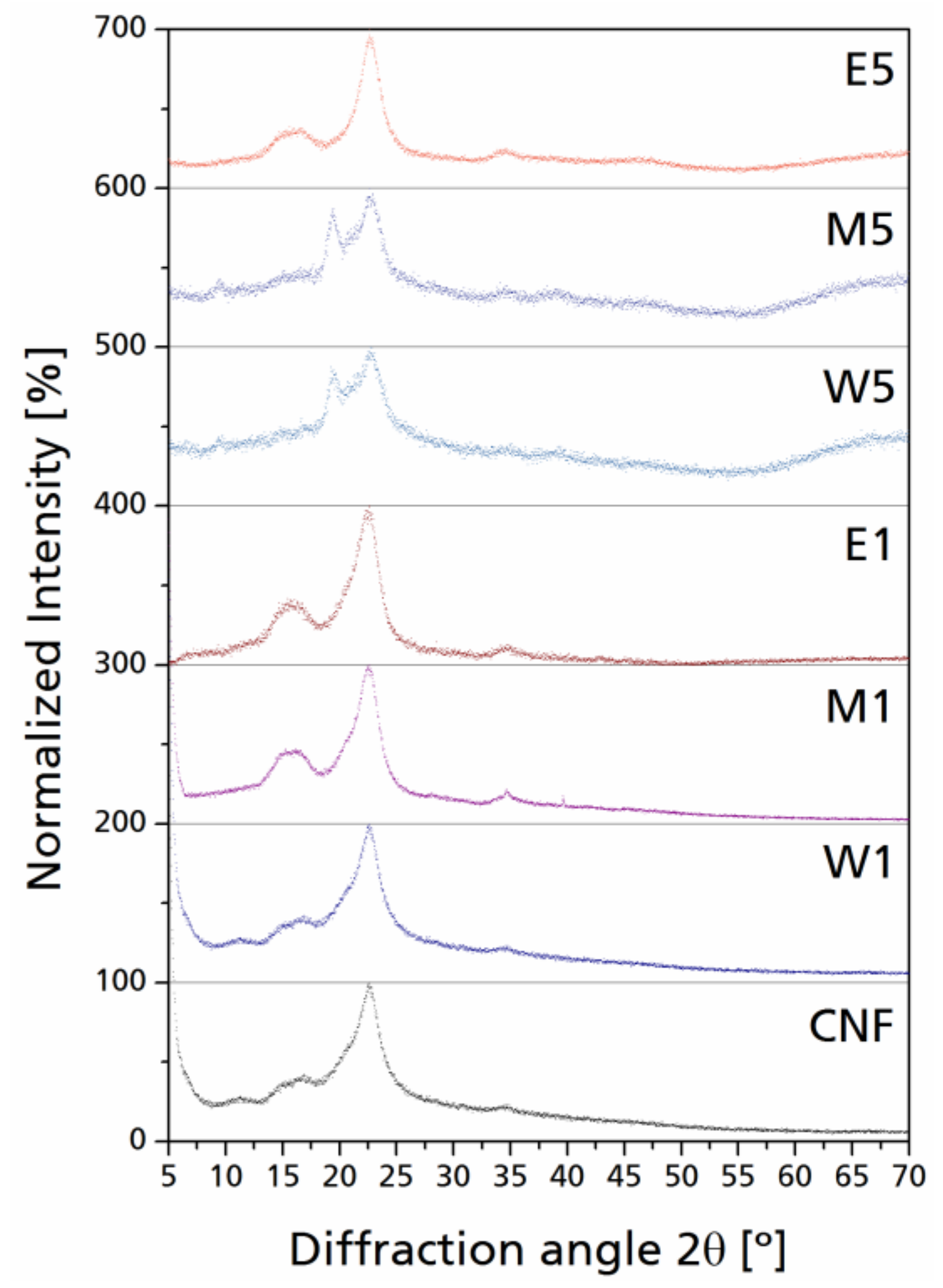
Cellulose is a paracrystalline polymer composed of crystalline regions attached to amorphous domains [43]. After grafting of ATS, the surface modification performed in each sample generated a new amorphous region around the paracrystalline cellulose by covalent bonding with the hydroxyl groups present in the exterior chains of the molecular wall as well as through oligomer interactions between silanes. In X-ray diffractograms, the contribution made by amorphous silanes in the structure of the nanocelluloses can be easily appreciated when the silane to cellulose ratio is higher.
In general, a slight bump can be observed as a result of the addition of amorphous materials to the paracrystalline cellulose. In Figure 6, the normalized XRD scatters are presented for selected modified CNF. The appearance of new peaks at 2θ ~20° with low intensity and high internal breath can be seen, which can be related to the diffraction corresponding to the 110 lattice plane of cellulose, which corresponds to an increase on the periodic arrangement in such plane; this is less visible in CNF with lower silane yield (W1, M1, and E1).
Peaks with higher intensities and narrow integral breath for the diffraction corresponding to the 200 lattice planes can also be observed; this phenomenon can be related to some of the un-oriented nanocellulose chains undergoing self-orientation due to their native crystalline character [44]. On the other hand, as silane content was increased (W5, M5, E5), this phenomenon was reverted by the excess of amorphous material; the scatter domain is further broadened in the 2θ region from 20° to 30° which corresponds to Si–O–C linkages between cellulose and silane as well as the amorphous silicon derivates, with local peaks varying from 20° to 21° 2θ [45,46]. After cellulose modifications, a new diffraction is generated at 2θ = 35°, which is generally low in intensity; this signal is attributed to the Si–O–C linkage between silane and cellulose. Normalized individual signals reduce the overlapping of amorphous scattering with the cellulose characteristic diffractions, as stated before. Celluloses containing greater silane yield present a significant increase in the intensity at 2θ = 20°; the diffraction peaks corresponding to the 110 lattice plane at 2θ ~20° only generate a shoulder overlapped to the 200 diffraction peak, while in CNF containing more silane yield, such overlapping generates a double peak from 2θ = 20° to 23°, which is also enhanced by the amorphous contribution of silanes present in the cellulose–silane network. It is not necessarily linked directly to the cellulose hydroxyl groups, but between each other through Si–O–Si linkages, which concurs with the presence of Si–O–Si bands in the FT-IR spectra.
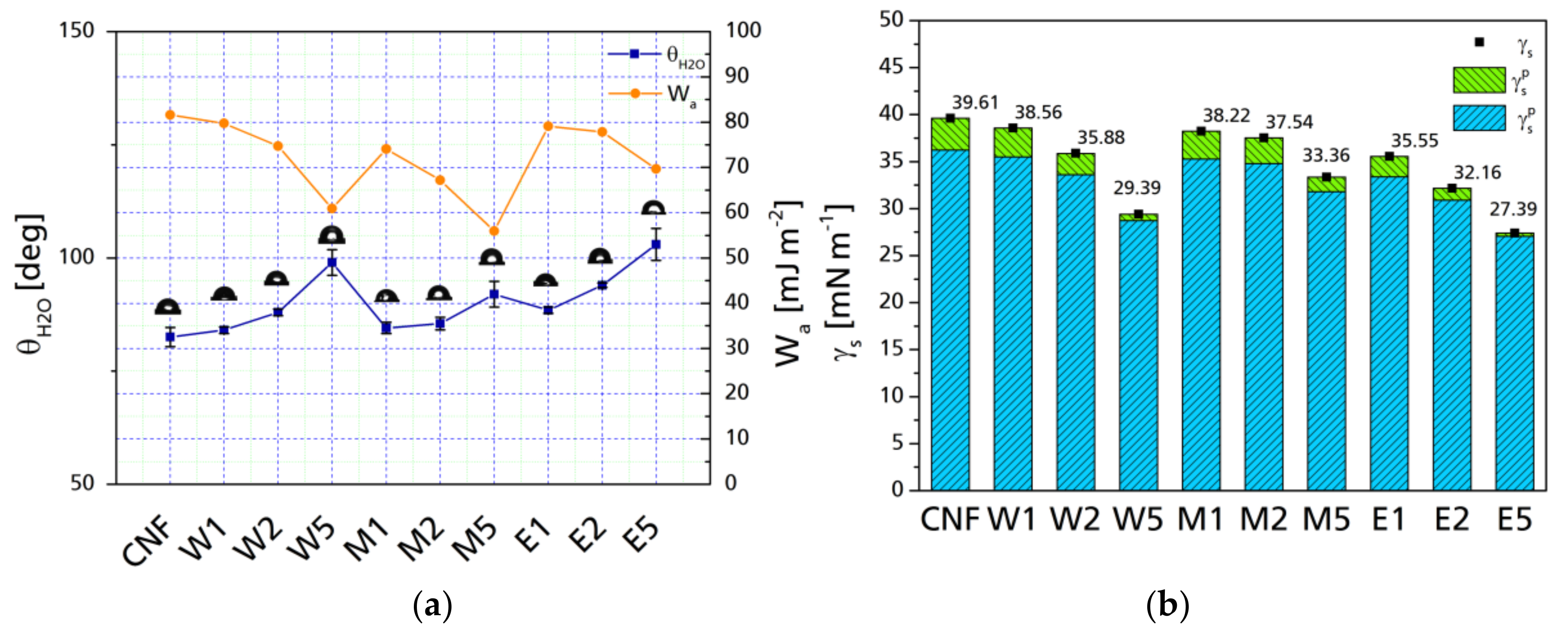
Surface modification with silanes increases the hydrophobicity of cellulose fibrils. Contact angle provides further information regarding the interaction between the surface of the CNF before and after surface modification. Figure 7a presents the water contact angles (θH₂O) of CNF before and after chemical modification. The changes in θH₂O are related to the topology of the surface, either because of the size of the particle avoids the surface roughness or, because of the reaction of hydroxyl groups through hydrogen bonds, a surface can be considered hydrophobic when θH₂O is between 90° and 120°, while surfaces presenting lower θH₂O are considered hydrophilic and above 150° are considered super-hydrophobic [47]. In case of modified cellulose nanoparticles, even though during surface modification, not all hydroxyl groups may react, the possibility of water molecules to penetrate the substrate when dealing at the nano-scale is reduced. In general, an increase in the water contact angle can be observed as the number of silanes is increased; this is related to the features associated with the components of the respective modification, as well as with the specific surface of the particle; nano-scale cellulose has more hydroxyl groups to react with, which acts as a shield against water sorption [48,49]. The contact angle is related proportionally to the silane content in the reaction, with no significant difference between the different aqueous media. In the case of M5, the contact angle is not as high as for W5 or E5 (polar component is also significantly higher than for W5 and E5). This phenomenon was not present in cases of M1 and M2 which are very similar to their counterparts elaborated with either water or ethanol. The right axis presents the work of adhesion of between water and the surface of the fibrils. A decrease in the work of adhesion implies a higher degree of wetting, therefore, the water contact angle is directly related with a decrease in the dispersive adhesion. This can be further appreciated with the decomposition of the surface free energy in its polar and dispersive components.
Figure 7b presents the surface free energies (γs) as well as their polar and dispersive contributions. While there is a general decrease in surface free energy, the most significant change is in the polar component, which is changed from an original 3.39 mN m−1 to 0.67 and 0.33 mN m−1 for W5 and E5 respectively. This is an 80% and 90% reduction of the surface polarity of the CNF when the maximum amount of silane was added, which is significantly higher than previous reports [50]. Changes can be seen with low silane yield (W1, M1, and E1) in which the surface polarity is reduced slightly in the case of water-based modifications (10% for W1 and 13% for M1) but with a 35% reduction for modifications performed in ethanol.
4. Conclusions
Nine different nanocellulose modifications were done to functionalize CNF obtained from native cellulose. The properties of each type were analyzed to evaluate their potential use for different applications. In general, the variation in properties is directly related to the amount of silane used in the reaction with particularities occurring between the different aqueous media. The overall analysis of the performed modifications shows that the best performing silane to cellulose ratio is 2:1, which is consistent with the literature, showing little differences with 5:1, thus implying a resource optimization. Regarding the solvent systems, ethanol-based modifications resulted in a cleavage of the propyl chains to the crystalline region of C4 and C6, which may imply a CNF cutting, which is visible in the AFM image and in XRD analysis. In case of water-based systems, the oligomerization of silanes on the surface is more evident, as can be seen in 29Si NMR, having larger contributions of 3D oligomers, and in the 13C NMR analysis at the βCH2 (CH2) region of the propyl chain and the CH2 CH3 positions which correspond to chain oligomerization. This is further confirmed in the XRD analysis with the apparition of a larger “hump” in the 2θ scatter between 20° and 30°.
Supplementary Materials
The following are available online at https://www.mdpi.com/2079-6412/8/4/139/s1, Figure S1: 13C NMR resonances of ATS, Figure S2: Full 13C NMR resonances of all the samples, Figure S3: Full infrared spectra of all the samples, Figure S4: FT-IR spectrum of ATS (normalized).
Acknowledgments
The authors would like to acknowledge the Basque Government (IT1008-16) and Mexican Council of Science and Technology (CONACyT), through scholarship No. 216178 for financially supporting this work. This article was also made in frame of the “EFOP-3.6.1-16-2016-00018—Improving the role of research + development + innovation in the higher education through institutional developments assisting intelligent specialization in Sopron and Szombathely”.
Author Contributions
E.R. and J.L. conceived and designed the experiments; E.R. performed the experiments; E.R. and L.C. analyzed the data; J.L. contributed reagents/materials/analysis tools; E.R. wrote the paper.
Conflicts of Interest
The authors declare no conflict of interest. The founding sponsors had no role in the design of the study; in the collection, analyses, or interpretation of data; in the writing of the manuscript, and in the decision to publish the results.
References
- Turbak, A.F.; Snyder, F.W.; Sandberg, K.R. Microfibrillated cellulose, a new cellulose product: Properties, uses, and commercial potential. In Proceedings of the Conference: 9. cellulose conference, Syracuse, NY, USA, 24 May 1982; ITT Rayonier Inc.: Shelton, WA, USA, 1983. [Google Scholar]
- Siqueira, G.; Bras, J.; Dufresne, A. New process of chemical grafting of cellulose nanoparticles with a long chain isocyanate. Langmuir 2010, 26, 402–411. [Google Scholar] [CrossRef] [PubMed]
- Lagerwall, J.P.F.; Schütz, C.; Salajkova, M.; Noh, J.; Hyun Park, J.; Scalia, G.; Bergström, L. Cellulose nanocrystal-based materials: From liquid crystal self-assembly and glass formation to multifunctional thin films. NPG Asia Mater. 2014, 6, e80. [Google Scholar] [CrossRef]
- Kalia, S.; Kaith, B.S.; Kaur, I. Pretreatments of natural fibers and their application as reinforcing material in polymer composites-A review. Polym. Eng. Sci. 2009, 49, 1253–1272. [Google Scholar] [CrossRef]
- Heux, L.; Chauve, G.; Bonini, C. Nonflocculating and chiral-nematic self-ordering of cellulose microcrystals suspensions in nonpolar solvents. Langmuir 2000, 16, 8210–8212. [Google Scholar] [CrossRef]
- Hubbe, M.A.; Rojas, O.J.; Lucia, L.A.; Sain, M. Cellulosic nanocomposites: A review. BioResources 2008, 3, 929–980. [Google Scholar] [CrossRef]
- Akil, H.M.; Omar, M.F.; Mazuki, A.A.M.; Safiee, S.; Ishak, Z.A.M.; Abu Bakar, A. Kenaf fiber reinforced composites: A review. Mater. Des. 2011, 32, 4107–4121. [Google Scholar] [CrossRef]
- Abdul Khalil, H.P.S.; Davoudpour, Y.; Islam, M.N.; Mustapha, A.; Sudesh, K.; Dungani, R.; Jawaid, M. Production and modification of nanofibrillated cellulose using various mechanical processes: A review. Carbohydr. Polym. 2014, 99, 649–665. [Google Scholar] [CrossRef] [PubMed]
- Goussé, C.; Chanzy, H.; Cerrada, M.L.; Fleury, E. Surface silylation of cellulose microfibrils: Preparation and rheological properties. Polymer 2004, 45, 1569–1575. [Google Scholar] [CrossRef]
- Lu, J.; Askeland, P.; Drzal, L.T. Surface modification of microfibrillated cellulose for epoxy composite applications. Polymer 2008, 49, 1285–1296. [Google Scholar] [CrossRef]
- Laitinen, O.; Suopajärvi, T.; Österberg, M.; Liimatainen, H. Hydrophobic, superabsorbing aerogels from choline chloride-based deep eutectic solvent pretreated and silylated cellulose nanofibrils for selective oil removal. ACS Appl. Mater. Interfaces 2017, 9, 25029–25037. [Google Scholar] [CrossRef] [PubMed]
- Xu, S.H.; Gu, J.; Luo, Y.F.; Jia, D.M. Effects of partial replacement of silica with surface modified nanocrystalline cellulose on properties of natural rubber nanocomposites. Express Polym. Lett. 2012, 6, 14–25. [Google Scholar] [CrossRef] [Green Version]
- Raquez, J.M.; Murena, Y.; Goffin, A.L.; Habibi, Y.; Ruelle, B.; DeBuyl, F.; Dubois, P. Surface-modification of cellulose nanowhiskers and their use as nanoreinforcers into polylactide: A sustainably-integrated approach. Compos. Sci. Technol. 2012, 72, 544–549. [Google Scholar] [CrossRef]
- Xie, Y.; Hill, C.A.S.; Xiao, Z.; Militz, H.; Mai, C. Silane coupling agents used for natural fiber/polymer composites: A review. Compos. Part A Appl. Sci. Manuf. 2010, 41, 806–819. [Google Scholar] [CrossRef]
- Maldas, D.; Kokta, B.V.; Daneault, C. Influence of coupling agents and treatments on the mechanical properties of cellulose fiber-polystyrene composites. J. Appl. Polym. Sci. 1989, 37, 751–775. [Google Scholar] [CrossRef]
- Witucki, G.L. A silane primer: Chemistry and applications of aikoxy silanes. J. Coat. Technol. 1993, 65, 57–67. [Google Scholar]
- Kahn, F.J. Orientation of liquid crystals by surface coupling agents. Appl. Phys. Lett. 1973, 22, 386–388. [Google Scholar] [CrossRef]
- Arkles, B. Silane Coupling Agents: Connecting Acros Boundaries; Gelest Inc.: Morrisville, PA, USA, 2006; pp. 1–21. [Google Scholar]
- Andresen, M.; Johansson, L.-S.; Tanem, B.S.; Stenius, P. Properties and characterization of hydrophobized microfibrillated cellulose. Cellulose 2006, 13, 665–677. [Google Scholar] [CrossRef]
- Robles, E.; Urruzola, I.; Labidi, J.; Serrano, L. Surface-modified nano-cellulose as reinforcement in poly(lactic acid) to conform new composites. Ind. Crops Prod. 2015, 71, 44–53. [Google Scholar] [CrossRef]
- Robles, E.; Czubak, E.; Kowaluk, G.; Labidi, J. Lignocellulosic-based multilayer self-bonded composites with modified cellulose nanoparticles. Compos. Part B Eng. 2016, 106, 300–307. [Google Scholar] [CrossRef]
- Robles, E.; Fernández-Rodríguez, J.; Barbosa, A.M.; Gordobil, O.; Carreño, N.L.V.; Labidi, J. Production of cellulose nanoparticles from blue agave waste treated with environmentally friendly processes. Carbohydr. Polym. 2018, 183, 294–302. [Google Scholar] [CrossRef] [PubMed]
- Oostendorp, D.J.; Bertrand, G.L.; Stoffer, J.O. Kinetics and mechanism of the hydrolysis and alcoholysis of alkoxysilanes. J. Adhes. Sci. Technol. 1992, 6, 171–191. [Google Scholar] [CrossRef]
- Abdelmouleh, M.; Boufi, S.; ben Salah, A.; Belgacem, M.N.; Gandini, A. Interaction of silane coupling agents with cellulose. Langmuir 2002, 18, 3203–3208. [Google Scholar] [CrossRef]
- Bordeanu, N.; Eyhozler, C.; Zimmermann, T. Surface Modified Cellulose Nanofibrils. WO Application No. WO2010066905A1, 17 June 2010. [Google Scholar]
- ASTM E1131-08 Standard Test Method for Compositional Analysis by Thermogravimetry; ASTM: West Conshohocken, PA, USA, 2014.
- Owens, D.K.; Wendt, R.C. Estimation of the surface free energy of polymers. J. Appl. Polym. Sci. 1969, 13, 1741–1747. [Google Scholar] [CrossRef]
- Rabel, W. Einige Aspekte der Benetzungstheorie und ihre Anwendung auf die Untersuchung und Veränderung der Oberflächeneigenschaften von Polymeren. Farbe und Lack 1971, 77, 997–1005. (In German) [Google Scholar]
- Kaelble, D.H. Dispersion-polar surface tension properties of organic solids. J. Adhes. 1970, 2, 66–81. [Google Scholar] [CrossRef]
- Daniels, M.W.; Francis, L.F. Silane adsorption behavior, microstructure, and properties of glycidoxypropyltrimethoxysilane-modified colloidal silica coatings. J. Colloid Interface Sci. 1998, 205, 191–200. [Google Scholar] [CrossRef] [PubMed]
- Paunikallio, T.; Suvanto, M.; Pakkanen, T.T. Viscose fiber/polyamide 12 composites: Novel gas-phase method for the modification of cellulose fibers with an aminosilane coupling agent. J. Appl. Polym. Sci. 2006, 102, 4478–4483. [Google Scholar] [CrossRef]
- Salon, M.-C.B.; Abdelmouleh, M.; Boufi, S.; Belgacem, M.N.; Gandini, A. Silane adsorption onto cellulose fibers: Hydrolysis and condensation reactions. J. Colloid Interface Sci. 2005, 289, 249–261. [Google Scholar] [CrossRef] [PubMed]
- Fernandes, S.C.M.; Sadocco, P.; Alonso-Varona, A.; Palomares, T.; Eceiza, A.; Silvestre, A.J.D.; Mondragon, I.; Freire, C.S.R. Bioinspired antimicrobial and biocompatible bacterial cellulose membranes obtained by surface functionalization with aminoalkyl groups. ACS Appl. Mater. Interfaces 2013, 5, 3290–3297. [Google Scholar] [CrossRef] [PubMed]
- Khanjanzadeh, H.; Behrooz, R.; Bahramifar, N.; Gindl-Altmutter, W.; Bacher, M.; Edler, M.; Griesser, T. Surface chemical functionalization of cellulose nanocrystals by 3-aminopropyltriethoxysilane. Int. J. Biol. Macromol. 2017, 106, 1288–1296. [Google Scholar] [CrossRef] [PubMed]
- Salon, M.-C.B.; Gerbaud, G.; Abdelmouleh, M.; Bruzzese, C.; Boufi, S.; Belgacem, M.N. Studies of interactions between silane coupling agents and cellulose fibers with liquid and solid-state NMR. Magn. Reson. Chem. 2007, 45, 473–483. [Google Scholar] [CrossRef] [PubMed]
- Roche, V.; Perrin, F.X.; Gigmes, D.; Vacandio, F.; Ziarelli, F.; Bertin, D. Tracking the fate of γ-aminopropyltriethoxysilane from the sol state to the dried film state. Thin Solid Films 2010, 518, 3640–3645. [Google Scholar] [CrossRef]
- Glasser, R.H.; Wilkes, G.L.; Bronnimann, C.E. Solid-state 29Si NMR of TEOS-based multifunctional SOL-GEL materials. J. Non-Cryst. Solids 1989, 113, 73–87. [Google Scholar] [CrossRef]
- Zeng, Y.; Taniike, T.; Terano, M. Design of homogeneous Phillips type catalyst by silsequoxane support. In 44th Petroleum-Petrochemical Symposium of JPI, Proceedings of Annual/Fall Meetings of the Japan Petroleum Institute, Asahikawa, Japan, 16–18 October 2014; J-STAGE: Tokyo, Japan, 2014; p. 3. [Google Scholar]
- Pacaphol, K.; Aht-Ong, D. The influences of silanes on interfacial adhesion and surface properties of nanocellulose film coating on glass and aluminum substrates. Surf. Coat. Technol. 2017, 320, 70–81. [Google Scholar] [CrossRef]
- Liu, H.; Zhang, L. Silylation of cellulose with trichlorosilane and triethoxysilane in homogeneous LiCl/N,N-dimethylacetamide solution. Chin. J. Polym. Sci. 2000, 18, 161–168. [Google Scholar]
- Fathi, B.; Harirforoush, M.J.; Foruzanmehr, M.R.; Elkoun, S.; Robert, M. Effect of TEMPO oxidation of flax fibers on the grafting efficiency of silane coupling agents. J. Mater. Sci. 2017, 52, 10624–10636. [Google Scholar] [CrossRef]
- Rachini, A.; Le Troedec, M.; Peyratout, C.; Smith, A. Comparison of the thermal degradation of natural, alkali-treated and silane-treated hemp fibers under air and an inert atmosphere. J. Appl. Polym. Sci. 2009, 112, 226–234. [Google Scholar] [CrossRef]
- Ioelovich, M.; Leykin, A.; Figovsky, O. Study of cellulose paracrystallinity. BioResources 2010, 5, 1393–1407. [Google Scholar]
- Thanomchat, S.; Schlarb, A.K. Morphology and crystallization of polypropylene/microfibrillated cellulose composites. Int. J. Appl. Sci. Technol. 2014, 7, 23–34. [Google Scholar] [CrossRef]
- Shabir, Q.; Pokale, A.; Loni, A.; Johnson, D.R.; Canham, L.T.; Fenollosa, R.; Tymczenko, M.; Rodríguez, I.; Meseguer, F.; Cros, A.; et al. Medically biodegradable hydrogenated amorphous silicon microspheres. Silicon 2011, 3, 173–176. [Google Scholar] [CrossRef]
- Linck, C.; Ionescu, E.; Papendorf, B.; Galuskova, D.; Galusekb, D.; Sajgalíkc, P.; Riedel, R. Corrosion behavior of silicon oxycarbide-based ceramic nanocomposites under hydrothermal conditions. Int. J. Mater. Res. 2012, 103, 31–39. [Google Scholar] [CrossRef]
- Feng, L.; Li, S.; Li, Y.; Li, H.; Zhang, L.; Zhai, J.; Song, Y.; Liu, B.; Jiang, L.; Zhu, D. Super-hydrophobic surfaces: From natural to artificial. Adv. Mater. 2002, 14, 1857–1860. [Google Scholar] [CrossRef]
- Fadeev, A.Y.; McCarthy, T.J. Trialkylsilane monolayers covalently attached to silicon surfaces: Wettability studies indicating that molecular topography contributes to contact angle hysteresis. Langmuir 1999, 15, 3759–3766. [Google Scholar] [CrossRef]
- Dankovich, T.A.; Gray, D.G. Contact angle measurements on smooth nanocrystalline cellulose (I) thin films. J. Adhes. Sci. Technol. 2011, 25, 699–708. [Google Scholar] [CrossRef]
- Abdelmouleh, M.; Boufi, S.; Belgacem, M.N.; Duarte, A.P.; Ben Salah, A.; Gandini, A. Modification of cellulosic fibres with functionalised silanes: Development of surface properties. Int. J. Adhes. Adhes. 2004, 24, 43–54. [Google Scholar] [CrossRef]
Scheme 1.
Reaction dynamics for the cellulose–silane interactions.

Figure 1.
NMR spectra of cellulose nanofibers before and after modification: (a) 13C resonances in the C4 region; (b) 13C resonances in the C6 region; (c) 13C resonances in the range of 3-aminopropyl triethoxysilane (ATS); (d) percentile contributions of 13C chemical shifts of modified CNF; and (e) carbon identification in the ATS and cellulose glucose unit.
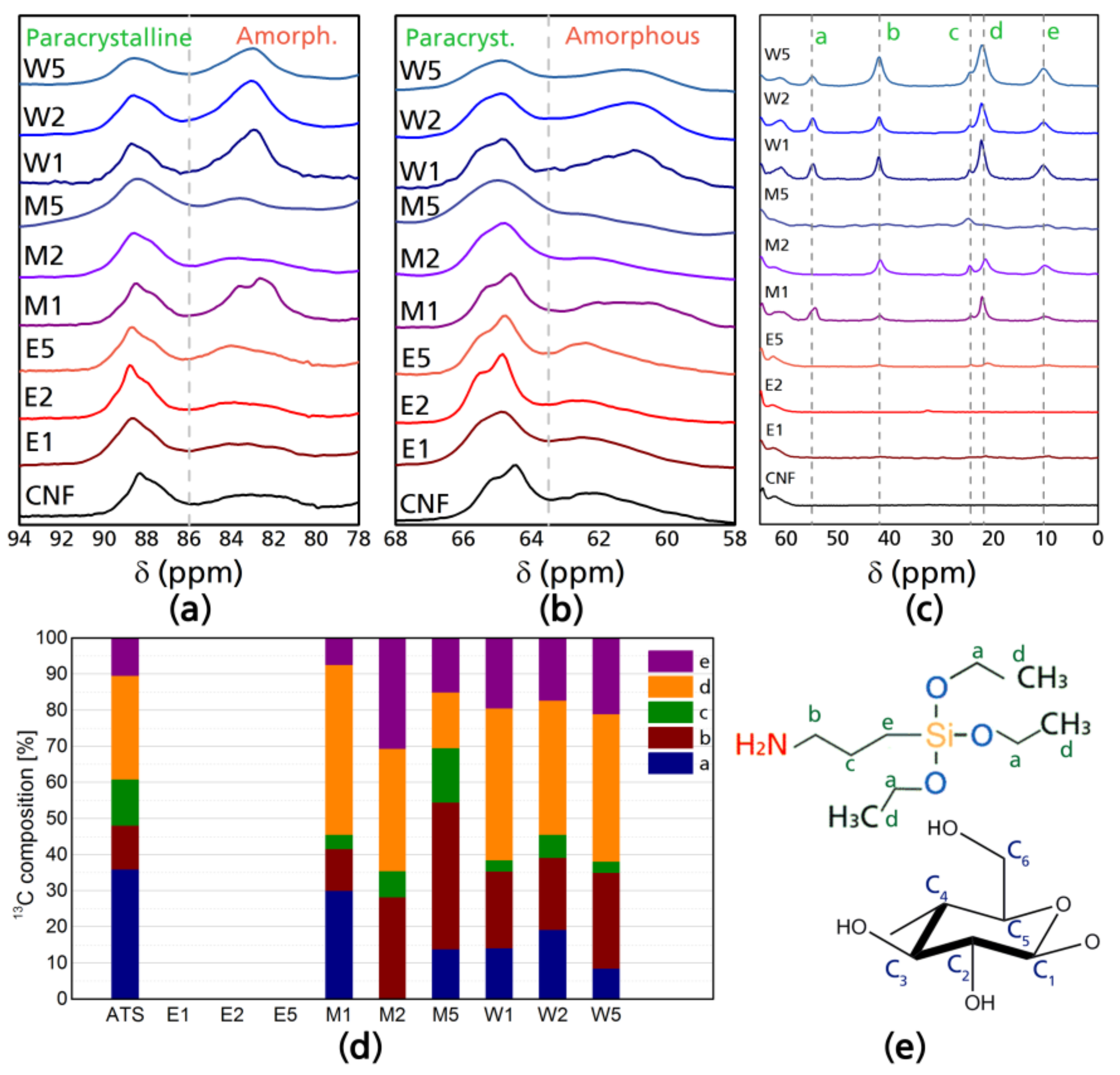
Figure 2.
29Si NMR chemical shifts of cellulose nanofibers after modification (a) and structure composition of the different silane tetrahedral structures (b).
Figure 2.
29Si NMR chemical shifts of cellulose nanofibers after modification (a) and structure composition of the different silane tetrahedral structures (b).
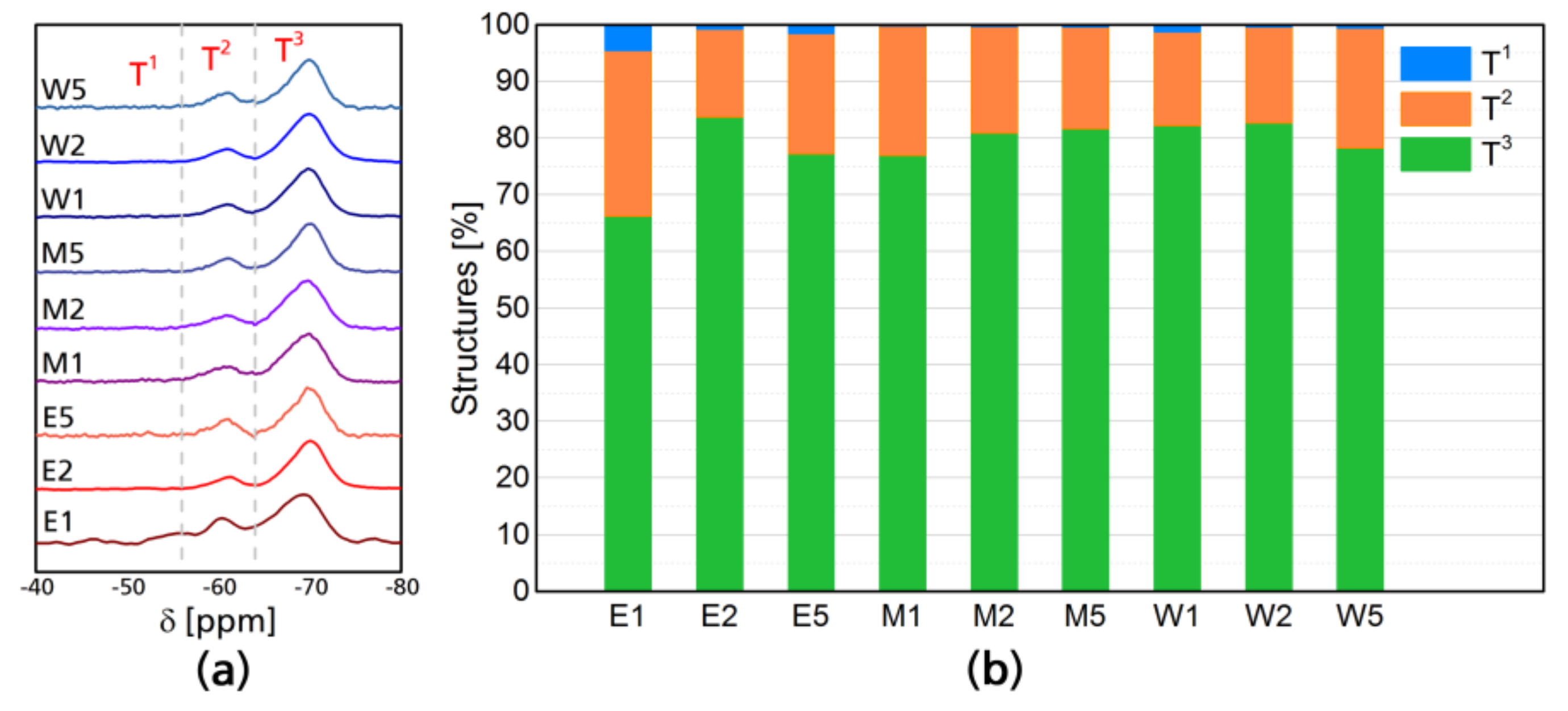
Figure 3.
Atomic force microscopy (AFM) images of W5 (a), M5 (b); and E5 (c) corresponding to a single fiber; and W5 (d), M5 (e) and E5 (f) corresponding to the 2D surface.
Figure 3.
Atomic force microscopy (AFM) images of W5 (a), M5 (b); and E5 (c) corresponding to a single fiber; and W5 (d), M5 (e) and E5 (f) corresponding to the 2D surface.

Figure 4.
FT-IR spectra of modified and neat CNF: (a) 1800–800 cm−1 region; (b) 1600–1450 cm−1 region, in which the amino bending is appreciable; and (c) 900–400 cm−1 region.
Figure 4.
FT-IR spectra of modified and neat CNF: (a) 1800–800 cm−1 region; (b) 1600–1450 cm−1 region, in which the amino bending is appreciable; and (c) 900–400 cm−1 region.
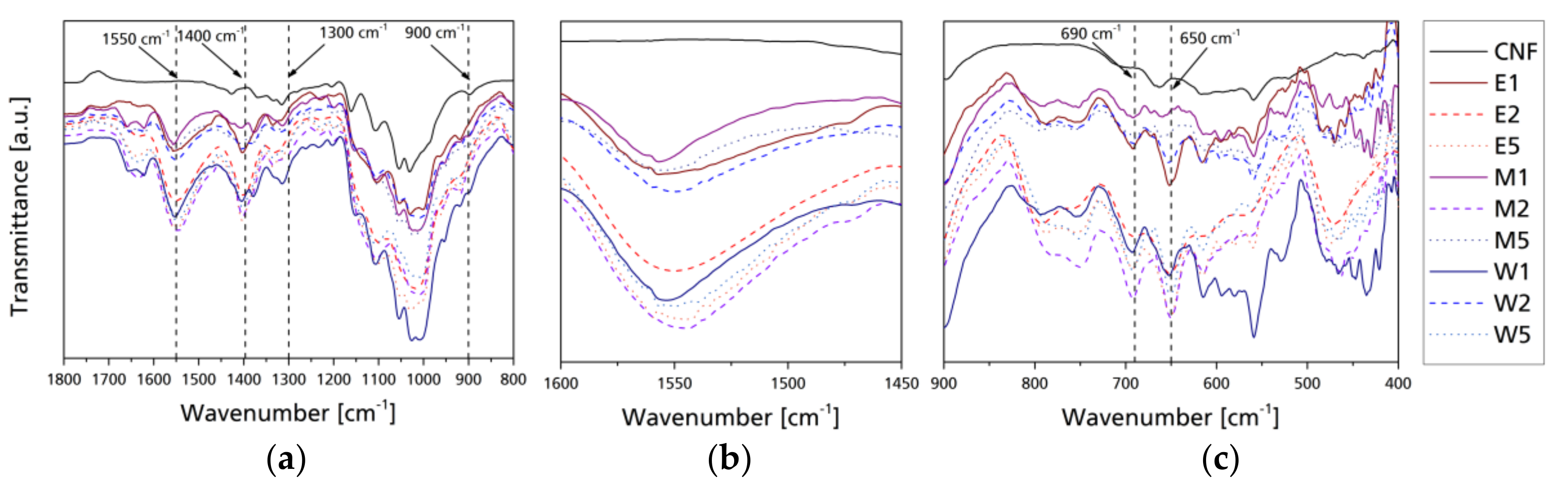
Figure 5.
Thermogravimetric curves of native and modified CNF (a); derivative thermogravimetric curves (b), and grafted silane per gram of cellulose (c).
Figure 5.
Thermogravimetric curves of native and modified CNF (a); derivative thermogravimetric curves (b), and grafted silane per gram of cellulose (c).
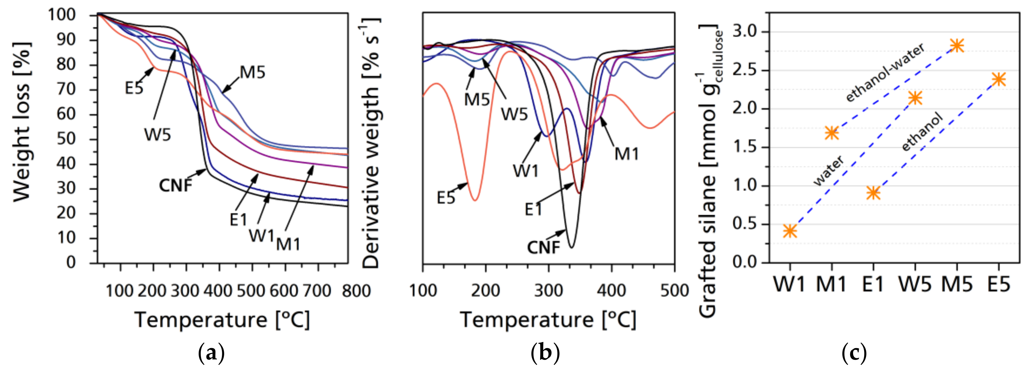
Figure 6.
Raw XRD scatters with fitted curves for crystalline signals. Inserts: normalized individual signals corresponding to cellulose and modified cellulose diffraction planes.
Figure 6.
Raw XRD scatters with fitted curves for crystalline signals. Inserts: normalized individual signals corresponding to cellulose and modified cellulose diffraction planes.

Figure 7.
Water contact angle and S/L work of adhesion for neat and modified CNF after 60 s (a) and Surface free energy with polar (γsp) and dispersive (γsd) components (b).
Figure 7.
Water contact angle and S/L work of adhesion for neat and modified CNF after 60 s (a) and Surface free energy with polar (γsp) and dispersive (γsd) components (b).


Table 1.
Samples and treatment conditions of the cellulose nanofibrils (CNF), TR is the reaction temperature and TC is the curing temperature.
Table 1.
Samples and treatment conditions of the cellulose nanofibrils (CNF), TR is the reaction temperature and TC is the curing temperature.
| Sample | Solvent | ATS Equivalent Ratio | TR (°C) | TC (°C) | t (min) | |
|---|---|---|---|---|---|---|
| Water | Ethanol | |||||
| CNF | – | – | 0 | 0 | 0 | 0 |
| W1 | 100 | 0 | 1:1 | 20 | 105 | 50 |
| W2 | 100 | 0 | 1:2.5 | 20 | 105 | 50 |
| W5 | 100 | 0 | 1:5 | 20 | 105 | 50 |
| M1 | 50 | 50 | 1:1 | 20 | 105 | 50 |
| M2 | 50 | 50 | 1:2.5 | 20 | 105 | 50 |
| M5 | 50 | 50 | 1:5 | 20 | 105 | 50 |
| E1 | 0 | 100 | 1:1 | 20 | 105 | 50 |
| E2 | 0 | 100 | 1:2.5 | 20 | 105 | 50 |
| E5 | 0 | 100 | 1:5 | 20 | 105 | 50 |
© 2018 by the authors. Licensee MDPI, Basel, Switzerland. This article is an open access article distributed under the terms and conditions of the Creative Commons Attribution (CC BY) license (http://creativecommons.org/licenses/by/4.0/).
Share and Cite
MDPI and ACS Style
Robles, E.; Csóka, L.; Labidi, J. Effect of Reaction Conditions on the Surface Modification of Cellulose Nanofibrils with Aminopropyl Triethoxysilane. Coatings 2018, 8, 139. https://doi.org/10.3390/coatings8040139
AMA Style
Robles E, Csóka L, Labidi J. Effect of Reaction Conditions on the Surface Modification of Cellulose Nanofibrils with Aminopropyl Triethoxysilane. Coatings. 2018; 8(4):139. https://doi.org/10.3390/coatings8040139
Chicago/Turabian StyleRobles, Eduardo, Levente Csóka, and Jalel Labidi. 2018. "Effect of Reaction Conditions on the Surface Modification of Cellulose Nanofibrils with Aminopropyl Triethoxysilane" Coatings 8, no. 4: 139. https://doi.org/10.3390/coatings8040139
Note that from the first issue of 2016, this journal uses article numbers instead of page numbers. See further details here.