Electrodeposition of a Pd-Ni/TiO2 Composite Coating on 316L SS and Its Corrosion Behavior in Hot Sulfuric Acid Solution


Abstract
:1. Introduction
2. Materials and Methods
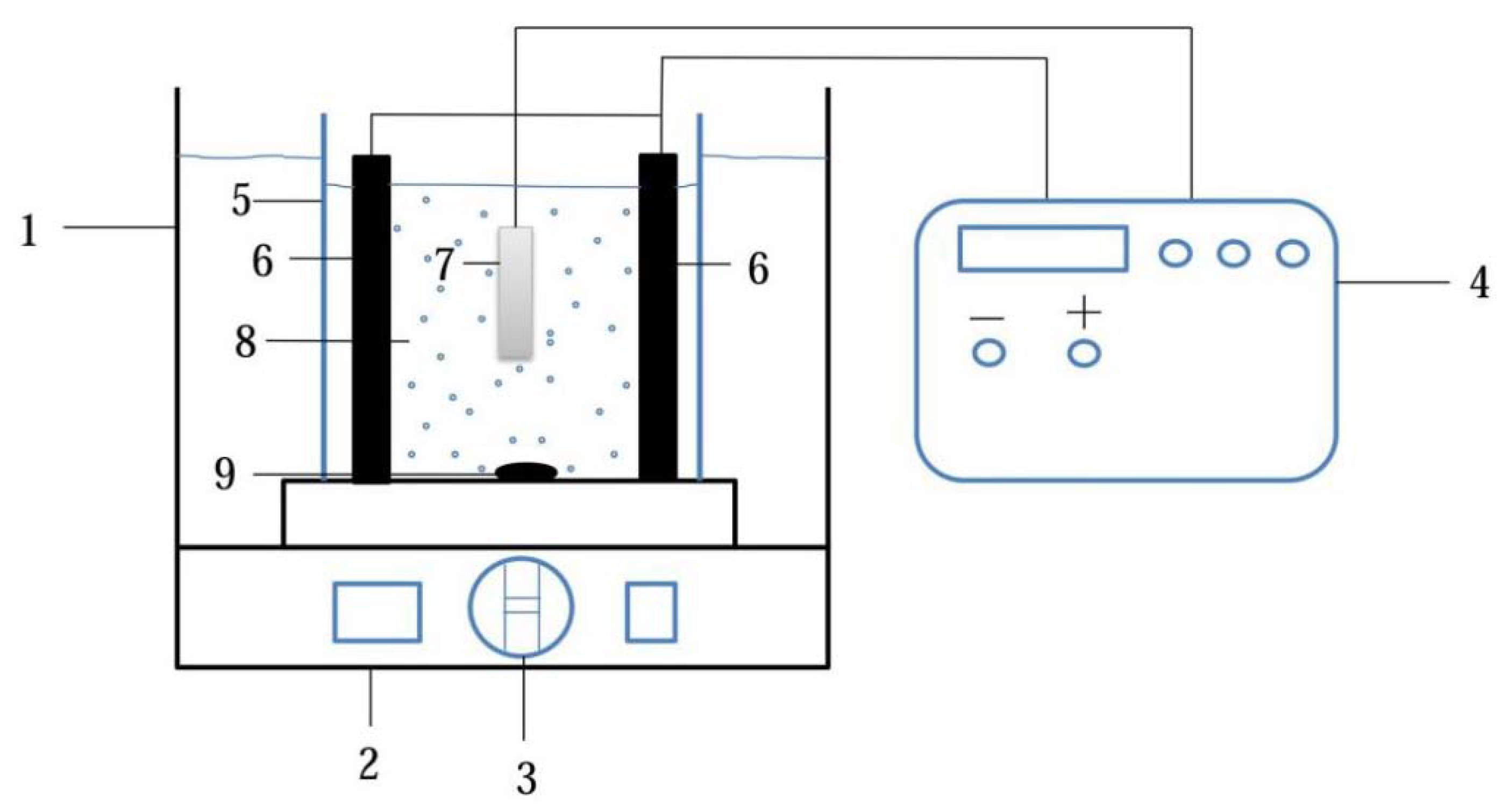
2.1. Elaboration of Pd-Ni/TiO2 Composite Coatings
2.2. Characterization of Pd–Ni/TiO2 Composite Coatings
2.3. Microhardness Measurements
2.4. Weight Loss Experiments
2.5. Electrochemical Corrosion Behavior
3. Results and Discussion
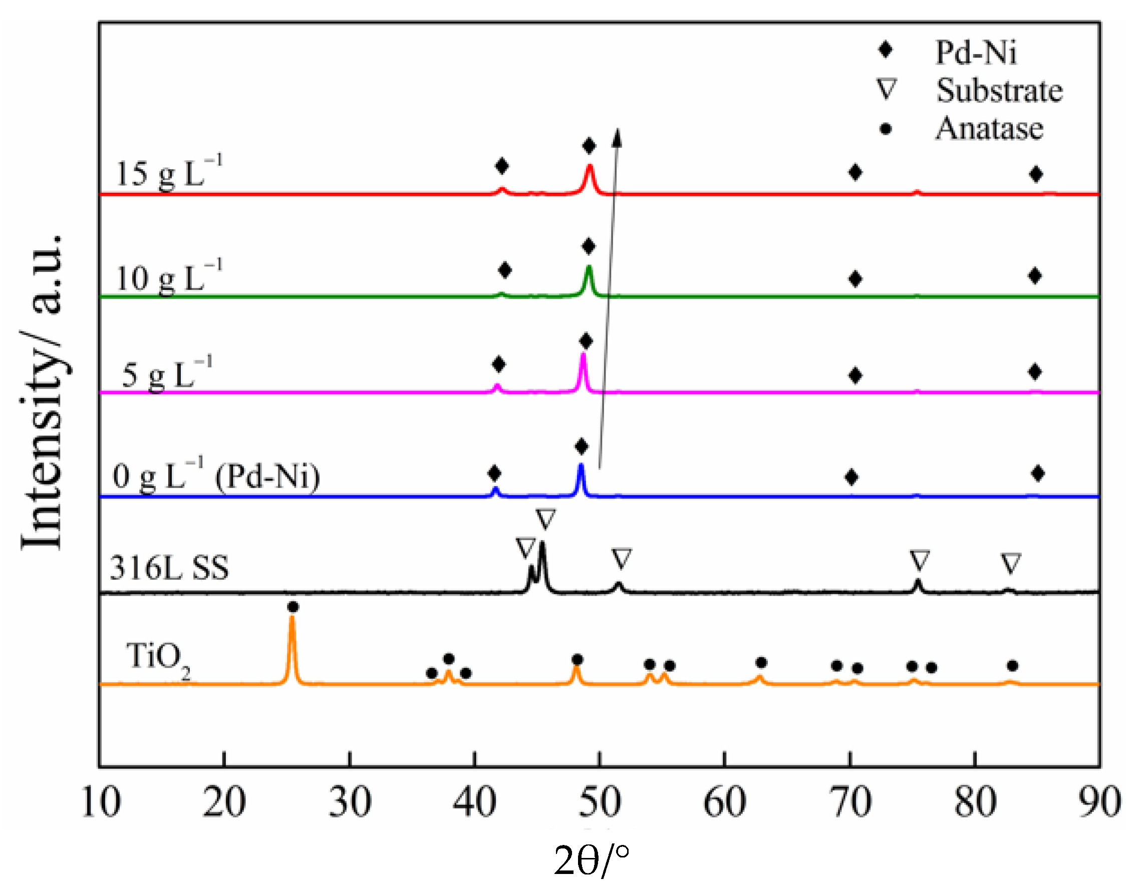
3.1. Characterization of the Composite Coatings
3.2. Microhardness Measurements
3.3. Weight Loss Tests
3.4. Electrochemical Tests
4. Conclusions
- (1)
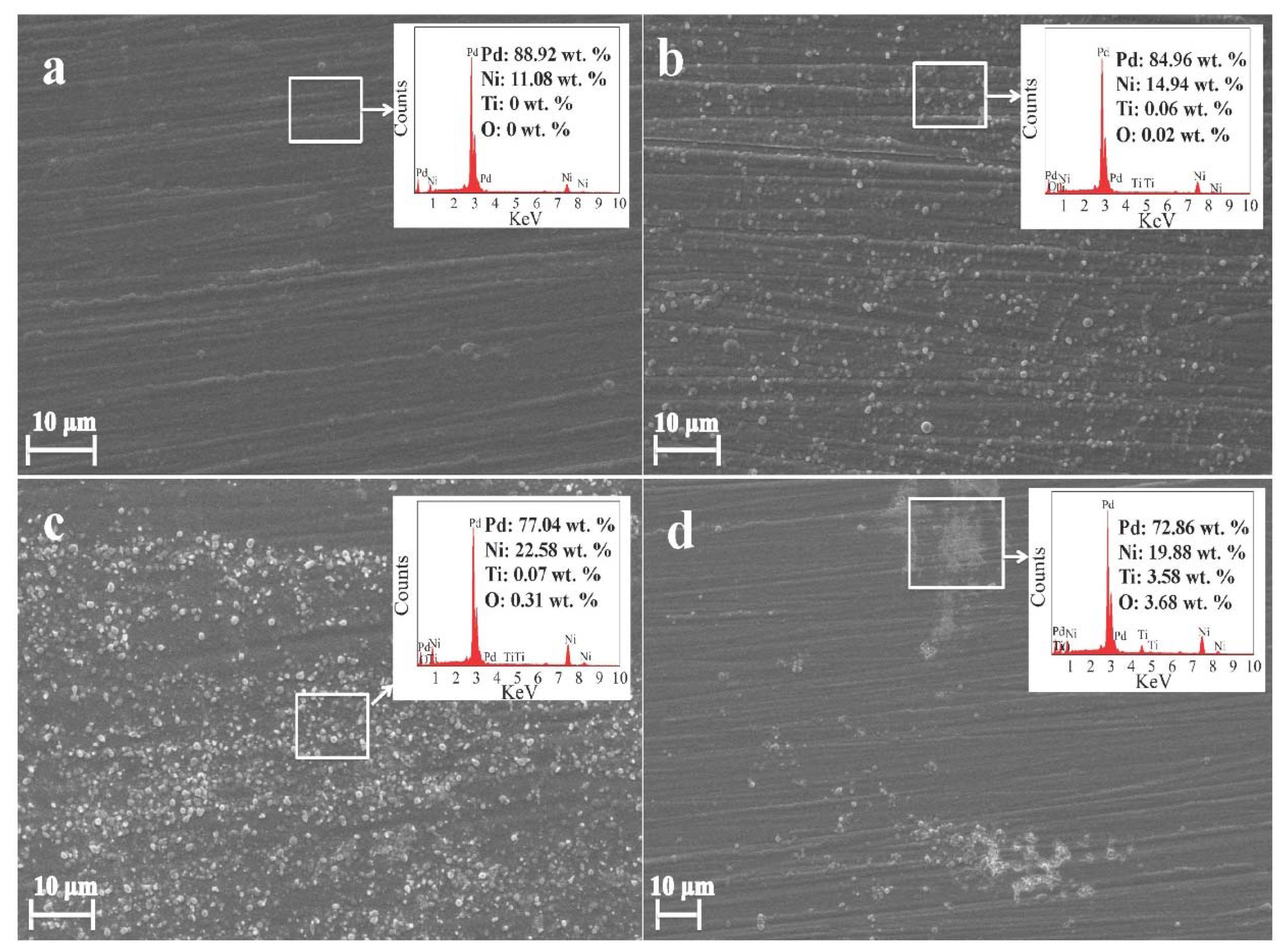
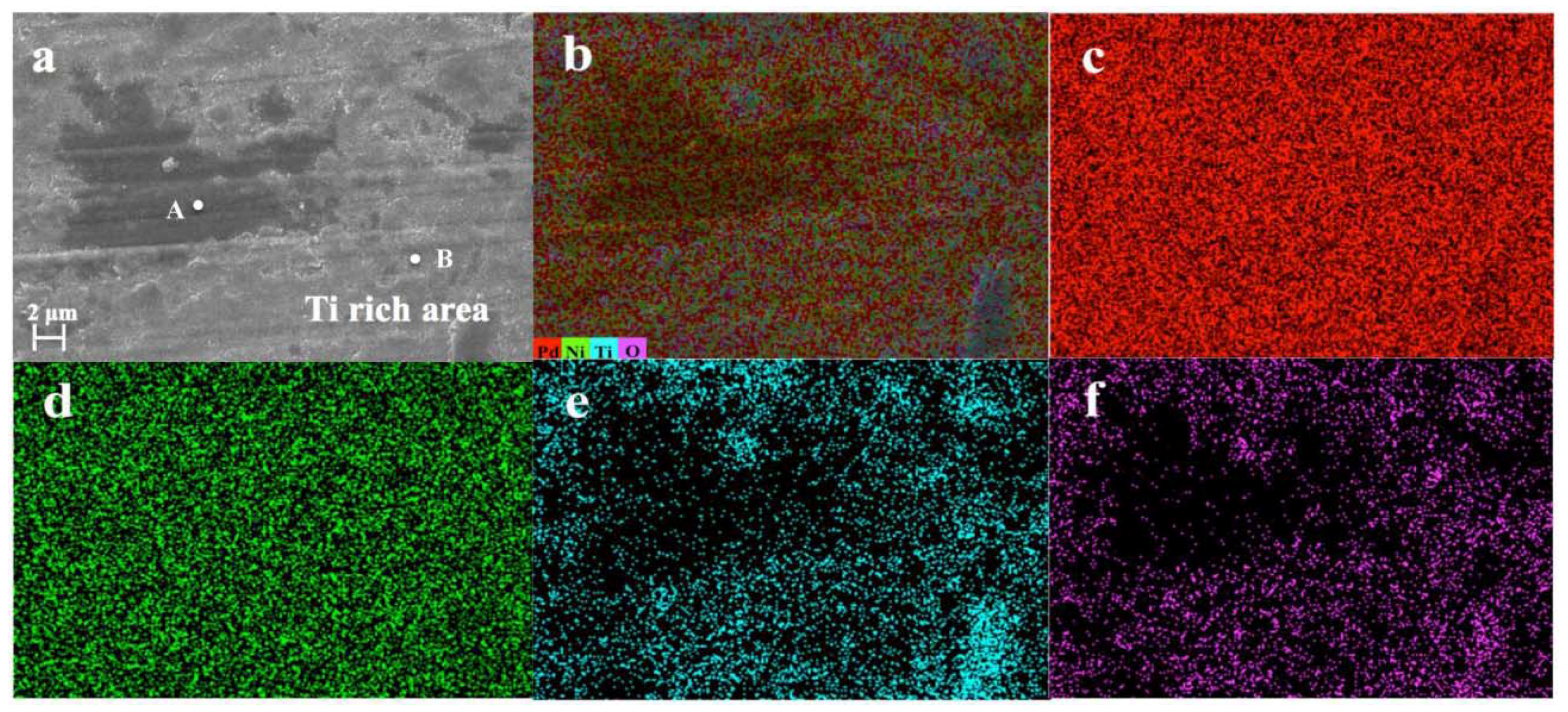
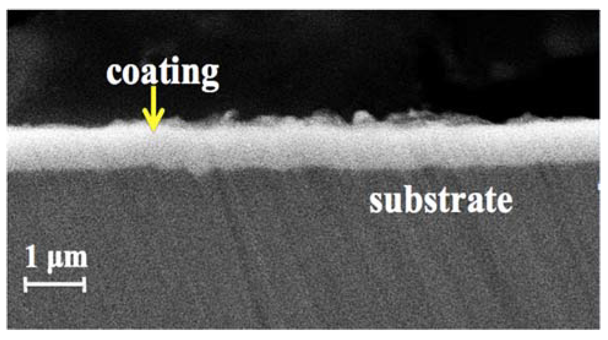
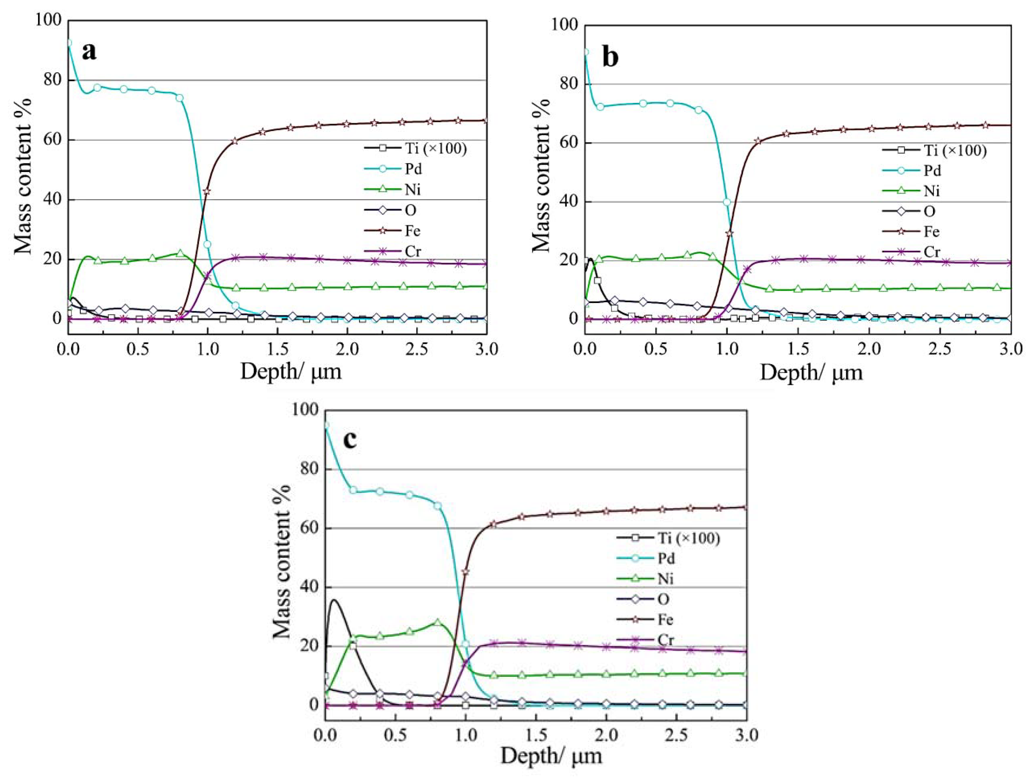
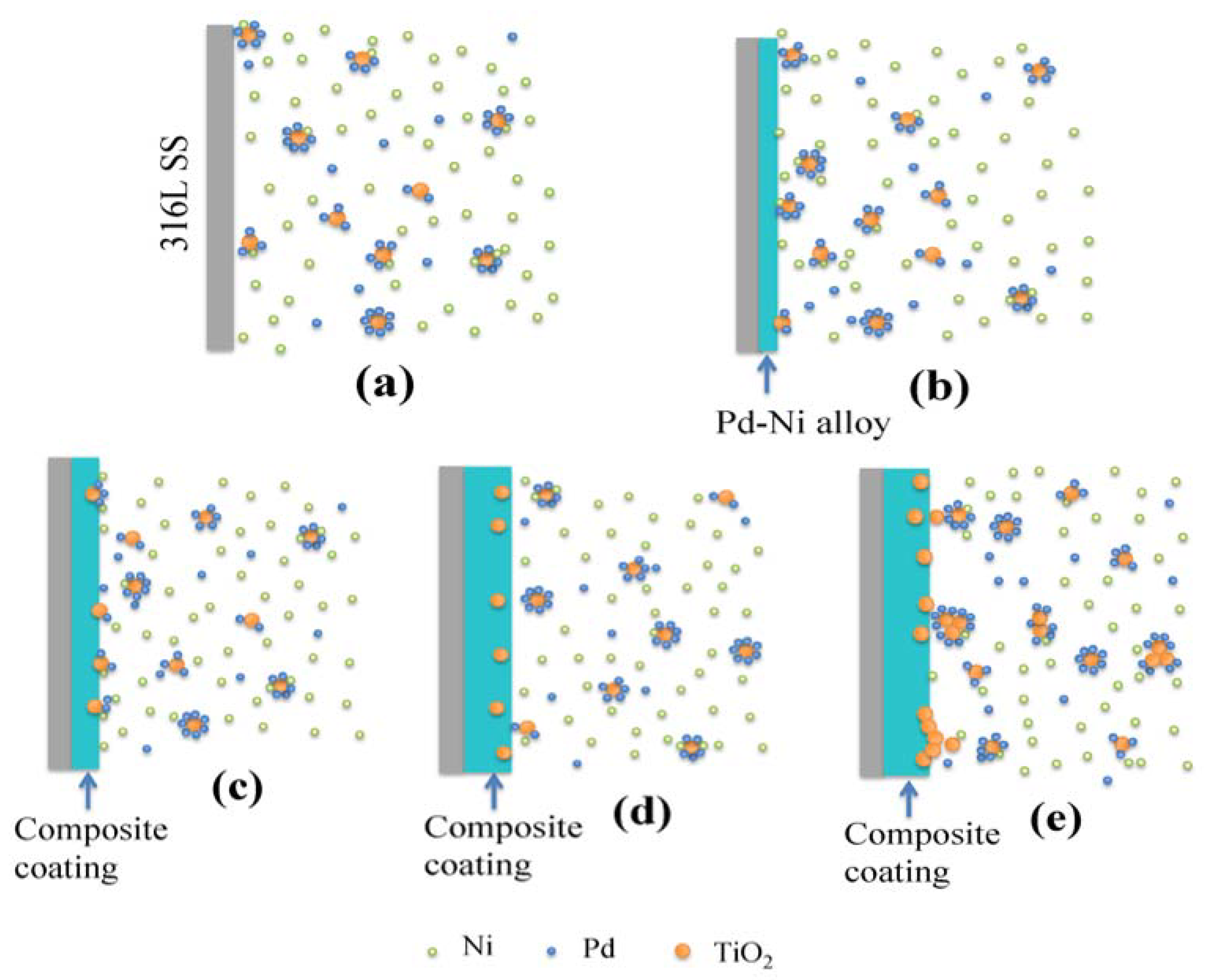
- With the addition of nanosized TiO2 particles in the electrolytic bath, the morphology of obtained Pd-Ni/TiO2 composite coatings was modified. In addition, up to 0.38 wt.% TiO2 particles were embedded in the alloy matrix from the deposition electrolyte containing 15 g/L TiO2 based on GDOES depth profiles. Furthermore, the addition of TiO2 particles can benefit the reduction of Ni in the coating. Most of the interior of the composite coating was composed of the Pd-Ni alloy. The deposition model of the Pd-Ni/TiO2 composite coatings were proposed based on different characterizations. After the initial electrodeposition of Pd-Ni alloy deposits, TiO2 started to strong adsorb on and embed into the growing coating matrix. Hence, TiO2 particles existed only in the exterior layer of the composite coatings, which also had a higher Pd content probably because more Pd ions and its complex were adsorbed on TiO2 particles in the electrolyte.
- (2)
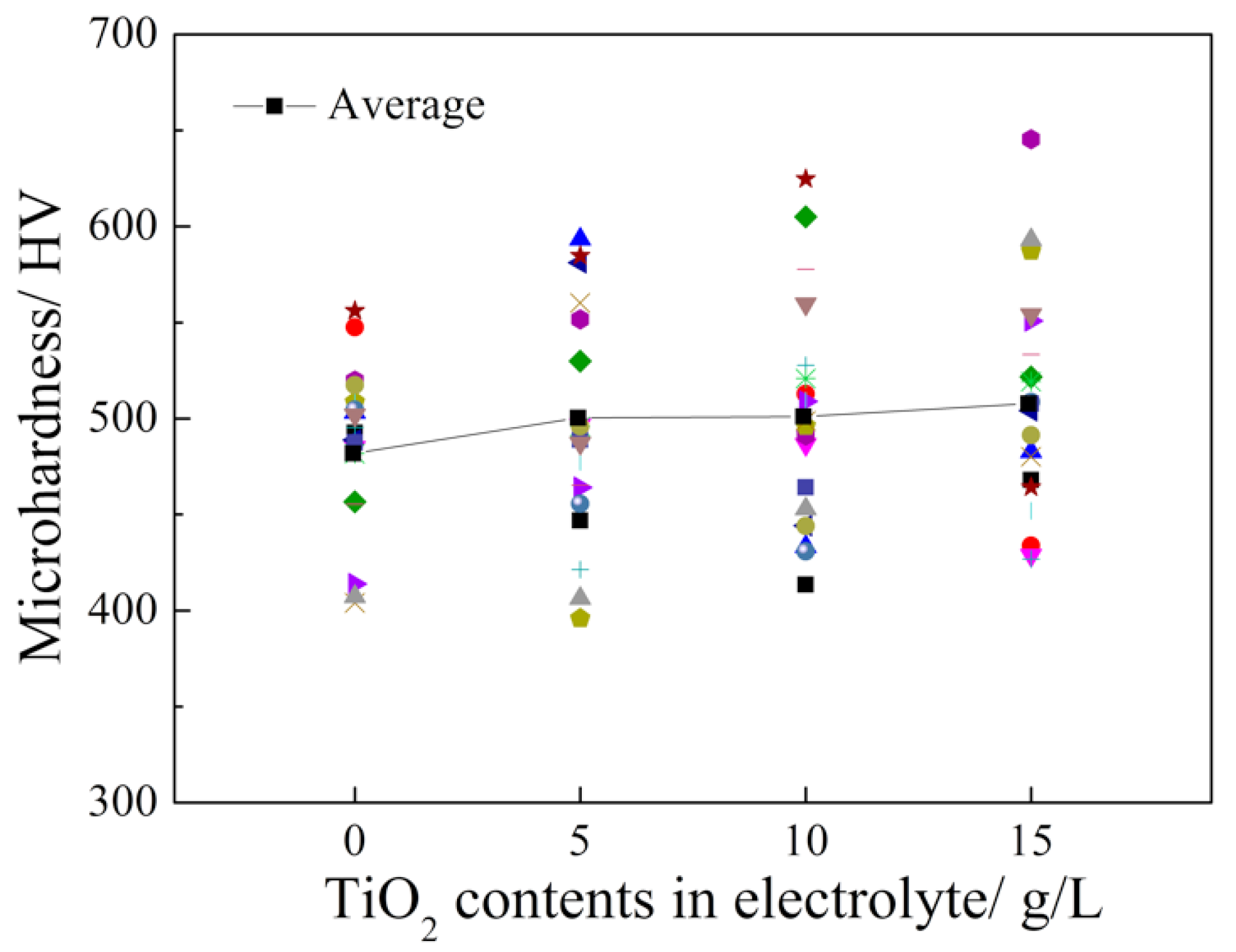
- The microhardness of the Pd-Ni/TiO2 composite coatings was improved by increasing the TiO2 content in the coatings. According to the weight loss and electrochemical test results, the specimen that was prepared from the electrolyte containing 5 g L−1 TiO2 showed the best corrosion resistance in 20 wt.% H2SO4 solution at 60 °C. Additionally, the composite coating exhibited a better corrosion resistance compared with that of the Pd-Ni alloy film that was obtained under the same conditions. In contrast, the further introduction of TiO2 particles into the electrolyte decreased the corrosion resistance of the obtained composite coatings because of agglomeration.
Author Contributions
Funding
Acknowledgments
Conflicts of Interest
References
- Tang, J.; Zuo, Y. Study on corrosion resistance of palladium films on 316L stainless steel by electroplating and electroless plating. Corros. Sci. 2008, 50, 2873–2878. [Google Scholar] [CrossRef]
- Lavigne, O.; Alemany-Dumont, C.; Normand, B.; Berthon-Fabry, S.; Metkemeijer, R. Thin chromium nitride PVD coatings on stainless steel for conductive component as bipolar plates of PEM fuel cells: Ex-situ and in-situ performances evaluation. Int. J. Hydrog. Energy 2012, 37, 10789–10797. [Google Scholar] [CrossRef]
- Dhandapani, V.S.; Subbiah, R.; Thangavel, E.; Arumugam, M.; Park, K.; Gasem, Z.M.; Veeraragavan, V.; Kim, D.E. Tribological properties, corrosion resistance and biocompatibility of magnetron sputtered titanium-amorphous carbon coatings. Appl. Surf. Sci. 2016, 371, 262–274. [Google Scholar] [CrossRef]
- Zuo, Y.; Tang, J.; Fan, C.; Tang, Y.; Xiong, J. An electroless plating film of palladium on 304 stainless steel and its excellent corrosion resistance. Thin Solid Films 2008, 516, 7565–7570. [Google Scholar] [CrossRef]
- Tang, J.; Zuo, Y.; Tang, Y.; Xiong, J. Composition and corrosion resistance of palladium film on 316L stainless steel by brush plating. Trans. Nonferrous Met. Soc. China 2012, 22, 97–103. [Google Scholar] [CrossRef]
- Li, S.; Zuo, Y.; Ju, P. Erosion-corrosion resistance of electroplated Co-Pd film on 316L stainless steel in a hot sulfuric acid slurry environment. Appl. Surf. Sci. 2015, 331, 200–209. [Google Scholar] [CrossRef]
- Xu, L.; Zuo, Y.; Tang, J.; Tang, Y.; Ju, P. Chromium—Palladium films on 316L stainless steel by pulse electrodeposition and their corrosion resistance in hot sulfuric acid solutions. Corros. Sci. 2011, 53, 3788–3795. [Google Scholar] [CrossRef]
- Ju, P.; Zuo, Y.; Tang, J.; Tang, Y.; Han, Z. The characteristics of a Pd-Ni/Pd-Cu double coating on 316L stainless steel and the corrosion resistance in stirred boiling acetic and formic acids mixture. Mater. Chem. Phys. 2014, 144, 263–271. [Google Scholar] [CrossRef]
- Zhang, Z.; Tang, J.; Wang, Y.; Apreutesei, M.; Wang, H. Electrodeposition of A Novel Pd-Ni-W Ternary Alloy Film on SS316L. Int. J. Electrochem. Sci. 2017, 12, 6180–6189. [Google Scholar] [CrossRef]
- Chen, W.; He, Y.; Gao, W. Electrodeposition of sol-enhanced nanostructured Ni-TiO2 composite coatings. Surf. Coat. Technol. 2010, 204, 2487–2492. [Google Scholar] [CrossRef]
- Allahkaram, S.R.; Golroh, S.; Mohammadalipour, M. Properties of Al2O3 nano-particle reinforced copper matrix composite coatings prepared by pulse and direct current electroplating. Mater. Des. 2011, 32, 4478–4484. [Google Scholar] [CrossRef]
- Dai, P.Q.; Zhong, Y.H.; Zhou, X. Corrosion characteristic of pulsed electrodeposition Ni–Co/SiC nanocomposite coating. Surf. Eng. 2011, 27, 71–76. [Google Scholar] [CrossRef]
- Laszczyńska, A.; Winiarski, J.; Szczygieł, B.; Szczygieł, I. Electrodeposition and characterization of Ni–Mo–ZrO2 composite coatings. Appl. Surf. Sci. 2016, 369, 224–231. [Google Scholar] [CrossRef]
- Tian, B.R.; Cheng, Y.F. Electrolytic deposition of Ni-Co-Al2O3 composite coating on pipe steel for corrosion/erosion resistance in oil sand slurry. Electrochim. Acta 2007, 53, 511–517. [Google Scholar] [CrossRef]
- Hammami, O.; Dhouibi, L.; Berçot, P.; Rezrazi, E.M. Zn–Ni/nano-TiO2 composite electrodeposits: Surface modifications and protective properties. J. Appl. Electrochem. 2014, 44, 115–121. [Google Scholar] [CrossRef]
- Arunsunai Kumar, K.; Paruthimal Kalaignan, G.; Muralidharan, V.S. Direct and pulse current electrodeposition of Ni-W-TiO2 nanocomposite coatings. Ceram. Int. 2013, 39, 2827–2834. [Google Scholar] [CrossRef]
- Bahrami Mousavi, A.; Baghery, P.; Peikari, M.; Rashed, G. Preparation and characterization of Ni-Cr nanocomposite coatings containing TiO2 nanoparticles for corrosion protection. Anti-Corros. Methods Mater. 2012, 59, 279–284. [Google Scholar] [CrossRef]
- Gahoi, A.; Wagner, S.; Bablich, A.; Kataria, S.; Passi, V.; Lemme, M.C. Contact resistance study of various metal electrodes with CVD graphene. Solid State Electron. 2016, 125, 234–239. [Google Scholar] [CrossRef]
- Cho, H.K.; Hossain, T.; Bae, J.W.; Adesida, I. Characterization of Pd/Ni/Au ohmic contacts on p-GaN. Solid State Electron. 2005, 49, 774–778. [Google Scholar] [CrossRef]
- Baghery, P.; Farzam, M.; Mousavi, A.B.; Hosseini, M. Ni-TiO2 nanocomposite coating with high resistance to corrosion and wear. Surf. Coat. Technol. 2010, 204, 3804–3810. [Google Scholar] [CrossRef]
- Wang, Y.; Tay, S.L.; Wei, S.; Xiong, C.; Gao, W.; Shakoor, R.A.; Kahraman, R. Microstructure and properties of sol-enhanced Ni-Co-TiO2 nano-composite coatings on mild steel. J. Alloys Compd. 2015, 649, 222–228. [Google Scholar] [CrossRef]
- Sangeetha, S.; Paruthimal Kalaignan, G.; Tennis Anthuvan, J. Pulse electrodeposition of self-lubricating Ni-W/PTFE nanocomposite coatings on mild steel surface. Appl. Surf. Sci. 2015, 359, 412–419. [Google Scholar] [CrossRef]
- Sun, Z.; Shen, H.; Wei, X.; Hu, X. Electrocatalytic hydrogenolysis of chlorophenols in aqueous solution on Pd58Ni42 cathode modified with PPy and SDBS. Chem. Eng. J. 2014, 241, 433–442. [Google Scholar] [CrossRef]
- Hosseini, M.G.; Teymorinia, H.; Farzaneh, A.; Khameneh-asl, S. Evaluation of corrosion, mechanical and structural properties of new Ni–W–PCTFE nanocomposite coating. Surf. Coat. Technol. 2016, 298, 114–120. [Google Scholar] [CrossRef]
- Punith Kumar, M.K.; Venkatesha, T.V.; Pavithra, M.K.; Nithyananda Shetty, A. Anticorrosion Performance of Electrochemically Produced Zn-1% Mn-Doped TiO2 Nanoparticle Composite Coatings. J. Mater. Eng. Perform. 2015, 24, 1995–2004. [Google Scholar] [CrossRef]
- Wang, Y.; Ju, Y.; Wei, S.; Lu, W.; Yan, B.; Gao, W. Mechanical properties and microstructure of Au-Ni-TiO2 nano-composite coatings. Mater. Charact. 2015, 102, 189–194. [Google Scholar] [CrossRef]
- Chen, X.H.; Chen, C.S.; Xiao, H.N.; Cheng, F.Q.; Zhang, G.; Yi, G.J. Corrosion behavior of carbon nanotubes-Ni composite coating. Surf. Coat. Technol. 2005, 191, 351–356. [Google Scholar] [CrossRef]
- Ranjith, B.; Paruthimal Kalaignan, G. Ni-Co-TiO2 nanocomposite coating prepared by pulse and pulse reversal methods using acetate bath. Appl. Surf. Sci. 2010, 257, 42–47. [Google Scholar] [CrossRef]
- Guglielmi, N. Kinetics of the Deposition of Inert Particles from Electrolytic Baths. J. Electrochem. Soc. 1971, 119, 1009–1012. [Google Scholar] [CrossRef]
- Grari, O.; Dhouibi, L.; Lallemand, F.; Buron, C.C.; Et Taouil, A.; Hihn, J.Y. Effects of high frequency ultrasound irradiation on incorporation of SiO2 particles within polypyrrole films. Ultrason. Sonochem. 2015, 22, 220–226. [Google Scholar] [CrossRef] [PubMed]
- Calderón, J.A.; Henao, J.E.; Gómez, M.A. Erosion-corrosion resistance of Ni composite coatings with embedded SiC nanoparticles. Electrochim. Acta 2014, 124, 190–198. [Google Scholar] [CrossRef]
- Sassi, W.; Dhouibi, L.; Berçot, P.; Rezrazi, M.; Triki, E. Study of the electroplating mechanism and physicochemical proprieties of deposited Ni-W-Silicate composite alloy. Electrochim. Acta 2014, 117, 443–452. [Google Scholar] [CrossRef]
- Hou, F.; Wang, W.; Guo, H. Effect of the dispersibility of ZrO2 nanoparticles in Ni-ZrO2 electroplated nanocomposite coatings on the mechanical properties of nanocomposite coatings. Appl. Surf. Sci. 2006, 252, 3812–3817. [Google Scholar] [CrossRef]
- Li, Y.; Ives, M.B.; Coley, K.S. Corrosion potential oscillation of stainless steel in concentrated sulphuric acid: I. Electrochemical aspects. Corros. Sci. 2006, 48, 1560–1570. [Google Scholar] [CrossRef]
- Özkan, S.; Hapçi, G.; Orhan, G.; Kazmanli, K. Electrodeposited Ni/SiC nanocomposite coatings and evaluation of wear and corrosion properties. Surf. Coat. Technol. 2013, 232, 734–741. [Google Scholar] [CrossRef]
- Abdel Aal, A. Hard and corrosion resistant nanocomposite coating for Al alloy. Mater. Sci. Eng. A 2008, 474, 181–187. [Google Scholar] [CrossRef]
- Khabazian, S.; Sanjabi, S. The effect of multi-walled carbon nanotube pretreatments on the electrodeposition of Ni-MWCNTs coatings. Appl. Surf. Sci. 2011, 257, 5850–5856. [Google Scholar] [CrossRef]
- Tang, J.; Zhang, Z.; Wang, Y.; Ju, P.; Tang, Y.; Zuo, Y. Corrosion resistance mechanism of palladium film-plated stainless steel in boiling H2SO4 solution. Corros. Sci. 2018, 135, 222–232. [Google Scholar] [CrossRef]
- Boissy, C.; Alemany-Dumont, C.; Normand, B. EIS evaluation of steady-state characteristic of 316L stainless steel passive film grown in acidic solution. Electrochem. Commun. 2013, 26, 10–12. [Google Scholar] [CrossRef]


| Chemicals | Amount (g L−1) | Processing Prameters |
|---|---|---|
| PdCl2 | 3.6 | Current density = 1 A dm−2 |
| NiSO4·6H2O | 21 | pH = 8–8.5 |
| NH4Cl | 60 | Temperature = 40 °C |
| Na3C6H5O7 (trisodium citrate) | 21 | Frequency = 1 Hz |
| TiO2 | 0, 5, 10, 15 | Duty cycle = 0.8 |
| NH3·H2O (28%) | 40 mL L−1 | Deposition time = 300 s |
| N(CH2CH2OH)3 (TEOA) | 1 mL L−1 | – |
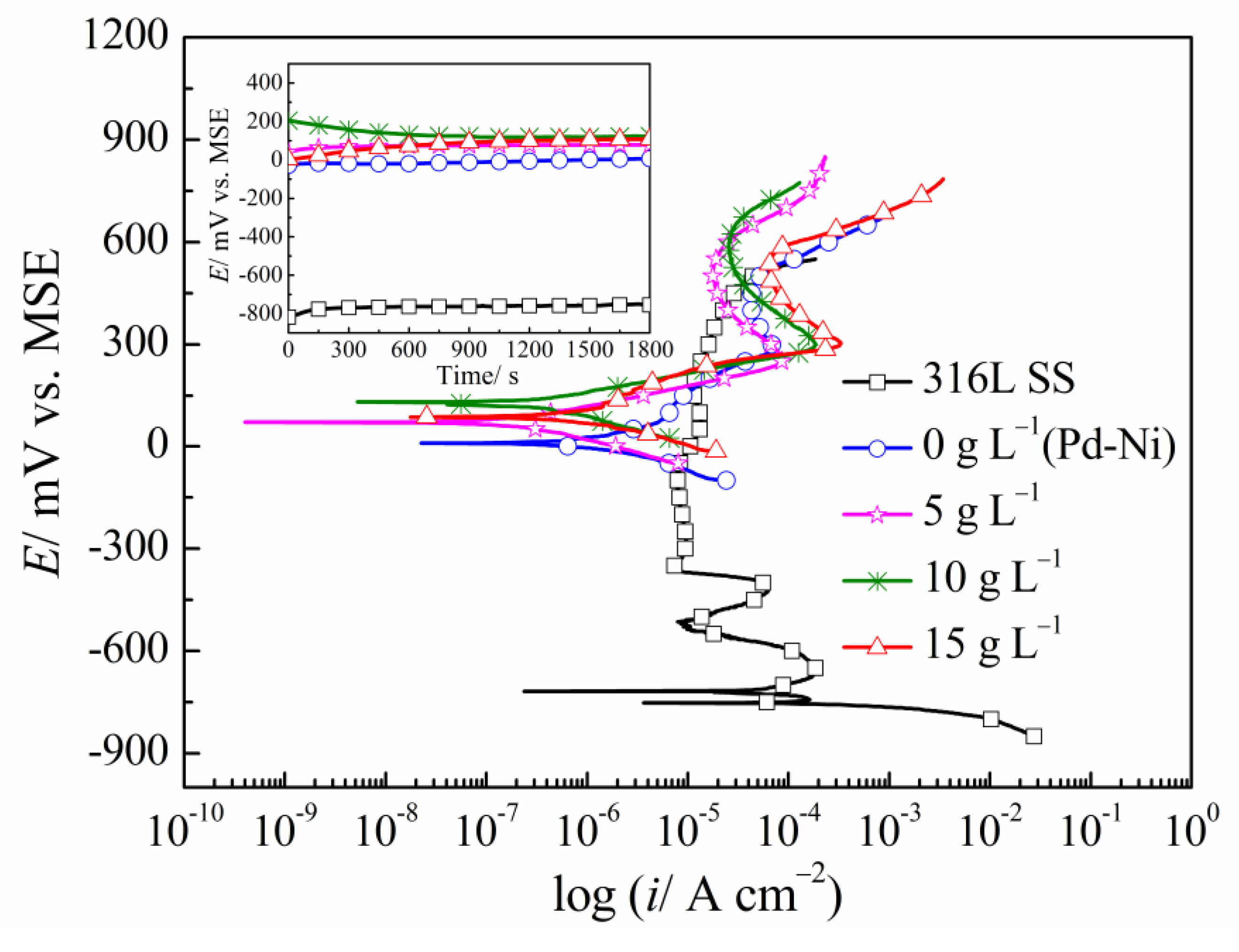
| Samples | OCP (mV vs. MSE) | Ecorr (mV vs. MSE) | icorr (×10−7 A cm−2) | βc (mV dec−1) |
|---|---|---|---|---|
| 316L SS | −721 | −750 | 882.70 | 49 |
| Pd-Ni | 5 | 10 | 13.80 | 101.19 |
| Pd-Ni/TiO2 (5 g L−1) | 78 | 71 | 2.14 | 76.48 |
| Pd-Ni/TiO2 (10 g L−1) | 122 | 140 | 2.47 | 77.82 |
| Pd-Ni/TiO2 (15 g L−1) | 106 | 101 | 7.02 | 70.87 |
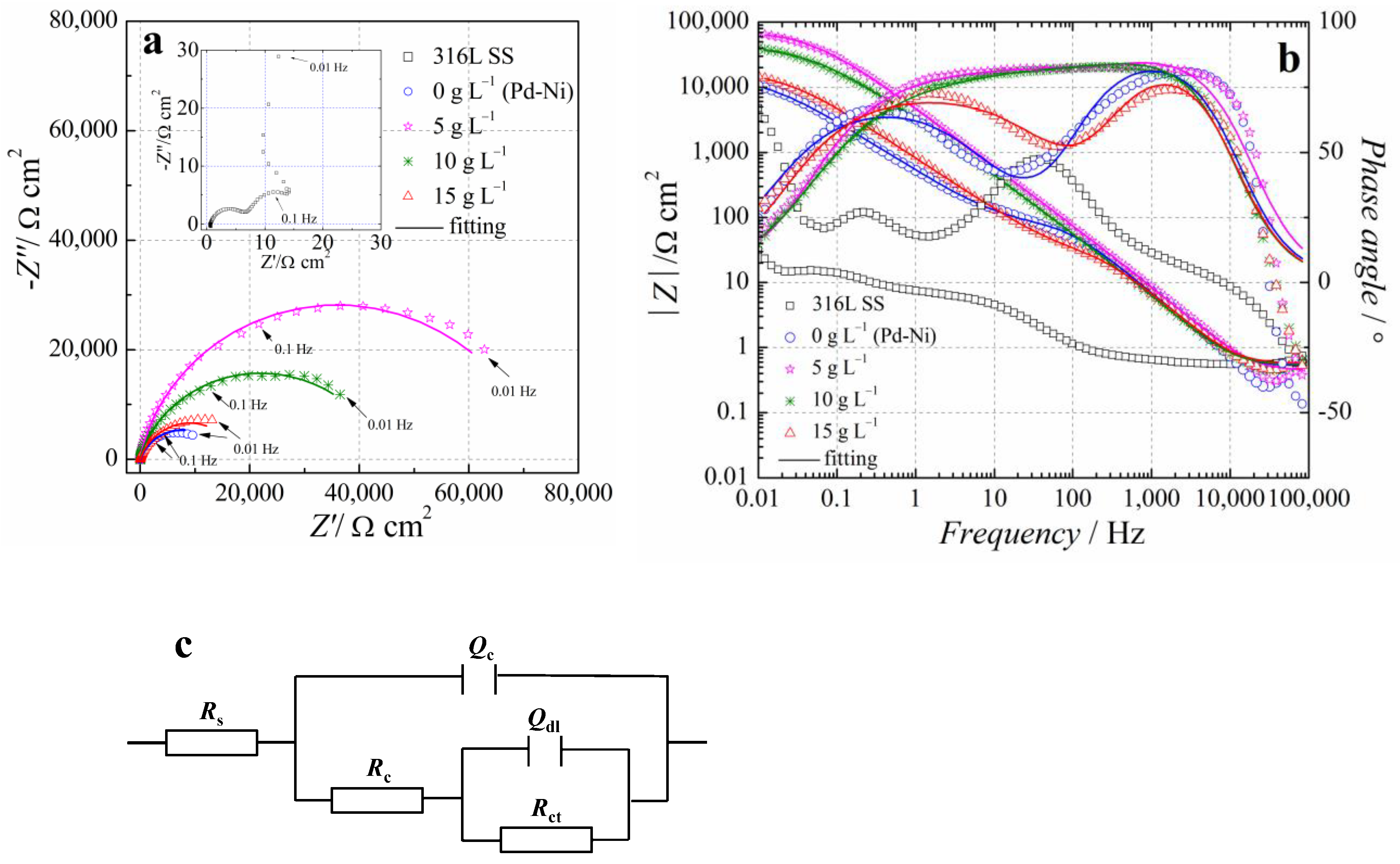
| TiO2 Content in Electrolyte (g L−1) | 0 | 5 | 10 | 15 |
|---|---|---|---|---|
| Rs (Ω cm2) | 0.526 | 0.55 | 0.61 | 0.573 |
| Qdl (Sn Ω−1 cm−2) | 3.171 × 10⁻⁵ | 2.46 × 10⁻⁵ | 2.523 × 10⁻⁵ | 3.07 × 10⁻⁵ |
| ndl | 0.965 | 0.968 | 0.95 | 0.942 |
| Rct (Ω cm2) | 90.48 | 134.1 | 111 | 97.39 |
| Qc (Sn Ω−1 cm−2) | 4.307 × 10⁻⁴ | 1.95 × 10⁻⁵ | 4.676 × 10⁻⁵ | 2.348 × 10⁻⁴ |
| nc | 0.786 | 0.671 | 0.684 | 0.793 |
| Rc (Ω cm2) | 1.442 × 10⁴ | 7.68 × 10⁴ | 4.825 × 10⁴ | 1.763 × 10⁴ |
| χ2 (10−2) | 7.73 | 4.65 | 8.42 | 2.63 |
© 2018 by the authors. Licensee MDPI, Basel, Switzerland. This article is an open access article distributed under the terms and conditions of the Creative Commons Attribution (CC BY) license (http://creativecommons.org/licenses/by/4.0/).
Share and Cite
Zhang, Z.; Tang, J.; Wang, Y.; Wang, H.; Normand, B.; Zuo, Y. Electrodeposition of a Pd-Ni/TiO2 Composite Coating on 316L SS and Its Corrosion Behavior in Hot Sulfuric Acid Solution. Coatings 2018, 8, 182. https://doi.org/10.3390/coatings8050182
Zhang Z, Tang J, Wang Y, Wang H, Normand B, Zuo Y. Electrodeposition of a Pd-Ni/TiO2 Composite Coating on 316L SS and Its Corrosion Behavior in Hot Sulfuric Acid Solution. Coatings. 2018; 8(5):182. https://doi.org/10.3390/coatings8050182
Chicago/Turabian StyleZhang, Zhiheng, Junlei Tang, Yingying Wang, Hu Wang, Bernard Normand, and Yu Zuo. 2018. "Electrodeposition of a Pd-Ni/TiO2 Composite Coating on 316L SS and Its Corrosion Behavior in Hot Sulfuric Acid Solution" Coatings 8, no. 5: 182. https://doi.org/10.3390/coatings8050182