Stabilized SPEEK Membranes with a High Degree of Sulfonation for Enthalpy Heat Exchangers


1
Department of Industrial Engineering, University of Rome Tor Vergata, 00133 Roma, Italy
2
International Associated Laboratory (L.I.A.), Ionomer Materials for Energy, 00133 Roma, Italy
3
Department of Chemistry, Biology and Biotechnology, University of Perugia, 06123 Perugia, Italy
4
Department of Engineering, University of Perugia, 06125 Perugia, Italy
*
Author to whom correspondence should be addressed.
Coatings 2018, 8(5), 190; https://doi.org/10.3390/coatings8050190
Submission received: 18 April 2018
/
Revised: 10 May 2018
/
Accepted: 16 May 2018
/
Published: 19 May 2018
(This article belongs to the Special Issue Active Organic and Organic-Inorganic Hybrid Coatings and Thin Films: Challenges, Developments, Perspectives)
Abstract
:In this investigation, we explored for the first time the use of cross-linked sulfonated poly (ether ether ketone) (SPEEK) membranes in the fabrication of enthalpy heat exchangers. SPEEK is very sensitive to changes in relative humidity, especially when featuring high degrees of sulfonation (DS), though a poor mechanical stability may be observed in the latter case. Cross-linking is crucial in overcoming this issue, and here, we firstly employed the INCA method (ionomer counter-elastic pressure “nc” analysis) to assess the improvements in the mechanical properties. The cross-link was achieved following a simple thermal-assisted process that occurs directly on the performed membranes. After an initial screening, a degree of cross-link = 0.1 was selected as the better compromise between absorption of water vapor and mechanical properties. When implemented in the enthalpy heat exchanger system, these cross-linked SPEEK membranes enabled a high level of sensible heat exchange, as well as a remarkable variation in the mass (water vapor) transfer between the individual air flows. The performances resulted in being better than those for the system based on a benchmark commercially available perfluorinated Nafion membrane.
1. Introduction
The impelling needs for a consistent reduction of pollution in large towns and CO2 emissions in the atmosphere have reinforced the interest in efficient and clean systems for homes and other buildings. In terms of the evolution of established policies, in 2014, the European Union issued Regulation 1253/2014 on eco-design requirements for ventilation units, which represents one of the measures implementing Directive 2009/125/EC, establishing a framework for the settings of design specifications for improving the environmental performance of energy-related products. In this broad context, the building sector is therefore pushed ever more towards reducing energy consumption, leading to the consequent need for improving the “indoor” insulation. On the other hand, insulation may lead to an increase in air tightness, thereby causing poor indoor environments and causing adverse effects on buildings and users. To avoid negative effects due to the lack of the air exchange, several companies proposed controlled mechanical ventilation systems, the result of which is usually associated with a heat recovery system (so-called exchanger or heat recuperator) to increase the energy efficiency of the ventilation system itself. The thermal load for ventilation systems now represents a relevant percentage of the overall energy needs, and therefore, any direct effort towards the increase in efficiency of the ventilation itself would bring significant benefits for the whole building sector. Through the installation of the aforementioned systems, it is possible to avoid the arbitrary opening action of the fixtures, pursuing the goal of energy saving by preheating the outside cold air with warm internal air at the outlet (in winter conditions) or pre-cooling the warm outdoor air with cold indoor air at the exhaust (in summer conditions). In the last few years, many systems have emerged that allow, in addition to the heat recovery, to humidify (in winter) and dehumidify (in summer) the outside air [1]. These systems are called enthalpy heat exchangers. The recovery of water vapor is particularly useful from an energy point of view, as it contributes to passively decreasing the energetic load that the air conditioning plants must support to remove water vapor in the warm season and to increase its presence in the cold season. Furthermore, the enthalpy heat exchangers show themselves to be useful for improving the indoor thermohygrometric comfort [2]. Though their structure is often rather simple, the practical applications of the enthalpy exchangers are limited. This is essentially related to the very low moisture transfer coefficient of the common vapor-permeable materials with respect to the associated cost increase, which ultimately lead to an energy recovery device with a long payback time. Most enthalpy heat exchangers make use of a membrane involving the exchange of heat while being permeable to water to guarantee the water vapor transfer [3,4,5]. Among these, ion-exchange membranes (IEM) are particularly attractive because of their effective water transport ability, which is well demonstrated in different fields, including fuel cells, flow batteries, water purification, pharmaceutical industry and the food industry [6,7,8]. Despite this fact, there is only a handful of studies in this area, mostly patented [9,10,11,12]. Perfluorinated (IEM) materials like Nafion™ [13,14,15,16,17,18] appear to be the most obvious choice, though they present important drawbacks. In 2006, the U.S. Environmental Protection Agency (EPA) demonstrated the bioaccumulative effects of several perfluoro-organic compounds featuring long perfluoro alkyl chains [19]. Many of these compounds are currently classified as substances of very high concern (SHVC) under EU Chemicals Regulation REACH [20]. Therefore, companies involved in the manufacture and marketing of fluoro-compounds are replacing long perfluorinated alkyl compounds with shorter ones. However, the shortening of the chain length of the fluorinated moiety has posed challenging technological issues because of the dramatic loss of performances such as a high degree of swelling in the presence of moisture, with consequent deterioration of mechanical properties, up to breakage [21]. The loss of performance may ultimately lead to a decrease in the heat and water vapor exchange capacity. Another limit of perfluorinated materials is their high cost (i.e., U.S. dollars 140 to 311/0.305 m × 0.305 m for Nafion™, Ion Power) [22].
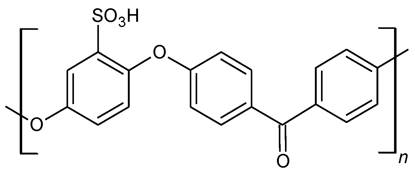
Among all the candidates for IEMs, sulfonated poly (ether ether ketone)-based (SPEEK, Figure 1) membranes are considered to be the most attractive non-perfluorinated ones [22,23,24,25].
They combine appealing properties, including high thermal and chemical stability, easy availability and low cost; on the other hand, SPEEK membranes with a high sulfonation degree (DS) can dissolve in liquid water or in particular conditions of temperature and relative humidity (RH), completely losing their mechanical properties. In 2009, some of us contributed to the development of simple and cost-effective thermal cross-linking treatments assisted by the presence of a polar aprotic solvent, i.e., dimethyl sulfoxide (DMSO), to enhance the stability and performance of SPEEK membranes. It was demonstrated that after treatments performed in air at temperatures higher than 160 °C, SPEEK membranes have a Young modulus higher (1300 MPa) than the untreated counterpart (850 MPa) and could resist water up to 145 °C without significant swelling [26,27,28]. Surprisingly, the cross-linking does not decrease the capacity of the polymer to absorb water vapor, due to a reduced tortuosity of the membrane channels, enabling a better water transport in the membrane microstructure [29]. Note that with respect to the known cross-linking processes [30,31,32,33,34,35,36,37,38], the above approach does not use cross-linking molecules, which are often sensitive to the operating conditions [39]. Moreover, the process as a whole is not-expensive, short-lived, simply realizable and is suitable for all DS values [40,41,42,43,44,45,46].
In this paper, we explore for the first time the effectiveness of cross-linked sulfonated SPEEK membranes in the fabrication of enthalpy heat exchangers. Our results demonstrated that a high level of sensible heat exchanged (the energy transfer linked to temperature variations), as well as a remarkable variation in the mass (water vapor) transfer between the individual air flows are achievable. Commercially available Nafion™ NRE-212 was also considered for comparative purposes.
2. Materials and Methods
2.1. Materials
PEEK (Victrex 450P, molecular weight MW = 38,300 g/mol, 132 repeat units per mole) was supplied by Solvay (Brussels, Belgium). Nafion™ NRE-212 (equivalent weight EW = 1100 g/eq, ion exchange capacity (IEC) = 0.91 meq/g) were supplied by Sigma-Aldrich (St. Louis, MO, USA). Dimethyl sulfoxide (DMSO) and all the other reagents and materials were purchased from Carlo Erba RP (Milan, Italy).
2.2. Membrane Preparation
SPEEK was prepared by the reaction of poly(ether ether ketone) (PEEK) with concentrated sulfuric acid (95%–98%), under N2 at 50 °C for 2–4 days, following a previously-reported procedure [47]. A DS in the range 0.7–1.0, depending on the reaction time, was obtained. The solution was poured, under continuous stirring, into an excess of ice-cold water obtaining a white precipitate. After resting overnight, the precipitate was filtered and washed with water several times, using a dialysis membrane (Sigma–Aldrich D9402), to neutral pH to eliminate the residual sulfuric acid completely. The sulfonated polymer (SPEEK) was then dried over night at 80 °C. The polymers were dissolved in dimethyl sulfoxide (DMSO) at 80–90 °C. The ratio polymer: DMSO was 1:10 (mg/mL). After evaporation to ~1/3 of the original volume, the solution was spread on a glass plate, using doctor blade-type equipment and then heated in the oven for the casting treatment at different times (15–24 h) and temperatures (90–120 °C). After the casting, membranes were stored at ambient relative humidity and peeled off. Membranes treated at 120 °C for 24 h (in the following 120–24) were placed on a Teflon substrate and put in the ventilated oven at 180 °C (cross-linking procedure, called in the following XL SPEEK) for different times in the range 3–24 h depending on the desired crosslinking degree (DXL) [27,40]. After the preparation, all the membranes were immersed at room temperature in a solution of H2O2 3% for 1 h, then in H2SO4 5 M for 1 h and rinsed off with water. The membrane thickness was 20 μm.
2.3. Membrane Characterization
2.3.1. Ion Exchange Capacity Measurements
The ion exchange capacity (IEC in milliequivalents/gram) was measured by titration [27]. To eliminate DMSO, which can affect IEC, membranes were swelled in water at 100 °C for 5 h, followed by treatment in H2SO4 5 M at room temperature for 2 h and then washed until neutral pH before the titration.
The degree of crosslinking (DXL) for treated samples was evaluated measuring the IEC using the following formula:
where refers to the ion exchange capacity before the treatments and refers to the ion exchange capacity after the treatments at 180 °C.
2.3.2. Water Uptake
Membrane samples dried over P2O5 for 3 days were weighed and then immersed for 24 h in liquid water in a closed Teflon vessel at a constant temperature. After the immersion, the membranes were equilibrated at 25 °C in water for 24 h. The excess of water was carefully wiped off, and the membrane mass was determined :
The hydration number λ was calculated as:
where n is the mol of water per mol of the sulfonic group, M the molar mass of water and IEC the ion exchange capacity. The uncertainty in the measurements was ~±0.5.
2.3.3. Counter-Elastic Pressure (nc) Measurements
2.3.4. Membrane Density, Volume
A portion of the membrane (~15 mm × 15 mm) was first dried for one day over P2O5 at room temperature and then the weight and the a, b and c dimensions accurately determined by a micrometer. The dried membrane was immersed in bi-distilled water at 20 °C and equilibrated for 24 h, then the weight and a, b and c dimensions were again determined [14,48].
2.3.5. DMA
The dynamic mechanical analysis (DMA) analysis was performed from 30–250 °C in air on the DMA 2980 dynamic analyzer (TA Instrument, New Castle, DE, USA). The frequency was fixed (1 Hz) with 0.05 N initial static force and an oscillating amplitude of 10 μm [40].
2.3.6. Enthalpy Heat Exchanger
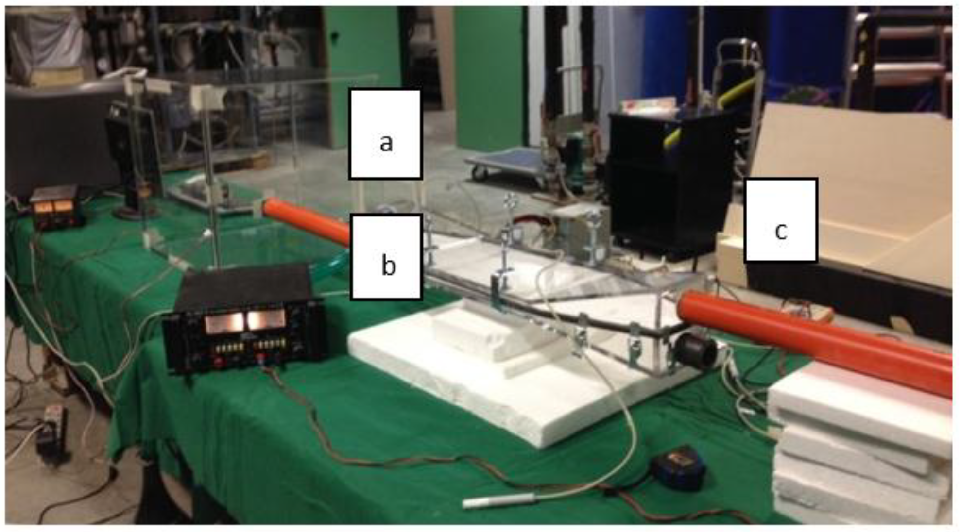
A simplified model of the basic unit of the enthalpy heat exchanger has been constructed (Figure 2, experimental apparatus, and Figure 3, scheme of the enthalpy heat exchanger of the experimental apparatus). The main components of the test bench are shown in Figure 4: the humidification chamber (a), which consists of a Pexiglass vessel measuring 50 cm × 50 cm × 50 cm, with an opening side for the positioning of the suction fans (b) and connected, through a soft mobile tube, to an ultrasonic humidifier, which allows one to control the temperature and relative humidity conditions at the inlet of the exchanger (c), varying them within the characteristic intervals of the applications related to the air treatment in buildings [50]. The membranes used are: plastic materials, Nafion NRETM 212, XL SPEEK (DXL = 0.1, DSinit = 0.9).
3. Results and Discussion
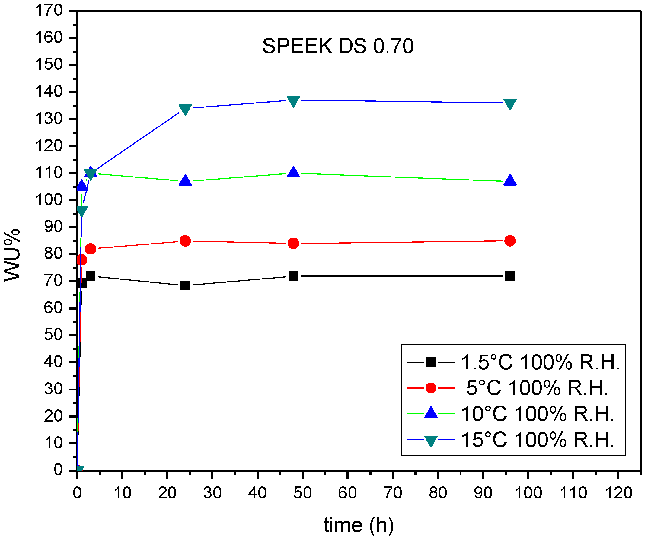
The measurements on the test bench described in the Materials and Methods were performed on XL SPEEK membranes due to the instability of membranes without treatment, as explained below. The water uptake (WU) was measured at different temperatures and times in liquid water on SPEEK membranes with DS = 0.70 and 0.9 treated in oven at 90 °C for 24 h (90–24) or 120 °C for 15 h (120–15). The kinetics of the water uptake and the time where the equilibrium is reached depend very much on the DS. For SPEEK with DS = 0.70, WU kinetics were made at different temperatures from 1.5–15 °C; at 20 °C, the material begins to show an excessive swelling. It is not possible to perform kinetic measurements in the same conditions for SPEEK with DS = 0.9 (90–24), because of the solubilization of the material after 5 h. Figure 5 shows that for SPEEK 0.70 (90–24), the water uptake kinetics at 1.5 °C is very fast and reached the stationary value after only 5 h of hydration with a final WU = 70% corresponding to a λ value of 20 (Table 1). The material reaches equilibrium rapidly (5–10 h) at low temperatures, while the equilibrium is shifted to larger times with increasing temperature (at 15 °C around 40 h). This behavior is similar to that observed for Nafion NRE-212 (EW 1100), where the material is subjected to two processes: the first one is rapid, and it is due to the diffusion of water inside the membranes; the second one is slower, and it is related to irreversible changes of chain conformations [50].
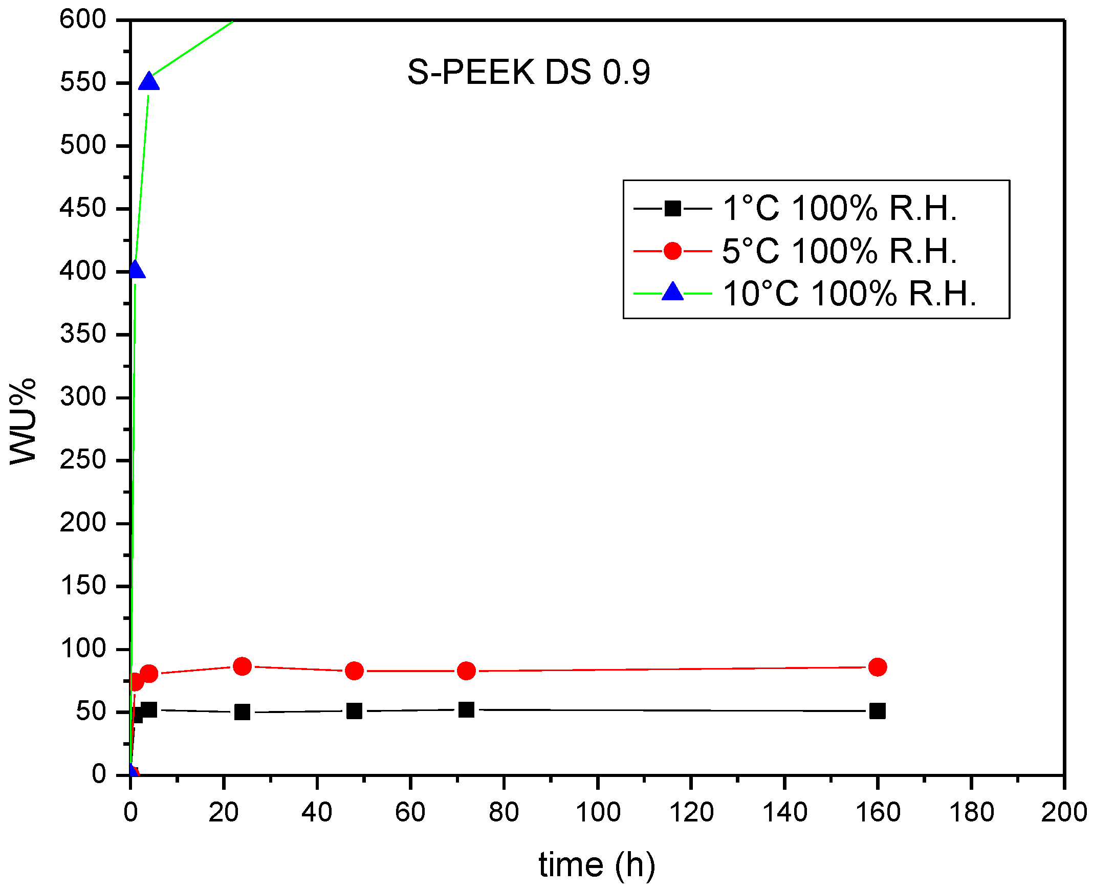
A heat treatment at 120 °C for 15 h was performed in order to decrease the free volume between the chains, for the improvement of the hydrophilic stability of SPEEK with DS = 0.9, which presents a large swelling even at a low temperature. After the treatment, the material begins to solubilize at 10 °C and no more at 1 °C, due to the annealing effect (Figure 6 and Table 2).
Figure 7 shows lambda (λ) values for SPEEK with DXL = 0.22 measured after swelling in water at 100 °C for different times and equilibrated at room temperature for 24 h. We can recognize two processes: an initial and fast one and a slower one. The latter is probably due to the slow morphological change of the backbone.
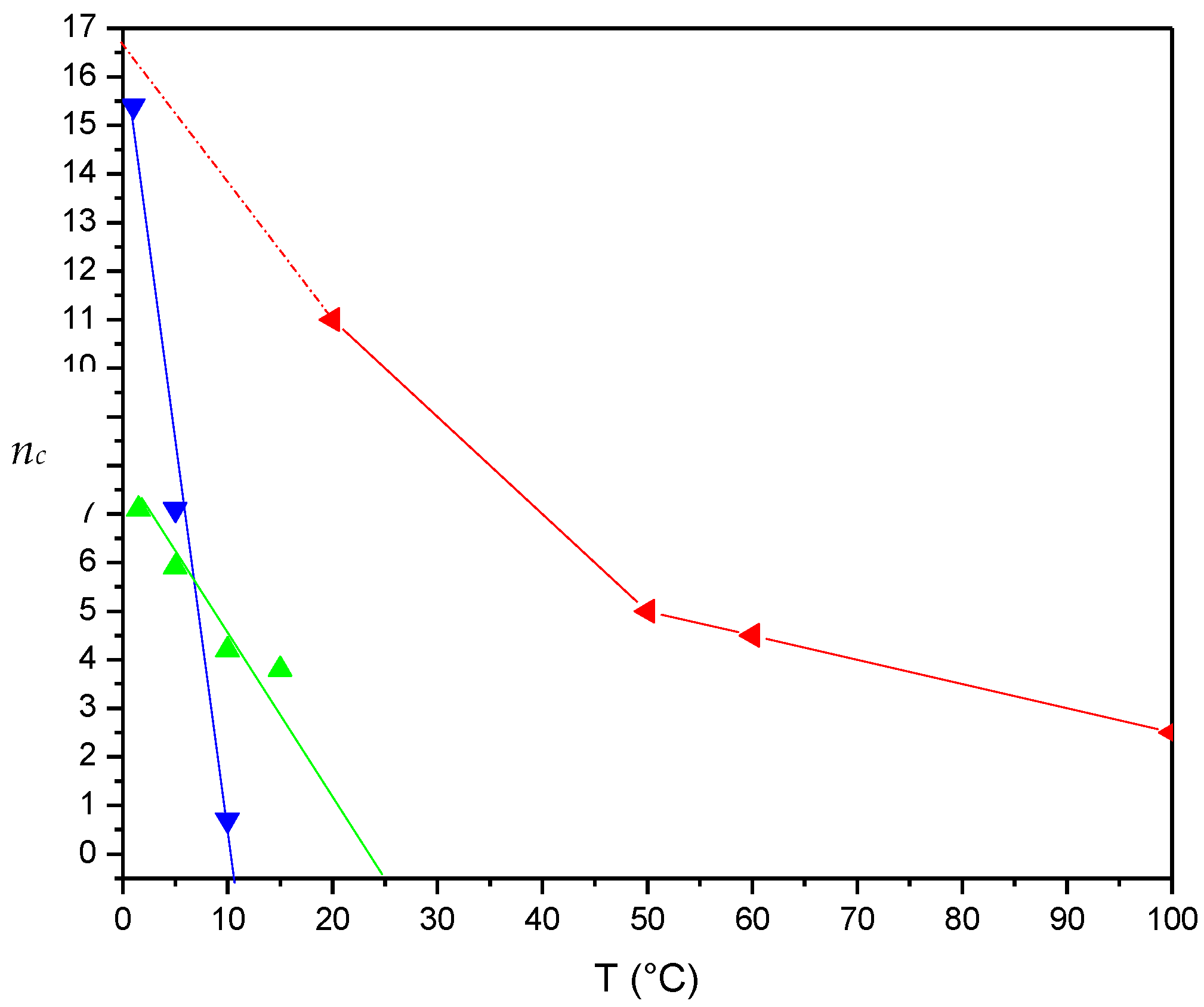
In Figure 8 is reported an application of the INCA method (ionomer nc analysis). The INCA method is based on the use of nc/T plots to derive important properties of the ionomer, such as the degree of crystallinity, mechanical properties, glass transition and melting temperature. The nc vs. temperature graph shows that membranes completely lose their mechanical properties (nc = 0), and they present infinite swelling already at 10 °C for SPEEK with DS 0.9 and at 25 °C with DS 0.7. The weak van deer Waals forces inside the macromolecular chains, which are broken at low temperatures, and the presence of a larger number of sulfonic groups, which determine a greater absorption of water, are responsible for the previous behavior [21,49]. The presence of covalent bonds in the XL derivative (Figure 9) completely changes this trend, improving the resistance in water.
As already discussed before, the nc analysis allowed evaluating the mechanical properties. A comparison of the results was also made using stress strain tests. The Tg values were determined with the dynamic mechanical analysis (DMA). It can be seen that the intrinsic values of Tg of SPEEK are very high and therefore suitable for use in all environmental conditions. The results are shown in Table 3.
In general, Young’s modulus (E, stiffness) characterizes the elastic domain of polymers, where weak inter-chain bonds are observed at the microscopic scale; this could be related to fundamental bond properties. Stiffness explores essentially low displacements such as (a) van der Waals bonds (the change of the distance between chains and of dipole-dipole interactions), (b) defects, such as entanglements, and (c) the presence of solvents, such as water and DMSO. Yield stress (YS) and tensile strength (TS) are instead related to strong bonds, including covalent cross-links between macromolecular chains, and they constitute macroscopic scale properties. Tensile strength and yield stress explore large displacements (plasticity). It is evident from the mechanical measurements that the thermal treatment at 180 °C enhances significantly the membrane mechanical properties: the elastic modulus, the ultimate tensile strength and the yield stress all increase significantly by XL increasing. It can be seen that the elongation at break of the membrane with DXL = 0.10 is good and keeps a value close to the SPEEK with DXL = 0 (ductile behavior), which corresponds to a greater plasticity and malleability of the material. For greater degrees of XL, the value is typical of brittle polymers. If we assume that the mechanical degradation of membranes is related to the existence of plastic deformation during the operation, the enhancement of mechanical properties is of major importance for the improvement of membrane durability. Table 4 reports the WU and the swelling parameters for SPEEK 0.9. Only the XL treatment allows avoiding the complete dissolution of the material.
Due to the presence of the XL, it is possible to use high values of DS that allow the material to acquire a great sensitivity to changes in relative humidity, since the tendency to absorb water is proportional to the number of sulfonic groups per repeating unit. From the point of view of applications in heat exchangers, it is interesting to note that the capacity to adsorb water does not change significantly until RH = 80% for XL and non-XL derivatives (Table 5).
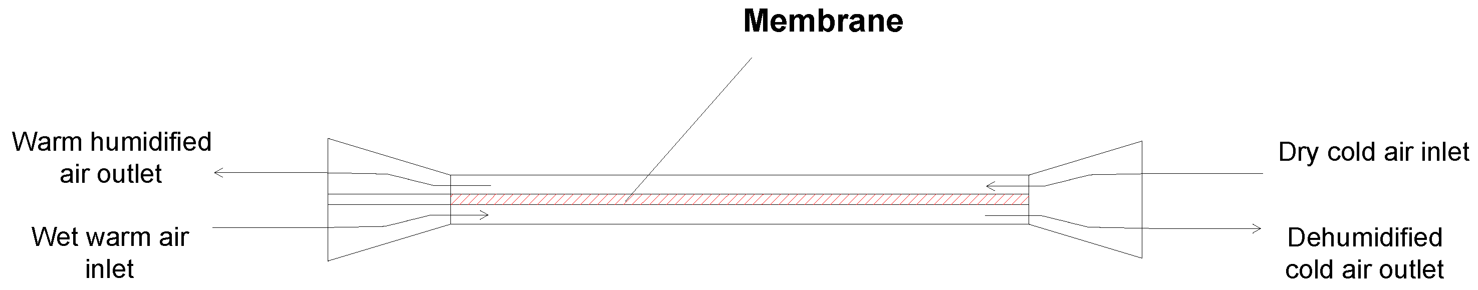
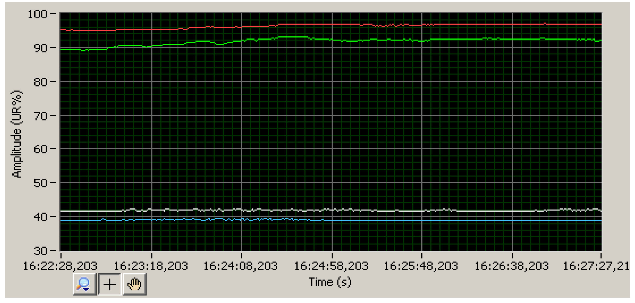
The effectiveness of SPEEK membranes for heat exchangers was explored on a simplified geometry (flat plate) (see Materials and Methods). In the proposed experimental apparatus (Figure 4), it is therefore possible to fix the temperature and relative humidity conditions of the two air flows, controlling also the flow rate, with the aim of evaluating the capacity of membranes to transfer heat and humidity. The operating scheme of the test bench is as follows: in the humidification chamber, humid and warm air are produced to simulate the outdoor air conditions in the summer. The flow of the air drawn from the said chamber will constitute the air flow rate that will have to exchange heat and water vapor with the dry and wet flow coming from the inlet. The two flows are sent to the exchanger and, excluding the initial part of the convergent, will carry out the heat and mass exchange, mainly in correspondence with the membrane under examination. The polymer membrane is therefore lapped on both sides by the two flows at known temperature and relative humidity, measured at the inlet and at the outlet of the heat exchanger itself through four sensors (Galltec-Mela, L series). Data are acquired through a program developed in the Labview environment, which allows saving, processing and graphic representation. From the physical point of view, the heat given off by the hot fluid will be given by its thermal capacity for the decrease in temperature that it undergoes along the passage on the membrane; the water vapor yielded will instead be given by the reduction in absolute humidity contained in the air flow (absolute humidity is the ratio between the mass of water and the mass of dry air contained in a given volume of humid air). The opposite will happen for cold and dry fluid. The relative humidity is, together with the temperature, the thermohygrometric parameter most closely linked to the well-being of people in the indoor environment and is also the simplest parameter to measure with the available instruments. Since the temperature and relative humidity of air can be traced back to its water content, analyses of temperature variation and relative humidity in the test bench were carried out to measure the performance of the exchanger. The verification of the thermohygrometric exchange efficiency can be carried out both through the separate evaluation of temperature and relative humidity variations. The results are shown in Figure 10, Figure 11, Figure 12 and Figure 13. The test bench was tested with a sheet of waterproof plastic material, in order to validate the experimental apparatus. The first experimental test was carried out with a flow of hot (31.4 °C) and humid air (relative humidity 95%) at the entrance (green line of Figure 10, red line of Figure 11 and point P1 of Figure 12) and a corresponding flow of cold (26.3 °C) and dry (38% relative humidity) air entering from the opposite side of the heat exchanger (gray line of Figure 10, light blue line of Figure 11 and point P1 of Figure 13) [50].
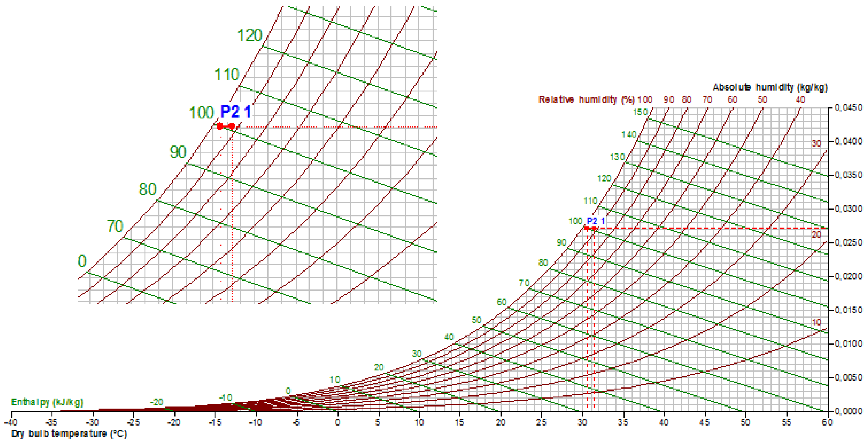
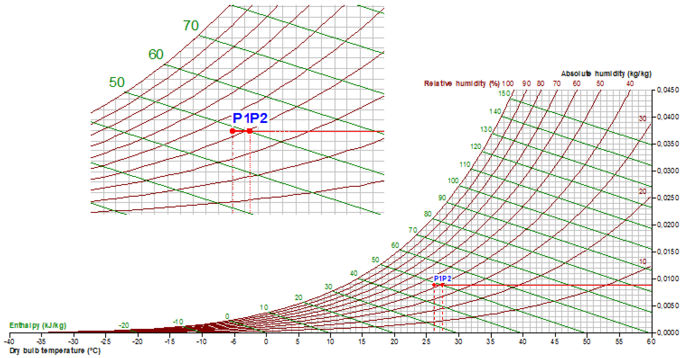
Changes in temperature and water content can be viewed even more immediately through the use of the psychrometric diagram (Figure 12 and Figure 13). In this kind of graph, the temperature of the humid air is shown in the abscissa, in the right-hand ordinate the absolute humidity (in g of water/kg of dry air) and in the curves (in red) running from the bottom side to left to the upper right part, the relative humidity. By fixing two of these three parameters, the thermodynamic status of the humid air can be defined. Thanks to the results, it can be seen how the plastic material allows, as expected, the transfer of sensible heat between the two flows (section P1–P2 of the curves in Figure 12 and Figure 13, which testify to the temperature variations), without allowing the exchange of the specific humidity (both P1–P2 sections are horizontal, that is at constant absolute humidity) [50].
The test was repeated under similar conditions with a membrane of Nafion™ NRE-212 as a comparative reference (Figure 14 and Figure 15). In addition to heat transfer (temperature variations), it is also possible to highlight the transport of water vapor, by modifying absolute humidity in the P1–P2 section of the curves (increasing in the dry stream, decreasing in the wet stream). As an example, the wet flow passes, from 0.0260–0.0245 g/kg, with an absolute humidity decrease equal to 0.0015 g/kg [50].
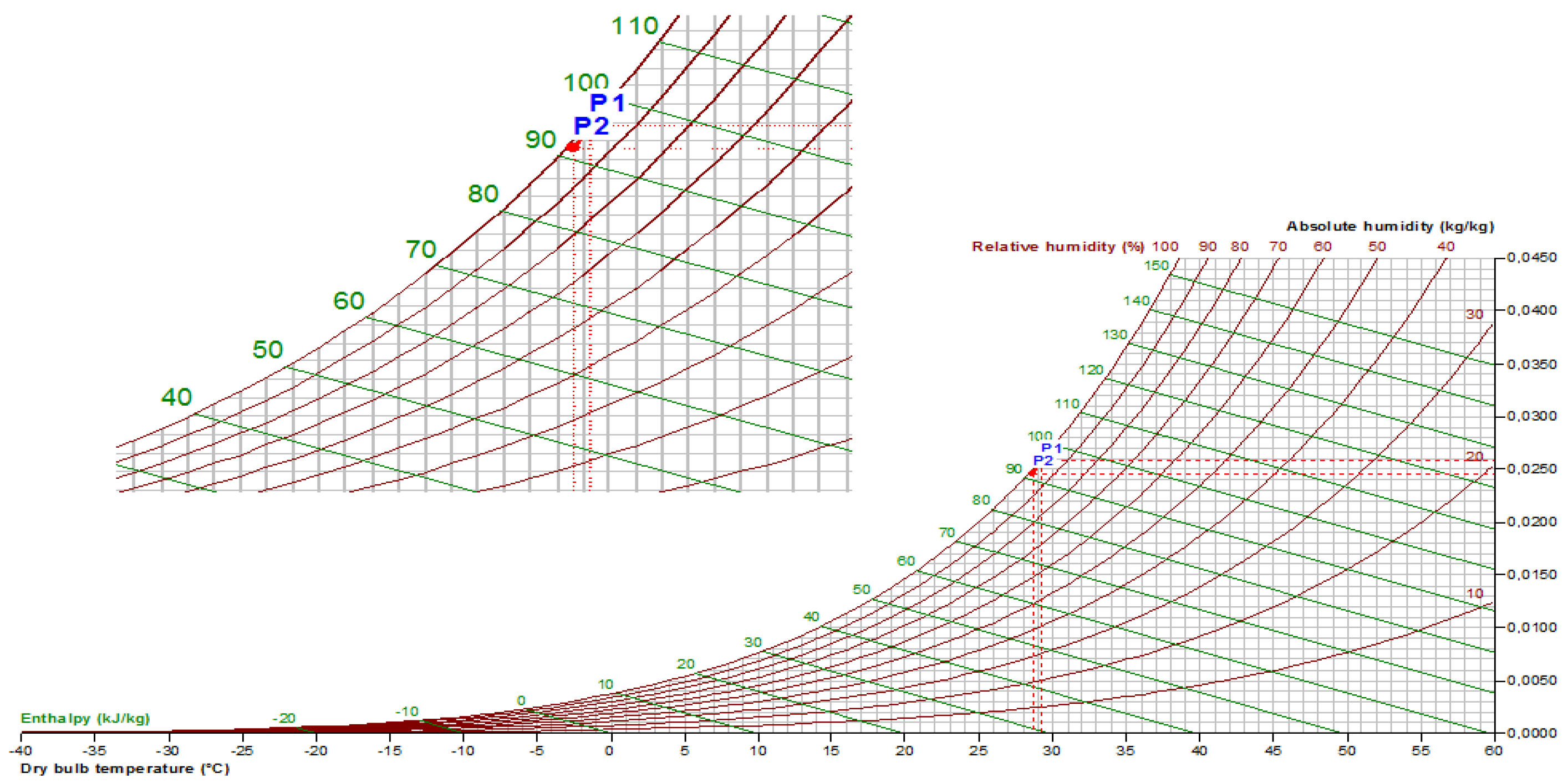
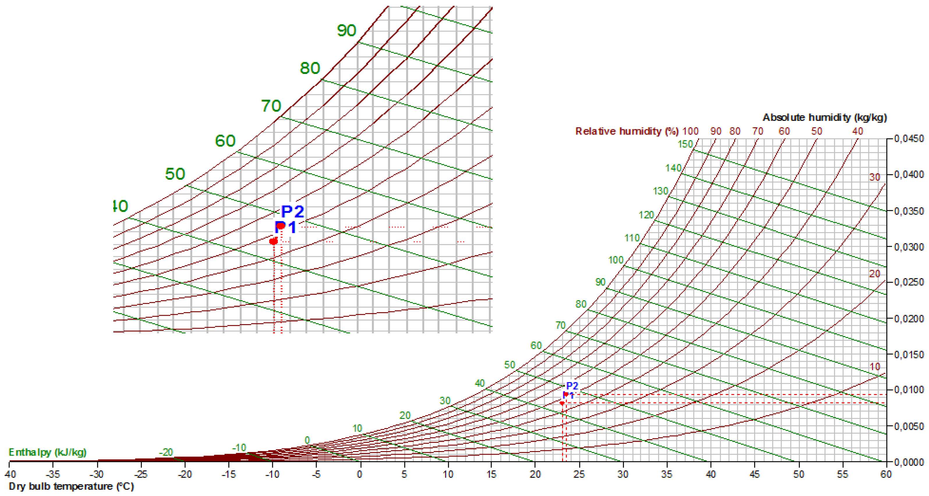
The test was finally repeated with a low cross-linked SPEEK-based membrane (DXL = 0.1, DSinit = 0.9, IECinit = 2.5 meq/g, 20 μm). This XL value represents the best compromise between water uptake and mechanical properties. The short treatment time (3 h) gives the possibility to produce XL-SPEEK at an industrial scale, where in addition to reliability and performance, the processing time is very important. Figure 16 and Figure 17 show the results obtained. The graphs show that in the passage through the SPEEK membrane, the two air flows exchanged sensible heat, as the temperature variations indicate. Changes in absolute humidity testify, on the other hand, the exchange of mass (water vapor) between the two flows through the membrane, according to the equations previously described. The effectiveness of SPEEK as a membrane in enthalpy heat exchangers is therefore demonstrated. Moreover, it is possible to observe the higher slope of the P1–P2 sections in the tests carried out with cross-linked SPEEK, with respect to the slope of the P1–P2 sections of Nafion ™ with EW = 1100 g/mol, resulting in a more marked variation of the content of water vapor for the individual air flows, so demonstrating the higher performance of SPEEK in terms of water vapor exchange. In fact, the wet flow in this case passes, from 0.0250–0.0230 g/kg, with an absolute humidity decrease equal to 0.0020 g/kg (0.0015 g/kg for Nafion™) [50].
4. Conclusions
In this paper, the use of cross-linked SPEEK membranes in the realization of enthalpy heat exchanger systems was proposed for the first time. SPEEK with DS = (0.7–0.9) has very high water uptake with very fast kinetics. Unfortunately, for use in HVAC systems, it is not suitable due to the insufficient mechanical properties (nc = 0, INCA method) even at low temperatures and high humidity values, conditions that usually occur. Thanks to our cross-linking method, we were able to stabilize these materials modulating the grade of XL with different times of treatment. SPEEK membranes were tested in acid form with an initial IECinit = 2.5 meq/g (DSinit = 0.9) and a time of treatment of 3 h at 180 °C, corresponding to a DXL = 0.1. These conditions of use represent the best compromise between the water uptake and the mechanical properties. By this design concept, the enthalpy exchangers based on cross-linked SPEEK showed a higher slope of the P1–P2 sections, with respect to the slope of the P1–P2 sections of Nafion™, resulting in a more marked variation of the content of water vapor for the individual air flows. The wet flow in this case passes, from 0.0250–0.0230 g/kg, with an absolute humidity decrease equal to 0.0020 g/kg (0.0015 g/kg for Nafion™). These results are very promising for the utilization of XL SPEEK for enthalpy heat exchangers, in air conditioning applications. The future work will deal with the optimization of membrane shaping to form channels for the enthalpy heat exchangers, both in terms of the geometric section and patterns of air flow.
5. Patents
Patent pending: Di Vona, M.L.; Baldinelli, G.; Marrocchi, A.; Narducci, R. Scambiatori di Calore Entalpici a membrane di Tipo Polimerico Aromatic Solfonato e Procedimento per la Preparazione di Dette Membrane. Domanda numero: 102016000112268, 8 November 2016. (In Italian).
Author Contributions
R.N. and G.B. conceived of, designed and performed the experiments. R.N., G.B., A.M. and M.L.D.V. analyzed the data. G.B., A.M. and M.L.D.V. contributed reagents/materials/analysis tools. R.N. wrote the paper.
Funding
This research received no external funding.
Conflicts of Interest
The authors declare no conflict of interest.
References
- Reay, D.A. Heat Recovery Systems; E & F.N. Span: London, UK, 1979. [Google Scholar]
- Fernandez-Seara, J.; Diz, R.; Uhia, F.J.; Dopazo, A.; Ferro, J.M. Experimental analysis of an air-to-air heat recovery unit for balanced ventilation systems in residential buildings. Energy Convers. Manag. 2011, 52, 635–640. [Google Scholar] [CrossRef]
- Al-Waked, R.; Nasif, M.S.; Morrison, G.; Behnia, M. CFD simulation of air to air enthalpy heat exchanger: Variable membrane moisture resistance. Appl. Therm. Eng. 2015, 84, 301–309. [Google Scholar] [CrossRef]
- Woods, J. Membrane processes for heating, ventilation, and air conditioning. Renew. Sustain. Energy Rev. 2014, 33, 290–304. [Google Scholar] [CrossRef]
- Zhang, L.Z.; Liang, C.H.; Pei, L.X. Heat and moisture transfer in application scale parallel-plates enthalpy exchangers with novel membrane materials. J. Membr. Sci. 2008, 325, 672–682. [Google Scholar] [CrossRef]
- Xu, T.W. Ion exchange membranes: State of their development and perspective. J. Membr. Sci. 2005, 263, 1–29. [Google Scholar] [CrossRef]
- Daufin, G.; Escudier, J.P.; Carrere, H.; Berot, S.; Fillaudeau, L.; Decloux, M. Recent and emerging applications of membrane processes in the food and dairy industry. Food Bioprod. Process. 2001, 79, 89–102. [Google Scholar] [CrossRef]
- Tarvainen, T.; Svarfvar, B.; Akerman, S.; Savolainen, J.; Karhu, M.; Paronen, P.; Jarvinen, K. Drug release from a porous ion-exchange membrane in vitro. Biomaterials 1999, 20, 2177–2183. [Google Scholar] [CrossRef]
- Dobbs, G.M.; Freihaut, J.D. Plate-Type Heat Exchanger. U.S. Patent 6684943B2, 3 February 2004. [Google Scholar]
- Dobbs, G.M.; Benoit, J.T.; Lemcoff, N.O. Droplet Actuator Devices and Methods. WO2010/002957 A2, 1 July 2010. [Google Scholar]
- Ehrenberg, S.G.; Huynh, H.; Johnson, B. Enhanced HVAC System and Method. U.S. Patent 8470071, 25 June 2013. [Google Scholar]
- Dean, F.J.; Kadylak, D.E.; Huizing, R.N.; Balanko, J.B.; Mullen, C.W. Counter-Flow Energy Recovery Ventilator (ERV) Core. WO2013/091099 A1, 27 June 2013. [Google Scholar]
- Alberti, G.; Narducci, R.; Di Vona, M.L.; Giancola, S. More on Nafion Conductivity Decay at Temperatures Higher than 80 °C: Preparation and First Characterization of In-Plane Oriented Layered Morphologies. Ind. Eng. Chem. Res. 2013, 52, 10418–10424. [Google Scholar] [CrossRef]
- Alberti, G.; Di Vona, M.L.; Narducci, R. New results on the visco-elastic behaviour of ionomer membranes and relations between T-RH plots and proton conductivity decay of Nafion (R) 117 in the range 50–140 °C. Int. J. Hydrogen Energy 2012, 37, 6302–6307. [Google Scholar] [CrossRef]
- Alberti, G.; Narducci, R.; Di Vona, M.L. Solid State Proton Conductors: Properties and Applications in Fuel Cells; Knauth, P., Di Vona, M.L., Eds.; Wiley: Hoboken, NJ, USA, 2012. [Google Scholar]
- Mauritz, K.A.; Moore, R.B. State of understanding of Nafion. Chem. Rev. 2004, 104, 4535–4585. [Google Scholar] [CrossRef] [PubMed]
- Roberti, E.; Carlotti, G.; Cinelli, S.; Onori, G.; Donnadio, A.; Narducci, R.; Casciola, M.; Sganappa, M. Measurement of the Young’s modulus of Nafion membranes by Brillouin light scattering. J. Power Sources 2010, 195, 7761–7764. [Google Scholar] [CrossRef]
- Yang, H.R.; Zhang, J.; Li, J.L.; Jiang, S.P.; Forsyth, M.; Zhu, H.J. Proton Transport in Hierarchical-Structured Nafion Membranes: A NMR Study. J. Phys. Chem. Lett. 2017, 8, 3624–3629. [Google Scholar] [CrossRef] [PubMed]
- Buck, R.C.; Franklin, J.; Berger, U.; Conder, J.M.; Cousins, I.T.; Voogt, P.D.; Jensen, A.A.; Kannan, K.; Mabury, S.A.; Leeuwen, S.P.V. Perfluoroalkyl and polyfluoroalkyl substances in the environment: terminology, classification, and origins. Integr. Environ. Assess. Manag. 2011, 7, 513–541. [Google Scholar] [CrossRef] [PubMed]
- Identification of Substances of Very High Concern (SVHC) under the ‘Equivalent Level of Concern’ Route (REACH Article 57(f))—Neurotoxicants and Immunotoxicants as Examples; EUR Scientific and Technical Research Reports; Publications Office of the European Union: Rue Mercier, Luxembourg, 2015. [CrossRef]
- Alberti, G.; Narducci, R.; Sganappa, M. Effects of hydrothermal/thermal treatments on the water-uptake of Nafion membranes and relations with changes of conformation, counter-elastic force and tensile modulus of the matrix. J. Power Sources 2008, 178, 575–583. [Google Scholar] [CrossRef]
- Alberti, G.; Narducci, R.; Di Vona, M.L.; Giancola, S. Annealing of Nafion 1100 in the Presence of an Annealing Agent: APowerful Method for Increasing Ionomer Working Temperature in PEMFCs. Fuel Cells 2013, 13, 42–47. [Google Scholar] [CrossRef]
- Potreck, J. Membranes for Flue Gas Treatment. Ph.D. Thesis, University of Twente, Enschede, The Netherlands, 2009. [Google Scholar]
- Sgreccia, E.; Chailan, J.F.; Khadhraoui, M.; Di Vona, M.L.; Knauth, P. Mechanical properties of proton-conducting sulfonated aromatic polymer membranes: Stress-strain tests and dynamical analysis. J. Power Sources 2010, 195, 7770–7775. [Google Scholar] [CrossRef]
- Barbieri, G.; Brunetti, A.; Di Vona, M.L.; Sgreccia, E.; Knauth, P.; Hou, H.Y.; Hempelmann, R.; Arena, F.; Beretta, L.D.; Bauer, B.; et al. LoLiPEM: Long life proton exchange membrane fuel cells. Int. J. Hydrogen Energy 2016, 41, 1921–1934. [Google Scholar] [CrossRef]
- Di Vona, M.L.; Sgreccia, E.; Licoccia, S.; Alberti, G.; Tortet, L.; Knauth, P. Analysis of Temperature-Promoted and Solvent-Assisted Cross-Linking in Sulfonated Poly(ether ether ketone) (SPEEK) Proton-Conducting Membranes. J. Phys. Chem. B 2009, 113, 7505–7512. [Google Scholar] [CrossRef] [PubMed] [Green Version]
- Maranesi, B.; Hou, H.; Polini, R.; Sgreccia, E.; Alberti, G.; Narducci, R.; Knauth, P.; Di Vona, M.L. Cross-Linking of Sulfonated Poly(ether ether ketone) by Thermal Treatment: How Does the Reaction Occur? Fuel Cells 2013, 13, 107–117. [Google Scholar] [CrossRef] [Green Version]
- Rammler, D.H.; Zaffaroni, A. Biological implications of DMSO based on a review of its chemical properties. Ann. N. Y. Acad. Sci. 1967, 141, 13–23. [Google Scholar] [CrossRef] [PubMed]
- Di Vona, M.L.; Pasquini, L.; Narducci, R.; Pelzer, K.; Donnadio, A.; Casciola, M.; Knauth, P. Cross-linked sulfonated aromatic ionomers via SO2 bridges: Conductivity properties. J. Power Sources 2013, 243, 488–493. [Google Scholar] [CrossRef]
- Kerres, J.A. Blended and cross-linked ionomer membranes for application in membrane fuel cells. Fuel Cells 2005, 5, 230–247. [Google Scholar] [CrossRef]
- Kerres, J.A.; Xing, D.M.; Schonberger, F. Comparative investigation of novel PBI blend ionomer membranes from nonfluorinated and partially fluorinated poly arylene ethers. J. Polym. Sci. Part B Polym. Phys. 2006, 44, 2311–2326. [Google Scholar] [CrossRef]
- Bhattacharya, A.; Rawlins, J.W.; Ray, P. Polymer Grafting and Crosslinking; Wiley: Hoboken, NJ, USA, 2008. [Google Scholar]
- Huang, R.Y.M.; Shao, P.H.; Burns, C.M.; Feng, X. Sulfonation of poly(ether ether ketone)(PEEK): Kinetic study and characterization. J. Appl. Polym. Sci. 2001, 82, 2651–2660. [Google Scholar] [CrossRef]
- Shibuya, N.; Porter, R.S. Kinetics of peek sulfonation in concentrated sulfuric-acid. Macromolecules 1992, 25, 6495–6499. [Google Scholar] [CrossRef]
- Deluca, N.W.; Elabd, Y.A. Polymer electrolyte membranes for the direct methanol fuel cell: A review. J. Polym. Sci. Part B Polym. Phys. 2006, 44, 2201–2225. [Google Scholar] [CrossRef]
- Jiang, R.C.; Kunz, H.R.; Fenton, J.M. Investigation of membrane property and fuel cell behavior with sulfonated poly(ether ether ketone) electrolyte: Temperature and relative humidity effects. J. Power Sources 2005, 150, 120–128. [Google Scholar] [CrossRef]
- Astill, T.; Xie, Z.; Shi, Z.Q.; Navessin, T.; Holdcroft, S. Factors Influencing Electrochemical Properties and Performance of Hydrocarbon-Based Electrolyte PEMFC Catalyst Layers. J. Electrochem. Soc. 2009, 156, B499–B508. [Google Scholar] [CrossRef]
- Chen, J.H.; Li, D.R.; Koshikawa, H.; Asano, M.; Maekawa, Y. Crosslinking and grafting of polyetheretherketone film by radiation techniques for application in fuel cells. J. Membr. Sci. 2010, 362, 488–494. [Google Scholar] [CrossRef]
- Fontananova, E.; Brunetti, A.; Trotta, F.; Biasizzo, M.; Drioli, E.; Barbieri, G. Stabilization of Sulfonated Aromatic Polymer (SAP) Membranes Based on SPEEK-WC for PEMFCs. Fuel Cells 2013, 13, 86–97. [Google Scholar] [CrossRef]
- Di Vona, M.L.; Sgreccia, E.; Narducci, R.; Pasquini, L.; Hou, H.; Knauth, P. Stabilized sulfonated aromatic polymers by in situ solvothermal cross-linking. Front. Energy Res. 2014, 2, 39. [Google Scholar] [CrossRef]
- Narducci, R.; Di Vona, M.L.; Knauth, P. Cation-conducting ionomers made by ion exchange of sulfonated poly-ether-ether-ketone: Hydration, mechanical and thermal properties and ionic conductivity. J. Membr. Sci. 2014, 465, 185–192. [Google Scholar] [CrossRef]
- Al Lafi, A.G.; Hay, J.N. State of the water in crosslinked sulfonated poly(ether ether ketone). J. Appl. Polym. Sci. 2013, 128, 3000–3009. [Google Scholar] [CrossRef]
- Arena, F.; Mitzel, J.; Hempelmann, R. Permeability and Diffusivity Measurements on Polymer Electrolyte Membranes. Fuel Cells 2013, 13, 58–64. [Google Scholar] [CrossRef]
- Molla, S.; Compan, V. Polymer blends of SPEEK for DMFC application at intermediate temperatures. Int. J. Hydrogen Energy 2014, 39, 5121–5136. [Google Scholar] [CrossRef]
- Zhao, Y.Y.; Tsuchida, E.; Choe, Y.K.; Ikeshoji, T.; Barique, M.A.; Ohira, A. Ab initio studies on the proton dissociation and infrared spectra of sulfonated poly(ether ether ketone) (SPEEK) membranes. Phys. Chem. Chem. Phys. 2014, 16, 1041–1049. [Google Scholar] [CrossRef] [PubMed]
- Han, S.; Zhang, M.S.; Shin, J.; Lee, Y.S. A Convenient Crosslinking Method for Sulfonated Poly(ether ether ketone) Membranes via Friedel-Crafts Reaction Using 1,6-Dibromohexane and Aluminum Trichloride. J. Appl. Polym. Sci. 2014, 131, 40695. [Google Scholar] [CrossRef]
- Zaidi, S.M.J.; Mikhailenko, S.D.; Robertson, G.P.; Guiver, M.D.; Kaliaguine, S. Proton conducting composite membranes from polyether ether ketone and heteropolyacids for fuel cell applications. J. Membr. Sci. 2000, 173, 17–34. [Google Scholar] [CrossRef]
- Alberti, G.; Narducci, R. Evolution of Permanent Deformations (or Memory) in Nafion 117 Membranes with Changes in Temperature, Relative Humidity and Time, and Its Importance in the Development of Medium Temperature PEMFCs. Fuel Cells 2009, 9, 410–420. [Google Scholar] [CrossRef]
- Alberti, G.; Narducci, R.; Di Vona, M.L.; Giancola, S. Preparation and Nc/T plots of un-crystallized Nafion 1100 and semi-crystalline Nafion 1000. Int. J. Hydrogen Energy 2017, 42, 15908–15912. [Google Scholar] [CrossRef]
- Di Vona, M.L.; Baldinelli, G.; Marrocchi, A.; Narducci, R. Scambiatori di Calore Entalpici a Membrane di Tipo Polimerico Aromatic Solfonato e Procedimento per la Preparazione di Dette Membrane. Domanda numero: 102016000112268. 8 November 2016. (In Italian) [Google Scholar]
- Narducci, R. Ion Conducting Membranes for Fuel Cell. Ph.D. Thesis, University of Rome Tor Vergata, Aix Marseille, Rome, 2014. [Google Scholar]
- Hou, H.Y.; Maranesi, B.; Chailan, J.F.; Khadhraoui, M.; Polini, R.; Di Vona, M.L.; Knauth, P. Crosslinked SPEEK membranes: Mechanical, thermal, and hydrothermal properties. J. Mater. Res. 2012, 27, 1950–1957. [Google Scholar] [CrossRef] [Green Version]
- Knauth, P.; Sgreccia, E.; Di Vona, M.L. Chemomechanics of acidic ionomers: Hydration isotherms and physical model. J. Power Sources 2014, 267, 692–699. [Google Scholar] [CrossRef]
Figure 1.
Sulfonated poly(ether ether ketone) (SPEEK) repeat unit.

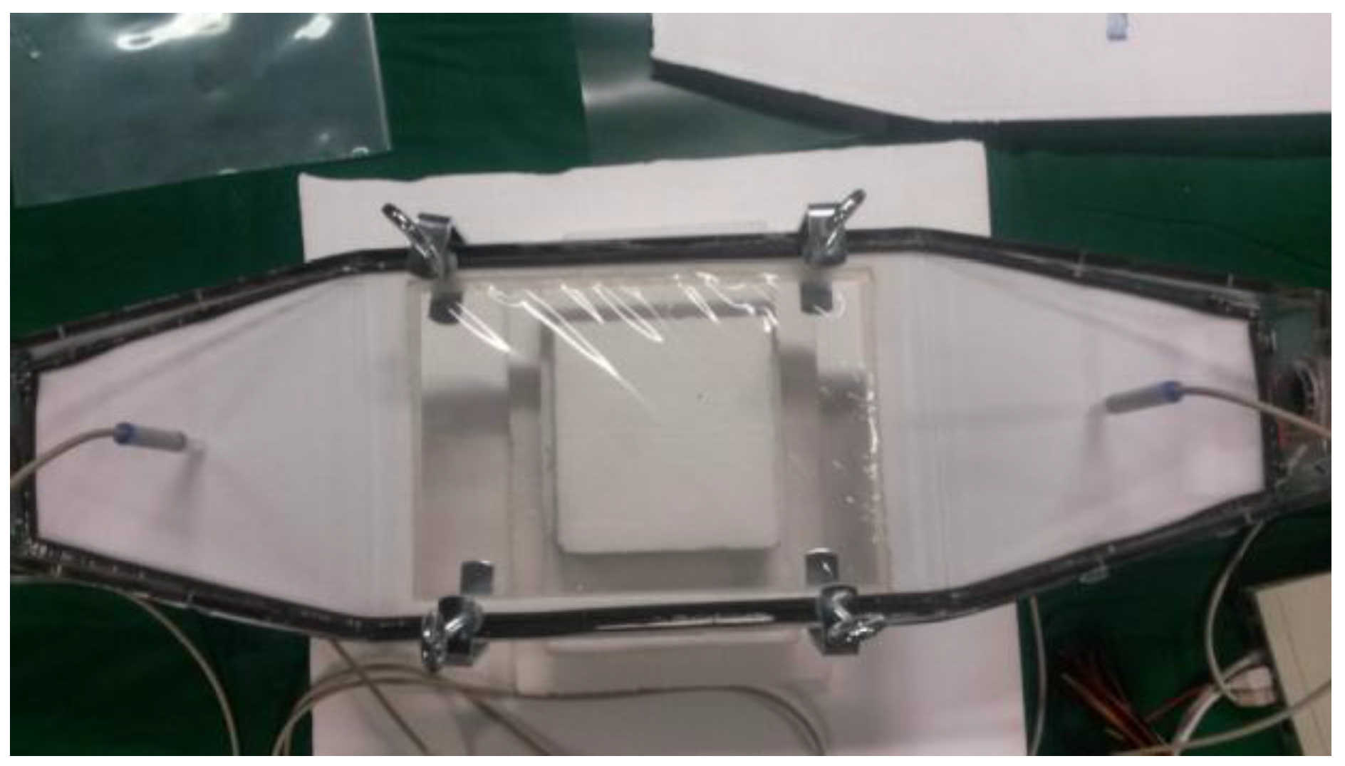
Figure 2.
Support including the membrane for the base unit (plate) of the enthalpy heat exchanger.

Figure 3.
Schematic representation of the enthalpy heat exchanger used for the experimental test.

Figure 4.
Test bench for the performance measurement of the basic unit of the enthalpy heat exchanger. The humidification chamber (a), suction fans (b), exchanger (c).
Figure 4.
Test bench for the performance measurement of the basic unit of the enthalpy heat exchanger. The humidification chamber (a), suction fans (b), exchanger (c).

Figure 5.
Water uptake (WU) vs. time of SPEEK DS 0.70 (90–24).

Figure 6.
Water uptake vs. time for SPEEK DS 0.9 (120–15) in liquid water.

Figure 7.
Equilibrium water uptake coefficients (λ) vs. time for a sample treated at 120–24 and 180–10 with final DS = 0.73, ion exchange capacity (IEC) = 2.1 and crosslinking degree (DXL) = 0.22.
Figure 7.
Equilibrium water uptake coefficients (λ) vs. time for a sample treated at 120–24 and 180–10 with final DS = 0.73, ion exchange capacity (IEC) = 2.1 and crosslinking degree (DXL) = 0.22.
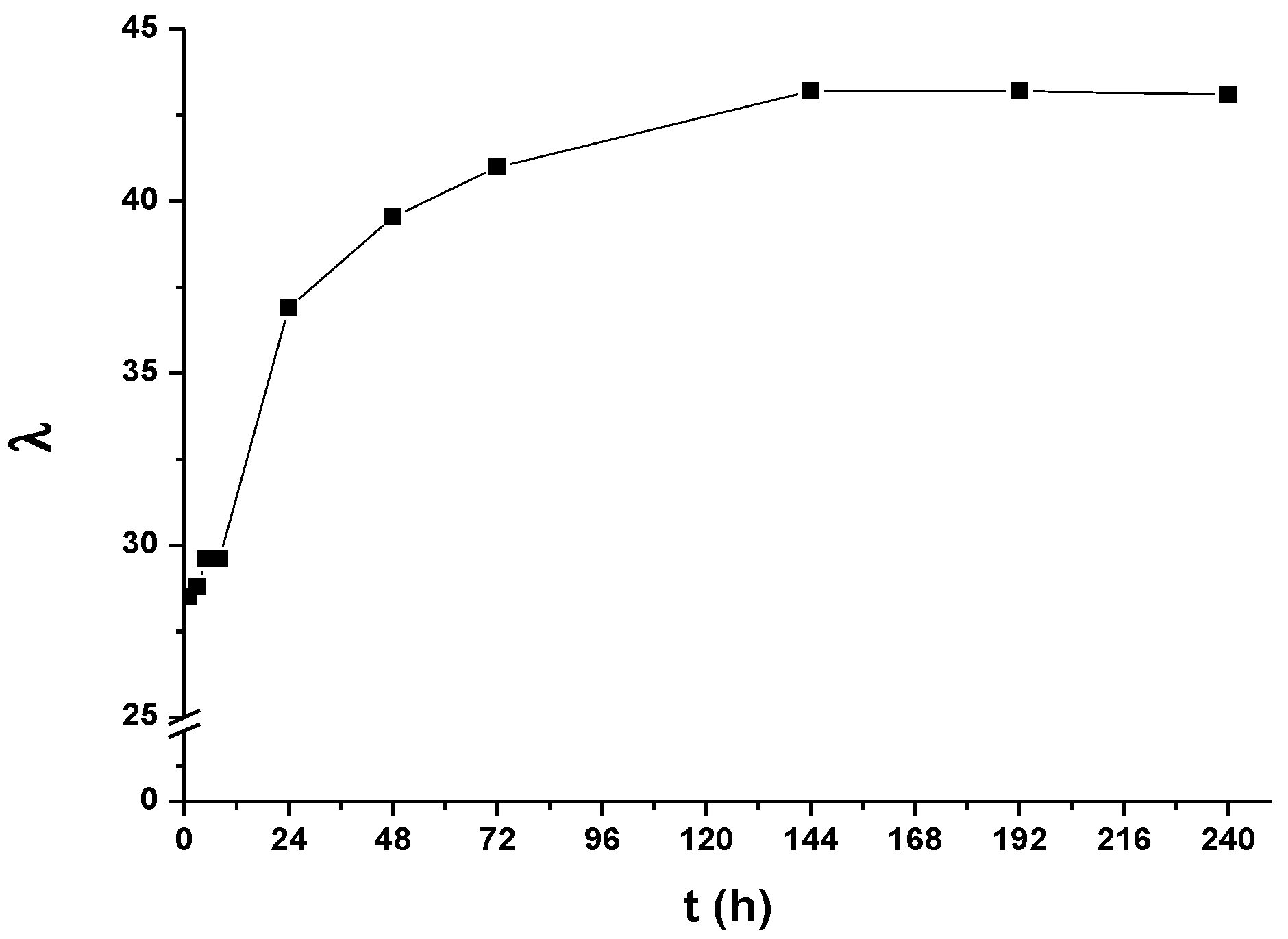
Figure 8.
Plot nc/T of SPEEK in liquid water: SPEEK DS 0.9, blue triangles; SPEEK DS 0.7, green triangles; XL SPEEK DS 0.9 (DXL = 0.1), red triangles.
Figure 8.
Plot nc/T of SPEEK in liquid water: SPEEK DS 0.9, blue triangles; SPEEK DS 0.7, green triangles; XL SPEEK DS 0.9 (DXL = 0.1), red triangles.

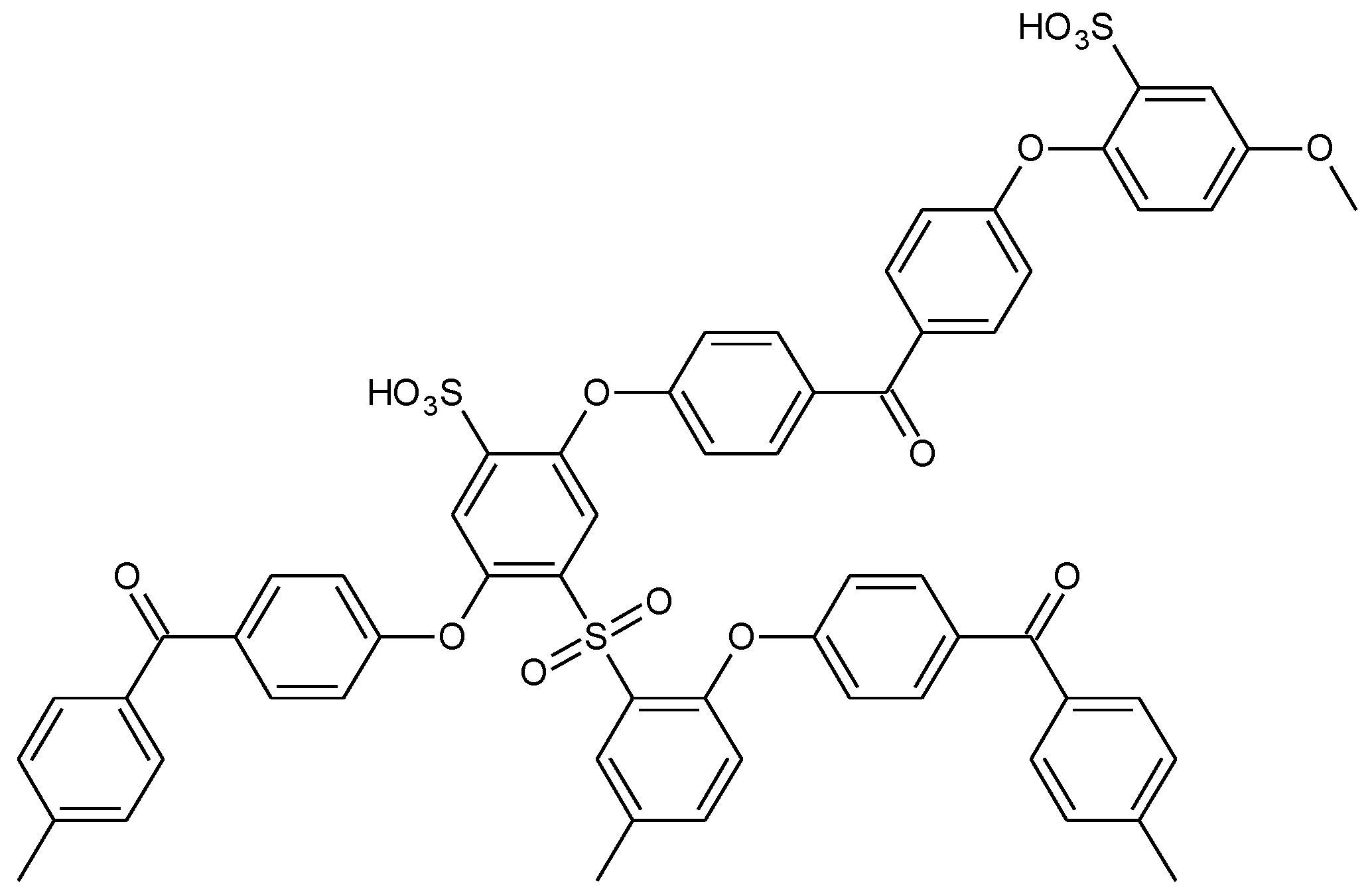
Figure 9.
Repeat unit of SPEEK containing sulfonic groups and sulfone bridges.

Figure 10.
The graph representing the variation of the temperature of the hot stream (green input and red output) and cold flow (gray input and light blue output).
Figure 10.
The graph representing the variation of the temperature of the hot stream (green input and red output) and cold flow (gray input and light blue output).
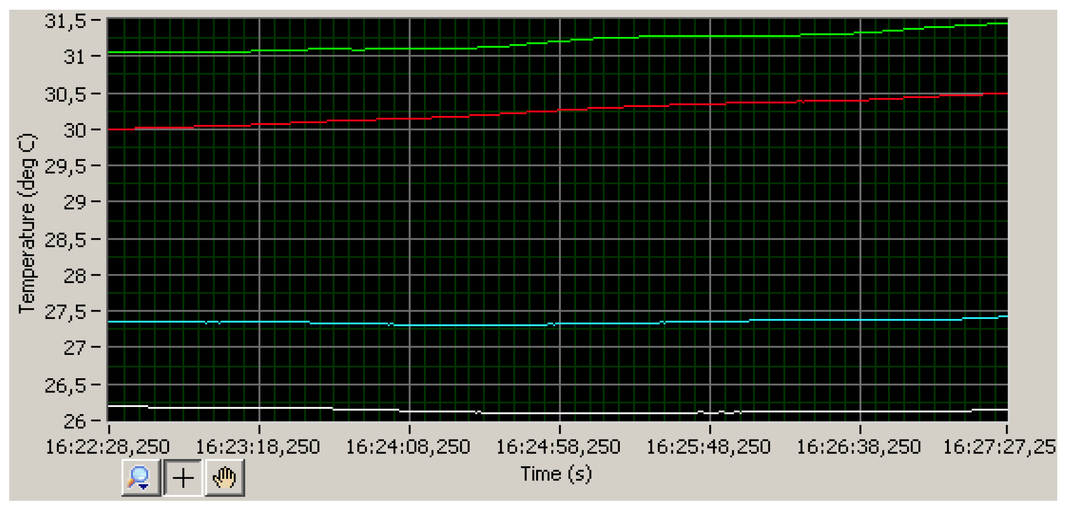
Figure 11.
The graph representing the variation of the relative humidity of the wet stream (entry in red and exit in green) and of the dry stream (entry in light blue and exit in gray).
Figure 11.
The graph representing the variation of the relative humidity of the wet stream (entry in red and exit in green) and of the dry stream (entry in light blue and exit in gray).

Figure 12.
Psychrometric diagram representing the variation of the thermodynamic state of the hot and humid flow in a plastic material.
Figure 12.
Psychrometric diagram representing the variation of the thermodynamic state of the hot and humid flow in a plastic material.

Figure 13.
Psychometric diagram representing the variation of the thermohygrometric state of cold and dry flow in a plastic material.
Figure 13.
Psychometric diagram representing the variation of the thermohygrometric state of cold and dry flow in a plastic material.

Figure 14.
Psychrometric diagram representing the variation of the thermodynamic state of the hot and humid flow in Nafion™ NRE-212.
Figure 14.
Psychrometric diagram representing the variation of the thermodynamic state of the hot and humid flow in Nafion™ NRE-212.

Figure 15.
Psychrometric diagram representing the variation of the thermohygrometric state of the cold and dry flow in Nafion™ NRE-212.
Figure 15.
Psychrometric diagram representing the variation of the thermohygrometric state of the cold and dry flow in Nafion™ NRE-212.
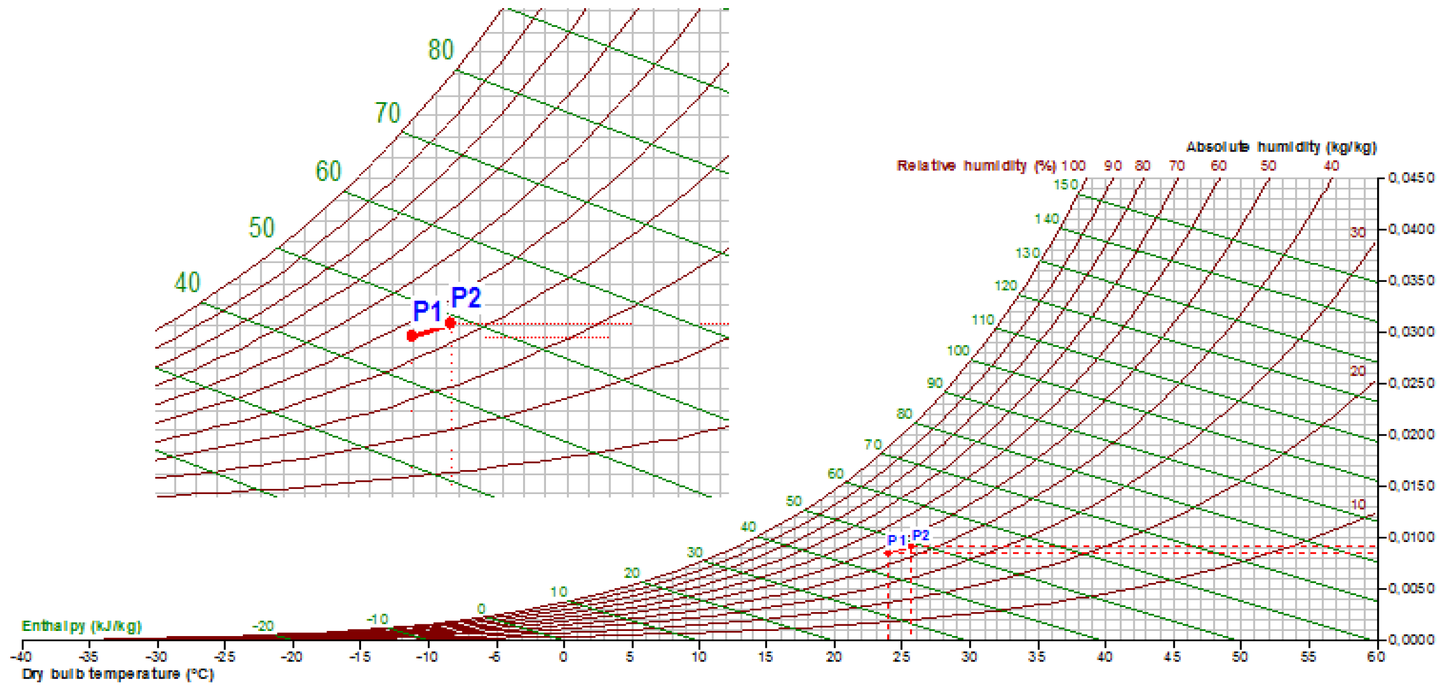
Figure 16.
Psychrometric diagram representing the variation of the thermodynamic state of hot and humid flow in crosslinked SPEEK (DXL = 0.1).
Figure 16.
Psychrometric diagram representing the variation of the thermodynamic state of hot and humid flow in crosslinked SPEEK (DXL = 0.1).

Figure 17.
Psychrometric diagram representing the variation of the thermo-hygrometric state of cold and dry flow in cross-linked SPEEK (DXL = 0.1).
Figure 17.
Psychrometric diagram representing the variation of the thermo-hygrometric state of cold and dry flow in cross-linked SPEEK (DXL = 0.1).


Table 1.
Water uptake (WU), lambda (λ) and counter-elastic pressure (nc) for SPEEK DS 0.7 (90–24) in liquid water at equilibrium.
Table 1.
Water uptake (WU), lambda (λ) and counter-elastic pressure (nc) for SPEEK DS 0.7 (90–24) in liquid water at equilibrium.
| Temperature (°C) | WU (%) H2O 24 h (±5%) | λ H2O 24 h (±5%) | nc H2O 24 h (±5%) |
|---|---|---|---|
| 1.5 | 70 | 20 | 7.1 |
| 5 | 85 | 23 | 5.9 |
| 10 | 107 | 29 | 4.2 |
| 15 | 135 | 32 | 3.8 |
Table 2.
Water uptake (WU), lambda (λ) and counter-elastic pressure (nc) for SPEEK DS 0.9 (120–15) in liquid water at equilibrium.
Table 2.
Water uptake (WU), lambda (λ) and counter-elastic pressure (nc) for SPEEK DS 0.9 (120–15) in liquid water at equilibrium.
| Temperature (°C) | WU (%) H2O 24 h (±5%) | λ H2O 24 h (±5%) | nc H2O 24 h (±5%) |
|---|---|---|---|
| 1 | 50 | 12 | 15.4 |
| 5 | 80 | 20 | 7.1 |
| 10 | 600 | 150 | 0.7 |
Table 3.
Mechanical properties (glass transition temperatures (Tg) [40] for various SPEEK membranes in acid form with an initial IEC= 2.5 meq/g, DS = 0.9 [51] and E: elastic modulus, UTS: ultimate tensile strength, YS: yield stress, ε: elongation at break [52]).
| SPEEK | DXL | E/MPa | UTS/MPa | YS/MPa | ε | Tg/°C |
|---|---|---|---|---|---|---|
| 120 °C, 24 h | 0 | 850 ± 60 | 32 ± 1 | 20 ± 2 | 20 ± 8 | 180 |
| 180 °C, 3 h | 0.1 | 1160 ± 50 | 41 ± 2 | 30 ± 2 | 22 ± 9 | 193 |
| 180 °C, 10 h | 0.22 | 1300 ± 100 | 43 ± 8 | 35 ± 5 | 20 ± 12 | 239 |
| 180 °C, 24 h | 0.35 | 1450 ± 50 | 59 ± 2 | 45 ± 2 | 11 ± 1 | >250 |
Table 4.
Water uptake (WU), lambda (λ), counter-elastic pressure (nc), volume wet (Vwet),= and density wet (dwet) were measured in liquid water for 24 h at 25 °C; volume dry (Vdry) and density dry (ddry) were measured under P2O5 for 24 h for SPEEK (DS = 0.9) and XL SPEEK (DXL = 0.16) [50].
Table 4.
Water uptake (WU), lambda (λ), counter-elastic pressure (nc), volume wet (Vwet),= and density wet (dwet) were measured in liquid water for 24 h at 25 °C; volume dry (Vdry) and density dry (ddry) were measured under P2O5 for 24 h for SPEEK (DS = 0.9) and XL SPEEK (DXL = 0.16) [50].
| Sample | WU (%) (±5%) | λ (±5%) | nc (±5%) | Vwet (mm3) | dwet (g/cm3) | Vdry (mm3) | ddry (g/cm3) (±5%) |
|---|---|---|---|---|---|---|---|
| SPEEK 120–24 (DXL = 0) | ∞ | ∞ | 0 | – | – | 25.4 | 1.35 |
| XL-SPEEK 180–7 H2O 100 °C (DXL = 0.16) | 100 | 25 | 5 | 56.8 | 1.22 | 24.8 | 1.38 |
Table 5.
Environmental humidity (RH) and water uptake (WU) of SPEEK polymer with different degrees of cross-linking (DXL) [53].
Table 5.
Environmental humidity (RH) and water uptake (WU) of SPEEK polymer with different degrees of cross-linking (DXL) [53].
| DXL = 0 | DXL = 0.1 | DXL = 0.22 | |||
|---|---|---|---|---|---|
| RH (±1%) | WU (±5%) | RH (±1%) | WU (±5%) | RH (±1%) | WU (±5%) |
| 15 | 2 | 15 | 2 | 15 | 2 |
| 40 | 8 | 40 | 7 | 40 | 8 |
| 58 | 10 | 58 | 10 | 58 | 12 |
| 80 | 21 | 80 | 18 | 80 | 23 |
| 97 | 46 | 97 | 36 | 97 | 30 |
© 2018 by the authors. Licensee MDPI, Basel, Switzerland. This article is an open access article distributed under the terms and conditions of the Creative Commons Attribution (CC BY) license (http://creativecommons.org/licenses/by/4.0/).
Share and Cite
MDPI and ACS Style
Narducci, R.; Di Vona, M.L.; Marrocchi, A.; Baldinelli, G. Stabilized SPEEK Membranes with a High Degree of Sulfonation for Enthalpy Heat Exchangers. Coatings 2018, 8, 190. https://doi.org/10.3390/coatings8050190
AMA Style
Narducci R, Di Vona ML, Marrocchi A, Baldinelli G. Stabilized SPEEK Membranes with a High Degree of Sulfonation for Enthalpy Heat Exchangers. Coatings. 2018; 8(5):190. https://doi.org/10.3390/coatings8050190
Chicago/Turabian StyleNarducci, Riccardo, Maria Luisa Di Vona, Assunta Marrocchi, and Giorgio Baldinelli. 2018. "Stabilized SPEEK Membranes with a High Degree of Sulfonation for Enthalpy Heat Exchangers" Coatings 8, no. 5: 190. https://doi.org/10.3390/coatings8050190
Note that from the first issue of 2016, this journal uses article numbers instead of page numbers. See further details here.