Article

Effects of Flow Rates and Density Matching on the Integrity of Solid Particles Coated by Water Phase Compound Droplets during the Transport Process

1
School of Chemical Engineering, Sichuan University, Chengdu 610065, China
2
Research Center of Laser Fusion, China Academy of Engineering Physics, Mianyang 621900, China
*
Authors to whom correspondence should be addressed.
Coatings 2018, 8(5), 191; https://doi.org/10.3390/coatings8050191
Submission received: 8 April 2018 / Revised: 5 May 2018 / Accepted: 17 May 2018 / Published: 19 May 2018

Abstract

:
To achieve the integrity of solid particles coated by water phase (S/W/O) compound droplets, it is important to investigate the transport process of the compound droplets in the horizontal straight channel. The experimental results show that the integrity is significantly influenced by the flow rates and density difference. The water (W) phase is observed to be peeled off from the surface of the particles (polystyrene (PS) shells), mainly caused by the slip velocity of the W phase and the density mismatching among three phases. During the peeling off process, a relative motion between the solid (S) and W phases initially occurs, causing a decrease of the distance (δ) between them, and then, the PS shell is driven to pass through the W/O interface under the action of drag force and net gravity. It is also found that increasing flow rates of both phases contributes to obtaining integrated compound droplets. A boundary that separates the integrated from damaged compound droplets also exits when the fluid properties are fixed. Above the line of the boundary, compound droplets with integrity are prepared. Moreover, the absolute optimum density matching between the S and W phases is less than 0.003 g/cm3, while that between the W and oil (O) phases is less than 0.005 g/cm3.

Graphical Abstract

1. Introduction

Solid particles coated by the water phase (S/W/O) are special compound droplets with a solid particle inside. Because the middle phase acts as a coating layer and a carrier that separates the inner solid from the outer fluid, S/W/O compound droplets therefore have a significant potential in a wide range of applications, such as the pharmaceutical industry, bioreactors and inertia confinement fusion (ICF) experiments [1,2,3,4,5,6,7]. Of particular interest is the fabrication of polystyrene shells coated by a polyvinyl alcohol layer (PS-PVA double-layer shells), adopted as a fuel container in ICF experiments [8], which are made up of PS shells, used as the supporting base, and the PVA outer layer serving as a gas-barrier. Besides, the coating of polymethyl methacrylate (PMMA) polymer on a quartz crystal microbalance (QCM) sensor operating in water also shows many applications, such as drag reduction, biological and condensation measurements [9,10,11,12,13]. Generally, such PS-PVA double-layer shells are usually prepared by solidifying the integrated S/W/O compound droplets. However, the conventional stirring method for preparing such compound droplets is ill-controlled, which limits its applications in the fields requiring precise control. As we know, the microfluidic technique provides a promising route for producing W1/O/W2 or O1/W/O2 compound droplets in a precise and controllable manner, but there are a few literature works about the fabrication of S/W/O compound droplets [14,15,16,17,18]. Due to the simple structure, easy facture and low cost, a T-junction device is therefore employed to prepare such compound droplets, in which droplets are formed in the T-junction initially, and then, they are transported through a straight channel. It is important to note that the integrity of compound droplets is always significantly affected by the flow conditions and fluid properties while flowing through a straight channel [19,20]. Flow rates and density matching among three phases are essential parameters to appropriately manipulate compound droplets’ transport in real applications. Therefore, it is of significance to fundamentally investigate the effects of flow conditions and fluid properties on the integrity of the S/W/O compound droplets in a horizontal straight channel.
During the past decade, droplet or bubble transport in a straight channel, involving a two-phase flow, has attracted much interest and can be separated into two categories: bubbly flows for droplets with a diameter smaller than the channel size and slug flows in the opposite case, where each droplet occupies most of the cross-section of the channel. Slug flow is more interesting, from a hydrodynamics point of view, because of the confinement effects. Therefore, researchers had been focused on the investigation of droplet or bubble transport as slug flows, mainly including three aspects: lubrication film, pressure drop along the droplets and the flow field inside the droplets [21,22,23,24,25,26,27,28,29,30,31,32]. Based on droplet transport, Chen et al. investigated the hydrodynamics of a double emulsion droplet in a shear flow and reported four types of breakup modes via three mechanisms (i.e., necking, end pinching and capillary instability), respectively [33]. However, the investigation on the effect of the transport process on the integrity of S/W/O compound droplets is still lacking. The integrated S/W/O compound droplet can only be obtained by reasonably adjusting the flow conditions and fluid properties. Moreover, transportation discrepancies between droplets or double emulsion droplets and S/W/O compound droplets always exist due to the existence of a solid PS shell inside the W phase. The PS shell features the non-deformation of the S/W interface and exhibits a comparatively large diameter to that of the channel in our experiment, leading to a slug-like flow of S/W/O compound droplets’ transportation. Unlike droplets or bubbles, density matching among three phases is a vital physical parameter during the transport of S/W/O compound droplets, because the W phase can be easily peeled off from the surface of a PS shell once it makes contact with the channel wall. Therefore, flow rates and density matching level among three phases are investigated in our experiment.
In this work, the focus is to study the effects of flow rates and density matching among three phases on the integrity of S/W/O compound droplets during the transport process in a horizontal straight channel. The PVA solutions, used as the W phase, were employed to transport the PS shells, whereas dibutyl phthalate (DBP) was used as the O phase to carry the S/W/O compound droplets. A high-speed camera was used to trace the interface evolution. To investigate the effects of density matching among three phases on the integrity of S/W/O compound droplets, the density of the O phase was adjusted by adding dioctyl sebacate (DOS) with different volume fractions, and that of the PS shell was controlled by replacing the inner water with anhydrous calcium chloride (CaCl2) solutions with different mass fractions.

2. Materials and Methods

2.1. Materials

Polydimethylsiloxane (PDMS) (Suzhou Wenhao Lab-on-a-chip Technology Co. Ltd., Suzhou, China), PS ( M ¯ W = 250 kg·mol−1, ρs = 1.05 g·mol−1, Acros Organics Inc., Shanghai, China), high molecular weight (H)-PVA ( M ¯ W = 146–186 kg·mol−1, 99% hydrolysis degree, Aldrich Company, Milwaukee, WI, USA), low molecular weight (L)-PVA ( M ¯ W = 13–23 kg·mol−1, 87%–89% hydrolysis degree, Aldrich Company, Milwaukee, WI, USA), anhydrous calcium chloride (CaCl2) (Chengdu Kelong Chemical Reagent Factory, Chengdu, China), DBP (Chengdu Kelong Chemical Reagent Factory, Chengdu, China) and DOS (Chengdu Kelong Chemical Reagent Factory, Chengdu, China) were all used as received without further purification. Fluorobenzene (FB) (Shanghai Jingchun Reagent Ltd., Shanghai, China) was purified by distillation. Deionized water was used as the solvent of all aqueous phases.

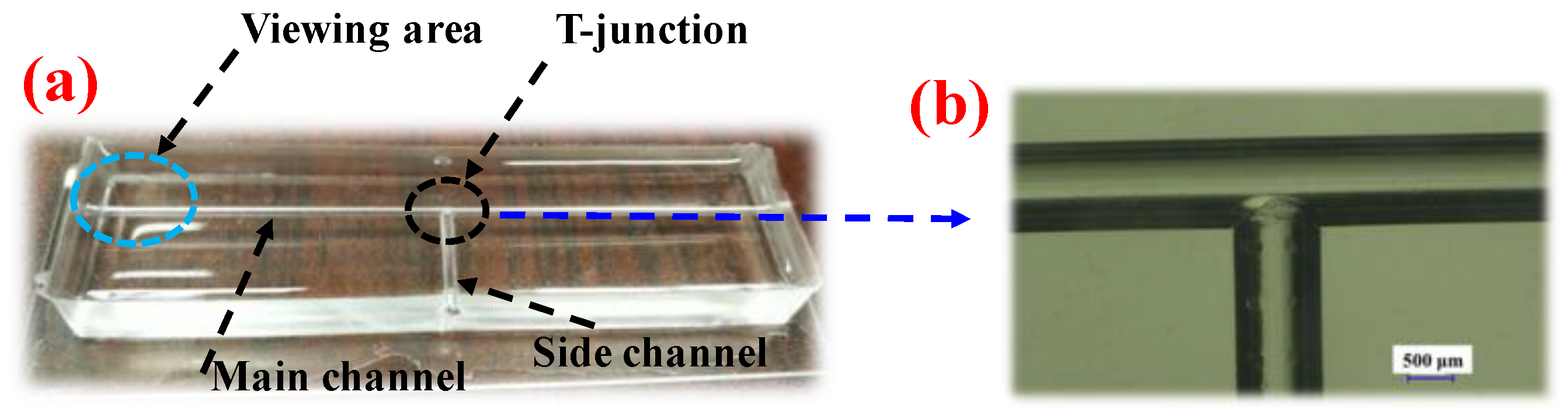
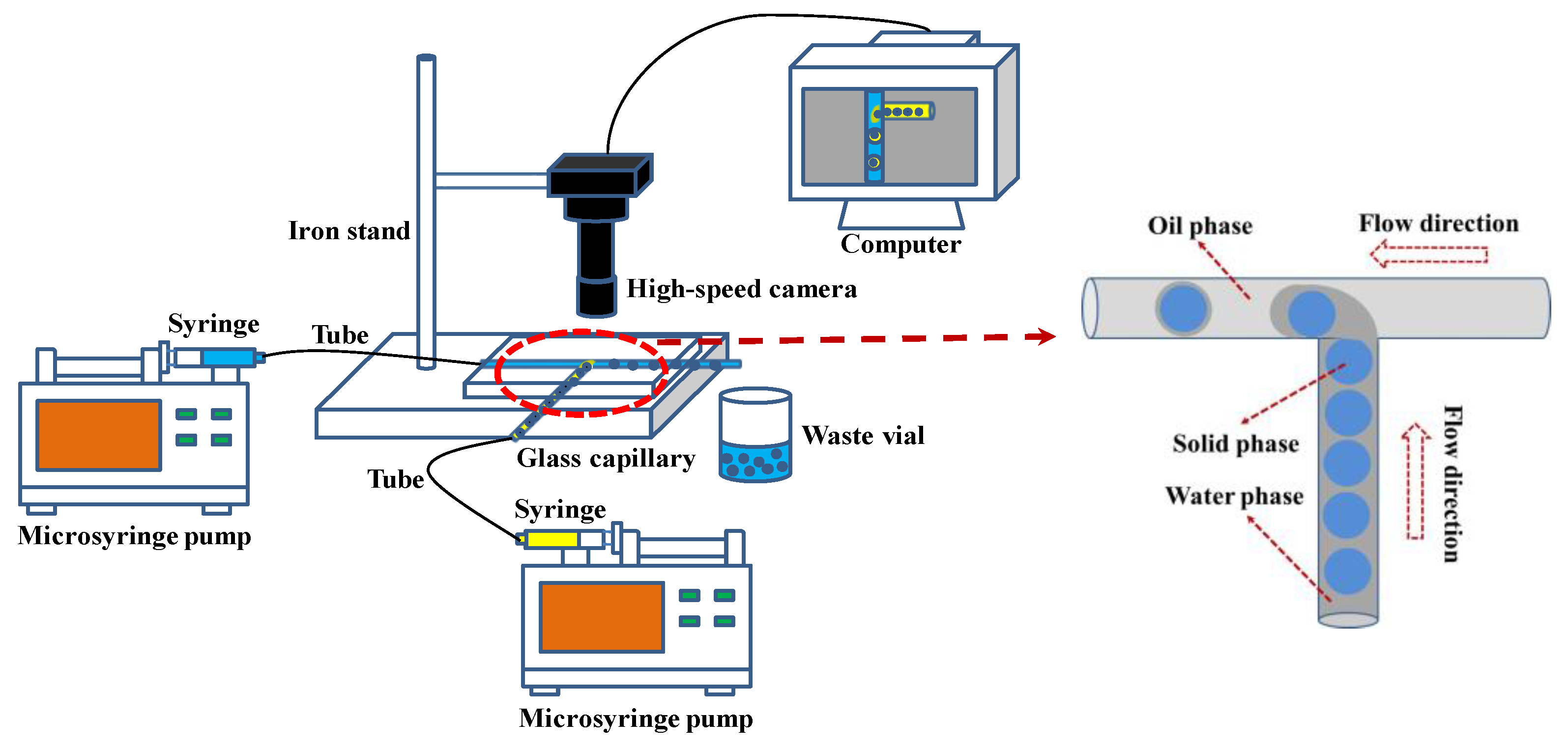
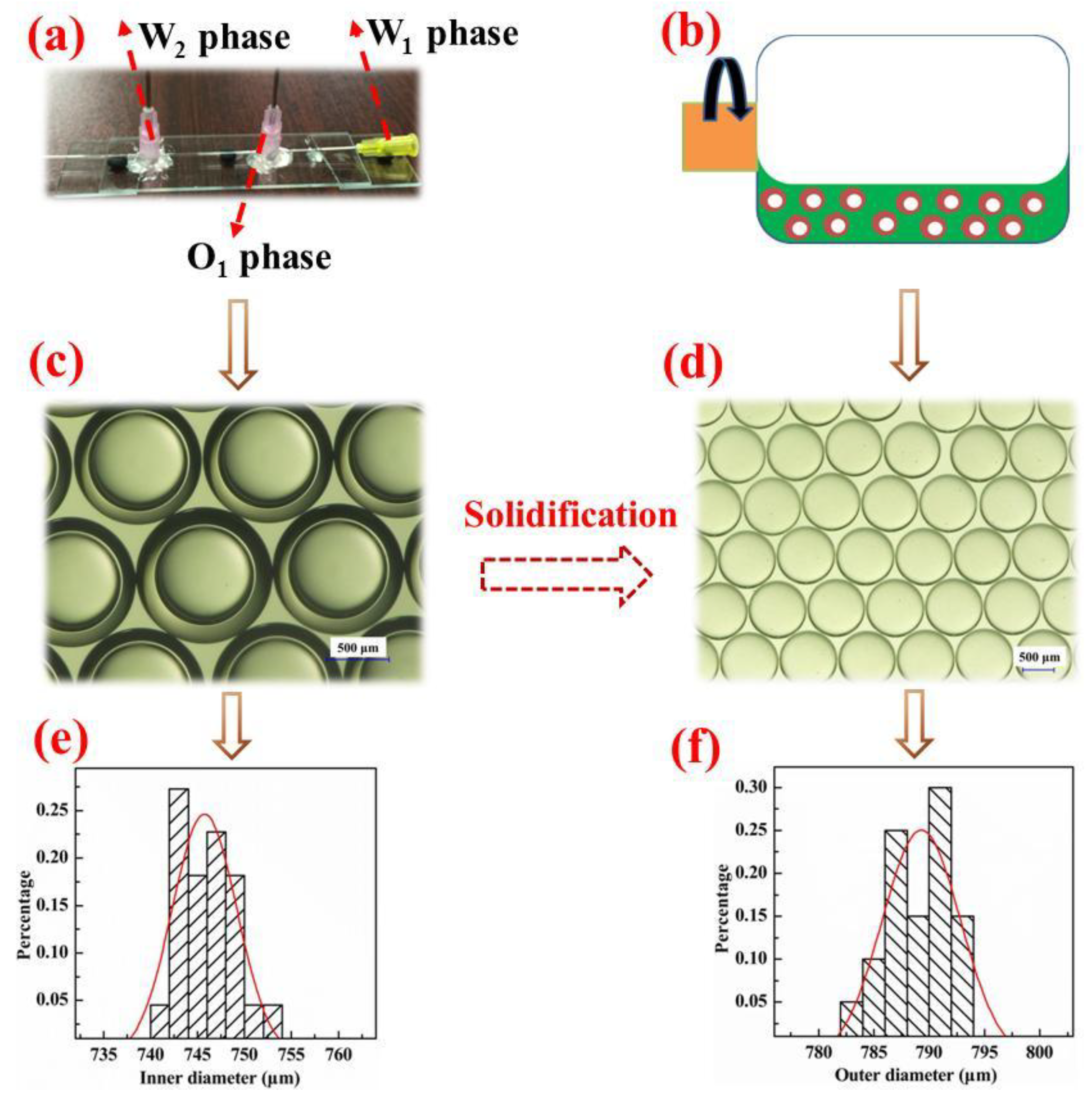
2.2. Experimental Setup and Methods

A 3% H-PVA solution was used to carry the PS shells (the detailed fabrication process is shown in Appendix A.1) through the side channel, whereas the O phase flowed in the main channel. When two immiscible fluids met at the T-junction, the water phase containing PS shells, also called the dispersed phase, was sheared by the continuous phase, by which the S/W/O compound droplets were fabricated. Thereafter, they were released and transported through a straight channel. Two microsyringe pumps were used to control the flow rates of both phases in the microfluidic device. PVA polymer chains can be grafted onto the surface of the PS shell and PDMS channel, which would affect the equivalent diameter of the PS shell and PDMS channel. However, the thickness of the absorption layer was in the range of 20–50 nm, which was thin enough to be neglected compared to the diameters of the PS shell and channel.
S/W/O compound droplets were initially formed in the T-junction (the detailed fabrication of T-junction device is shown in Appendix A.2) and then transported in the straight main channel. A microscope at magnifications from 5–200 was planted on the T-junction device and a high-speed CCD video camera connected to it. The viewing area was approached to the outlet of the main channel (Figure A2a). The recording frequency is 534 frames per second. As shown in Figure 1, the videos of the transport of S/W/O compound droplets were recorded by the computer connected to the video camera. The transport process of S/W/O compound droplets was investigated by analyzing the W/O interface evolution, which was obtained from the recorded images.

3. Results and Discussion

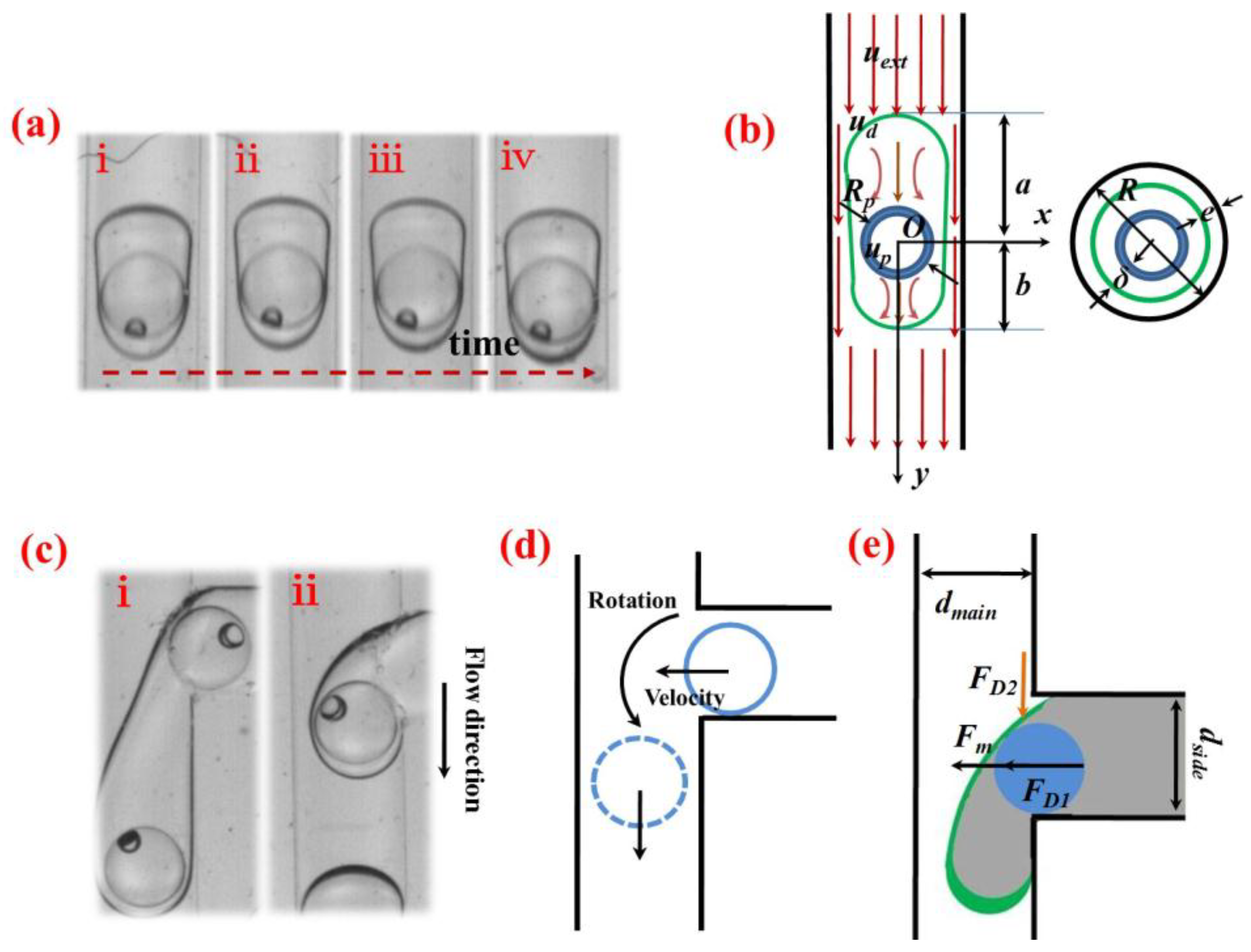
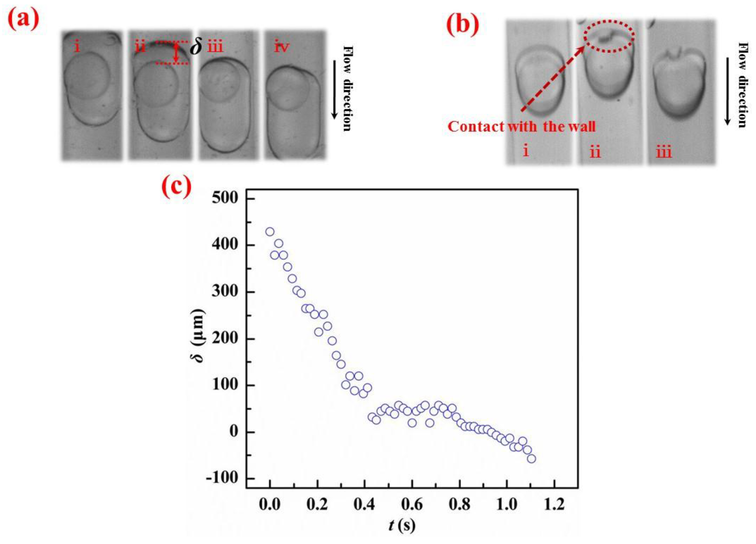
3.1. Analysis of the Transport of S/W/O Compound Droplets

S/W/O compound droplets were initially formed and released at the T-junction, and then, they were transported along the horizontal straight channel by the carrier fluid (O phase). Three formation regimes of S/W/O compound droplets with one solid core inside, which are the squeezing regime, the dripping-like regime and jetting-like regime, can be distinguished by the flow rates in the side and main channels [34]. The schematic sketch of the transport of S/W/O compound droplets in a straight channel is shown in Figure 2b. Bounded by the channel, the transport of S/W/O compound droplets was defined as slug-like flows due to the comparatively large diameter of the PS shell to that of the channel.
When S/W/O compound droplets flowed in a straight channel, the motion of the PS shell was proven to be translation by experiment (Figure 2a), due to the confinement effect by the W phase and the large diameter of the PS shell. Instead, during the formation process of S/W/O compound droplets at the T-junction, the motion of the PS shell, intruding into the main channel from the side channel, was rotation (Figure 2c). The corresponding rotation velocity of it was usually affected by the flow rates in the main and side channels, because the drag force acting on the PS shell varied along with the flow rates. Note that the initial velocity of the PS shell was affected by the rotation velocity. Therefore, when S/W/O compound droplets flowed in a straight channel, the forces that drive the PS shell to move were initial inertia force and drag force, generated by the circular flow field inside the W phase. The equation for drag force, in the condition of Rep < 1, can be expressed as F D = K 6 π μ w R P ( u d u p ) , where K is the revised factor, influenced by the flow field and wall effect, Rp is the radius of the PS shell and ud and up are the velocities of the W phase and PS shell, respectively [35,36]. Accordingly, the motion of a PS shell inside the W phase along the flow direction (y axis) is significantly affected by the flow rates in the main and side channels. Moreover, the motion of PS shell towards the vertical direction is affected by the density difference among the three phases.
As depicted in Figure 3a, the W phase was observed to be peeled off from the surface of the PS shell during the transport process in a straight channel. In the experiment, two different forms of water phase peeling off were observed. One was that the PS shell passed through the W/O interface from the rear of the compound droplets (Figure 3a), while the other was that the W phase was peeled off because of the contact with the channel wall (Figure 3b). In the first case, the velocity of the W phase was always faster than that of the PS shell, resulting in a high flow rate in the main channel, but a relatively low flow rate in the side channel. When the slip velocity of W phase existed, the drag force ( F M ρ w ( u w u p ) 2 A D ) was generated to make the PS shell pass through the W/O interface. Different from the first case, peeling off of the W phase in the second case was mainly caused by the contact with the channel wall. The densities among three phases did not absolutely match in the experiment. PS shell settling along the gravity direction therefore occurred, resulting in a density difference among three phases. When the S/W/O compound droplets advanced a certain distance downstream, the PS shell got close to the channel wall continually. Due to the comparatively large diameter of the PS shell to that of the main channel, the gap distance between the PS shell and the channel wall was always narrow. Accordingly, the PS shell could settle and make contact with the channel wall easily, even at a short advancing distance (Figure 3b). The water phase was peeled off rapidly once the PS shell made contact with the hydrophobic channel wall, resulting in increased friction between the PS shell and the channel wall. Density mismatching was therefore another factor for the peeling off of the W phase. In this case, the force that drove the PS shell to pass through the W/O interface was net gravity. Generally, peeling off of the water phase mainly included two key stages, in which a relative motion between the PS shell and the W phase initially occurred during the transport process, resulting in a thin PVA layer coating on the PS shell, and then, the W phase was peeled off from the surface of the PS shells at the thinnest point of the S/W/O compound droplets. During the relative motion process, the distance (δ) between the PS shell and the water phase decreased with time, as shown in Figure 3c. The velocity difference and density mismatching among the three phases were the two main reasons to impel the relative motion. Drag force and net gravity, resulting in the slip velocity of the W phase and the density difference among the three phases, were the driving forces to make the PS shell pass through the W/O interface.

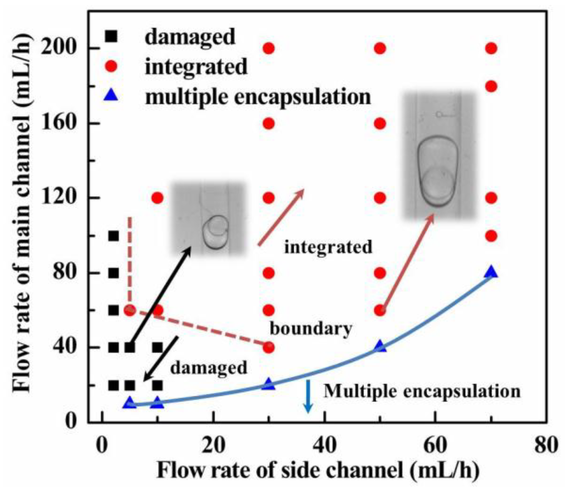
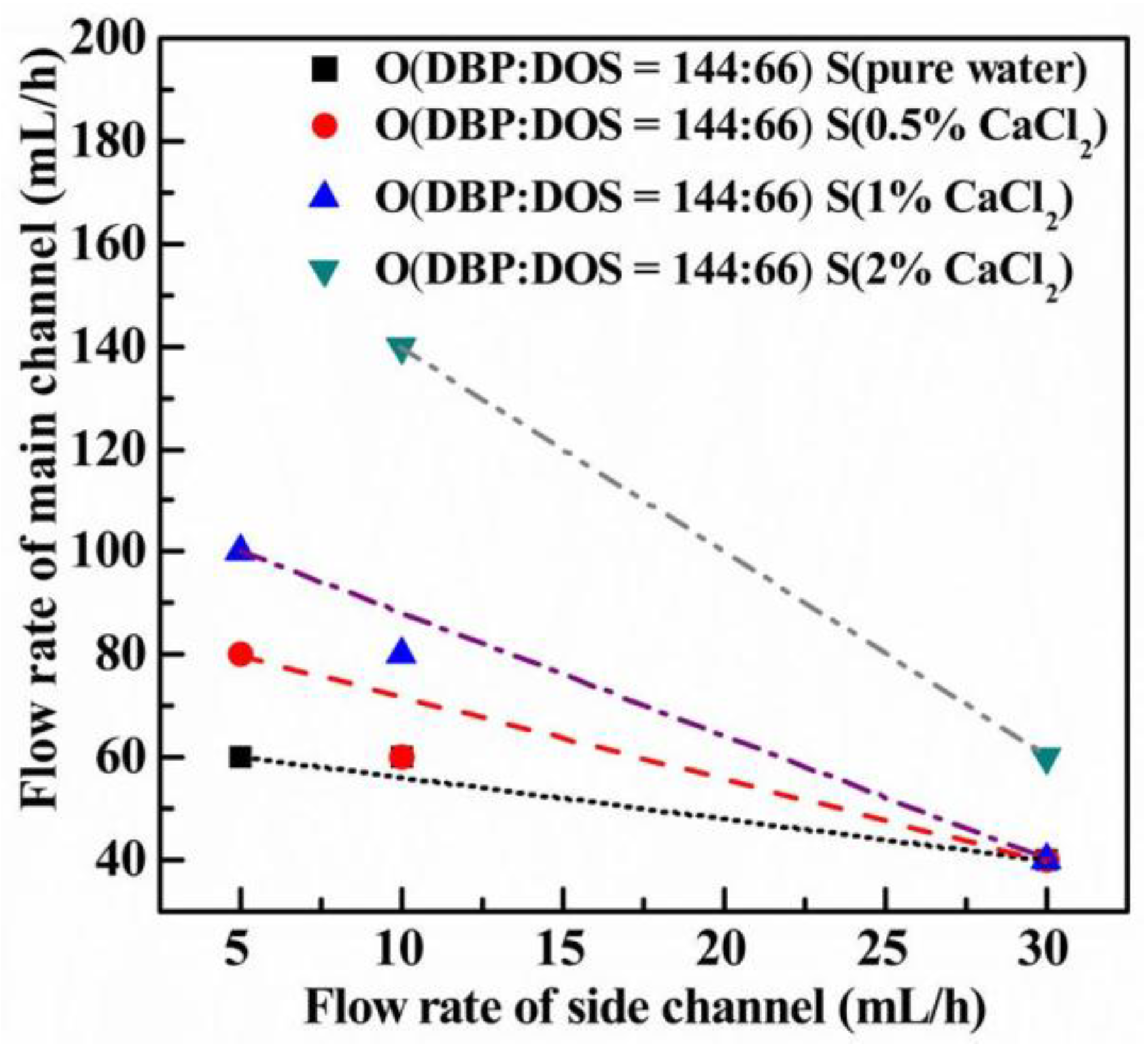
3.2. Effects of Flow Rates on the Integrity of S/W/O Compound Droplets

The transport of S/W/O compound droplets with a single solid core inside was taken into account in the experiment. Damaged S/W/O compound droplets were defined as the W phase being peeled off from the surface of the PS shell, whereas the opposite S/W/O compound droplets were considered as integrated. By observing the motion process of S/W/O compound droplets under a fixed fluid properties, the effects of the flow rates of both phases on the integrity could be investigated. As depicted in Figure 4, both flow rates in the side and main channels had a significant effect on the integrity of S/W/O compound droplets during the transport process. Integrated S/W/O compound droplets can be obtained as the flow rates in the main and side channels increase. Moreover, the boundary that separates the integrated from damaged compound droplets also existed in the figure, which is represented by the red dashed line in Figure 4. In the upper right of the boundary, integrated S/W/O compound droplets could be prepared. Otherwise, damaged compound droplets appeared.
On the one hand, the initial motion velocity of the PS shell inside the S/W/O compound droplets increased as the flow rates in the side and main channels increased during the transport process. As described in Section 3.1, large flow rates in the side and main channels implied that the drag force that made the PS shell rotate in the T-junction increased. Note that the initial velocity of the PS shell was always affected by the rotation velocity. Therefore, the increase of flow rates in the side and main channels could improve the initial velocity of the PS shell. Generally, large initial velocity could eliminate the velocity difference between the PS shell and the W phase. Moreover, with the increase of the flow rate in the main channel, the drag force acting on the W phase significantly increases. Similarly, the shearing force occurring at the W/O interface was also greatly improved. As a result, a fast movement of the W phase resulted in more vortices inside it. Therefore, the drag force acting on the PS shell became large such that it was transported with a higher acceleration. The velocity mismatching between the PS shell and the W phase also could be eliminated by a large flow rate in the main channel. Besides, a higher motion velocity at the transport direction also decreased the settle distance along the gravity direction at the same march distance. This also contributed to obtaining integrated S/W/O compound droplets. In summary, the motion velocity difference could be eliminated by controlling the flow rates in the side and main channels, by which integrated S/W/O compound droplets could be successfully prepared.

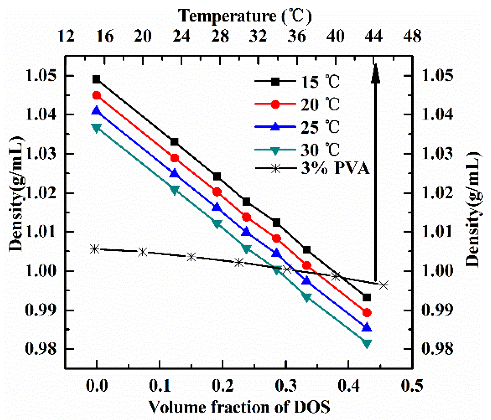
3.3. Effects of Density Matching on the Integrity of S/W/O Compound Droplets

Due to the density difference among three phases, the PS shell and the W phase would move along the gravity direction as they were transported in a straight channel. When the density matching level among three phases and advancing distance along the horizontal direction were fixed, the settlement distance of the PS shell and the water phase along the gravity direction was mainly influenced by the translation velocity, which always depended on the flow rates in the side and main channels. The boundary that separated the integrated from the damaged compound droplets was therefore used to reflect the influences of density matching level on the integrity of S/W/O compound droplets. The effects of the density matching level among three phases on the boundary are shown in Figure 5 and Figure 6. The detailed density matching level data among three phases are shown in Table 1 and Table 2. Besides, the detailed density parameters of oil phase and water phase are shown in Appendix A.3. The boundary shifted to the upper right of the figure with the increasing of the density difference among three phases. This was due to the net gravity, regarded as the only force to drive the PS shell to settle, increasing as the density difference among the three phases increased. To eliminate large density mismatching to obtain the integrated S/W/O compound droplets, the flow rates in the side and main channels should be therefore improved.
Figure 5 and Figure 6 also imply that the integrity of S/W/O compound droplets was more sensitive to the density difference between the S and W phases during the transport process. Under the condition of density matching between the W and O phases, the density difference between the PS shell and the W phase only resulted in the settlement of the PS shell. The position of the W phase kept fixed in the direction of gravity. Therefore, the gap distance between the PS shell and W/O interface sharply decreased. In contrast, the S and W phases, regarded as a whole, together moved along the gravity direction under the condition of density matching between them. The relative motion between the W and S phases reduced. Accordingly, the density difference between the S and W phases can peel off the water phase easily. As depicted in Figure 5 and Figure 6, the black square and red round are almost overlapped. This indicates that the optimum density matching was that the absolute value of the density difference between the W and O phases was less than 0.005 g/cm3 and that between the S and W phases less than 0.003 g/cm3. By adjusting the flow rates in the main and side channels and the density matching level among three phases, integrated S/W/O compound droplets could be obtained, as shown in Appendix A.4.

4. Conclusions

PS/PVA/O compound droplets were prepared by the microfluidic technique via a horizontal T-junction device. Driven by the drag force and net gravity, generated by the slip velocity of the W phase and the density difference among the three phases, the W phase was observed to be peeled off from the surface of the PS shell in the experiment. Both increasing the flow rates of both phases and improving the density matching level together benefitted obtaining integrated S/W/O compound droplets. When the fluid properties of the working system were fixed, a boundary that separated the integrated from the damaged compound droplets existed. Moreover, the optimum absolute value of the density difference between the S and W phases was less than 0.003 g/cm3 and that between the W and O phases less than 0.005 g/cm3. The obtaining of integrated S/W/O compound droplets in a single T-junction device contributes to the preparation of PS-PVA double-layer shells, which satisfy the requirements of ICF experiments.

Author Contributions

D.P. and Q.C. conceived of and designed the experiments. D.P. performed the experiments. D.P. and M.L. analyzed the data. B.L. contributed the high-speed camera to analysis the transport process. D.P. and W.H. wrote the paper.

Funding

This research was funded by National Natural Science Foundation of China (U1530260 and U51703212).

Conflicts of Interest

The authors declare no conflict of interest.

Appendix A

Appendix A.1. Preparation of PS Shells

PS shells were prepared by a “two-step” microencapsulation technique (shown in Figure A1). Details of the fabrication process are in [37,38]. Deionized water was used as the W1 phase. The PS/FB solution with a mass fraction of 8% PS was used as the O1 phase in this work. An aqueous solution with 2% L-PVA ( M ¯ W = 13–23 kg mol−1) and 0.4% CaCl2 was used as the W2 phase.
To limit the possible effects of the diameter and wall thickness of the PS shell on the transport process, the corresponding inner diameter (ID) and outer diameter (OD) of the W1/O1/W2 compound droplets were controlled by adjusting the flow rates of all phases. The ID and wall thickness of the resulting PS shells were maintained in the range of 745 μm ± 10 μm and 22 μm ± 3 μm, respectively. The monodispersity of the inner and outer diameters of PS shells is shown in Figure A1e,f, respectively. Experimental results indicate that the resulting PS shells show a high monodispersity. Therefore, the effects of shell size on the transport process can be ignored in the experiment.
Figure A1. Fabrication of solid particles (PS shell): (a) self-assembled W1/O1/W2 compound droplet generator; (b) curing process of W1/O1/W2 compound droplets; (c) optical images of W1/O1/W2 compound droplets; (d) optical images of PS shells; (e,f) statistics of the monodispersity of the inner and outer diameters of PS shells, respectively.
Coatings 08 00191 g0a1

Appendix A.2. Fabrication of the T-Junction Device

A single T-junction device was fabricated by pouring PDMS into a removable mold, assembled by a glass slide, copper tube, frame, and so on. By disassembling the mold and cutting the unneeded PDMS, high fidelity intact chips with various sizes can be easily prepared. The physical map and optical image of the T-junction device are shown in Figure A2a,b, respectively. The diameters of the main and side channels were 980 μm and 960 μm, respectively. The channels were oriented horizontally in all experiments.
Figure A2. Sketch map of the T-junction device: (a) physical map of the T-junction device; (b) optical image of the T-junction.
Coatings 08 00191 g0a2

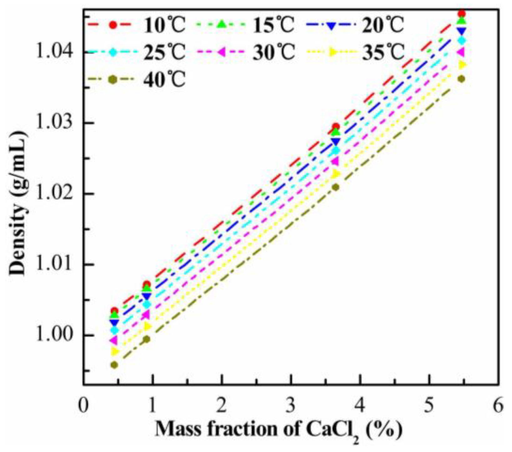
Appendix A.3. Density Matching among Three Phases

The PS shell was used as the solid phase in the experiment, and its apparent density can be calculated by the following expression:
ρ ¯ = ρ w d 1 3 + ρ p ( d 2 3 d 1 3 ) d 2 3
where ρ w is the density of the water phase, ρ p is the density of the PS shell and d1 and d2 are the inner and outer diameters of the PS shell, respectively. To investigate the influences of density matching between S/W/O compound droplets and the O phase, O phases with various volume fractions of DOS in the DBP were employed to match the same S/W/O compound droplets. To exclude the possible effects of the density difference between S and W phases, 3% PVA solutions were selected to match the PS shell with the inner water drop (ID ~ 745 μm, OD ~ 790 μm). The density curve of 3% PVA solutions versus the temperature and the density of the O phases with various volume fractions of DOS are shown together in Figure A3. Three different O phases (DBP:DOS = 144:66, DBP:DOS = 150:60, DBP:DOS = 160:50) were used to investigate the effects of density matching between compound droplets and the O phase on the transport of such compound droplets. The density matching during the transport process not only involves the density matching between the compound droplets and O phase, but also includes that between the S and W phases. To further examine the influences of the density matching between the PS shell and the W phase on the integrity of S/W/O compound droplets, PS shells with different densities were used to match the 3 wt.% PVA solutions. To ensure the density matching between the W and O phases, the O phase with a specific volume fraction (DBP:DOS = 144:66) was employed. To obtain PS shells with various densities, the inner diameter and wall thickness of the PS shell were kept constant, whereas the inner water was replaced by the CaCl2 solutions. The curve of the density with different mass fractions of CaCl2 solutions inside the PS shells is shown in Figure A4. The densities of PS shells with different mass fractions of CaCl2 can be therefore calculated with Equation (A1) and Figure A4.
Figure A3. Curve of the density of 3 wt.% PVA solutions at different temperatures and the density of DBP with various volume fractions.
Coatings 08 00191 g0a3
Figure A4. Density of CaCl2 solutions with different mass fractions.
Coatings 08 00191 g0a4

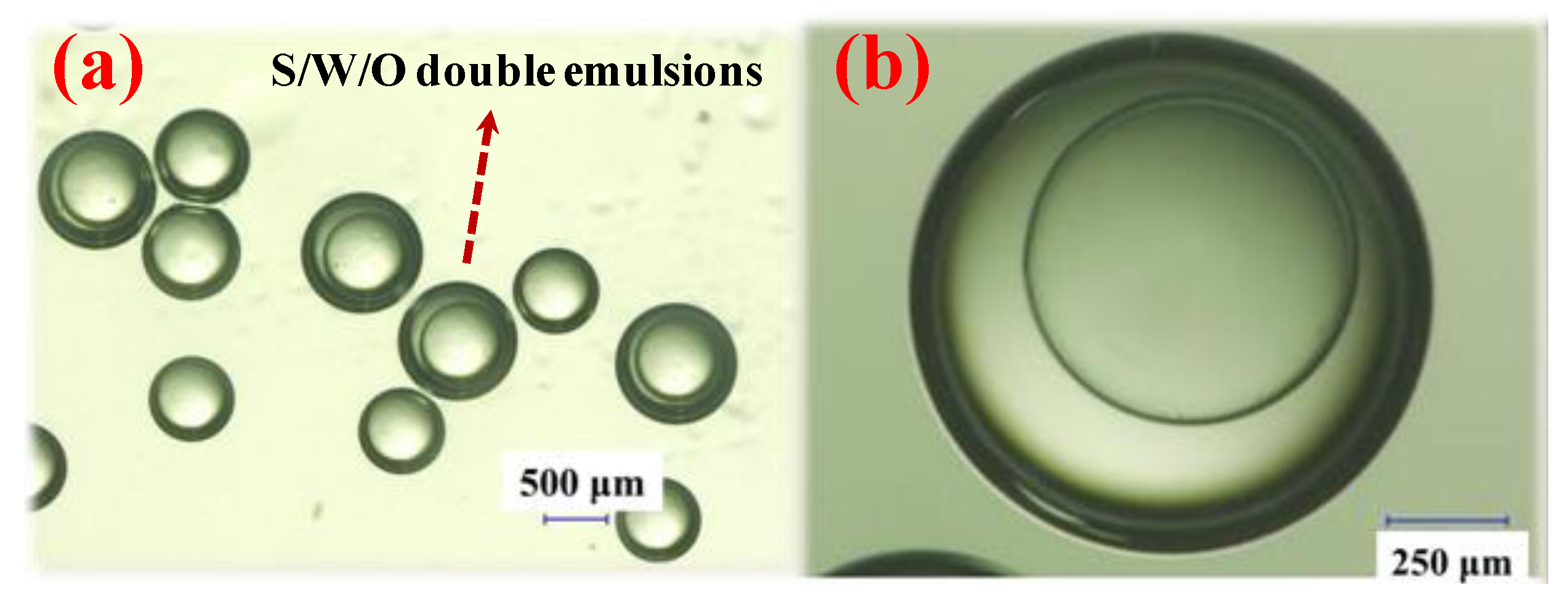
Appendix A.4. Optical Images of S/W/O Compound Droplets

By adjusting the flow rates in the main and side channels and the density matching level among three phases, integrated S/W/O compound droplets could be obtained, as shown in Figure A5a,b.
Figure A5. Optical images of integrated S/W/O compound droplets.
Coatings 08 00191 g0a5

References

  1. Sefton, M.V.; May, M.H.; Lahooti, S.; Babensee, J.E. Making microencapsulation work: Conformal coating, immobilization gels and in vivo performance. J. Controll. Release 2000, 65, 173–186. [Google Scholar] [CrossRef]
  2. Khademhosseini, A.; May, M.H.; Sefton, M.V. Conformal coating of mammalian cells immobilized onto magnetically driven beads. Tissue Eng. 2005, 11, 1797–1809. [Google Scholar] [CrossRef] [PubMed]
  3. Taly, V.; Kelly, B.T.; Griffiths, A.D. Droplets as microreactors for high-throughput biology. ChemBioChem 2007, 8, 263–272. [Google Scholar] [CrossRef] [PubMed]
  4. Shum, H.C.; Bandyopadhyay, A.; Bose, S.; Weitz, D.A. Double emulsion droplets as microreactors for synthesis of mesoporous hydroxyapatite. Chem. Mater. 2009, 21, 5548–5555. [Google Scholar] [CrossRef]
  5. Norimatsu, T.; Nagai, K.; Yamanaka, T.; Endo, T.; Yoshida, H.; Sakagami, Y. Activities on target fabrication and injection toward laser fusion energy in Japan. Fusion Eng. Des. 2002, 63–64, 587–596. [Google Scholar] [CrossRef]
  6. Letts, S.A.; Fearon, E.M.; Buckley, S.R.; Saculla, M.D.; Allison, L.M.; Cook, R. Fabrication of polymer shells using a depolymerizable mandrel. Fusion. Sci. Technol. 1995, 28, 1797–1802. [Google Scholar] [CrossRef]
  7. Norimatsu, T.; Takagi, M.; Takaki, T.; Morimoto, K.; Izawa, Y.; Mima, K. Recent research on target fabrication for up-coming projects. Fusion Eng. Des. 1999, 44, 449–459. [Google Scholar] [CrossRef]
  8. Alan, K.B.; John, Z.G.; Eben, M. Fabrication of Polyvinyl alcohol coated polystyrene shells. J. Vac. Sci. Technol. A 1987, 6, 3417–3421. [Google Scholar]
  9. Esmaeilzadeh, H.; Zheng, K.; Su, J.; Mead, J.; Sobkowicz, M.J.; Sun, H. Experimental study of drag reduction on superhydrophobic surfaces using quartz crystal microbalance. In Proceedings of the ASME International Mechanical Engineering Congress and Exposition, Tampa, FL, USA, 3–9 November 2017. [Google Scholar]
  10. Su, J.; Esmaeilzadeh, H.; Zhang, F.; Yu, Q.; Cernigliaro, G.; Xu, J.; Sun, H. An ultrasensitive micropillar-based quartz crystal microbalance device for real-time measurement of protein immobilization and protein-protein interaction. Biosens. Bioelectron. 2018, 99, 325–331. [Google Scholar] [CrossRef] [PubMed]
  11. Esmaeilzadeh, H.; Cernigliaro, G.; Su, J.; Gong, L.; Mirzaee, I.; Charmchi, M.; Sun, H. The effects of material properties on pillar-based QCM sensors. In Proceedings of the ASME International Mechanical Engineering Congress and Exposition, Houston, TX, USA, 13–19 November 2015. [Google Scholar]
  12. Su, J.; Esmaeilzadeh, H.; Sun, H. Study of frequency response of quartz crystal microbalance to different wetting states of micropillar surfaces. In Proceedings of the ASME Fluids Engineering Division Summer Meeting, Waikoloa, HI, USA, 30 July–3 August 2017. [Google Scholar]
  13. Su, J.; Inalpolat, M.; Ge, T.; Esmaeilzadeh, H.; Sun, H. Experimental study and analysis of dropwise condensation using quartz crystal microbalance. In Proceedings of the ASME Heat Transfer Summer Conference, Washington, DC, USA, 10–14 July 2016. [Google Scholar]
  14. Thorsen, T. Dynamic pattern formation in a vesicle-generation microfluidic device. Phys. Rev. Lett. 2001, 86, 4163–4166. [Google Scholar] [CrossRef] [PubMed]
  15. Srinivasan, V.; Pamula, V.K.; Fair, R.B. An integrated digital microfluidic lab-on-a-chip for clinical diagnostics on human physiological fluids. Lab Chip. 2004, 4, 310–315. [Google Scholar] [CrossRef] [PubMed]
  16. Li, X.B.; Li, F.C.; Yang, J.C.; Kinoshita, H.; Oishi, M.; Oshima, M. Study on the mechanism of droplet formation in T-junction microchannel. Chem. Eng. Sci. 2012, 69, 340–351. [Google Scholar] [CrossRef]
  17. De Menech, M.; Garstecki, P.; Jousse, F.; Stone, H.A. Transition from squeezing to dripping in a microfluidic T-shaped junction. J. Fluid Mech. 2008, 595, 141–161. [Google Scholar] [CrossRef]
  18. Garstecki, P.; Fuerstman, M.J.; Stone, H.A.; Whitesides, G.M. Formation of droplets and bubbles in a microfluidic T-junction-scaling and mechanism of breakup. Lab Chip. 2006, 6, 437–446. [Google Scholar] [CrossRef] [PubMed]
  19. Engl, W.; Roche, M.; Colin, A.; Panizza, P. Droplet traffic at a simple junction at low capillary number. Phys. Rev. Lett. 2005, 95, 208304. [Google Scholar] [CrossRef] [PubMed]
  20. Song, H.; Tice, J.D.; Ismagilov, R. A microfluidic system for controlling reaction networks in time. Angew. Chem. Int. Ed. 2003, 42, 768–772. [Google Scholar] [CrossRef] [PubMed]
  21. Bretherton, F.P. The motion of long bubbles in tubes. J. Fluid Mech. 1961, 10, 166–188. [Google Scholar] [CrossRef]
  22. Ratulowski, J.; Chang, H.C. Transport of gas bubbles in capillaries. Phys. Fluids 1989, 1, 1642–1655. [Google Scholar] [CrossRef]
  23. Hodges, S.R.; Jensen, O.E.; Rallison, J.M. The motion of a viscous drop through a cylindrical tube. J. Fluid Mech. 2004, 501, 279–301. [Google Scholar] [CrossRef]
  24. Schwartz, L.W.; Princen, H.M.; Kiss, A.D. On the motion of bubbles in capillary tubes. J. Fluid Mech. 1986, 172, 259–275. [Google Scholar] [CrossRef]
  25. Reinelt, D.A.; Saffman, P.G. The penetration of a finger into a viscous fluid in a channel and tube. SIAM. J. Sci. Comput. 1985, 6, 542–561. [Google Scholar] [CrossRef]
  26. Hazel, A.L.; Heil, M. The steady propagation of a semi-infinite bubble into a tube of elliptical or rectangular cross-section. J. Fluid Mech. 2002, 470, 91–114. [Google Scholar] [CrossRef]
  27. Adzima, B.J.; Velankar, S.S. Pressure drop for droplets flows in microfluidic channels. J. Micromech. Microeng. 2006, 16, 1504–1510. [Google Scholar] [CrossRef]
  28. Jousse, F.; Lian, G.P.; Janes, R.; Melrose, J. Compact model for multi-phase liquid–liquid flows in micro-fluidic devices. Lab Chip. 2005, 5, 646–656. [Google Scholar] [CrossRef] [PubMed]
  29. Fuerstman, M.J.; Lai, A.; Thurlow, M.E.; Shevkoplyas, S.S.; Stone, H.A.; Whitesides, G.M. The pressure drop along rectangular microchannels containing bubbles. Lab Chip. 2007, 7, 1479–1489. [Google Scholar] [CrossRef] [PubMed]
  30. Sarrazin, F.; Prat, L.; Miceli, N.D.; Cristobal, G.; Link, D.R.; Weitz, D.A. Mixing characterization inside microdroplets engineered on a microcoalescer. Chem. Eng. Sci. 2007, 62, 1042–1048. [Google Scholar] [CrossRef] [Green Version]
  31. Kinoshita, H.; Kaneda, S.; Fujii, T.; Oshima, M. Three dimensional measurement and visualization of internal flow of a moving droplet using confocal micro-PIV. Lab Chip. 2007, 7, 338–346. [Google Scholar] [CrossRef] [PubMed]
  32. Lindken, R.; Rossi, M.; Westerweel, J. Micro-particle image velocimetry (mPIV): Recent developments, applications, and guidelines. Lab Chip. 2009, 9, 2551–2567. [Google Scholar] [CrossRef] [PubMed]
  33. Chen, Y.P.; Liu, X.D.; Shi, M.H. Hydrodynamics of double emulsion droplet in shear flow. Appl. Phys. Lett. 2013, 102, 051609. [Google Scholar] [CrossRef]
  34. Pan, D.W.; Liu, M.F.; Li, F.; Chen, Q.; Liu, X.D.; Liu, Y.Y.; Zhang, Z.W.; Huang, W.X.; Li, B. Formation mechanisms of solid in water in oil compound droplets in a horizontal T-junction device. Chem. Eng. Sci. 2018, 176, 254–263. [Google Scholar] [CrossRef]
  35. Staben, M.E.; Galvin, K.P.; Davis, R.H. Low-Reynolds-number motion of a heavy sphere between the two parallel plane walls. Chem. Eng. Sci. 2006, 61, 1932–1945. [Google Scholar] [CrossRef]
  36. Staben, M.E.; Davis, R.H. Particle transport in Poiseuille flow in narrow channels. Int. J. Multiph. Flow. 2005, 31, 529–547. [Google Scholar] [CrossRef]
  37. Liu, M.F.; Chen, S.F.; Qi, X.B.; Li, B.; Shi, R.T.; Liu, Y.Y.; Chen, Y.P.; Zhang, Z.W. Improvement of wall thickness uniformity of thick-walled polystyrene shells by density matching. Chem. Eng. J. 2014, 241, 466–476. [Google Scholar] [CrossRef]
  38. Shao, T.; Feng, X.; Jin, Y.; Cheng, Y. Controlled production of compound droplets in dual-coaxial capillaries device for millimeter-scale hollow polymer spheres. Chem. Eng. Sci. 2013, 104, 55–63. [Google Scholar] [CrossRef]
Figure 1. Schematic of the experimental setup for tracking the interface evolution.
Coatings 08 00191 g001
Figure 2. Motion behaviors of the polystyrene (PS) shell in a straight channel and a T-junction: (a) PS shell motion with translation; (b) schematic sketch of the transport of S/W/O compound droplets in a straight channel; (c) motion of the PS shell with rotation in the T-junction by experiment; (d) schematic motion of the PS shell with rotation in the T-junction; (e) correlative forces acting on the PS shell in the T-junction.
Coatings 08 00191 g002
Figure 3. Phenomenon of the W phase peeled off from the surface of the PS shell: (a) the velocity of the PS shell was lower than that of the W phase; (b) contact with the bottom wall of the channel; (c) the distance (δ) between the PS shell and the W phase at different times during the relative motion.
Coatings 08 00191 g003
Figure 4. Effects of flow rates on the integrity of S/W/O compound droplets.
Coatings 08 00191 g004
Figure 5. Effects of the density difference between the O and W phases on the boundary that separates the integrated from the damaged compound droplets.
Coatings 08 00191 g005
Figure 6. Effects of the density difference between the S and W phases on the boundary that separates the integrated from the damaged compound droplets.
Coatings 08 00191 g006
Table 1. Density matching level between the O phase and S/W/O compound droplets. DBP, dibutyl phthalate; DOS, dioctyl sebacate.
O PhaseW PhaseS PhaseΔρO-W (g/cm3)ΔρS-W (g/cm3)
DBP:DOS = 144:663% PVAPure water0.000240.00024
DBP:DOS = 150:603% PVAPure water0.005320.00024
DBP:DOS = 170:403% PVAPure water0.017180.00024
DBP3% PVAPure water0.041980.00024
Table 2. Density matching level between the S and W phases.
O PhaseW PhaseS PhaseΔρO-W (g/cm3)ΔρS-W (g/cm3)
DBP:DOS = 144:663% PVAPure water0.0002430.00024
DBP:DOS = 144:663% PVA0.5% CaCl20.0002430.00366
DBP:DOS = 144:663% PVA1.0% CaCl20.0002430.004838
DBP:DOS = 144:663% PVA2.0% CaCl20.0002430.011905

