Oxidation Behavior of MoSi2-Coated TZM Alloys during Isothermal Exposure at High Temperatures
by
 ,
,
Kwangsu Choi
1 ,
,
Young Joo Kim
1,
Min Kyu Kim
1,
Sangyeob Lee
1,
Seong Lee
2 and
Joon Sik Park
1,* 1
Department of Materials Science and Engineering, Hanbat National University, Daejeon 34158, Korea
2
Agency for Defense System, Yuseong P.O. Box 35-5, Daejeon 34060, Korea
*
Author to whom correspondence should be addressed.
Coatings 2018, 8(6), 218; https://doi.org/10.3390/coatings8060218
Submission received: 15 May 2018
/
Revised: 7 June 2018
/
Accepted: 8 June 2018
/
Published: 11 June 2018
(This article belongs to the Special Issue Coatings for Harsh Environments)
Abstract
:Coating properties and oxidation behaviors of Si pack cementation-coated TZM (Mo-0.5Ti-0.1Zr-0.02C) alloys were investigated in order to understand the stability of the coating layer at high temperatures up to 1350 °C in an ambient atmosphere. After the pack cementation coatings, MoSi2 and Mo5Si3 layers were formed. When MoSi2-coated TZM alloys were oxidized in air at high temperatures, the Si in the outer MoSi2 layer diffused and formed SiO2. Also, due to the diffusion of Si, the MoSi2 layer was transformed into a columnar shaped Mo5Si3 phase. During isothermal oxidation, the Mo5Si3 phase was formed both within the coated MoSi2 layer and between the MoSi2 and the substrate. The coating properties and the oxidation behavior of the Si pack-coated TZM alloys were discussed along with the identification of growth kinetics.
1. Introduction
TZM alloys are traditional Mo-based alloys that are typically used for high temperature applications due to their superior material properties at high temperatures. The phase constituting TZM alloys are composed of mainly Mo matrix with precipitates of TiC and/or ZrC. Detailed material properties have been reported elsewhere [1,2,3,4,5]. In particular, since the alloys are stable with liquid state metals, they have been applied in high temperature components such as atomic plant components. However, since the alloys are mainly composed of Mo, the low stability of Mo during high temperature exposure under an ambient atmosphere is a serious limitation of these alloys. Specifically, when the alloys are exposed in air at high temperatures above 400 °C, a volatile and non-protective Mo oxide, MoO3, is formed. This ruins the usefulness of the alloys due to the nature of the non-protective oxidation behaviors of Mo [6,7].
Mo-based alloys have been studied in the past to improve oxidation resistance through surface coatings. Surface protection coatings such as thermal plasma spray, sputtering coatings, or pack cementation coatings have been studied in order to improve oxidation resistance at the exposure to high temperatures under an ambient atmosphere [8,9,10,11]. Among the coating routes, the pack cementation coating process has the capability of producing a uniform coating layer on complex shaped substrates, and is effective in preventing oxygen penetration [2,4,7,12,13,14,15,16,17]. According to the literature, the formation of protective coating layers can be achieved by Si or Al pack cementation coatings [2,4,11]. Upon the application of Si pack cementation coatings on the alloy, MoSi2 phase, a highly oxidation resistant material, is formed as a result of the diffusion of Si into Mo in the matrix. When the MoSi2 phase is exposed in air at high temperatures, SiO2 is formed on the surface of the MoSi2 layer, implying that the coated TZM alloys exhibit excellent oxidation resistant behaviors [1]. Furthermore, the effectiveness of Al-Si silicide coatings has been reported. The coating layers composed of Mo(Si, Al)2 can provide protection to the TZM alloys through the formation of an Al2O3 layer on the surface [7]. Besides these, systematic reports have also been published which focus on the formation of pack cementation coating layers with various compositions and coating kinetics using different halide activators [7].
In order to apply the coated TZM alloys on structural parts that require reproducible credibility, such as defense systems, the coating layers should have properties such as (i) strong bonding with the substrate; (ii) a defect-free coating layer in complex-shaped structures; and (iii) a defined lifetime of the coating layer with respect to exposure at high temperatures. While the nature of the pack cementation coating process suitably matches with the aforementioned two requirements, the lifetime kinetics of MoSi2-coated TZM alloys have not been systematically investigated at high temperatures during oxidation exposure. In reality, the lifetime analyses of the coating layers are a critical issue for the practical application of the coated TZM alloys, such as structural parts for defense systems, in order to provide reproducible service time and temperatures.
In this study, the growth kinetics of the MoSi2 coating layer were investigated to identify the lifetime of the coated TZM alloys during isothermal exposure under aerobic conditions. The disintegrated kinetics of the MoSi2 phase was also investigated during the isothermal oxidation exposure for various exposure times up to 1350 °C in air. The formation of columnar Mo5Si3 inside the MoSi2 layer was observed for the first time. The coating layer kinetics and disintegrated kinetics were discussed via microstructural observations and kinetic estimations.
2. Experimental Details
Bar-shaped TZM alloy with a diameter of 10 mm (purchased from Hansh®, Seoul, Korea), was cut into small pieces of 10 mm thickness. Each piece was polished using a fine Al2O3 powder and cleaned ultrasonically. For Si pack cementation coatings, the powder mixture was composed of 25 wt % coating source (Si), 5 wt % activator (NaF), and 70 wt % anti-sintering material (Al2O3). The powder mixture was blended in a jar of a milling machine for 24 h. The powder mixture with the TZM alloys in an alumina pack were put inside a furnace under an Ar atmosphere, and the coatings were carried out at temperatures of 900–1100 °C for various time ranges (up to 24 h). The process involved the deposition of Si vapor carried by volatile halide species on the substrate embedded in a mixed powder pack at elevated temperatures. In order to identify the thickness of the coating layer, the coated TZM alloys were cut perpendicular to the surface. The TZM alloys coated at 1100 °C for 6 h were selected for oxidation tests, since the coating layer thickness of ~30 μm was a desirable thickness for practical application. For the oxidation tests, a coated sample disc placed in an alumina boat was inserted into a tube furnace which was initially set at a high temperature (up to 1350 °C) in air. After the oxidation time reached the selected exposure time, the specimens were pulled out of the furnace promptly and cooled in air. The coated alloys and oxidized specimens were cut into cross-sections for microstructure observations. The sectioned specimens were polished with fine Al2O3 powder and cleaned ultrasonically. The cross-sections of the coating layers were examined by scanning electron microscope (SEM, JEOL-6300, JEOL, Ltd., Tokyo, Japan) equipped with energy dispersive spectrum (EDS, TEAM XP, Tokyo, Japan) and electron backscatter diffraction pattern systems (EBSD, TSL-Hikari Super, Tokyo, Japan).
3. Results and Discussion
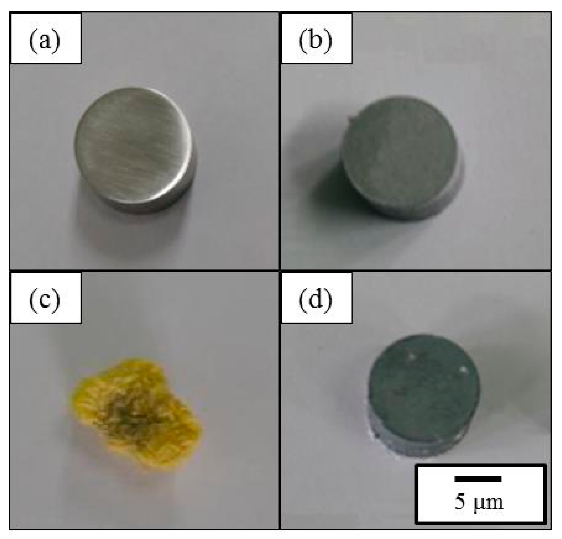
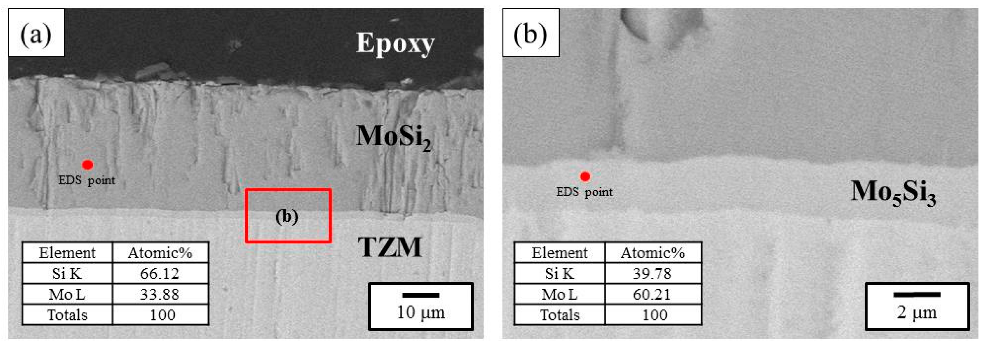
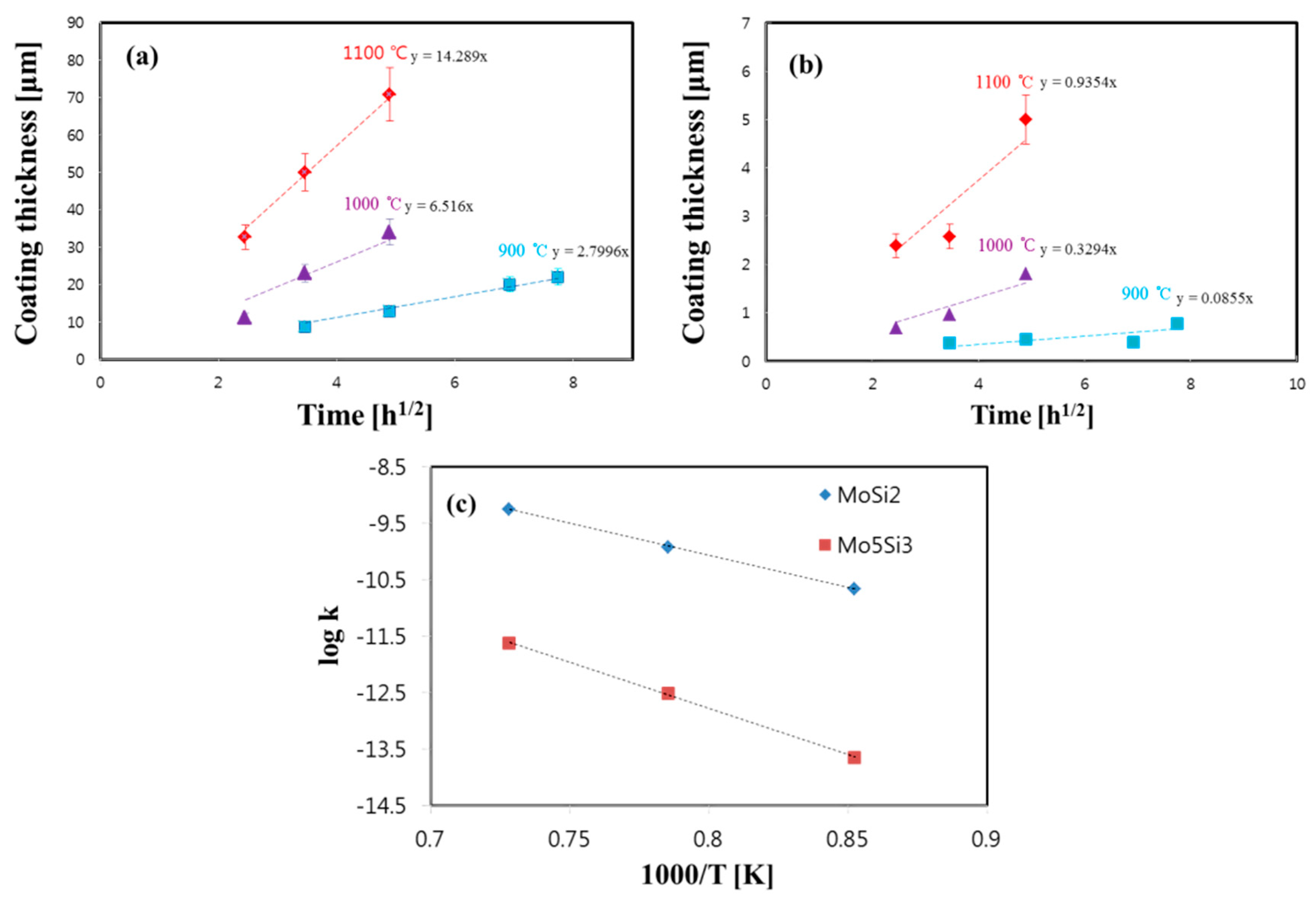
In the case of the Si diffusion coatings, chemical reactions such as Si + Al2O3 + NaF → SiF2 + NaF + Al2O3 may progress during the coating heat treatments. Al2O3 is a ceramic material that is an anti-sintering agent, and the ceramic material does not participate in chemical reactions. When a high-temperature SiF2 activating gas atmosphere is formed through the heat treatment, Si is coated on TZM alloys through gas and solid state diffusion. The additional detailed coating procedure was described elsewhere [7,12,13,14,15]. The outlook images of (a) as-received TZM; (b) the MoSi2-coated TZM; (c) the oxidized TZM without coatings; and (d) the oxidized TZM with Si pack cementation coatings exposed in air at 1350 °C for 50 h are shown in Figure 1. When the coatings were not applied, the TZM alloy turned yellowish in color and lost its initial shape due to the non-protective MoO3 phase formation after oxidation tests. An additional analysis of the oxidation behaviors of the uncoated TZM was not investigated, since the loss of Mo was so obvious [6,7]. However, when the coatings were applied on the TZM alloy, the surface turned dark grey and the initial shape was well maintained after oxidative exposure, implying that the coatings are needed for practical applications. Figure 2 shows a typical cross-section of the coating layer with Si pack cementation coatings at 1100 °C for 6 h. The formation of the coating layer of MoSi2 has been mentioned in previous studies [7,14]. After the Si pack cementation coatings, MoSi2 formed on the surface and formation of a Mo5Si3 layer was observed between the MoSi2 and the TZM alloy (Figure 2b). However, no Mo3Si phase was observed in the current study. It can be argued that the Mo3Si phase might have formed between Mo5Si3 and TZM, but this was not observed possibly due to the nature of low growth kinetics and/or the limitation of the SEM, which corresponds to previous documents by other researchers [18,19]. In order to identify the growth behaviors of the coating layers, the cross-sections of the MoSi2-coated TZM alloys annealed at 1100 °C for 24 h were observed with EBSD, as shown in Figure 3. In order to show a thick coated layer, the specimen coated for the longest time was selected. The MoSi2 grains underwent the preferred directional grain growth with a ~1 μm width, and Mo5Si3 grains developed beneath the MoSi2 grains. The direction of the MoSi2 grain grew towards the surface, and the length of the MoSi2 grain was not consistent, ranging from 10 to 40 μm. Figure 4 shows the growth kinetics of the MoSi2 and the Mo5Si3 phases underneath. The thicknesses of the synthesized MoSi2 and Mo5Si3 phases increased as the coating time was increased. Moreover, the thickness of the coating layer linearly increased with respect to the annealing time. When the coating layer thickness was plotted as x2 = kt, where x denotes thickness (m), t denotes time (s), and the k represents the kinetic parameters. The k values of the MoSi2 phases were larger than that of Mo5Si3. The k values for MoSi2 were estimated to be 2.18 × 10⁻¹¹, 1.17 × 10⁻¹⁰, and 5.60 × 10⁻¹⁰, and those for Mo5Si3 were evaluated to be 2.25 × 10⁻¹⁴, 3.03 × 10⁻¹³, and 2.40 × 10⁻¹² at annealing temperatures of 900, 1000, and 1100 °C, respectively. It was noted that the orders of the current values were similar to the previous results obtained from solid state diffusion annealing [18]. To note, the kinetic parameter (k) also followed the equation, k = ko exp (−Q/RT), where Q is the activation energy (kJ/mol), R is the gas constant (J/K mol), and T (K) is the absolute temperature. The evaluated Q values of MoSi2 and Mo5Si3 phases were 217 and 313 kJ/mol, respectively, which are similar to the results of the previous documents [19].
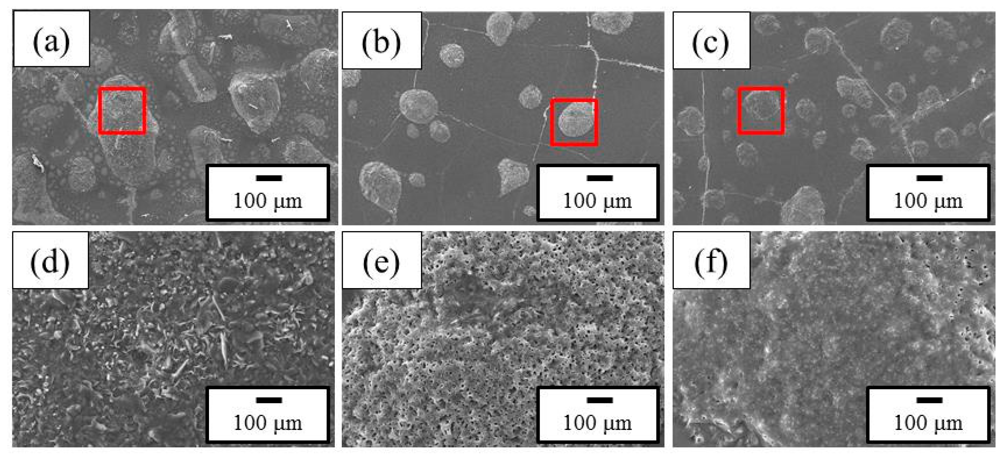
Figure 5 shows SEM micrographs of the surface of the TZM alloy after oxidation at 1350 °C for 5, 20, and 50 h. When the MoSi2 phase-coated TZM was exposed in air, an SiO2 phase formed on the surface. However, with increase in time (i.e., when the thickness of the SiO2 phase was increased), cracks were observed on the surface of the SiO2 layer, possibly due to the coefficient of thermal expansion (CTE) difference between SiO2 and the coated MoSi2 layer [7,19]. It was observed that porous mushroom-shaped oxides were formed at the location of the cracks. The insets in Figure 5a–c are shown in Figure 5d–f, respectively.
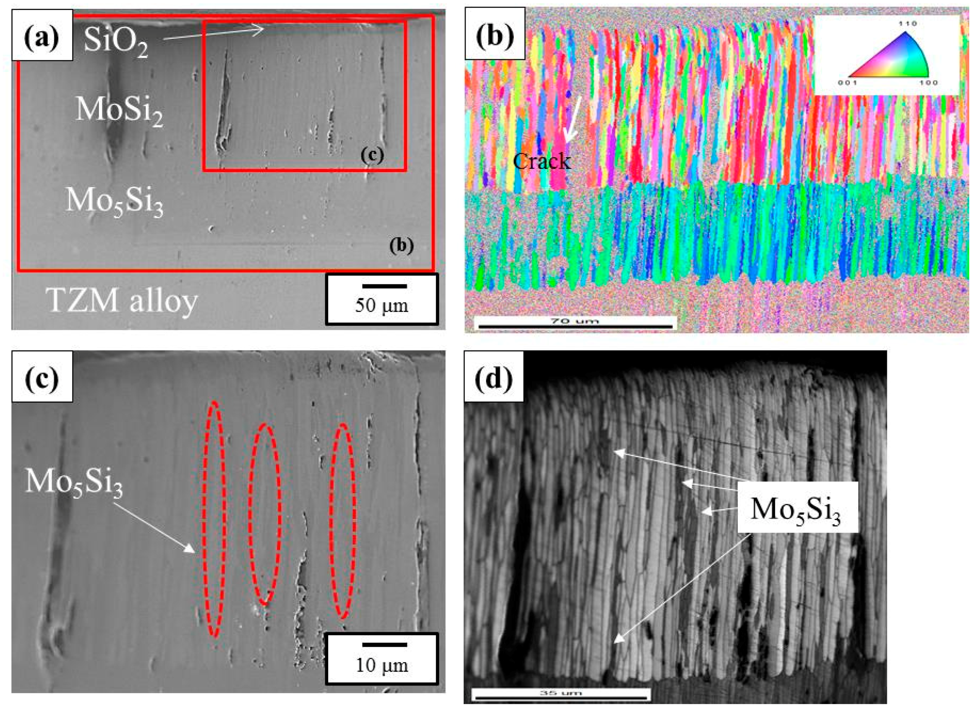
In order to identify the effect of the coating layer on the oxidation exposure, the cross-section of the oxidized specimen was prepared and EBSD was carried out for the coated specimen oxidized at 1350 °C for 20 h. The SEM is shown in Figure 6a, and the EBSD micrograph of the marked large box in Figure 6a is shown in Figure 6b, in which the thickness of Mo5Si3 was about 50 μm, located between the surface MoSi2 and the TZM substrate. Also, the marked small box in Figure 6a is shown in Figure 6c,d. The micrographs show that columnar grains of Mo5Si3 were located inside the coated MoSi2 layer. It was clear that some grains of vertical Mo5Si3 were connected to the Mo5Si3 layer located between the surface MoSi2 and the TZM substrate, as shown in Figure 6d.
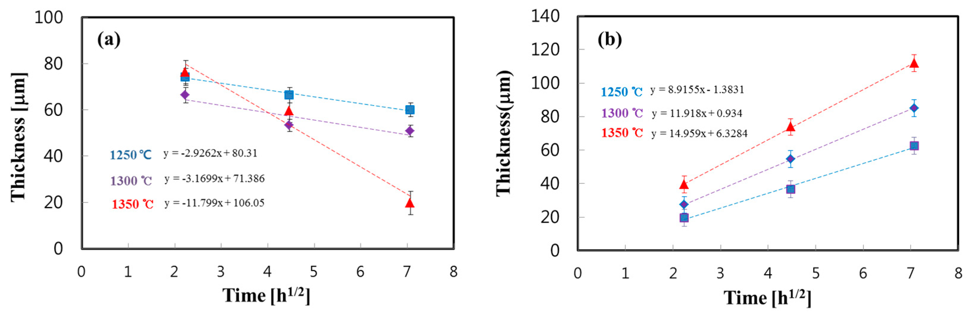
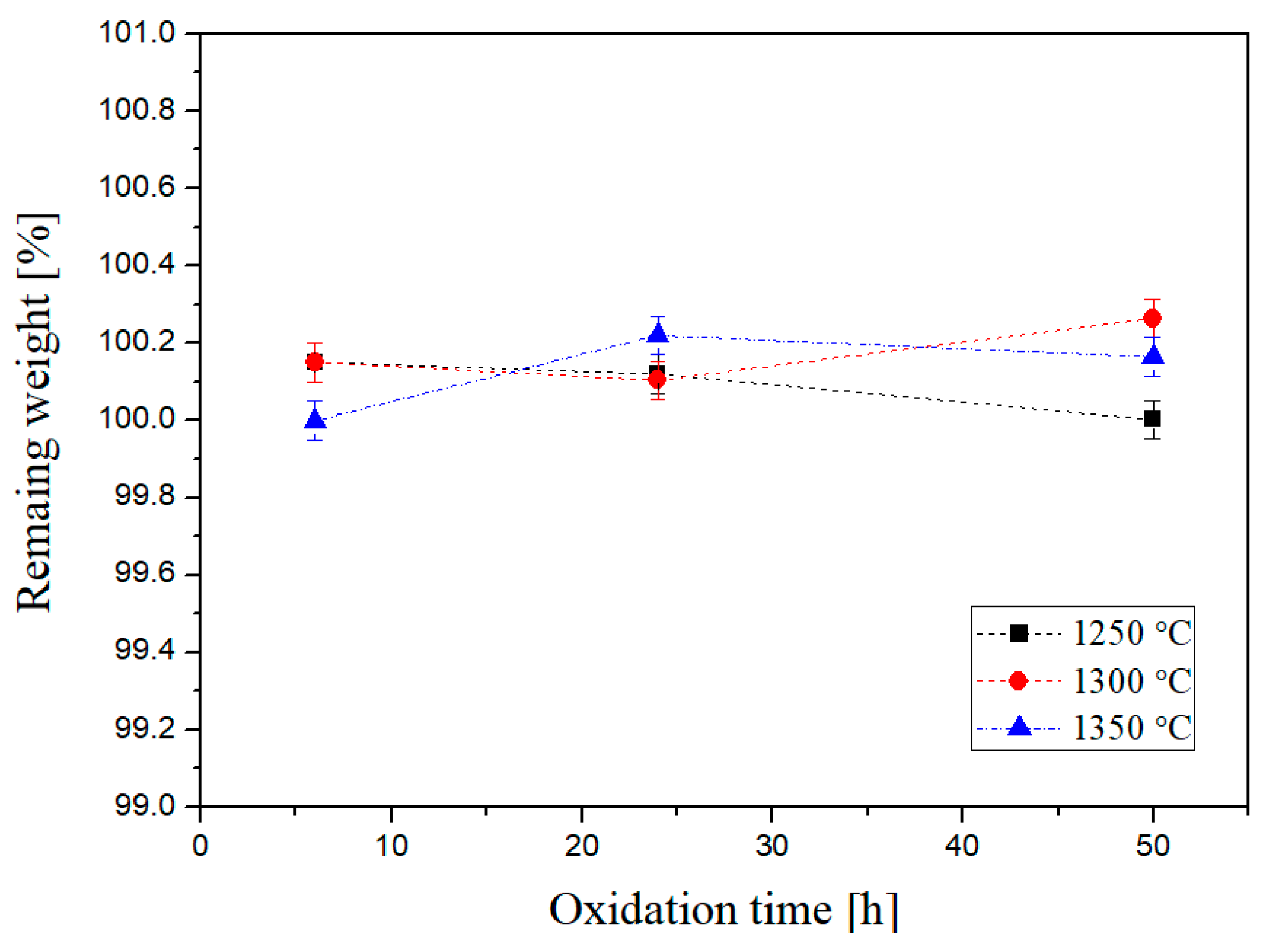
In order to identify the disintegrated kinetics of MoSi2 and the growth kinetics of the Mo5Si3 layer during oxidation exposure, the thicknesses of each phase were measured with respect to the oxidation time, as shown in Figure 7. AS can be seen in the figure, the thickness of the MoSi2 phase decreased, and the reduction rate increased when the oxidation temperature reached the temperature of 1350 °C. At the same time, it was noted that the thickness of the Mo5Si3 phase located between the surface MoSi2 and the TZM substrate increased as the temperature and time of the oxidation exposure was increased. Again, during the oxidation, the k values for the MoSi2 phases (thickness reduction rate) were estimated to be 2.36 × 10⁻¹¹, 2.77 × 10⁻¹¹, and 3.86 × 10⁻¹⁰ (Figure 7a), and the values for Mo5Si3 were evaluated to be 6.17 × 10⁻¹⁰, 3.93 × 10⁻¹⁰, and 2.20 × 10⁻¹⁰ (Figure 7b), at oxidation temperatures of 1250, 1300, and 1350 °C, respectively. The Q value for the decomposition of MoSi2 was estimated as 567 kJ/mol, and that for the Mo5Si3 phase was evaluated as 210 kJ/mol. Figure 8 shows the mass change of the MoSi2-coated TZM alloy after oxidation. Although an increase in mass was observed, the amount of increment was marginal, i.e., the increased values were less than 1 wt %. This is possibly due to the formation of SiO2 at the surface after oxidation tests.
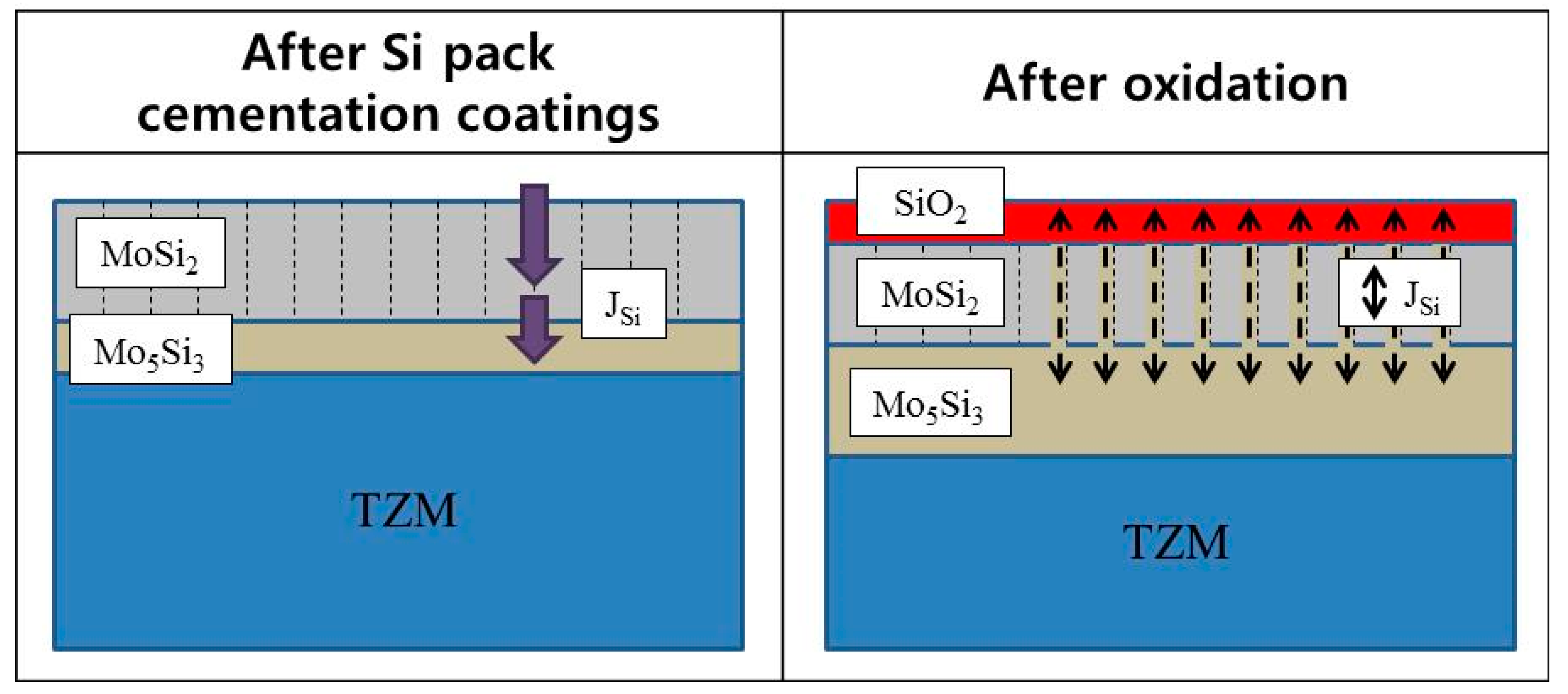
Regarding the columnar growth of Mo5Si3 inside the surface of MoSi2, a possible mechanism is shown in Figure 9. According to a previous report, the growth of the MoSi2 phase is usually observed as a columnar manner, since the MoSi2 phase is synthesized via diffusion reactions [2]. At the same time, when the coated MoSi2 layer was exposed to high temperatures in the presence of air, the surface MoSi2 phase underwent a disintegration reaction, viz. (5/7) MoSi2 (s) + O2 (g) → (1/7) Mo5Si3 + SiO2 (s) [15]. This reaction shows that when the surface SiO2 layer was formed, an Mo5Si3 phase should be produced due to the loss of Si from MoSi2. In this regard, it is possible that the Mo5Si3 phase inside the MoSi2 phase could grow, and Si should move through the grain boundaries of the MoSi2 layer, as shown in Figure 6.
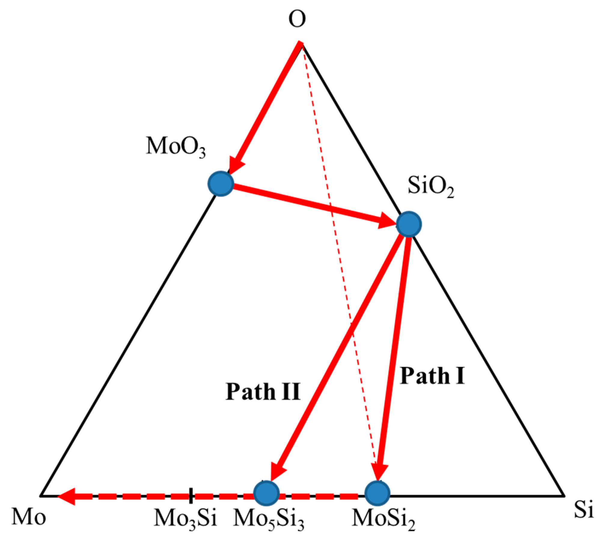
Since phase development during oxidation is related to the diffusion process, it was useful to examine the diffusion pathways with respect to the sequence of the product phases. In regard to the diffusion pathway, some approaches have been proposed under simplified conditions [20,21,22]. The analysis methods included two requirements of the diffusion path. First, the pathway should cross the line connecting the end member compositions in order to satisfy mass balance. Second, a stable path should follow the isothermal phase diagram and coincide with two-phase field tie lines to satisfy local equilibrium. Furthermore, the reaction pathway analyses with finite terminal members and infinite terminal members are totally different situations [23]. For the current cases, probably the diffusion pathway was somehow transient due to the presence of the unstable MoSi2. When the coated MoSi2 phase was exposed to air, two separated reactions of (i) oxygen/MoSi2 ((1/7) MoSi2 + O2 → (1/7) Mo5Si3 + SiO2) and (ii) MoSi2/TZM (2MoSi2 + 6Mo → Mo5Si3 + (Mo3Si)) may occur during oxidation exposure. Then, the MoSi2 layer would eventually disappear as the oxidation time increased due to the loss of Si, i.e., the current case is a diffusion reaction between finite terminal members, and the diffusion pathway might change when the MoSi2 phase disappears.
The observed diffusion pathway of the MoSi2-coated TZM after the oxidation tests was O (MoO3)/SiO2/MoSi2/Mo5Si3/TZM, as shown in Figure 10. When the MoSi2 coating layer was oxidized, Mo initially evaporated to the surface. Then, a SiO2 layer formed on the surface of MoSi2 due to the reaction of oxygen that diffused into MoSi2 and reacted with the Si [7]. According to Figure 10, the diffusion pathway was O (MoO3)/SiO2/MoSi2/Mo5Si3/TZM during oxidation (Path I). When further oxidation occurred, the MoSi2 layer may undergo loss of Si due to the diffusion of Si towards the surface and inside the alloy. In that case, the diffusion pathway may change to O (MoO3)/SiO2/Mo5Si3/TZM (Path II). Furthermore, when the oxidation exposure time is increased, the MoSi2 phase eventually disappears.
While further investigation into factors such as the grain orientations of Mo5Si3 inside the MoSi2 layer is needed, the current observations clearly showed that the disintegration of the outer MoSi2 layer occurs together with both the formation of Mo5Si3 inside the MoSi2 layer and the formation of Mo5Si3 located between the outer MoSi2 layer and the TZM alloy. Also, the lifetime (decomposition of the MoSi2 layer) of the MoSi2 coating layer stability was identified during the exposure of high temperatures under an ambient atmosphere.
4. Conclusions
The growth kinetics and the lifetime kinetics of the coating layers during oxidation were investigated for the MoSi2-coated TZM alloys. When MoSi2 coatings were laid on TZM alloys, the columnar MoSi2 and the Mo5Si3 phases located between the surface of MoSi2 and the substrate TZM alloy were formed. During the coating process, the activation energies of the kinetic parameters of MoSi2 and Mo5Si3 were estimated to be 217 and 313 kJ/mol, respectively. When the MoSi2-coated TZM was oxidized up to 1350 °C, the thickness of the MoSi2 layer decreased, whereas that of the Mo5Si3 phase constantly increased during oxidation exposure. The activation energy of the disintegration parameter of MoSi2 and the growth parameter of Mo5Si3 was estimated to be 567 and 210 kJ/mol, respectively. Also, during the oxidation, the Mo5Si3 phase was also observed inside the surface MoSi2 layer as a columnar shape due to the loss of Si, which formed a surface SiO2 layer. The formation of the SiO2 layer can accelerate the disintegration of the MoSi2 coating layer. The present observations show that the disintegration kinetics of the coated outer MoSi2 layer is meaningful for the estimation of the lifetime of TZM alloys.
Author Contributions
J.S.P. and S.L. conceived and designed the experiments; K.C., Y.J.K., M.K.K. and S.L. performed the experiments; and K.C. and J.S.P. wrote the paper.
Funding
This research was funded by the Agency for Defense Development (contract No. UE105099GD) and Basic Science Research Program through the National Research Foundation of Republic of Korea (NRF) funded by the Ministry of Education, Science, and Technology (contract No. 2016R1D1A1A0991905).
Conflicts of Interest
The authors declare no conflict of interest.
References
- Chakraborty, S.P. Studies on the development of TZM alloy by aluminothermic coreduction process and formation of protective coating over the alloy by plasma spray technique. Int. J. Refract. Met. Hard Mater. 2011, 29, 623–630. [Google Scholar] [CrossRef]
- Majumdar, S.; Sharma, I.G.; Raveendra, S.; Samajdar, I.; Bhargava, P. In situ chemical vapour co-deposition of Al and Si to form diffusion coatings on TZM. Mater. Sci. Eng. A 2008, 492, 211–217. [Google Scholar] [CrossRef]
- Chakraborty, S.P.; Banerjee, S.; Sharma, I.G.; Suri, A.K. Development of silicide coating over molybdenum based refractory alloy and its characterization. J. Nucl. Mater. 2010, 403, 152–159. [Google Scholar] [CrossRef]
- Chakraborty, S.P.; Banerjee, S.; Singh, K.; Sharma, I.G.; Grover, A.K.; Suri, A.K. Studies on the development of protective coating on TZM alloy and its subsequent characterization. J. Mater. Proc. Technol. 2008, 207, 240–247. [Google Scholar] [CrossRef]
- Cockeram, B.V. The mechanical properties and fracture mechanisms of wrought low carbon arc cast (LCAC), molybdenum–0.5pct titanium–0.1pct zirconium (TZM), and oxide dispersion strengthened (ODS) molybdenum flat products. Mater. Sci. Eng. A 2006, 418, 120–136. [Google Scholar] [CrossRef]
- Smolik, G.R.; Petti, D.A.; Schuetz, S.T.J. Oxidation and volatilization of TZM alloy in air. J. Nucl. Mater. 2000, 283, 1458–1462. [Google Scholar] [CrossRef] [Green Version]
- Majumdar, S.; Sharma, I.G. Oxidation behavior of MoSi2 and Mo(Si, Al)2 coated Mo–0.5Ti–0.1Zr–0.02C alloy. Intermetallics 2011, 19, 541–545. [Google Scholar] [CrossRef]
- Park, J.S.; Sakidja, R.; Perepezko, J.H. Coating designs for oxidation control of Mo-Si-B alloys. Scr. Mater. 2002, 46, 765–770. [Google Scholar] [CrossRef]
- Nomura, N.; Suzuki, T.; Yoshimi, K.; Hanada, S. Microstructure and oxidation resistance of a plasma sprayed Mo-Si-B multiphase alloy coating. Intermetallics 2003, 11, 735–742. [Google Scholar] [CrossRef]
- Lange, A.; Braun, R. Magnetron-sputtered oxidation protection coatings for Mo-Si-B alloys. Corros. Sci. 2014, 84, 74–84. [Google Scholar] [CrossRef]
- Riedl, H.; Vieweg, A.; Limbeck, A.; Kalaš, J.; Arndt, M.; Polcik, P.; Euchner, H.; Bartosik, M.; Mayrhofer, P.H. Thermal stability and mechanical properties of boron enhanced Mo–Si coatings. Surf. Coat. Technol. 2015, 280, 282–290. [Google Scholar] [CrossRef]
- Park, J.S.; Kim, J.M.; Son, Y.I. Oxidation response of Al coated TZM alloys under dynamic plasma flame. Int. J. Refract. Met. Hard Mater. 2013, 41, 110–114. [Google Scholar] [CrossRef]
- Sakidja, R.; Rioult, F.; Werner, J.; Perepezko, J.H. Aluminum pack cementation of Mo-Si-B alloys. Scr. Mater. 2006, 55, 903–906. [Google Scholar] [CrossRef]
- Park, J.S.; Kim, J.M.; Kim, H.Y.; Lee, J.S.; Oh, I.H.; Kang, C.S. Surface protection effect of diffusion pack cementation process by Al-Si powders with chloride activator on magnesium and its alloys. Mater. Trans. 2008, 49, 1048–1051. [Google Scholar] [CrossRef]
- Park, J.S.; Kim, J.M.; Cho, S.H.; Kim, Y.I.; Kim, D.S. Oxidation of MoSi2-coated and uncoated TZM (Mo0.5Ti0.1Zr0.02C) alloys under high temperature plasma flame. Mater. Trans. 2013, 54, 1517–1523. [Google Scholar] [CrossRef]
- Schilephake, D.; Gombola, C.; Kauffmann, A.; Heilmaier, M.; Perepezko, J.H. Enhanced oxidation resistance of Mo-Si-B-Ti alloys by pack cementation. Oxid. Met. 2017, 88, 267–277. [Google Scholar] [CrossRef]
- Perepezko, J.H. High temperature environmental resistant Mo-Si-B based coatings. Int. J. Refract. Met. Hard Mater. 2018, 71, 246–254. [Google Scholar] [CrossRef]
- Tortorici, P.C.; Dayananda, M.A. Diffusion structures in Mo vs Si solid-solid diffusion couples. Scr. Mater. 1998, 38, 1863–1969. [Google Scholar] [CrossRef]
- Yoon, J.K.; Byun, J.Y.; Kim, G.H.; Kim, J.S.; Choi, C.S. Growth kinetics of three Mo-Silicide layers formed by chemical vapor deposition of Si on Mo substrate. Surf. Coat. Technol. 2002, 155, 85–95. [Google Scholar] [CrossRef]
- Yanagihara, K.; Przybylski, K.; Maruyama, T. The role of microstructure on pesting during oxidation of MoSi2 and Mo(Si,Al)2 at 773 K. Oxid. Met. 1997, 47, 277–293. [Google Scholar] [CrossRef]
- Van Loo, F.J. Multiphase diffusion in binary and ternary solid-state systems. Prog. Solid State Chem. 1990, 20, 47–99. [Google Scholar] [CrossRef]
- Kirkaldy, J.S.; Young, D.J. Diffusion in the Condensed State; The Institute of Metals: London, UK, 1988; pp. 361–400. [Google Scholar]
- Perepezko, J.H.; da Silva Bassani, M.H.; Park, J.S.; Edelstein, A.S.; Everett, R.K. Diffusional reactions in composite synthesis. Mater. Sci. Eng. A 1995, 195, 1–11. [Google Scholar] [CrossRef]
Figure 1.
Surface image of (a) the as-received TZM alloy; (b) after coating the TZM alloy at 1100 °C for 6 h; (c) oxidized TZM alloy at 1300 °C for 50 h; and (d) MoSi2-coated TZM alloy oxidized at 1350 °C for 50 h.
Figure 1.
Surface image of (a) the as-received TZM alloy; (b) after coating the TZM alloy at 1100 °C for 6 h; (c) oxidized TZM alloy at 1300 °C for 50 h; and (d) MoSi2-coated TZM alloy oxidized at 1350 °C for 50 h.

Figure 2.
(a) Cross-section of MoSi2-coated TZM alloys at 1100 °C for 6 h; (b) shows the enlargement of the inset in (a).
Figure 2.
(a) Cross-section of MoSi2-coated TZM alloys at 1100 °C for 6 h; (b) shows the enlargement of the inset in (a).

Figure 3.
(a) Cross-section of MoSi2-coated TZM alloys at 1100 °C for 24 h; (b) shows the electron backscatter diffraction (EBSD) micrographs of the marked area in (a).
Figure 3.
(a) Cross-section of MoSi2-coated TZM alloys at 1100 °C for 24 h; (b) shows the electron backscatter diffraction (EBSD) micrographs of the marked area in (a).

Figure 4.
Growth kinetics of (a) MoSi2; (b) Mo5Si3 layer; and (c) kinetic parameters (k) with respect to exposure temperature.
Figure 4.
Growth kinetics of (a) MoSi2; (b) Mo5Si3 layer; and (c) kinetic parameters (k) with respect to exposure temperature.

Figure 5.
Surface morphology of MoSi2-coated TZM alloys oxidized at 1350 °C for (a) 5, (b) 20, and (c) 50 h; (d–f) show the enlargements of the marked areas in (a–c), respectively.
Figure 5.
Surface morphology of MoSi2-coated TZM alloys oxidized at 1350 °C for (a) 5, (b) 20, and (c) 50 h; (d–f) show the enlargements of the marked areas in (a–c), respectively.

Figure 6.
Cross-sectional SEM of the MoSi2-coated TZM alloy oxidized at 1350 °C for 20 h. (a) SEM; (b) EBSD micrograph of the large area marked in (a); (c) the enlargement of the small inset in (a); and (d) image with black and white contrast of (c).
Figure 6.
Cross-sectional SEM of the MoSi2-coated TZM alloy oxidized at 1350 °C for 20 h. (a) SEM; (b) EBSD micrograph of the large area marked in (a); (c) the enlargement of the small inset in (a); and (d) image with black and white contrast of (c).

Figure 7.
Layer kinetics of (a) MoSi2 layer, (b) Mo5Si3 layer during oxidation exposure with respect to the exposure time; (c) shows the log k vs. inverse temperature plot.
Figure 7.
Layer kinetics of (a) MoSi2 layer, (b) Mo5Si3 layer during oxidation exposure with respect to the exposure time; (c) shows the log k vs. inverse temperature plot.


Figure 8.
Remaining weight percent of TZM alloys after oxidation exposure at the designated temperature and time.
Figure 8.
Remaining weight percent of TZM alloys after oxidation exposure at the designated temperature and time.

Figure 9.
Schematic illustration of MoSi2 coatings and the formation of Mo5Si3 phase inside the MoSi2 layer after oxidation.
Figure 9.
Schematic illustration of MoSi2 coatings and the formation of Mo5Si3 phase inside the MoSi2 layer after oxidation.

Figure 10.
Diffusion pathways of the oxidation of MoSi2 (diffusion path I: O (MoO3)/SiO2/MoSi2/Mo5Si3/TZM; diffusion path II: O (MoO3)/SiO2/Mo5Si3/TZM).
Figure 10.
Diffusion pathways of the oxidation of MoSi2 (diffusion path I: O (MoO3)/SiO2/MoSi2/Mo5Si3/TZM; diffusion path II: O (MoO3)/SiO2/Mo5Si3/TZM).

© 2018 by the authors. Licensee MDPI, Basel, Switzerland. This article is an open access article distributed under the terms and conditions of the Creative Commons Attribution (CC BY) license (http://creativecommons.org/licenses/by/4.0/).
Share and Cite
MDPI and ACS Style
Choi, K.; Kim, Y.J.; Kim, M.K.; Lee, S.; Lee, S.; Park, J.S. Oxidation Behavior of MoSi2-Coated TZM Alloys during Isothermal Exposure at High Temperatures. Coatings 2018, 8, 218. https://doi.org/10.3390/coatings8060218
AMA Style
Choi K, Kim YJ, Kim MK, Lee S, Lee S, Park JS. Oxidation Behavior of MoSi2-Coated TZM Alloys during Isothermal Exposure at High Temperatures. Coatings. 2018; 8(6):218. https://doi.org/10.3390/coatings8060218
Chicago/Turabian StyleChoi, Kwangsu, Young Joo Kim, Min Kyu Kim, Sangyeob Lee, Seong Lee, and Joon Sik Park. 2018. "Oxidation Behavior of MoSi2-Coated TZM Alloys during Isothermal Exposure at High Temperatures" Coatings 8, no. 6: 218. https://doi.org/10.3390/coatings8060218
Note that from the first issue of 2016, this journal uses article numbers instead of page numbers. See further details here.