Article

Chromium Carbide Growth by Direct Liquid Injection Chemical Vapor Deposition in Long and Narrow Tubes, Experiments, Modeling and Simulation

1
DEN Service d’Etudes Analytiques et de Réactivité des Surfaces (SEARS), CEA, Université Paris-Saclay, 91191 Gif Sur Yvette, France
2
CIRIMAT, Université de Toulouse, CNRS/INPT/UPS, 4 allée E. Monso, 31030 Toulouse, France
3
Cross-Cutting Program on Materials and Processes Skills Department, CEA, Université Paris-Saclay, 91191 Gif Sur Yvette, France
4
Institute of Engineering, Université Grenoble Alps, CNRS, Grenoble INP, SIMAP, 38000 Grenoble, France
*
Author to whom correspondence should be addressed.
Coatings 2018, 8(6), 220; https://doi.org/10.3390/coatings8060220
Submission received: 24 May 2018 / Revised: 7 June 2018 / Accepted: 8 June 2018 / Published: 13 June 2018
(This article belongs to the Special Issue Chemical Vapor Deposition 2018)

Abstract

:
Chromium carbide layers were deposited using liquid-injection metal-organic chemical vapor deposition inside long (0.3 to 1 m) and narrow (8 to 24 mm in diameter) metallic tubes. The deposition was carried out using a molecular single-source, bis(benzene)chromium (BBC), as representative of the bis(arene)metal family diluted in toluene and injected with N2 as carrier gas. A multicomponent mass transport model for the simulation of the coupled fluid flow, heat transfer and chemistry was built. The kinetic mechanism of the growth of CrCx films was developed with the help of large-scale experiments to study the depletion of the precursors along the inner wall of the tube. The model fits well in the 400–550 °C temperature range and in the 1.3 × 10² to 7 × 10³ Pa pressure range. The pressure is shown to have a pronounced effect on the deposition rate and thickness uniformity of the resulting coating. Below 525 °C the structure, composition and morphology of the films are not affected by changes of total pressure or deposition temperature. The coatings are amorphous and their Cr:C ratio is about 2:1, i.e., intermediate between Cr7C3 and Cr3C2. The model was applied to the design of a long reactor (1 m), with a double injection successively and alternatively undertaken at each end to ensure the best uniformity with sufficient thickness. This innovative concept can be used to optimize industrial deposition processes inside long and narrow tubes and channels.

1. Introduction

During their working lifetime, tools and machinery components are subjected to intensive degradation due to the combination of abrasive wear, corrosion and oxidation. Because of its hardness and high temperature stability, chromium carbide thin films (CrCx) are suitable to increase the performance and extend the lifetime of metallic alloys. Cr-based hard coatings are mainly deposited by physical vapor deposition (PVD) [1], chemical vapor deposition (CVD) [2] or thermo-reactive deposition (TRD) [3]. CVD is considered an effective process to apply thin protective layers because of its ability to conformally coat complex geometries and its relative ease of control of the growth rate and the microstructure [4,5]. Furthermore, the use of metalorganic compounds as precursors in metalorganic chemical vapor deposition process (MOCVD) has several advantages: (i) reducing the processing temperature needed to avoid structural and dimensional changes of the substrate; (ii) lowering toxicity and corrosive properties when compared to hydrides or chlorides precursors; (iii) benefiting from a wide choice of metalorganic compounds, which make it possible to deposit specific phases that cannot be grown by other techniques; and (iv) for energy saving in a large-scale process.
The protection of the inner walls of long metallic tubes can improve their lifetime in applications where their internal surface is exposed to corrosive, oxidative and abrasive environments as in oil, gas, chemical and nuclear industries where piping delivers corrosive materials or are implemented in extreme environments. Coatings for long and narrow channels like plate heat exchangers [6] or clad tubes in the nuclear industry can be optimized in terms of, microstructure, growth rate and thickness uniformity.
There are at least two technical difficulties that must be overcome to deposit a protective coating with uniform thickness on the inner walls of long tubes exhibiting a high aspect ratio (AR = L/ID > 100) as piping: (i) the great length (L) to be covered and (ii) the small internal diameter (ID) of the tubes. In the case of long straight tubes, the first issue can be solved by a continuous deposition process with displacement of the tube, or of the deposition zone, on the basis of known methods. For instance, many in-line or roll-to-roll CVD reactors were described to coat C fibers moving at constant speed with BN [7,8] and W filaments with TaC [9], or for continuous deposition of functional layers on flexible substrates as Nb3Ge [10] or more recently graphene [11]. These continuous CVD processes in belt furnaces were extended to mass production of many others thin films as ZnO [12] and are even implemented for photovoltaic Si at an industrial level [13]. Some of these techniques could be adapted for long straight tubes.
Regarding the inner diameter of tubes, when it is sufficiently large, deposition methods other than CVD can be used. For instance, for diameter larger than 3.5 cm a hollow cathode plasma immersion ion process can be used as demonstrated for DLC-Si composite coating in 304 stainless steel pipe, but this demonstration was made only over a length of 30 cm [14]. Modeling and optimization of chemical vapor infiltration (CVI) on the internal surface of porous preforms was a fundamental basis for producing CVD parts for heat-exchanger tubes but the sample reported had a large diameter (10 cm) for only 45 cm long, which allowed the use of a central, concentric reactant injector fixed along the tube [15]. Also, a fundamental approach was reported for CVD of Si3N4 tube-shaped substrates with a low AR (12 mm ID) [16]. For smaller diameters and longer tubes, it is still a challenge and CVD techniques are certainly the most appropriate processes for the growth of relatively thick and uniform coatings.
For millimeter ID and lengths greater than one meter a dynamic set-up, i.e., continuous CVD coupled to the displacement of the deposition zone, seems to be a good solution. Thus, after preliminary runs under stationary conditions [17], TiN films were deposited on the inner wall of long steel tubes by moving the furnace [18]. Also by moving the heating system, SiC thick coatings were grown by continuous CVD on the inner wall of a silica tube [19], Cu was grown by MOCVD on the inner surface of a hollow substrate [20] and Cr2O3 was deposited inside a zircaloy tube 8 mm ID by MOCVD [21]. VC was deposited on the interior surface of steel tubes by moving simultaneously the reactant gas inlet device and the heated zone produced by an radio-frequency (RF) coil [22]. However, for the growth of coatings of a few micrometers thick continuous CVD requires very high growth rates because the substrate is moved at a constant speed across the reaction zone. Also, contamination of the coating by solid by-products deposited in low-temperature zones can have dramatic effects on adhesion [17]. Furthermore, it is necessary to control the movement systems as a conveyor or reels, which increases the cost of the process.
If we exclude vapor deposition techniques with displacement, ALD (Atomic Layer Deposition) processes can be considered because they are well known to conformally coat complex shapes. Thus, a theoretical study of ALD of Al thin films on inner wall of rectangular pipe with AR = 50 was reported [23]. However, this modeling has not been confirmed experimentally and the aspect ratio considered was too low to respond to larger needs in piping. Recently corrosion mitigation coatings were deposited by ALD on the interior surface in a complex cooling circuit [24]. However, ALD is essentially adapted to the growth of metal oxides and it still suffers from very low growth rates, which is problematic for developing protective coatings about 10 µm thick.
In stationary conditions, i.e., without moving the reaction zone, CVD coatings grown on inner walls of tubes under isothermal conditions exhibit a maximum thickness near the inlet, then a continuous decrease of the thickness occurs due to depletion of the reactive gas phase. For lengths shorter than a few tens of centimeters, CVD conditions can be found experimentally to obtain a satisfactory uniformity of the thickness along the tube as shown for CNT layers grown inside stainless tubes 40 cm long [25] and for SiCxOy films deposited inside quartz tubes about 60 cm long (8 mm ID) [26]. However, these lengths are generally not sufficient for applications. For instance, protective coating on the inner surface of nuclear fuel claddings requires uniformity of thickness over a length of about 4 m. For this application, in the 1980s, Cr coatings as oxygen getter [27] and boron-containing coatings as neutron absorber [28] were deposited by atmospheric pressure CVD inside sections of cladding tubes about 30 cm long. We have now learned from the modeling and optimization of such processes that low pressure is required to improve uniformity in the axis of the tube. For instance, this was demonstrated by the recent kinetic modeling of Ta CVD in long narrow channels with a high aspect ratio (AR = 500) [6].
This paper presents the growth of CrCx thin films using a MOCVD process coupled with direct-pulsed liquid injection (DLI) of the precursor [29]. Experimental results relating to morphology, microstructure and composition are presented to introduce the coating challenge in long and narrow tubes. A parametric study has been carried out to describe the influence of operating conditions on coating uniformity inside tubes as long as 1 m and as narrow as 8 mm ID. A kinetic growth model adapted to this large-scale process has been developed and simulations were used to validate the model and design upscaling. The rate and efficiency of the process are strongly dependent on reaction kinetics, fluid flow, heat transfer and mass transport in the reaction zone. An in-depth understanding of such reaction-transport phenomena requires computational fluid dynamics (CFD) models that are able to predict growth rate and its uniformity over complex geometries [30,31,32,33,34,35,36,37,38,39,40,41,42,43,44,45,46].
The practical objectives are (i) to identify operating conditions leading to the growth of uniform films over the interior of long tubes and (ii) to predict the spatial distribution of gas-phase species along the tube, which is inherently difficult to probe by in situ non-intrusive techniques.

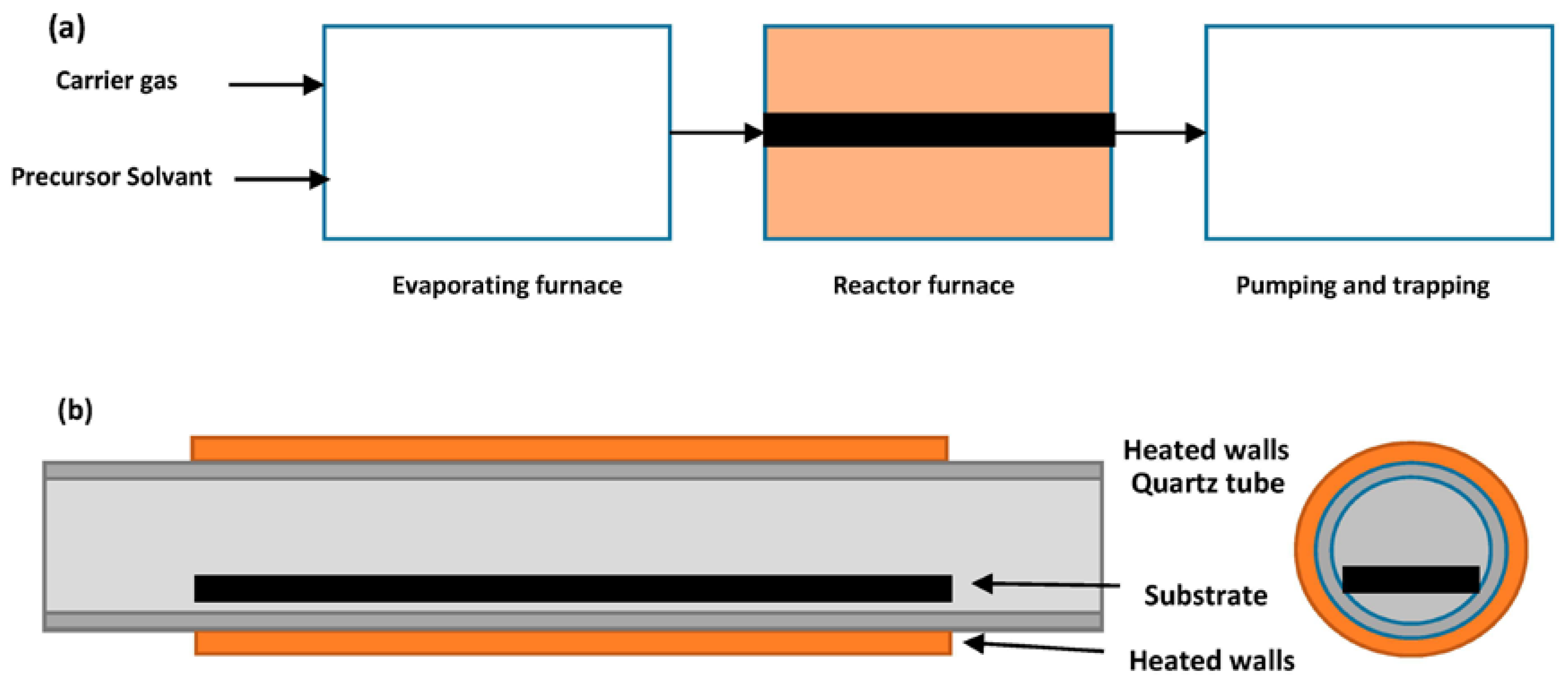
2. Experimental Procedure

The schematic representation of the reactor is shown in Figure 1 and more details can be found in a previous paper [47]. A hot-wall horizontal reactor equipped with the DLI system from Kemstream Company (Montpellier, France) was used. The precursors, bis(benzene)chromium (BBC, a solid compound) or bis(ethylbenzene)chromium (BEBC, a liquid) dissolved (or diluted) in toluene were injected in a flash vaporization chamber maintained at about 180 °C. The precursor solution in toluene was injected in pulsed mode, typically with a frequency of 10 or 20 Hz and an opening time of the injector varying from 0.5 to 5 ms depending on the different CVD runs. The mass flow rate of the precursor is calculated from these operating conditions. These injection conditions were chosen according to our previous work [29] to form a mist of very fine droplets necessary to obtain a flash evaporation in the vaporization chamber. Then, the reactive vapor was transported with a N2 flow rate of 500 sccm and was heated at approximately 180 °C before entering the deposition chamber to prevent condensation.
The precursor vapor is delivered to the reactor inlet and flow inside long and narrow tubes (0.3 to 1 m) placed in a resistively heated furnace. Two types of tubes were used: (i) a quartz tube, 0.3 m long and 24 mm diameter with a test plate of 20 cm long (Figure 1b); and (ii) a metallic tube 1 m long with 8 mm of diameter. In the first case, thickness measurements were made by cutting samples along 20 cm of the flat test substrate. In the second case, the coating thickness was directly measured on cross-sections of the metallic tube. The composition range of BBC in the carrier nitrogen gas varied from 0.1% to 0.6%, the reactor pressure range was from 7 × 10² to 7 × 10³ Pa, and the temperature range of the substrate was from 400 to 550 °C. The crystal structure of the films was analyzed by X-ray diffraction (XRD). Surface morphology was studied by scanning electron microscopy (SEM). Electron probe microanalysis (EPMA) was used to determine the composition of the films.

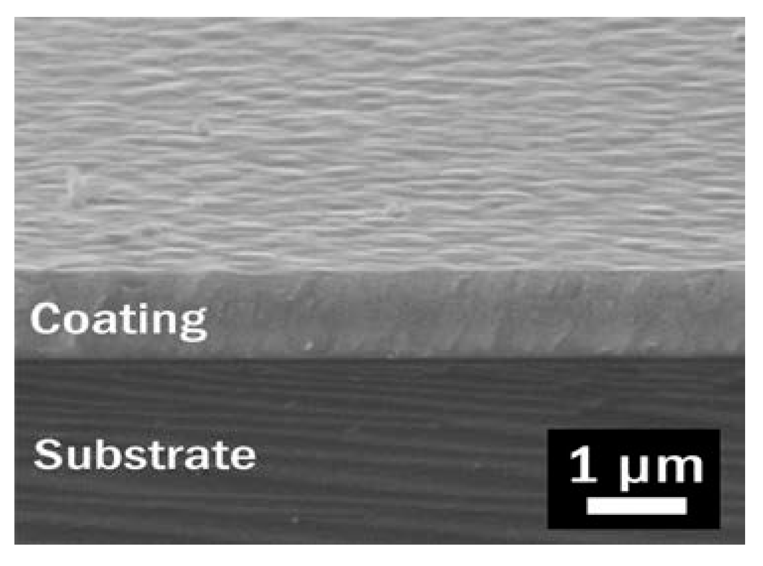
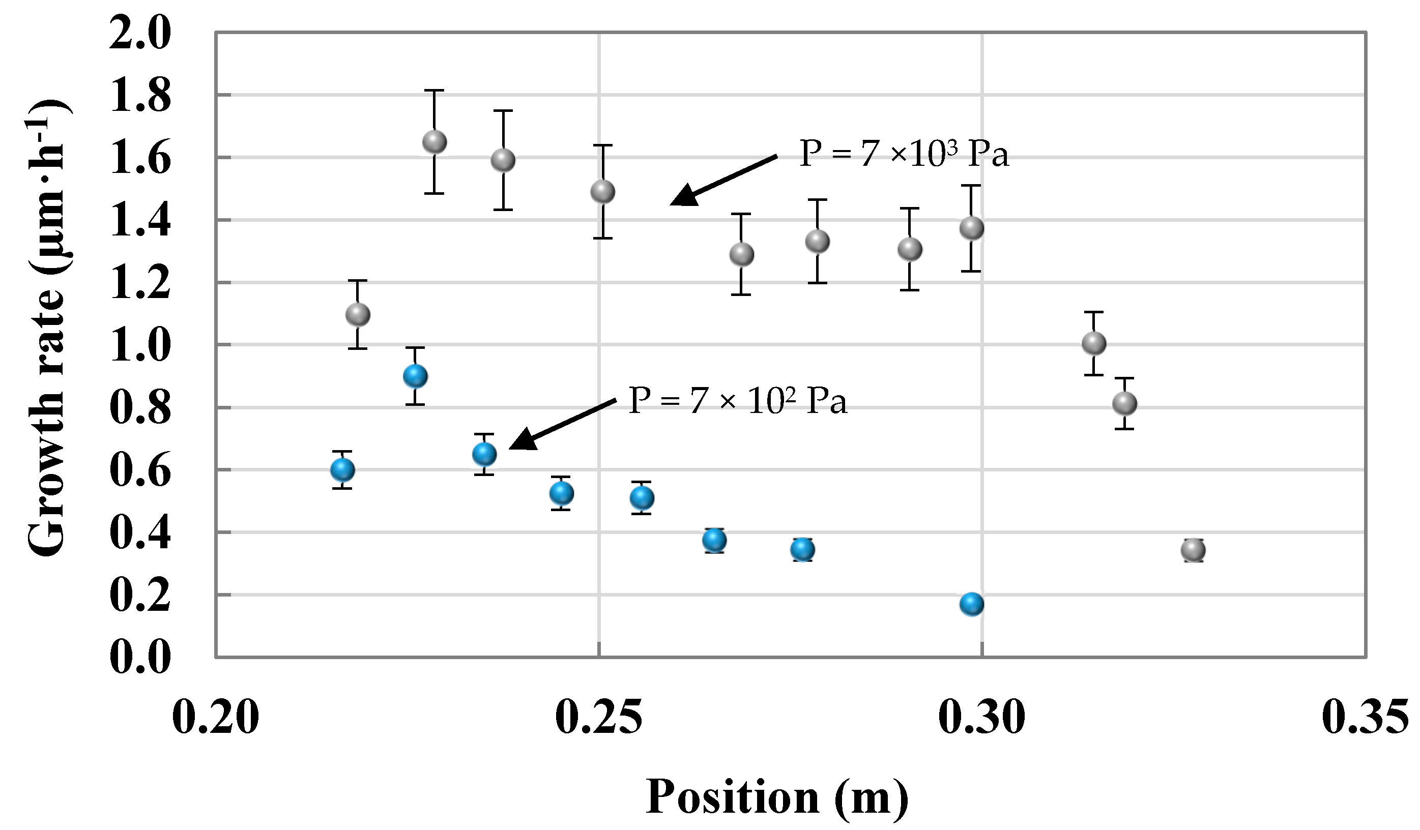
3. Experimental Results

The emerging DLI technique is particularly convenient to feed CVD reactors with high flow rates of precursors exhibiting a poor volatility [47]. Organic solvents are commonly employed to solubilize solid metalorganic compounds or adjust the properties of liquids such as viscosity. It was shown in previous studies [29,47] that an adequate oxygen-free solvent, taking into account reactivity, toxicity, cost, commercial availability and safety, is toluene (C6H5CH3). This solvent belongs to the same family as the ligands of the precursor and it does not react with it. Furthermore, the corresponding saturation concentration is high enough to deliver high flow rates of the precursor.
All CrCx coatings deposited inside tubes in the 350–525 °C temperature range and 1.3 × 10² to 7 × 10³ Pa pressure range are amorphous. They are dense, with no apparent texture (Figure 2). They have a metallic glossy appearance and a mirror-like surface morphology. In the temperature and pressure ranges under investigation, they exhibit a constant stoichiometry with a ratio Cr:C of 2:1, which is intermediate between Cr7C3 and Cr3C2. They always contain small amounts of oxygen (<3 at. %). More details can be found in previous works of the authors [29].
The deposition rate varies along the length of the substrate (Figure 1b) due to precursor depletion (Figure 3). In typical conditions, for tubes of 30 mm in diameter, the maximum growth rate is around 1.6 µm·h−1 for a temperature of 450 °C and a pressure of 7 × 10³ Pa. At the entrance and in the first centimeters, the growth rate increases due to the combined effects of the reactive flow and temperature fields. Then, it rapidly decreases due to depletion of the precursor. When the pressure is decreased to 7 × 10² Pa, the deposition rate decreases but is more homogeneous along the tube.
This overview of the main characteristics of CrCx coatings deposited inside tubes introduces the challenge that must be solved: a homogeneous deposition along long (1 m) and narrow (8 mm) tube. The next section is devoted to multicomponent mass transport modeling and focused experiments to design the best operating conditions leading to the most uniform coating inside long and narrow tubes.

4. Transport Modeling and Databases

4.1. Equations

The governing equations describing flow dynamics, heat transfer and mass transport include continuity, momentum, energy and species balance.
Continuity
ρ v = 0
Momentum balance
( ρ v v ) = τ _ _ P + ρ g τ _ _ = μ ( v + ( v ) t ) 2 3 μ ( v ) I _ _
Energy balance
c p ( ρ v T ) = ( λ T ) + ( R T i = 1 N D i T M i x i x i ) + i = 1 N H i M i J i i = 1 N k = 1 K H i υ i k ( R k g R k g )   i = 1 , N
Species transport
( ρ v ω i ) = J i + M i k = 1 K υ i k ( R k g R k g )   i = 1 , N J i c = j = 1 N ( ρ D i j ) x j     i = 1 , N J i T = D i T T T     i = 1 , N
Ideal gas law
ρ = P M R T
Deposition rate
R s i = J i · n = J i c · n + J i T · n     i = 1 , N
Governing equations where ρ ,   μ ,   λ ,   c p are the density, viscosity, thermal conductivity and specific heat of the gas mixture, g the gravity vector, P the pressure, v the velocity, T the gas temperature, ω i the mass fraction of specie i, x i the mole fraction of specie i, D i T its thermal diffusion coefficient,   H i its enthalpy, ν i k its stoichiometric coefficient in gas phase reaction k, D i j the matrix of diffusion coefficients for N species, R k g the reaction rate of that reaction, R s i the deposition rate of specie i, R the universal gas constant and M the molar mass of the mixture.
The flow is laminar, obeys the ideal gas law, and steady-state conditions prevails [48]. Precursor vapors are very diluted in the carried gas and solvent vapor (more than 99% of the gaseous phase) so values of the transport properties can be calculated by the kinetic theory of dilute gas [48,49]. The boundary conditions for velocity, temperature and species concentration are the following: The temperature and concentration distribution are uniform at the inlet of the tube. On reactive surfaces, Equation (6) is applied for the deposition rate. The temperature of the reactor walls is specified from measurements. All simulations were performed using the CFD-ACE software package (ESI Group, Paris, France).
The properties of the individual species and binary diffusion coefficients have been estimated using gas kinetic theory [48,49] (Section 4.4). Thermodynamic data were evaluated and discussed (Section 4.4). Homogeneous reactions R k g have been evaluated and discussed in the form of an Arrhenius law (Section 4.3):
k k = a k T β k exp ( E a k R T )
where k k is the kinetic constant of reaction k, β k the temperature exponent, and E a k the activation energy of reaction k.
Surface reactions have been evaluated and discussed by using reactive sticking coefficients for monomolecular reactions (Section 4.3). The sticking coefficient (Sci for species i) is the fraction of molecules incorporated into the film upon collision with the surface and the deposition rate R s i of specie i is:
R s i = ρ S c i R T 2 π M i ω i
with such a database, it will be possible for any engineer to compute velocity, temperature and concentration fields, and deposition rate in the range of operating conditions that are investigated.

4.2. Kinetic Pathways: Study of the Solvent

Thermal decomposition of bis(arene)Cr molecules like Cr(C6H6)2 (BBC) and Cr(C6H5C2H5)2 (BEBC) occurs in the 350–550 °C range to yield chromium carbide films. Toluene (C6H5CH3) is the solvent. On-line mass spectrometry analysis had shown that benzene (83 mol. %), hydrogen (11 mol. %) and traces of other hydrocarbons (6 mol. %) were the major gaseous byproducts formed during MOCVD using BBC [50]. Other works on bis(arene)Cr compounds have confirmed that aromatic hydrocarbons and hydrogen originating from the ligands are the main gaseous by-products.
The thermal decomposition of various solvent including aromatic compounds has been studied under conditions comparable to those applied for the growth of the coatings. Experiments under low pressure involving only a flow of toluene diluted in N2 as carrier gas have shown that the solvent decomposition occurs at temperatures higher than 600 °C (Figure 4) while its decomposition have been predicted by thermodynamic simulation at equilibrium [29]. Indeed, quartz samples were placed in the reactor during the pyrolysis of pure toluene vapor at different temperatures. When the temperature increases, the decomposition of toluene leads to a thin film of carbon giving a light gray tint to the sample, which became darker and darker as the pyrolytic-C film thickness increased. This result is illustrated in Figure 4 by the increase of absorption in the visible range. At temperatures lower than 600 °C, the transmittance of the sample is the same as the bare quartz sample. Therefore, benzene (C6H6), ethylbenzene (C6H5C2H5) and toluene (C6H5CH3) are not decomposed under 600 °C, i.e., in the DLI–MOCVD of this work. The simulation of kinetic pathways of toluene decomposition proposed by Brioukov et al. [50] gives the same conclusions.
At this stage, the first conclusion for the development of the kinetic model is that toluene, used as a solvent for the dilution of BBC in the injector, and benzene, the ligand of BBC released as the main reaction byproduct of deposition [51], are thermally stable molecules in the gas phase.

4.3. Kinetic Pathways: Study of the Reactions

The average metal–ligand bond energy of bis(arene)chromium (about 160 kJ·mol−1) is significantly lower than that of C–C bonds (about 500 kJ·mol−1) and C–H bonds (about 450 kJ·mol−1) [52,53]. For bis(arene)chromium (BBC and BEBC), the dissociation energy of the metal–ligand bonds determines the efficiency of the process [51]. It is worth mentioning how difficult it is to resolve the decomposition mechanism at the level of elementary steps under actual growth conditions: high temperatures make intermediates very difficult to identify and, often, only the rate constants for the overall process can be measured [54].
It is assumed that there is a unimolecular reaction in the gas phase involving one Cr-benzene bond breaking followed by surface reactions leading to solid Cr and C incorporated into the growing coating (Table 1). The benzene released in the gas phase by Reaction (1) was shown to be non-reactive and is evacuated to the outlet without participating in the deposition reaction. Both the intermediate species mono(benzene)chromium MBC (CrC6H6(g)) and BBC react on surface chromium sites to give bulk Cr and adsorbed benzene (Reactions (2) and (5), respectively). The gaseous nutrient species MBC is assumed to immediately decompose upon contact with the hot surface sites (dissociative adsorption) and incorporate Cr into the film (Reaction (2)). This is a reasonable assumption for this kind of transient species and agrees well with dissociative adsorption on metal surfaces.
A part of absorbed benzene leads to carbon deposition (Reaction (3)) and the other part is desorbed and evacuated in the gas phase (Reaction (4)). Gas-surface reactions describing the interactions of gas-phase species containing Cr and C with the growing surface are reactions 2–6. Benzene decomposes on the surface through a catalytic pathway that lowers the activation barrier for its decomposition [55]. It was proposed that benzene decomposition on the metallic surface occurs by decyclotrimerization initiated by C–C bond fission and that acetylenic species are intermediates during the process. Maury et al. [51] have already shown that benzene represents 98% of the gas exhaust. MBC was never isolated because of the short lifetime of this intermediate. However the existence of neutral MBC molecule is supported by DFT calculations with a Cr–C6H6 bond energy of about 35 kJ·mol−1 [33] and experiments of laser vaporization in the gas phase [56]. Gas–surface interactions are assumed to occur with a reactive sticking coefficient equal to unity and no activation barriers or steric effects. The growth rate estimated by this approach is the maximum possible and is only limited by the arrival of gas-phase species to the surface. For surface chemistry modeling, a maximum density of surface sites of 10−9 mol·cm−2 was assumed based on the density of amorphous CrCx films.
Finally, the reaction mechanism retained has been reduced to the 6 reactions in Table 1 (one homogenous and 5 surface reactions). Initially other elementary reactions (13 in total) were considered then discarded. For example, in terms of homogeneous phase reactions, a second gas phase reaction corresponding to the homogeneous decomposition of MBC, which would release the second benzene ligand, was not retained because it should lead to homogeneous nucleation of the Cr atoms in the gas phase, and thus to the formation of metal powder, which was not experimentally observed. The end of the CrCx deposition occured at the outlet of the CVD reactor abruptly when the temperature is lower than 250 °C, without condensation of solid byproducts. Also, the possible reaction between the Cr atoms formed in this hypothetical second homogeneous reaction and the molecules of benzene (ligand) or toluene (solvent) was not kept. Indeed, such a reaction is known and used to produce pure bis(arene)chromium by direct synthesis but under conditions very different from those of the MOCVD reactor [57].
About gas–surface reactions, the non-dissociative adsorption of MBC was not retained because the low bond energy of Cr–C6H6 (35 kJ·mol−1) [53] makes this reaction unlikely with regard to dissociative adsorption of MBC on a Cr site (Reaction (2)). Also, the non-dissociative adsorption of BBC on Cr sites is an unlikely reaction since the surface species that would be produced would certainly be less stable than BBC itself, which is supposed to be readily decomposed in the gas phase according to reaction 1. Even if BBC was not completely dissociated in the gas phase by forming MBC, it was previously found to dissociate on the Ni(100) surface at temperature as low as 47 °C [58], and so its non-dissociative adsorption is unlikely. However the surface species formed by non-dissociative adsorption of BBC would not be fictitious because this should occur by π-electron transfer from the aromatic ring to a Cr site, which would lead to a sandwich structure similar to that of the Decker complexes (arene)Cr(arene)Cr(arene) which are less stable than the parent sandwich molecule Cr(arene)2 [59]. As a result, only the dissociative adsorption of BBC could be considered at this stage with the related Reactions (5) and subsequently (6).
The surface decomposition of toluene (solvent) molecules, and possibly benzene released by Reaction (1), was neglected. Indeed, it was demonstrated in the previous section that toluene is not decomposed in the gas phase below 600 °C under low-pressure DLI-MOCVD conditions. Furthermore, in order for the surface decomposition of toluene (or benzene) to be significant, its adsorption on Cr sites should first be considered. However the surface decomposition of toluene (or benzene) is in competition with its desorption (Reaction (4)) and it has been shown that the benzene desorption on Mo(110), a metal of the same column 6 as Cr, was favored because of the greater activation energy of its surface decomposition [60]. Moreover, we have previously shown that the C content of the coatings was almost the same using Cr(C6H6)2 [5,61,62,63], Cr(C6H5Pr)2 [64] or Cr(C6H5C2H5)2 [65] as precursor, both with [29,61,65] and without solvent [5,62,63,64] and both in a cold-wall CVD reactor [29,61] and a hot-wall reactor [29,62,64,65], which is known to favor homogeneous reactions. An obvious conclusion is that the C incorporated into the film comes from the surface decomposition of the aromatic ring and not from the aliphatic groups linked to the ring. It is, therefore, more likely that the incorporation of C will come from the surface decomposition of aromatic rings already adsorbed on the surface such as those from Reactions (2) and (5). This bis(arene)chromium chemistry involves Cr(0) compounds and it contrasts with that of tetra-alkylchromium precursors (i.e., Cr(IV) compounds) for which the film composition varies significantly in a narrow temperature range of deposition because of very different mechanisms involving many transient species, especially in the gas phase [66].
The second conclusion for the development of the kinetic model is that BBC is decomposed in the gas phase to give MBC, which reacts instantaneously on surface sites to give bulk Cr and C. Also, it is assumed that BBC and BEBC undergo the same decomposition mechanism, ethylbenzene being substituted for benzene in the case of BEBC. However, to be able to simulate reactive mass transport, both thermodynamic (Cp, H and S) and transport data (Lennard–Jones parameters) must be evaluated to complete the database.

4.4. Estimation of Thermodynamic and Transport Data

The thermodynamic properties of all gaseous species involved, heat capacity, enthalpy and entropy, are needed for the development of the kinetic model. Until now, no thermodynamic data have been reported for gaseous BBC and MBC precursors. Consequently, to calculate missing information, the JANAF method was employed [67] for the case of non-linear polyatomic species. Indeed, it is possible to obtain the gas phase thermal functions using the molecular structure (bonds lengths and angles), the relative molecular mass, the principal moments of inertia, the symmetry number, the vibrational frequencies and the low-lying electronic levels.
For gaseous BBC, the structure with the symmetry D6h was retained as proposed in the calculations of Schaffer et al. [68] using the infrared spectroscopy measurements of Ngai et al. [69]: the benzene ligands in BBC(g) are slightly more distended than free-benzene molecules having a C–C length of 1.423 Å ± 0.002 Å instead of 1.399 Å ± 0.001 Å. For MBC(g), the same values were taken but only one benzene was considered.
To calculate the principal moment of inertia with Hirschfelder method [70] we have used the interatomic distances given by Haaland et al. [71] having a Cr in the center of the cartesian projection and the C–H oriented 5° outside of the carbon planar cycle: The calculated products IAIBIC are 5.8055 × 10−112 kg3 m6 for BBC(g) and 2.5083 × 10−113 kg3 m6 for MBC(g). The vibrational frequencies and the low-lying electronic levels were extracted form infrared data made by Andrews et al. [72]. The calculated thermal functions for BBC(g) and MBC(g) are given in the form of NASA polynomials [73,74] in Table 2.
For the evaluation of transport properties, two input parameters, called the Lennard-Jones parameters, are needed for each gas species: the collision diameter of the molecules and their maximum energy of attraction. Transport data for non-Cr reactants and products were taken from the Chemkin transport database [49]. For Cr-containing species, Lennard-Jones parameters were estimated using the group theory [75]. Diffusivity, conductivity and viscosity of the mixture were calculated from kinetic theory based on Lennard-Jones parameters (Table 3) [48,49].
Thermodynamic equilibrium calculations, based on previously estimated data of gas-phase pyrolysis, i.e., without including the solid chemical species in the calculation, show that BBC is dissociated in C6H6 and MBC for temperature as low as 200 °C and it almost completely disappeared at 600 °C. The MBC species is stable in the range 200–600 °C and, consequently, could be the major species coming from the homogeneous decomposition of BBC. We can note the good consistency between the theoretical temperature of the beginning of decomposition of the BBC in the gas phase (200 °C) and the experimental temperature of the beginning of the growth (about 250 °C). Including solid species in the thermodynamic calculation, the dominant species formed are Cr3C2 and C as solid phases, and H2 gas with traces of light hydrocarbons as C2H4. These results give evidence that the deposition process is far from thermodynamic equilibrium: it is controlled by the kinetics.
After assuming that (i) toluene was not involved in the mechanism; and that (ii) the BBC was decomposed in the gas phase to produce MBC which reacted instantly on the surface to give bulk Cr and C; a third conclusion emerges from this section for the development of a simplified kinetic model. This is to assume that the BBC is almost completely decomposed into the gas phase in MBC and benzene at the temperatures used in CVD experiments (400–550 °C) and that its decomposition on the growing surface is negligible. This is supported by its high reactivity. As a result, the two related Reactions (5) and (6) reported in Table 1 can be neglected in the conditions of this study.

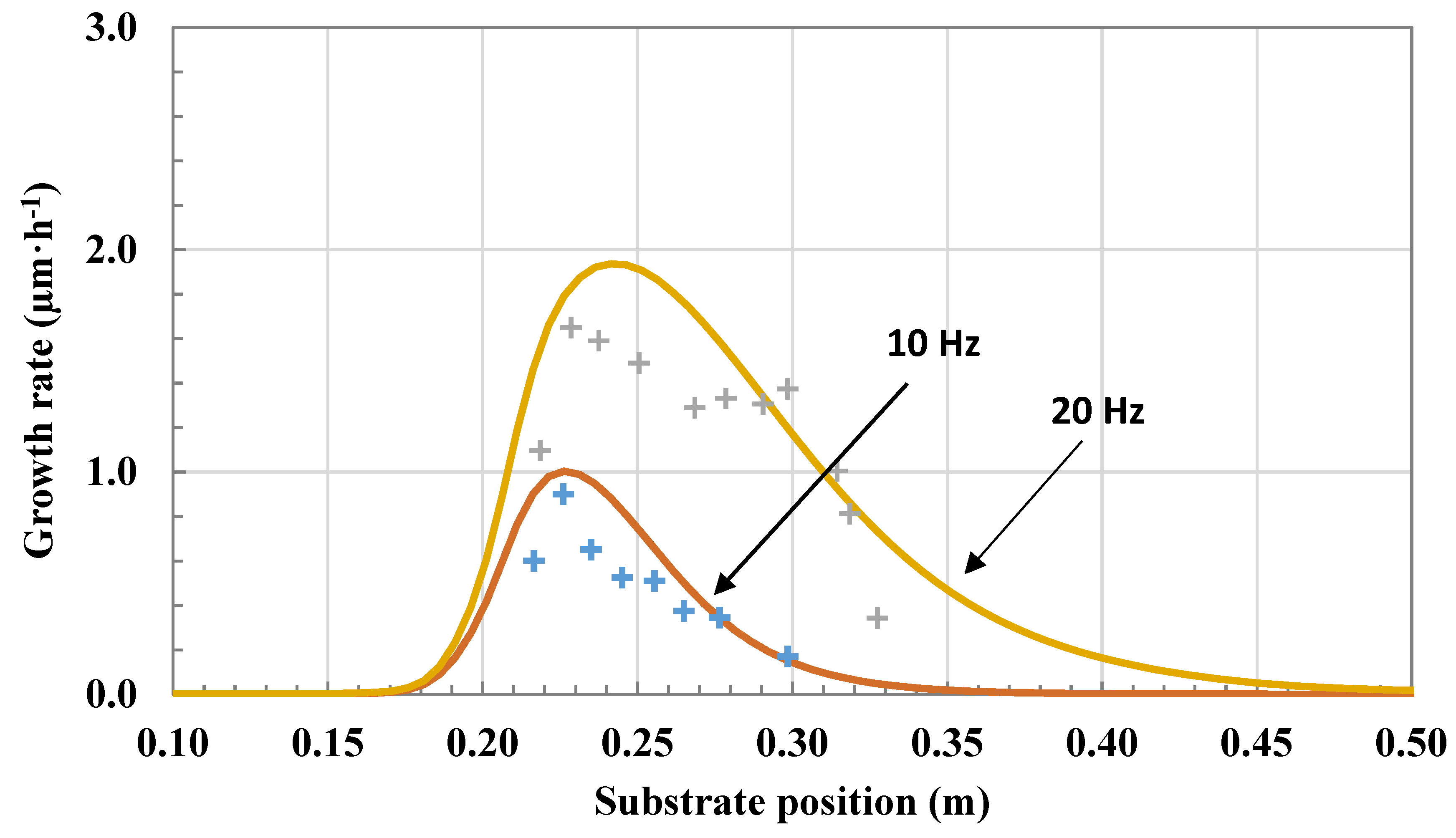
5. Results: Deposition in Long and Narrow Tubes

5.1. Preliminary Experiments in Short Tubes

The first step in modeling reactive mass transport was to fit the activation energy and the pre-exponential factor (Arrhenius law) of Reaction (1) (Table 1) with experiments. The first reactor used was a quartz reactor of 24 mm of diameter, 30 cm long containing a flat steel substrate 20 cm long (Figure 1b), and heated at 450, 500 and 550 °C. The flow rate of the carrier gas was 500 sccm and the flow rate of BBC was going from 0.8 to 3 sccm (Table 4). The fitting was first made with a 2-dimensionnal approximation of the reactor geometry then in 3D, which is representative of the geometry investigated. The temperature profile applied on the outer wall of the tube was the experimental values measured. Figure 5 shows the temperature profile in the 3D reactor. A cold finger at the entrance of the reactor comes from the injection of cold gas (200 °C) through a narrow area. This kind of situation is commonly found in large-scale CVD reactors [76,77].
The fit of kinetic constants was performed with six different configurations: two injection frequencies (10 and 20 Hz) and three deposition temperatures (450, 500 and 550 °C). The total pressure was kept constant at 7 × 10³ Pa. It was assumed that: (i) Reaction (1) (Table 1) is the limiting step of the deposition mechanism in agreement with the fact that the bonding energy for dissociating the first ligand is the largest; (ii) BBC is completely decomposed into MBC and C6H6 released in the gas phase (according to thermodynamic simulation in homogeneous gas phase); and (iii) surface reactions are not-limiting, have a sticking coefficient of 1 (Reaction (2)), and conserve the measured stoichiometry 2:1 for the Cr:C ratio (Reactions (3) and (4)). The best fit found for the activation energy and the pre-exponential factor is A = 1.2 × 10⁹ s−1 and E = 97 kJ·mol−1. The exponent β of temperature in Equation (7) is zero because Reaction (1) is monomolecular [78]. This activation energy is close to the experimental apparent activation energy estimated by Schuster et al. [5]. It is lower than the average value of the energy-bond breaking of the first ligand (160 kJ·mol−1) but, as is common for metalorganic compounds, the activation barrier for the overall decomposition of BBC is largely influenced by surface reactions and catalytic effects. The magnitude of the pre-exponential constant (frequency factor) is coherent with values found in the literature for monomolecular decomposition [78]. Table 5 summarizes the kinetic model with data that will be applied in further simulations.
The increase of the deposition rate at the entrance of the reactor is a competition between the cold finger and the decomposition rate of BBC (Figure 6). After 5 cm (on the steel plate 20 cm long), the effect of the depletion of reactive species leads to a rapid decrease of the deposition rate. This kind of profile is common in horizontal CVD reactors [34,40] and its optimization is a complex interaction of flow rate, precursor concentration, temperature and pressure fields and geometry design.

5.2. Chemical Vapor Deposition (CVD) Experiments inside Long and Narrow Tubes

The second step of this modeling approach was to study the deposition directly inside long and narrow tubes. The tubes studied were now directly used as reactors. They were 1 m long and have an inner diameter of 8 mm. After deposition, the tubes were cut in several slices to measure the thickness of the coating, its structure and morphology. The coating had an amorphous structure and a composition identical to that presented in the previous section and reported in detail elsewhere [65].
The models and databases developed and fitted for the previous short reactor gave results in good agreement with experiments performed in this new reactor geometry (Figure 7). A rapid depletion of the precursor downstream led to a poor uniformity along the inner wall of the tube. The conversion yield relative to the precursor was close to 60% at 450 °C and 40% at 400 °C as determined from the CrCx mass deposited. This decrease was representative of a thermally activated process. There was a very good agreement with calculated yields. The challenge was to significantly improve both the uniformity of the thickness profile on the internal walls of the tube and the average thickness, which should reach about 10 µm for applications. One issue was that CVD parameters often act in an antagonistic way to optimize these two requirements. Extensive simulation was performed to find the best operating conditions in a range of temperature, pressure and precursor composition suitable for industrialization of the process, i.e., low temperature, high thickness uniformity, as well as high growth rate and high conversion rate of the precursor to minimize the cost of the process. A good compromise to fulfil these requirements was calculated for the following conditions: 375 °C, 1.3 × 10² Pa, 4.33 sccm precursor flow rate, 100 sccm toluene flow rate and 500 sccm N2 flow rate.
A further improvement was simulated both to further optimize the thickness uniformity and to maximize the average thickness. It consisted of injecting the precursor successively and alternately at each end of the reactor tube with long sequences for several minutes to lower the residence time and increase the precursor availability. Under these conditions, the simulated thickness profiles shown in Figure 8 revealed that excellent thickness uniformity can be achieved at low pressure (1.3 × 10² Pa) and low temperatures (T ≤ 400 °C), but at the expense of a lower thickness. The relative variation between maximum and minimum thicknesses was lower than 10%. For higher values of pressure and temperature, a steep increase (or decrease) at the inlet (or outlet) side was found for this type of configuration.
It was not experimentally possible to perform experiments in the best simulated conditions. As a CVD experiment representative of this new concept of successive and alternating feeding at each end, a coating was made in two sequences of equivalent duration (3 h) where the injection of the precursor was made alternately at each end. The deposition temperature was 400 °C and the total pressure was 1.3 × 10³ Pa. The total thickness of the coating was the sum of these two sequences. Experimental data were compared to the simulation in Figure 9. Overall, there was a good agreement between the experiment and the simulation, and the uniformity of thickness was quite good for a relatively thick protective coating on the inner walls of tubes. The relative variation between the maximum and minimum thickness was about 40% for experimental data and 37% for the simulation along the isothermal zone of about 75 cm. With this novel protocol and these growth conditions, the minimum growth rate was about 2.1 µm/h and the conversion yield relative to the precursor was close to 60%, as determined from the CrCx mass deposited. As for results presented in Figure 7, there was a very good agreement with calculated yields. These results are very promising for the industrialization of such a process.

6. Conclusions

The results presented provide robust kinetic and multicomponent transport models capable of predicting amorphous CrCx growth at a range of low temperature (400 to 550 °C) and pressures (7 × 10² to 7 × 10³ Pa) well-suited to coat long and narrow metallic tubes. The development of the model is based on previously published data and additional experiments reported here. It allows the validation of the effects of precursor depletion along the inner walls of tubes as a function of the geometry, temperature, pressure and dilution of reactive species. The deposition of amorphous CrCx coatings from BBC is correctly described by the initial gas phase decomposition of BBC in MBC and benzene involving the bond breaking of the first Cr–C6H6 bond. It is followed by adsorption of MBC (and possibly a part of benzene) on surface sites leading to chromium and carbon deposition, and subsequently the formation of chromium carbide. It is also shown that the toluene, used as solvent for the liquid injection of BBC solution, does not participate to the reaction pathways.
Finally, it should be pointed out that the DLI-MOCVD process is capable of depositing rather uniform coatings inside long (1 m) and narrow (8 mm) tubes at low temperature to maintain the mechanical integrity of metal alloys. The peculiarities of this chemical system are that it does not form a coating below a temperature threshold of about 250 °C or solid byproducts condensed on the reactor wall in the low-temperature zones, and the composition and microstructure of the coatings are constant in the temperature range explored.
It follows that we have implemented an innovative concept of successive and alternating feeding of the tube at each end. This original method allows a good optimization of (i) the uniformity of thickness along the tube, (ii) its average growth rate, and (iii) the conversion yield of the precursor, which satisfies the main requirements for the industrialization of this process for inner-wall coating of tubes. CrCx coatings were successfully deposited by this process on the internal walls of fuel cladding tubes 1 m long and they exhibited an efficient inner protection to high-temperature oxidation in accidental conditions [79]. Although the models described here provide a sound basis for simulating practical deposition CVD reactors, important aspects of the chemistry merit further investigation. The measurements of BBC pyrolysis as well as the adsorption reactions are needed to assess more accurately the effects of temperature and pressure on deposition rates.

7. Patents

Method for depositing a coating by DLI-MOCVD with direct recycling of the precursor compound. F. Schuster, F. Maury, A. Michau, M. Pons, R. Boichot, F. Lomello; Patent No. WO/2017/103546, published on 22 June 2017.

Author Contributions

A.M. performed both the synthesis of the coatings (expected those of Figure 9 done by Y.G.) under the supervision of F.M. and F.S. and simulation of the process under the supervision of M.P., R.B. and I.N. M.P. wrote the manuscript, and all authors discussed the results and provided comments.

Funding

This research was funded by the “Investments for the Future” Program (No. ANR-10-LABEX-44-01) and by the Commissariat à l’Energie Atomique (CEA).

Acknowledgments

This research work was performed within the framework of the Centre of Excellence of Multifunctional Architectured Materials “CEMAM”.

Conflicts of Interest

The authors declare no conflict of interest.

References

  1. Briois, P.; Mercs, D.; Demange, V.; Banakh, O.; Sanchette, F.; Billard, A. Characterizations of CrN/a-CNx nanolayered coatings deposited by DC reactive magnetron sputtering of Cr and graphite targets. Vacuum 2011, 86, 206–209. [Google Scholar] [CrossRef]
  2. Bryskin, B.; Kostylev, A.; Pokrovskiy, Y.; Lumpov, A. CVD technology for preparing wear-resistive chromium carbide coatings of engine components. SAE Int. J. Mater. Manuf. 2014, 7, 630–632. [Google Scholar] [CrossRef]
  3. Castillejo, F.E.; Marulanda, D.M.; Olaya, J.J.; Alfonso, J.E. Wear and corrosion resistance of niobium–chromium carbide coatings on AISI D2 produced through TRD. Surf. Coat. Technol. 2014, 254, 104–111. [Google Scholar] [CrossRef] [Green Version]
  4. Maury, F. MOCVD of hard metallurgical coatings: Examples in the Cr–C–N system. Electrochim. Acta 2005, 50, 4525–4530. [Google Scholar] [CrossRef] [Green Version]
  5. Schuster, F.; Maury, F.; Nowak, J.F. Influence of organochromium precursor chemistry on the microstructure of MOCVD chromium carbide coatings. Surf. Coat. Technol. 1990, 43–44, 185–198. [Google Scholar] [CrossRef]
  6. Mugabi, J.A.; Eriksen, I.; Petrushina, I.; Christensen, E.; Bjerrum, N.J. Kinetic study of the chemical vapor deposition of tantalum in long narrow channels. Adv. Mater. Interfaces 2016, 3, 1500795. [Google Scholar] [CrossRef]
  7. Hinke, S.; StiJckel, S.; Marx, G. Characterization of BN-films deposited onto carbon fibres by a continuous CVD-process. Frenesius J. Anal. Chem. 1994, 349, 181. [Google Scholar] [CrossRef]
  8. Suzuki, M.; Tanaka, Y.; Inoue, Y.; Myamoto, N.; Sato, M.; Goda, K. Uniformization of boron nitride coating thickness by continuous chemical vapor deposition process for interphase of SiC/SiC composites. J. Ceram. Soc. Jpn. 2003, 111, 865–871. [Google Scholar] [CrossRef]
  9. Heffernan, W.J.; Ahmad, I.; Haskell, R.W. Continuous CVD process for coating filaments with tantalum carbide. In Proceedings of the 4th International Conference on Chemical Vapor Deposition, Boston, MA, USA, 7 October 1973; Wakefield, G.F., Ed.; Electrochemical Society: Princeton, NJ, USA, 1973; pp. 498–508. [Google Scholar]
  10. Kawamura, H.; Tachikawa, K. Preparation of the superconducting Nb3Ge tape by a continuous CVD process. Jpn. J. Appl. Phys. 1977, 16, 2037–2041. [Google Scholar] [CrossRef]
  11. Polsen, E.S.; McNerny, D.Q.; Viswanath, B.; Pattinson, S.W.; Hart, A.J. High-speed roll-to-roll manufacturing of graphene using a concentric tube CVD reactor. Sci. Rep. 2015, 5, 10257. [Google Scholar] [CrossRef] [PubMed] [Green Version]
  12. Liang, H.F.; Gordon, R.G. Atmospheric pressure chemical vapor deposition of transparent conducting films of fluorine doped zinc oxide and their application to amorphous silicon solar cells. J. Mater. Sci. 2007, 42, 6388–6399. [Google Scholar] [CrossRef]
  13. Schropp, R.E.I. Industrialization of hot wire chemical vapor deposition for thin film applications. Thin Solid Films 2015, 595, 272–283. [Google Scholar] [CrossRef]
  14. Casserly, T.; Boinapally, K.; Oppus, M.; Upadhyaya, D.; Boardman, B.; Tudhope, A. Investigation of DLC-Si film deposited inside a 304SS pipe using a novel hollow cathode plasma immersion ion processing method. In Proceedings of the 50th Annual Technical Conference Proceedings, Louisville, KY, USA, 28 April–3 May 2007; pp. 59–62. [Google Scholar]
  15. Besmann, T.; Matlin, W.; Stinton, D. Chemical vapor infiltration process modeling and optimization. MRS Proc. 1995, 410, 441–451. [Google Scholar] [CrossRef]
  16. Kwatera, A. Uniform thin chemically vapor-deposited layers of high density on the inner surfaces of tube-shaoed substrates. Thin Solid Films 1991, 204, 313–339. [Google Scholar] [CrossRef]
  17. Itoh, H.; Gonda, M.; Sugiyama, K. CVD of corrosion-resistant tin and tic films to inner wall of steel tubes. J. Met. Finish. Soc. Jpn. 1984, 35, 590–594. [Google Scholar] [CrossRef]
  18. Itoh, H.; Kato, K.; Sugiyama, K. Chemical vapour deposition of tin film to the inner walls of long steel tubes. J. Mater. Sci. 1986, 21, 751–756. [Google Scholar] [CrossRef]
  19. Drieux, P.; Chollon, G.; Jacques, S.; Allemand, A.; Cavagnat, D.; Buffeteau, T. Experimental study of the chemical vapor deposition from CH3SiHCl2/H2: Application to the synthesis of monolithic sic tubes. Surf. Coat. Technol. 2013, 230, 137–144. [Google Scholar] [CrossRef]
  20. Duguet, T.; Vahlas, C.; Ledru, Y. Method and Device for the Formation of a Continuous Layer on the Inner and Outer Surfaces of a Hollow Part and Part Thus Produced. Patent WO 201,410,218,8A1, 3 July 2014. [Google Scholar]
  21. Hertz, D.; Audisio, S.; Defoort, F.; Idriss, H. Method of Obtaining an Insulating Coating of Chromium Oxide between the Pellets and the Cladding of a Nuclear Fuel Element and Nuclear Fuel Element Having such an Insulating Coating. Patent EP 040,969,3A1, 23 January 1991. [Google Scholar]
  22. Poirier, L.; Wang, Y.B.; Ducarroir, M.; Teyssandier, F. Ceramic coating of metal tube inner surfaces by MOCVD. In Proceedings of the 14th International Conference on Chemical Vapor Deposition, Paris, France, 5–9 September 1997; Allendorf, M.D., Bernard, C., Eds.; Electrochemical Society: Pennington, NJ, USA, 1997; Volume 25, pp. 425–432. [Google Scholar]
  23. Xiong, Y.Q.; Dong, M.J.; Li, K.; Wang, J.Z.; Ren, N. Model for atomic layer deposition on inner wall of rectangular pipes with large aspect ratio. In Proceedings of the Eighth International Conference on Thin Film Physics and Applications, Shanghai, China, 20–23 September 2013; Chu, J., Wang, C., Eds.; SPIE: Bellingham, WA, USA, 2013; p. UNSP 90680C. [Google Scholar]
  24. Ives, R.L.; Oldham, C.J.; Daubert, J.S.; Gremaud, A.P.; Collins, G.; Marsden, D.; Bui, T.; Fusco, M.A.; Mitsdarffer, B.; Parsons, G.N. Corrosion mitigation coatings for RF sources and components. IEEE Trans. Electron Devices 2018, 65, 2385–2392. [Google Scholar] [CrossRef]
  25. Karwa, M.; Iqbal, Z.; Mitra, S. Scaled-up self-assembly of carbon nanotubes inside long stainless steel tubing. Carbon 2006, 44, 1235–1242. [Google Scholar] [CrossRef]
  26. Clark, T.J.; Banash, M.A.; Cruse, R.W.; Mininni, R.M.; Rohman, S.J. Model for chemical vapor deposition of nanostructured ceramics inside tubes under high temperature laminar flow conditions. Nanostruct. Mater. 1994, 4, 723–735. [Google Scholar] [CrossRef]
  27. Johnson, C.E.; Crouthamel, C.E. Nuclear Reactor Fuel Element. U.S. Patent 42,292,601,980, 21 October 1980. [Google Scholar]
  28. Field, A.L. Process for Coating the Internal Surface of a Metal Tube with a Neutron Absorber. Patent EP 020,456,5A2, 10 December 1986. [Google Scholar]
  29. Douard, A.; Bernard, C.; Maury, F. Thermodynamic simulation of atmospheric DLI-CVD processes for the growth of chromium-based hard coatings using bis(benzene)chromium as molecular source. Surf. Coat. Technol. 2008, 203, 516–520. [Google Scholar] [CrossRef] [Green Version]
  30. Allendorf, M.D.; van Mol, A.M.B. Gas-phase thermochemistry and mechanism of organometallic tin oxide CVD precursors. Top. Organomet. Chem. 2005, 9, 1–48. [Google Scholar]
  31. Chae, Y.; Houf, W.G.; McDaniel, A.H.; Allendorf, M.D. Models for the chemical vapor deposition of tin oxide from monobutyltintrichloride. J. Electrochem. Soc. 2006, 153, C309–C317. [Google Scholar] [CrossRef]
  32. Dauelsberg, M.; Brien, D.; Rauf, H.; Reiher, F.; Baumgartl, J.; Häberlen, O.; Segal, A.S.; Lobanova, A.V.; Yakovlev, E.V.; Talalaev, R.A. On mechanisms governing ALN and ALGaN growth rate and composition in large substrate size planetary MOVPE reactors. J. Cryst. Growth 2014, 393, 103–107. [Google Scholar] [CrossRef]
  33. Dauelsberg, M.; Kadinski, L.; Makarov, Y.N.; Bergunde, T.; Strauch, G.; Weyers, M. Modeling and experimental verification of transport and deposition behavior during MOVPE of Ga1-xinxP in the planetary reactor. J. Cryst. Growth 2000, 208, 85–92. [Google Scholar] [CrossRef]
  34. Endres, D.; Mazumder, S. Numerical investigation of pulsed chemical vapor deposition of aluminum nitride to reduce particle formation. J. Cryst. Growth 2011, 335, 42–50. [Google Scholar] [CrossRef]
  35. Etchepare, P.L.; Vergnes, H.; Samélor, D.; Sadowski, D.; Caussat, B.; Vahlas, C. Modeling a MOCVD process to apply alumina films on the inner surface of bottles. Surf. Coat. Technol. 2015, 275, 167–175. [Google Scholar] [CrossRef] [Green Version]
  36. Han, X.-F.; Lee, J.-H.; Lee, Y.-J.; Song, J.-H.; Yi, K.-W. Numerical analysis on the origin of thickness unevenness and formation of pits at GaN thin film grown by HVPE. J. Cryst. Growth 2016, 450, 66–73. [Google Scholar] [CrossRef]
  37. Inagaki, Y.; Kozawa, T. Chemical reaction pathways for MOVPE growth of aluminum nitride. ECS J. Solid State Sci. Technol. 2015, 5, P73–P75. [Google Scholar] [CrossRef]
  38. Li, M.; Sopko, J.F.; McCamy, J.W. Computational fluid dynamic modeling of tin oxide deposition in an impinging chemical vapor deposition reactor. Thin Solid Films 2006, 515, 1400–1410. [Google Scholar] [CrossRef]
  39. Manin, M.; Thollon, S.; Emieux, F.; Berthome, G.; Pons, M.; Guillon, H. Deposition of MgO thin film by liquid pulsed injection MOCVD. Surf. Coat. Technol. 2005, 200, 1424–1429. [Google Scholar] [CrossRef]
  40. Mazumder, S.; Lowry, S.A. The importance of predicting rate-limited growth for accurate modeling of commercial MOCVD reactors. J. Cryst. Growth 2001, 224, 165–174. [Google Scholar] [CrossRef]
  41. Mihopoulos, T.G.; Gupta, V.; Jensen, K.F. A reaction-transport model for AlGaN MOVPE growth. J. Cryst. Growth 1998, 195, 733–739. [Google Scholar] [CrossRef]
  42. Momose, T.; Kamiya, T.; Suzuki, Y.; Ravasio, S.; Cavallotti, C.; Sugiyama, M.; Shimogaki, Y. Kinetic analysis of GaN-MOVPE via thickness profiles in the gas flow direction with systematically varied growth conditions. ECS J. Solid State Sci. Technol. 2016, 5, P164–P171. [Google Scholar] [CrossRef]
  43. Nieto, J.P.; Jeannerot, L.; Caussat, B. Modelling of an industrial moving belt chemical vapour deposition reactor forming SiO2 films. Chem. Eng. Sci. 2005, 60, 5331–5340. [Google Scholar] [CrossRef] [Green Version]
  44. Theodoropoulos, C.; Mountziaris, T.J.; Moffat, H.K.; Han, J. Design of gas inlets for the growth of gallium nitride by metalorganic vapor phase epitaxy. J. Cryst. Growth 2000, 217, 65–81. [Google Scholar] [CrossRef]
  45. Vorob’ev, A.N.; Archakov, I.Y.; Bord, O.V.; Smirnov, S.A.; Karpov, S.Y.; Makarov, Y.N.; Reinhold, M.; Schumacher, M.; Heuken, M. Advanced model for the simulation of BST-film growth with MOCVD. Synth. Met. 2003, 138, 145–151. [Google Scholar] [CrossRef]
  46. Xenidou, T.C.; Prud’homme, N.; Vahlas, C.; Markatos, N.C.; Boudouvis, A.G. Reaction and transport interplay in al MOCVD investigated through experiments and computational fluid dynamic analysis. J. Electrochem. Soc. 2010, 157, D633–D641. [Google Scholar] [CrossRef] [Green Version]
  47. Douard, A.; Maury, F. Nanocrystalline chromium-based coatings deposited by DLI-MOCVD under atmospheric pressure from Cr(CO)6. Surf. Coat. Technol. 2006, 200, 6267–6271. [Google Scholar] [CrossRef] [Green Version]
  48. Bird, R.B.; Stewart, W.E.; Lightfoot, E.N. Transport Phenomena, 2nd ed.; John Wiley & Sons Inc.: New York, NY, USA, 2007. [Google Scholar]
  49. Kee, R.J.; Dixon-Lewis, G.; Warnatz, J.; Coltrin, M.E.; Miller, J.A.; Moffat, H.K. A Fortran Computer Code Package for the Evaluation of Gas-Phase, Multicomponent Transport Properties; SAND86-8246B; Sandia National Laboratories: Albuquerque, NM, USA, 1986.
  50. Brioukov, M.G.; Park, J.; Lin, M.C. Kinetic modeling of benzene decomposition near 1000 k: The effects of toluene impurity. Int. J. Chem. Kinet. 1999, 31, 577–582. [Google Scholar] [CrossRef]
  51. Maury, F.; Vahlas, C.; Abisset, S.; Gueroudji, L. Low temperature metallorganic chemical vapor deposition routes to chromium metal thin films using bis(benzene)chromium. J. Electrochem. Soc. 1999, 146, 3716–3723. [Google Scholar] [CrossRef]
  52. Devyatykh, G.G.; Larin, N.V.; Gaivoronskii, P.E. Mass spectrum of bis(benzene)chromium and the appearance potentials of ions. J. Gen. Chem. USSR 1969, 39, 1786–1787. [Google Scholar]
  53. Sahnoun, R.; Mijoule, C. Density functional study of metal–arene compounds: Mono(benzene)chromium, bis(benzene)chromium and their cations. J. Phys. Chem. A 2001, 105, 6176–6181. [Google Scholar] [CrossRef]
  54. Devi, A.; Schmid, R.; Müller, J.; Fischer, R.A. Materials chemistry of group 13 nitrides. Top. Organomet. Chem. 2005, 9, 49–80. [Google Scholar]
  55. Koel, B.E.; Crowell, J.E.; Bent, B.E.; Mate, C.M.; Somorjai, G.A. Thermal decomposition of benzene on the rhodium(111) crystal surface. J. Phys. Chem. 1986, 90, 2949–2956. [Google Scholar] [CrossRef]
  56. Kurikawa, T.; Takeda, H.; Hirano, M.; Judai, K.; Arita, T.; Nagao, S.; Nakajima, A.; Kaya, K. Electronic properties of organometallic metal−benzene complexes [Mn(benzene)m (M = Sc–Cu)]. Organometallics 1999, 18, 1430–1438. [Google Scholar] [CrossRef]
  57. Timms, P.L. Transition metal vapors in chemical synthesis. The direct preparation of dibenzene chromium as an undergraduate experiment. J. Chem. Educ. 1972, 49, 782–784. [Google Scholar] [CrossRef]
  58. Blass, P.M.; Akhter, S.; Seymour, C.M.; Lagowski, J.J.; White, J.M. The adsorption and decomposition of BIS(Benzene)chromium on Ni(100). Surf. Sci. 1989, 217, 85–102. [Google Scholar] [CrossRef]
  59. Lamanna, W.M. Metal vapor synthesis of a novel triple-decker sandwich complex: (.Eta.6-mesitylene)2(.Mu.-.Eta.6:.Eta.6-mesitylene)Cr2. J. Am. Chem. Soc. 1986, 108, 2096–2097. [Google Scholar] [CrossRef]
  60. Liu, A.C.; Friend, C.M. The structure and reactivity of chemisorbed aromatics: Spectroscopic studies of benzene on Mo(110). J. Chem. Phys. 1988, 89, 4396–4405. [Google Scholar] [CrossRef]
  61. Maury, F.; Douard, A.; Delclos, S.; Samelor, D.; Tendero, C. Multilayer chromium based coatings grown by atmospheric pressure direct liquid injection CVD. Surf. Coat. Technol. 2009, 204, 983–987. [Google Scholar] [CrossRef] [Green Version]
  62. Maury, F.; Gueroudji, L.; Vahlas, C. Selection of metalorganic precursors for MOCVD of metallurgical coatings: Application to Cr-based coatings. Surf. Coat. Technol. 1996, 86–87, 316–324. [Google Scholar] [CrossRef]
  63. Vahlas, C.; Maury, F.; Gueroudji, L. A thermodynamic approach to the CVD of chromium and of chromium carbides starting from Cr(C6H6)2. Chem. Vapor Depos. 1998, 4, 69–76. [Google Scholar] [CrossRef]
  64. Maury, F.; Oquab, D.; Manse, J.C.; Morancho, R.; Nowak, J.F.; Gauthier, J.P. Structural characterization of chromium carbide coatings deposited at low temperature by low pressure chemical vapour decomposition using dicumene chromium. Surf. Coat. Technol. 1990, 41, 51–61. [Google Scholar] [CrossRef]
  65. Michau, A.; Maury, F.; Schuster, F.; Boichot, R.; Pons, M.; Monsifrot, E. Chromium carbide growth at low temperature by a highly efficient DLI-MOCVD process in effluent recycling mode. Surf. Coat. Technol. 2017, 332, 96–104. [Google Scholar] [CrossRef] [Green Version]
  66. Maury, F.; Ossola, F. Evaluation of tetra-alkylchromium precursors for organometallic chemical vapour deposition I. Films grown using Cr[CH2C(CH3)3]4. Thin Solid Films 1992, 207, 82–89. [Google Scholar] [CrossRef]
  67. Chase, M.W.J. NIST-JANAF Thermochemical Tables, 4th ed.; Journal of Physical and Chemical Reference Data Monographs; American Institute of Physics: College Park, MD, USA, 1998; pp. 1–1951. [Google Scholar]
  68. Schäfer, L.; Southern, J.F. Some additional evidence for the sixfold symmetry of benzene in dibenzenechromium in the vapor phase. J. Organomet. Chem. 1970, 24, C13–C15. [Google Scholar] [CrossRef]
  69. Ngai, L.H.; Stafford, F.E.; Schäfer, L. The symmetry of gaseous dibenzenechromium. J. Am. Chem. Soc. 1969, 91, 48–49. [Google Scholar] [CrossRef]
  70. Hirschefelder, J.O. Simple method for calculating moments of inertia. J. Chem. Phys. 1940, 8, 431–432. [Google Scholar] [CrossRef]
  71. Haaland, A. The molecular structure of gaseous dibenzene chromium (C6H6)2Cr. Acta Chem. Scand. 1965, 19, 41–46. [Google Scholar] [CrossRef]
  72. Andrews, J.T.S.; Westrum, E.F.; Bjerrum, N. Heat capacity and vapor pressure of crystalline bis(benzene)chromium. Third-law entropy comparison and thermodynamic evidence concerning the structure of bis(benzene)chromium. J. Organomet. Chem. 1969, 17, 293–302. [Google Scholar] [CrossRef]
  73. Kee, R.J.; Rupley, F.M.; Miller, J.A. The Chemkin Thermodynamic Data Base; SAND87-8215B; Sandia National Laboratories: Albuquerque, NM, USA, 1990.
  74. McBride, B.J.; Gordon, S.; Reno, M.A. Coefficients for Calculating Thermodynamic and Transport Properties of Individual Species; NASA Techinical Memorandum 4513; NASA: Washington, DC, USA, 1993.
  75. Svehla, R.A. Estimated Viscosities and Thermal Conductivities of Gases at High Temperatures; Technical Report R-132; NASA: Washington, DC, USA, 1962.
  76. Bouteville, A. Numerical simulation applied to chemical vapor deposition process. Rapid thermal CVD and spray CVD. J. Optoelectron. Adv. Mater. 2005, 7, 599–606. [Google Scholar]
  77. Li, Z.; Zhang, J.; Li, J.; Jiang, H.; Fu, X.; Han, Y.; Xia, Y.; Huang, Y.; Yin, J.; Zhang, L.; et al. Modeling and simulation of a novel susceptor composed of two materials in MOVPE reactor. J. Cryst. Growth 2014, 402, 175–178. [Google Scholar] [CrossRef]
  78. Benson, S.W.; O’Neal, H.E. Kinetic Data on Gas Phase Unimolecular Reactions; NSRDS-NBS21, National Standard Reference Data Series; US Department of Commerce: Washington, DC, USA, 1970.
  79. Michau, A.; Maury, F.; Schuster, F.; Lomello, F.; Brachet, J.C.; Rouesne, E.; Saux, M.L.; Boichot, R.; Pons, M. High-temperature oxidation resistance of chromium-based coatings deposited by dli-MOCVD for enhanced protection of the inner surface of long tubes. Surf. Coat. Technol. 2018, in press. [Google Scholar]
Figure 1. (a) Schematic representation of the direct liquid injection metal-organic chemical vapor deposition reactor (direct-pulsed liquid injection–metalorganic chemical vapor deposition (DLI–MOCVD)); the dimensions of the reactor tube are from 0.3 to 1 m; the diameter of the tube is from 8 to 24 mm. (b) Schematic representation of the quartz reactor of 24 mm in diameter, 30 cm long, containing a flat substrate of 20 cm.
Coatings 08 00220 g001
Figure 2. Typical cross section of CrxCy coating grown on silicon substrate placed on the substrate holder inside a quartz tube 30 cm long, 24 mm internal diameter (ID) (450 °C, 7 × 10³ Pa, 500 sccm N2, 250 sccm C7H8, 0.8 sccm bis(benzene)chromium (BBC)).
Coatings 08 00220 g002
Figure 3. Evolution of the growth rate along the 20 cm substrate placed in the tube (30 mm in diameter) for two different pressures: Same experimental conditions as in Figure 2 for temperature and N2 flow rate; BBC flow rate is 0.8 and 3 sccm (0.16% and 0.6%).
Coatings 08 00220 g003
Figure 4. Transmittance spectrum of a bare quartz sample compared to C-coated quartz samples after 1 h flow of toluene at 600, 750 and 800 °C showing an increase of the absorption in the visible range resulting from the growth of the C thin film.
Coatings 08 00220 g004
Figure 5. Temperature field in the central XY slice of the tubular reactor schematized in Figure 1b (Table 4, Run 1).
Coatings 08 00220 g005
Figure 6. Comparison of calculated () and measured (+) growth rate of chromium carbide on the 20 cm substrate in the conditions of Table 4 (Run 1 and 2).
Coatings 08 00220 g006
Figure 7. Comparison of calculated () and measured (+) growth rate of chromium carbide along the 1 m reactor walls (T = 400 and 450 °C, P = 7 × 10² Pa, precursor flow rate 4.4 sccm, N2 flow rate 500 sccm).
Coatings 08 00220 g007
Figure 8. Calculated growth rate of chromium carbide along the 1 m reactor walls with alternate injection (T = 450, 400 and 375 °C).
Coatings 08 00220 g008
Figure 9. Calculated () and experimental (●) growth rate of CrCx coatings along the inner wall of the tube reactor 1 m long with the injection of the precursor successively and alternately at each end (T = 400 °C; P = 1.3 × 10³ Pa; duration = 2 × 3 h; 500 sccm N2; injection of 0.5 g min−1 of precursor solution in toluene containing 10.3 wt. % of bis(ethylbenzene)chromium (BEBC)).
Coatings 08 00220 g009
Table 1. Reaction pathways. Cr(s) is a chromium site, Cr(b) and C(b) are bulk chromium and carbon respectively, and C6H6(s) is adsorbed benzene.
No.Reactions
(1)Cr(C6H6)2(g) → CrC6H6(g) + C6H6(g)
(2)CrC6H6(g) + Cr(s) → Cr(b) + C6H6(s) + Cr(s)
(3)C6H6(s) → 6C(b) + 3H2(g)
(4)C6H6(s) → C6H6(g)
(5)Cr(C6H6)2(g) + Cr(s) → Cr(b) + CrC6H6(s) + C6H6(s)
(6)Cr(C6H6)(s) + Cr(s) → Cr(b) + C6H6(s) + Cr(s)
Table 2. Thermodynamic data for BBC(g) and mono(benzene)chromium (MBC(g)); T is the temperature, R the universal gas phase constant, H the enthalpy, S the entropy and C p the specific heat.
GasTemperature (K)a1a2a3a4a5a6a7
BBC298–660−1.207 × 1011.460 × 10−1−1.248 × 10−46.843 × 10−8−2.999 × 10−112.805 × 1044.661 × 101
BBC660–10007.1337.445 × 10−2−2.730 × 10−51.095 × 10−17−6.776 × 10−212.410 × 10⁴−4.700 × 101
MBC298–770−8.2919.563 × 10−2−1.177 × 10−49.428 × 10−8−3.716 × 10−112.993 × 1043.792 × 101
MBC770–10002.9954.138 × 10−2−1.576 × 10⁻⁵−2.168 × 10−190.0002.809 × 104−1.450 × 101
C p ( T ) R = a 1 + a 2 T + a 3 T 2 + a 4 T 3 + a 5 T 4
H ( T ) R T = a 1 + a 2 2 T + a 3 3 T 2 + a 4 4 T 3 + a 5 5 T 4 + a 6 T
S ( T ) R = a 1 ln ( T ) + a 2 T + a 3 2 T 2 + a 4 3 T 3 + a 5 4 T 4 + a 7
Table 3. Lennard-Jones parameters for species used in the simulation.
Gas SpeciesCollision Diameter (Å)Potential (K)
BBC6.98519.2
MBC6.03462.4
C6H65.35412.3
C2H24.1209
C7H85.92410
H22.9238
N23.871.4
Table 4. Operating conditions used for modeling.
Experiment (Run)Temperature (°C)BBC Flow (sccm)Toluene Flow (sccm)N2 Flow (sccm)P (Pa)Injection Frequency (Hz)
14500.82205007 × 10310
245036305007 × 10320
35000.92505007 × 10310
45003.26805007 × 10320
55500.82305007 × 10310
65503.67605007 × 10320
Table 5. Kinetic data in the form defined by Equations (7) and (8).
ReactionA (s−1)Ea/R (K)SC
(1) Cr(C6H6)2(g) → CrC6H6(g) + C6H6(g)1.2 × 10911,700
(2) CrC6H6(g) + Cr(s) → Cr(b) + C6H6(s) 1
(3) C6H6(s) → 6C(b) + 3H2(g) fitted
(4) C6H6(s) → C6H6(g) fitted

