Raman Spectroscopy for Reliability Assessment of Multilayered AlCrN Coating in Tribo-Corrosive Conditions


1
Department of Mechanical and Industrial Engineering, Tallinn University of Technology, 12616 Tallinn, Estonia
2
Department of Materials and Environmental Technology, Tallinn University of Technology, 12616 Tallinn, Estonia
3
European Space Agency ESA-ESTEC, Materials and Processes Section, 2201 Noordwijk, The Netherlands
*
Author to whom correspondence should be addressed.
Coatings 2018, 8(7), 229; https://doi.org/10.3390/coatings8070229
Submission received: 18 May 2018
/
Revised: 11 June 2018
/
Accepted: 20 June 2018
/
Published: 26 June 2018
(This article belongs to the Special Issue Coatings Tribology)
Abstract
:In this study, a multilayered AlCrN coating has been employed as a protective layer for steel used in tribo-corrosive conditions. The coating was deposited by a lateral rotating cathode arc PVD technology on a AISI 316L stainless steel substrate. A ratio of Al/(Al + Cr) was varied from 0.5 up to 0.6 in the AlCrN layer located above Cr adhesion and gradient CrN interlayers. A Raman spectroscopy and potentiodynamic polarization scan were used to determine the resistance in tribo-corrosive (3.5 wt % NaCl) conditions. Correlation between sliding contact surface chemistry and measured tribological properties of material was supported with static corrosion experiments. The corrosion mechanisms responsible for surface degradation are reported.
1. Introduction
One of the problems in the industrial application of moving bodies concerns the mechanical interaction between sliding surfaces and surface chemical reactions or corrosion occurring in reactive environments such as an aqueous media. A simplified description of tribo-corrosion phenomenon is related to a material transformation process due to simultaneous corrosion and wear taking place at contacting surfaces in relative motion [1].
Corrosion resistance is one of the most important factors to be taken into consideration for manufacturing metal products, as the formation of rust can have a devastating impact on the performance. Protection of the metal surfaces with physical vapour deposited coatings is a widely used technique. It could be assumed that such treatment will be even more relevant in future due to boosting of 3D metal printing technologies (additive manufacturing) [2]. Reliable lifetime prediction for a component used in an aqueous corrosive environment requires the identification of corrosion failure modes. Such failure modes can be pitting (if halide ions are present), stress-corrosion caused cracking by hydrogen embrittlement and corrosion fatigue [3].
The effect of mechanical stimulation on chemical degradation of materials and, vice-versa, the influence of corrosion on the mechanical response of contacting materials are of great concern for modern technologies including power generation, marine, and offshore industries. Materials properties, surface transformations, and electrochemical reactions are important aspects to be considered during materials selection for any specific application as cumulative effects of mechanical and chemical factors can result in unexpected behaviour and catastrophic loss of integrity. However, the chemo-mechanical mechanisms of tribo-corrosion are not yet well-understood and are extremely complex as they involve a great number of parameters [1,4,5,6]. A realistic evaluation of materials reliability is further hindered by the experimental difficulties in process characterization. Moreover, the overall rate of material degradation is rarely the sum of just corrosion and wear but is influenced by multiple reactions and transformations that take place during tribo-corrosive interactions. Therefore, an attempt to use Raman spectroscopy as a non-destructive and relatively fast method for understanding processes of tribo-corrosion is of potential benefit [7].
Nowadays the use of protective coatings containing carbon, oxygen, or nitrogen (e.g., carbides, nitrides, carbonitrides, or oxynitrides) is considered to be a practical method for improvement of the performance of metals and alloys [8,9,10]. Transition metal nitrides ensure the high hardness, acceptable wear, and corrosion resistance when applied as physical vapour deposited (PVD) coatings to enable application under aggressive environments [11,12]. Dominating phase transition changes from cubic to hexagonal have been found in AlxCr1−xN by increasing x up to about 0.71 [13]; however, this value has not been strictly defined.
In many cases, a ceramic coating cannot be applied directly to an SS substrate due to insufficient bonding efficiency. As the result of this, intensive delamination of a coating can take place. It is especially harmful, if emission of Cr containing particles takes place that can oxidize into a toxic and cancerogenic Cr(VI) [14]. Accordingly, an adhesive interlayer with as possible similar lattice parameters can be applied. In such situation, a process of inter-diffusion between coating and substrate may occur. Cohesive energy densities or solubility parameters should match according to thermodynamic considerations to attain good bonding between a substrate and an adhesive layer [15]. A combination of Fe and Cr satisfy these conditions as both have bcc structures. It is well known that specific interactions between the components enable blending the miscible materials [16]. The ideal work of adhesion properties of the Cr(100)/Fe(100) and Cr(110)/Fe(110) abrupt interfaces has been predicted to be about 5.4 J·m−2. Endothermic intermixing occurs at the interface of Cr film and Fe substrate, exhibiting a very strong adhesion caused by strong covalent bonding in addition to metallic cohesion and nearly lack of strain [14]. Intermixing causes a favourable concentration gradient transition zones distinguished by thermodynamic compatibility of a substrate-coating system [17].
Herein, the tribo-corrosive processes occurring at multilayered AlCrN PVD coatings deposited over stainless steel (SS) substrate demonstrating an applicability of Raman spectroscopy for determination of corrosion products and possible coating failures under static and tribologically initiated conditions is reported.
2. Materials and Methods
2.1. Materials
Austenitic conventional (produced by casting and rolling) SS AISI 316L (UNS S31603, dimension: 25 mm × 15 mm × 5 mm) supplied by Outokumpu (Helsinki, Finland) was used as the substrate material for the compositions described. Selected Fe based SS typically contains Cr (17.2 wt %) C (0.02 wt %), Ni (10.1 wt %) and Mo (2.1 wt %) according to properties provided by the producer. A small concentration of several other elements like Si, P, S, Mn, and N can be detected during elemental analysis.
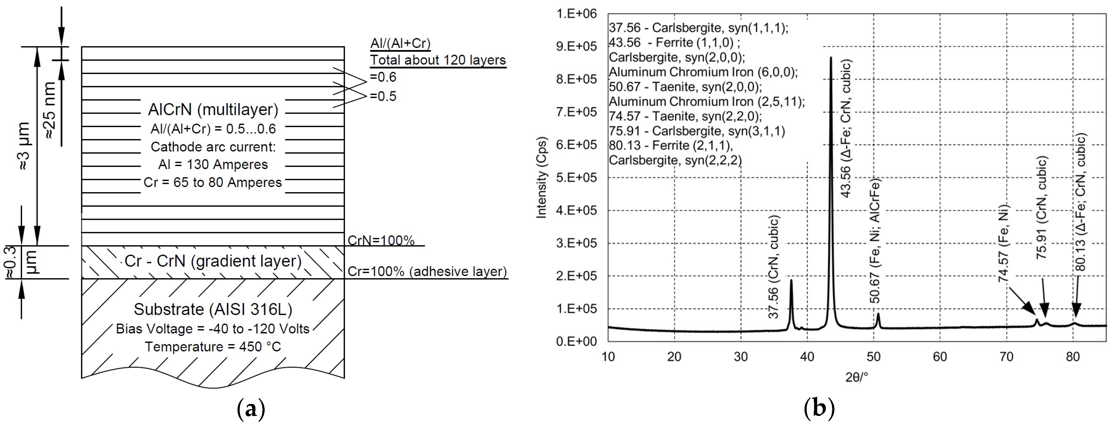
An arithmetical mean roughness of the substrates Ra ≤ 0.02 µm was reached using a Phoenix 4000 (Buehler, Lake Bluff, IL, USA) polishing system by applying SiC papers (Buehler) down to grade P4000 (MicroCut S, Buehler). Substrates were cleaned with an isopropanol for 50 min in an ultrasonic bath and then sputter-cleaned in a chamber with argon plasma with the bias voltage of 850 V at 425 °C for 1 h. Chromium adhesive and gradient CrN interlayers were used in order to provide sufficient adhesion of the AlCrN coating to the substrate. The structure of alternating layers with an Al/(Al + Cr) ratio of 0.6 and 0.5 was produced by varying the Cr cathode arc current, [5]. The adhesion of the coating to the substrate was characterised as class 1 according to VDI 3198. The thickness of the AlCrN coating was established as 3 μm and the thickness of the Cr/CrN interlayer was about 0.3 μm (Kalotest method by BAQ GmbH KaloMAX ball cratering device according to EN1071-2007). The deposition temperature for the substrate was 450 °C. The schematic representation of the coating described is given in Figure 1a. A dominating cubic CrN phase was confirmed by XRD in the structure of the AlCrN PVD coating after deposition, as demonstrated in Figure 1b (minerals with similar XRD signals are indicated). The main properties of the coating are listed in Table 1.
Counter-body balls of yttria-stabilized tetragonal zirconia (YSZ, 95% ZrO2, 5% Y2O3, Tosoh/Nikkato, Tokyo, Japan) were used in this research. The main properties of the balls are listed in Table 1.
2.2. Characterization of Materials
Surface morphology was studied using a scanning electron microscope (SEM) Hitachi TM1000 (Tokyo, Japan) equipped with an energy-dispersive X-ray source (EDS).
Raman spectral analysis was performed at room temperature using a high resolution micro-Raman spectrometer (Horiba Jobin Yvon HR800, Kyoto, Japan) equipped with a multichannel charge-coupled device (CCD) detection system. The device was set in the backscattering configuration. An Nd-YAG induced laser (λ = 532 nm) with a spot size of 10 μm in diameter was used for excitation. The results were obtained with laser beam powers of 2.8 mW (factor of filter was 0.0912) and 15.8 mW (factor of filter was 0.5147). The laser beam power was kept unchanged for all test materials (including transferred material). Crystal phases of the AlCrN PVD coating were detected by X-ray diffractometer (XRD) Rigaku Ultima IV (Tokyo, Japan). Obtained results were compared with measurement results from X-ray diffractometer Bruker D5005 AXS (Billerica, MA, US). A monochromatic CuKα radiation in 2θ scan mode was applied. Commercially available database ICDD-PDF-4+2016 was used for the identifications of crystal phases.
2.3. Evaluation of Coating Reliability
Selected laboratory-scale experimental methods and approaches for improvement of reliability of the AlCrN PVD coating on the steel substrate for use in aggressive environments are listed in Table 2. The selection was done according to applicability for determination of coating reliability under static and tribologically influenced conditions. Visual observation, imaging techniques (optical, SEM, 2D or 3D profiling), ball cratering, adhesion or scratch testing are mainly suitable for preliminary estimation of properties and prediction of performance while electrochemical or tribo-corrosive tests (accompanied with electrochemical measurements) provide the possibility for tracking the performance of materials In-Situ. To great extent, only Raman spectroscopy can assist in an evaluation of the composition of a thin layer formed during tribological testing of material.
2.3.1. Potentiodynamic Polarization Test
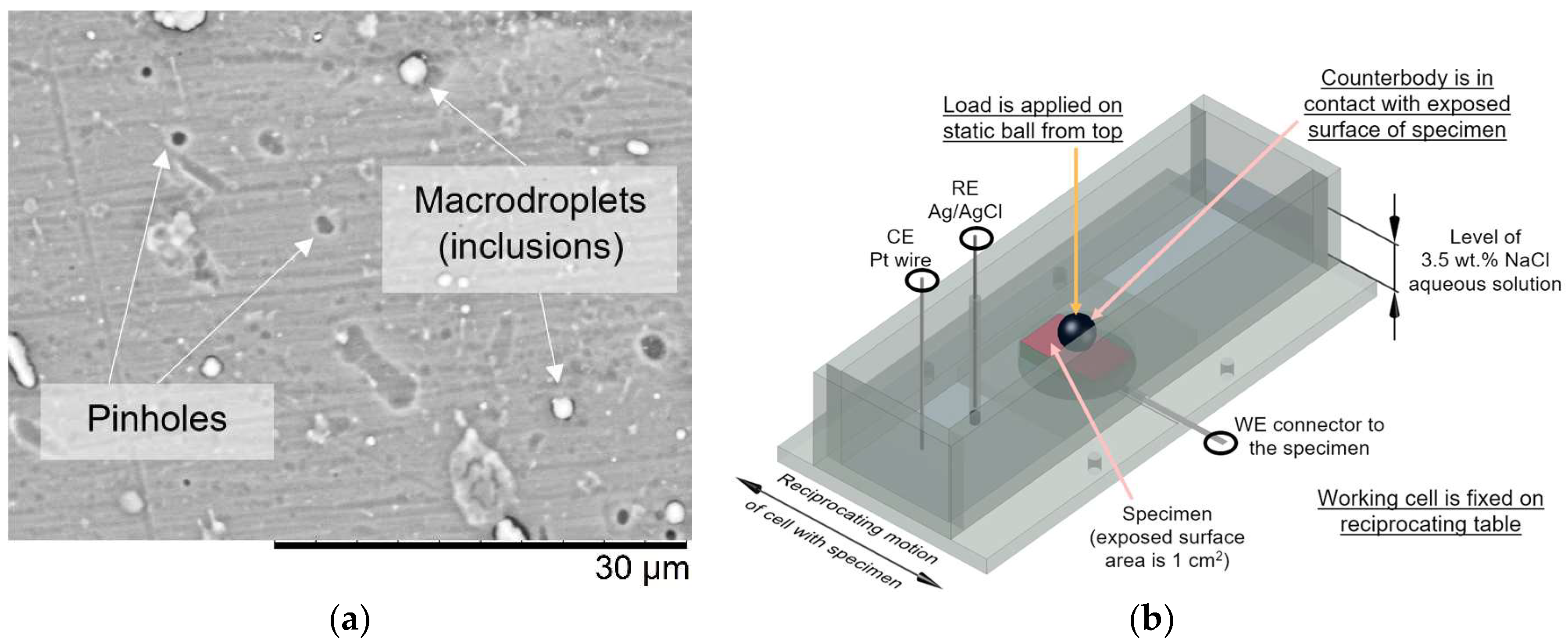
The typical three-electrode cell was used with the Pt counter-electrode (CE) with a working surface area of 2 cm2 and the saturated calomel reference electrode (SCE). Potentiodynamic polarization measurements were performed in a 3.5 wt % NaCl aqueous solution to estimate the influence of the microdefects (micropores and macrodroplets) detected by SEM, Figure 2a. The corrosion current density (icorr) was measured at room temperature to evaluation corrosion reaction kinetics. A corrosion potential (Ecorr calc) was calculated from the intercept on Tafel plot. Pristine SS substrates, as well as coated substrates, were tested.
Specimens were isolated with a nonconductive tape and the remaining exposed surface area of about 1 cm2 was used as working electrodes (WE). Autolab PGSTAT30 galvanostat–potentiostat with general purpose electrochemical system (GPES) software (Metrohm Autolab B.V., Utrecht, The Netherlands) was employed for data recording. Open circuit potential (OCP) stabilization was done by immersing the samples into 3.5 wt % NaCl solution for either 10 min or 24 h before the test to estimate the change in polarization resistance. The limits of positive scanning linear sweep voltammetry were set from −0.7 up to 0 V for the coatings and from −0.8 up to 0 V for the substrate. Scanning rate was selected 5 mV∙s−1. Software NOVA (version 2.1.2, Metrohm Autolab B.V.) was used to analyse the Tafel plot. Penetration rate CR (the thickness loss per unit of time mm∙year−1]), protective efficiency Pi [%], porosity F [%] of the coating, the polarization resistances of the substrate and coating-substrate systems Rpm and Rp [Ω∙cm−2] were calculated according to ASTM G59-97e1-Standard Test Method for Conducting Potentiodynamic Polarization Resistance Measurements [22].
2.3.2. Tribo-Corrosion at Open Circuit Potential
Tribo-corrosion experiments were carried out using universal materials tester (UMT-2) from CETR (Bruker, Billerica, MA, US) in a reciprocating mode (amplitude 1 × 10⁻³ m, frequency 1 Hz). The counter ball was located above the specimen and, therefore, wear debris tend to remain in a wear scar. All tests were done in ambient atmosphere environment (temperature 20 ± 2 °C, relative humidity 50% ± 5%). The specimens were fixed in the electrochemical cell installed on the reciprocating table as shown in Figure 2b. The electrochemical cell was filled with 50 mL of 3.5 wt % NaCl aqueous electrolyte solution. A level of a liquid of 1 cm above the tribological contact was provided. The specimen was connected to the potentiostat as WE. Standard Ag/AgCl as RE and Pt as CE were utilized in the three-electrode mode. EmStat3+ potentiostat and PSTrace software (PalmSens BV, Houten, The Netherlands) was used for data recording and processing.
An exposed surface area of 1 cm2 was left by isolating the remaining surface of specimens with a nonconductive tape. Exposed surfaces were cleaned step-by-step with acetone, ethanol and then dried before applying electrolyte. The material was immersed in the liquid for 1 h before test without data recording for preliminary stabilization. Recorded data for coated and uncoated materials were divided into three periods: (1) Stabilization (1000 s); (2) tribo-corrosion (7200 or 43,200 s that corresponds to 2 or 12 h); and (3) passivation (1000 s). The load was 1 kg (9.8 N) during 7200 or 43,200 s tests and 3 kg (29.4 N) during 7200 s tests. The initial maximum Hertzian contact pressure was either 1.31 or to 1.88 GPa for 1 or 3 kg tests, respectively.
3. Results and Discussion
3.1. Potentiodynamic Polarization Test of Statically Corroded Uncoated and Coated SS AISI 316L
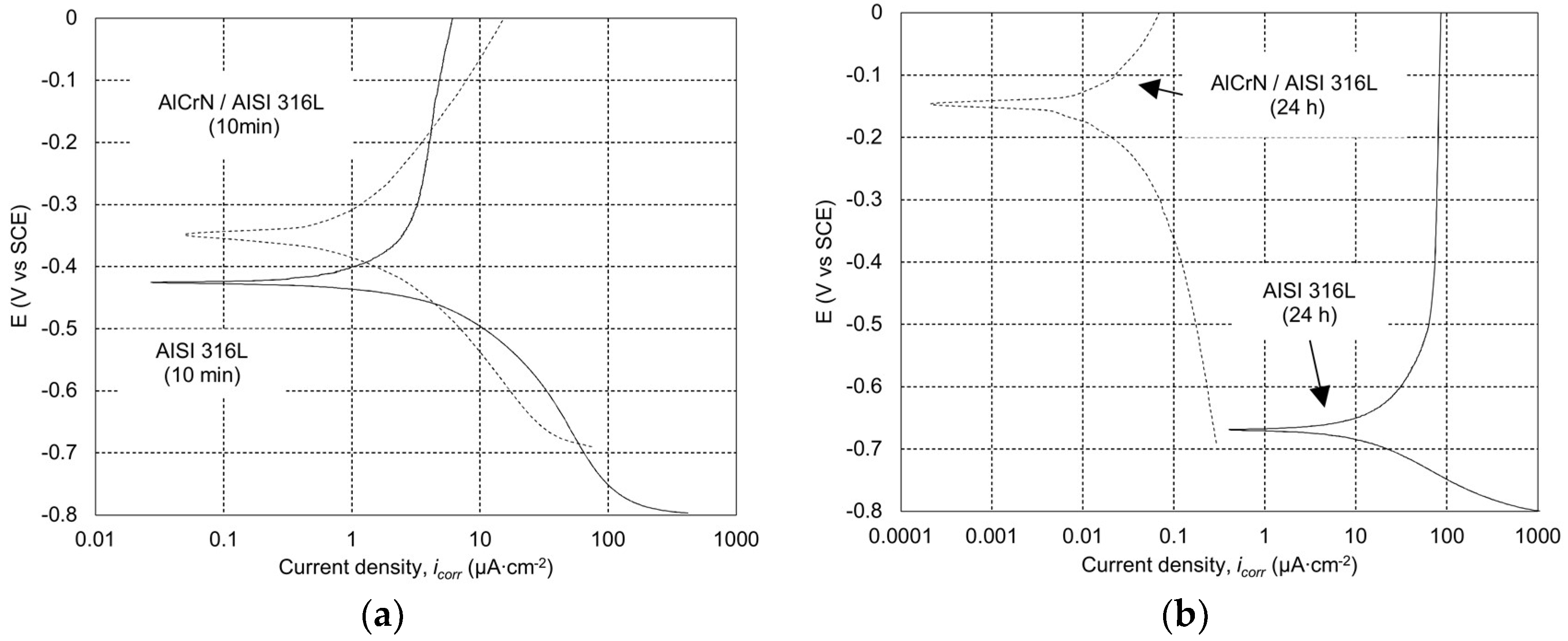
The Tafel plots and calculated potentiodynamic polarization results of the SS substrate and the coated specimens are presented in Figure 3 and Table 3, respectively. The Ecorr calc and icorr of the bare AISI 316L after 10 min of immersion were found to be −0.423 V vs. SCE and 1.9 µA∙cm−2, respectively. Ecorr calc shifts toward more positive value (to about −0.340 V vs. SCE) after applying the AlCrN PVD coating on the SS substrate. About 1.2 times lower icorr was measured as compared to the AISI 316L, reaching improvement in the protective efficiency (Pi) by 15.9%.
A significant passivation of the AlCrN PVD coated sample was found after immersion for 24 h. Ecorr calc significantly shifts toward a positive value (−0.153 V vs. SCE) and icorr was found to be ≈30 times lower (0.05 µA∙cm−2) as compared to the coating after 10 min immersion. The icorr was also found being ≈40 and ≈450 times lower as compared with the tested substrate after 10 min and 24 h immersion, respectively.
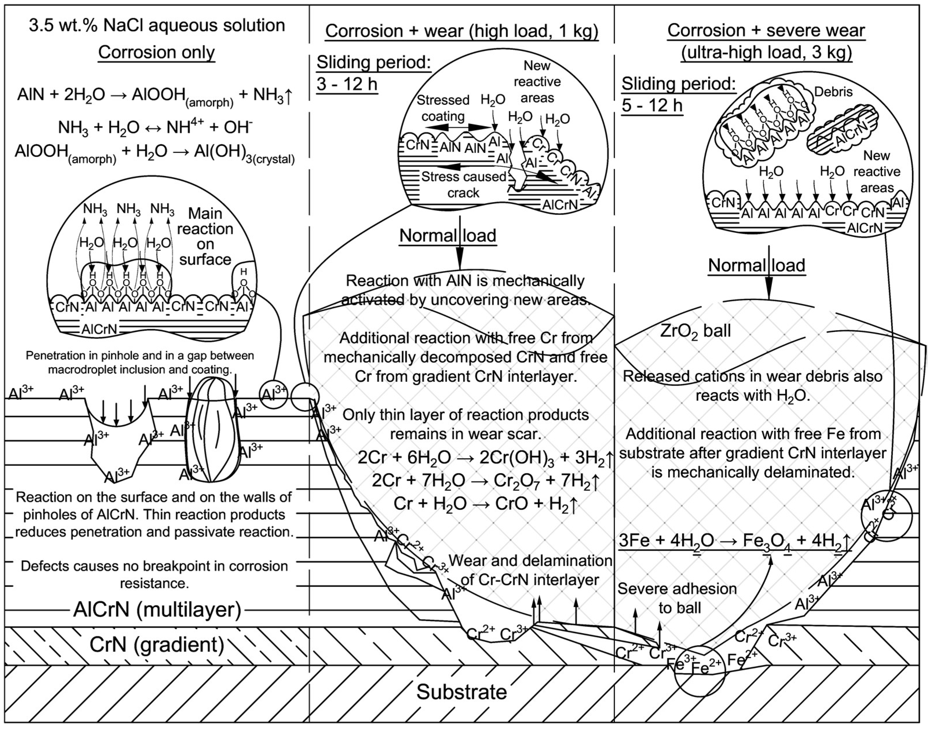
Decrease in CR down to 4.9 × 10⁻⁴ mm∙year−1 and F down to 0.002% for the AlCrN PVD coated sample was detected after 24 h immersion. It confirms a hydrolyzation reaction with the AlN on the surface and inside the pores. One of possible reaction is known as the Bowen’s model [23] reporting degradation of the AlN in an aqueous medium. In the present work, the reaction passivates as the AlN is embedded into a monolithic dense coating and the reaction occurs only on the surface. Corrosion products such as an amorphous aluminium monohydroxide (AlOOH(amorph)) and a crystalline aluminium hydroxide (Al(OH)3(crystal)) form an additional passivation layer. Increased Pi up to 99.8% confirms the inertness of transition metal (e.g., Cr) nitrides [24].
3.2. Tribo-Corrosive Wear Test of Uncoated and Coated SS AISI 316L
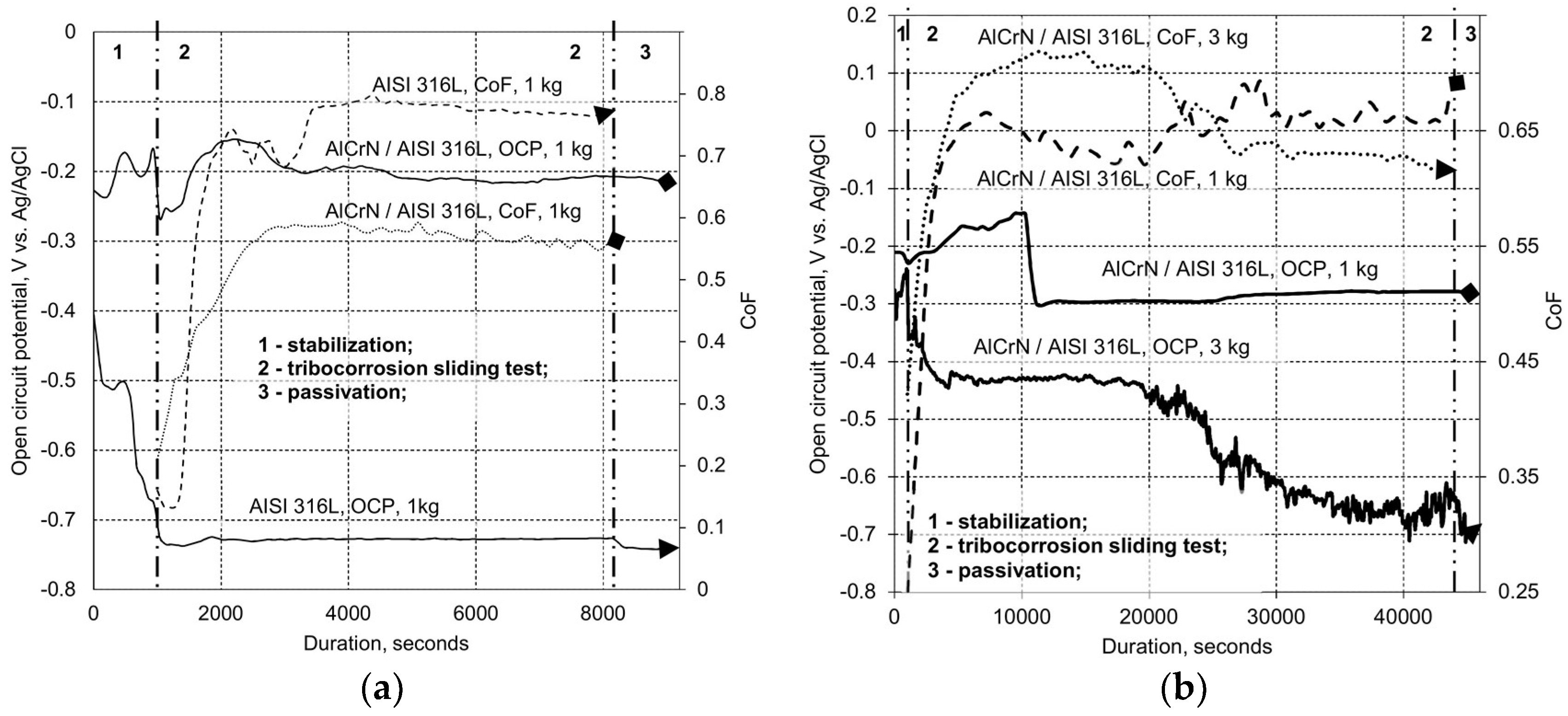
Evolution in OCP before, during and after the short (2 h) wear tests of the bare and coated SS are presented in Figure 4a. Loss of protective oxide film developed on the surface of the bare SS was continuously observed during the whole stabilization period (1000 s) before starting the wear test. OCP shifts towards negative values from about −0.400 down to about −0.680 V vs. Ag/AgCl during stabilization.
Sharp shifting towards more negative values of OCP was measured at the beginning of wear test. Stabilized OCP value of about −0.780 V vs. Ag/AgCl remains practically unchanged until the end of the test. A sharp increase in coefficient of friction (CoF) from about 0.10 up to about 0.74 in the first 1200 s of the wear test (running-in period) indicates a rapid formation of a wear track representing a removed protective oxide layer and an enlarging tribocontact area. Instability in CoF was observed as a fluctuation from 0.70 to 0.74, exhibiting arrangement of the tribosystem (second running-in period). A slightly higher, but stable CoF of about 0.79 was measured after 2600 s of the test running, which indicates reaching a steady-state regime.
Some fluctuations in OCP from −0.230 to −0.160 V vs. Ag/AgCl were observed with the AlCrN PVD coated steel before wear test. These fluctuations are related to the solution penetration into the pores, other defects presented on the surface of the coatings, and reaction with the available AlN, causing a formation of the passive layer that consists of Al-based reaction products. Simultaneous evolution during the first 1600 s and stabilization in OCP and CoF values of about −0.210 V vs. Ag/AgCl and 0.58 were observed corresponding to the running-in and the steady-state regime, respectively. At these particular conditions, neither failure nor observable degradation of the coating was detected.
The test duration was increased up to 12 h with the application of 1 or 3 kg load as shown in Figure 4b. The fluctuations in OCP from −0.320 up to −0.250 V vs. Ag/AgCl were generally observed with the AlCrN PVD coated steel before wear test initiation, Figure 4b. Evolution of CoF during a running-in period (about 4000 s from the beginning of wear test) is similar to the evolution of CoF at 1 and 3 kg loads. An increase in CoF was measured from 0.42 up to the steady-state value of 0.69. A second CoF stabilization period was observed after about 21,000 s of test running, changing CoF to the final steady-state value of 0.65 (1 kg) and 0.62 (3 kg).
A passivation effect of the coated specimen was detected during the test under 1 kg load. The OCP slightly changed from −0.240 up to a more positive value of −0.150 V vs. Ag/AgCl. A rapid change to more negative OCP value of −0.300 V vs. Ag/AgCl was detected after 9000 s of sliding. It can be explained by an increased rate of a continuous mechanical destruction of the passivating layer. A slight passivation effect occurs after about 25,000 s as OCP was measured to be changing from −0.300 up to the final steady-state value of −0.280 V vs. Ag/AgCl.
Sharp shifting in OCP toward more negative values from −0.240 down to −0.440 V vs. Ag/AgCl was observed after the first 3300 s of the test under 3 kg load as shown in Figure 4b. This value remained stable for about 18,000 s of sliding indicating an inability of corrosion products to create a stable passivation layer under this load. However, the critical failure of the coating was recognized after about 18,000 s of the test run. The OCP was measured to be almost continuously shifting towards negative values from −0.440 down to about −0.700 V vs. Ag/AgCl at the end of the test.
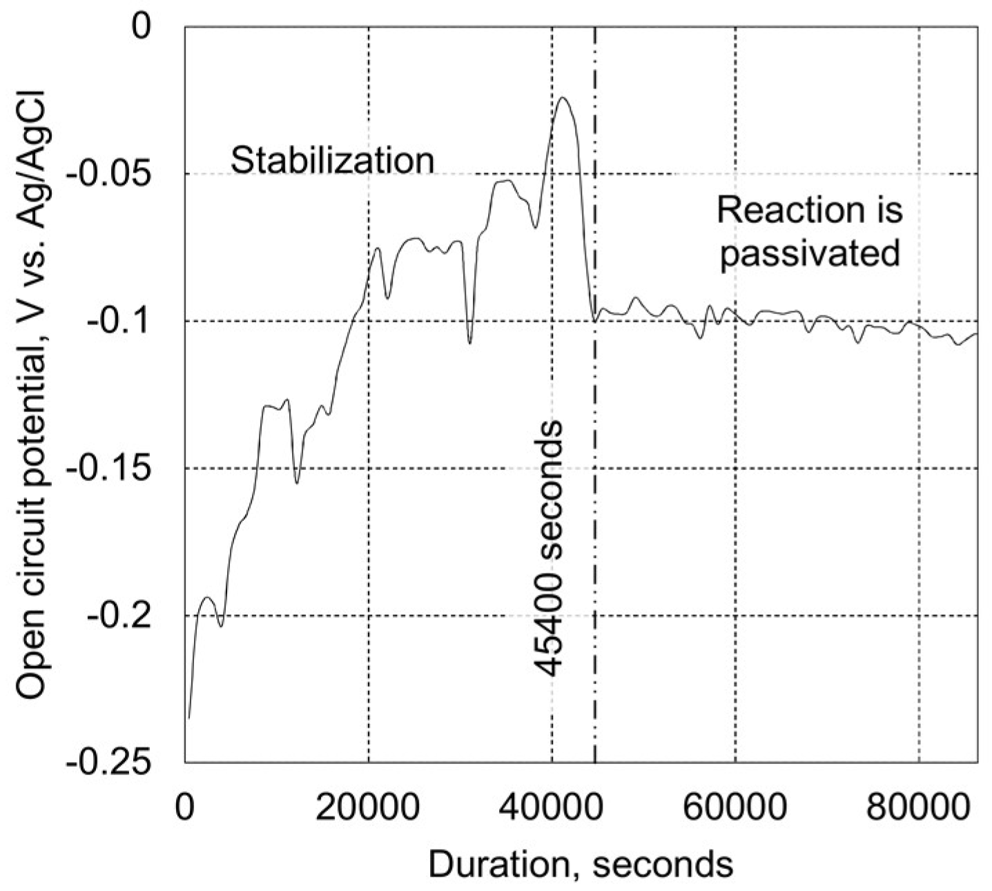
It was also found that passivation effect of the immersed AlCrN coating occurs after about 45,400 s of static oxidation as demonstrated in Figure 5. The stabilized OCP is more positive than during tribo-corrosion tests (Figure 4b).
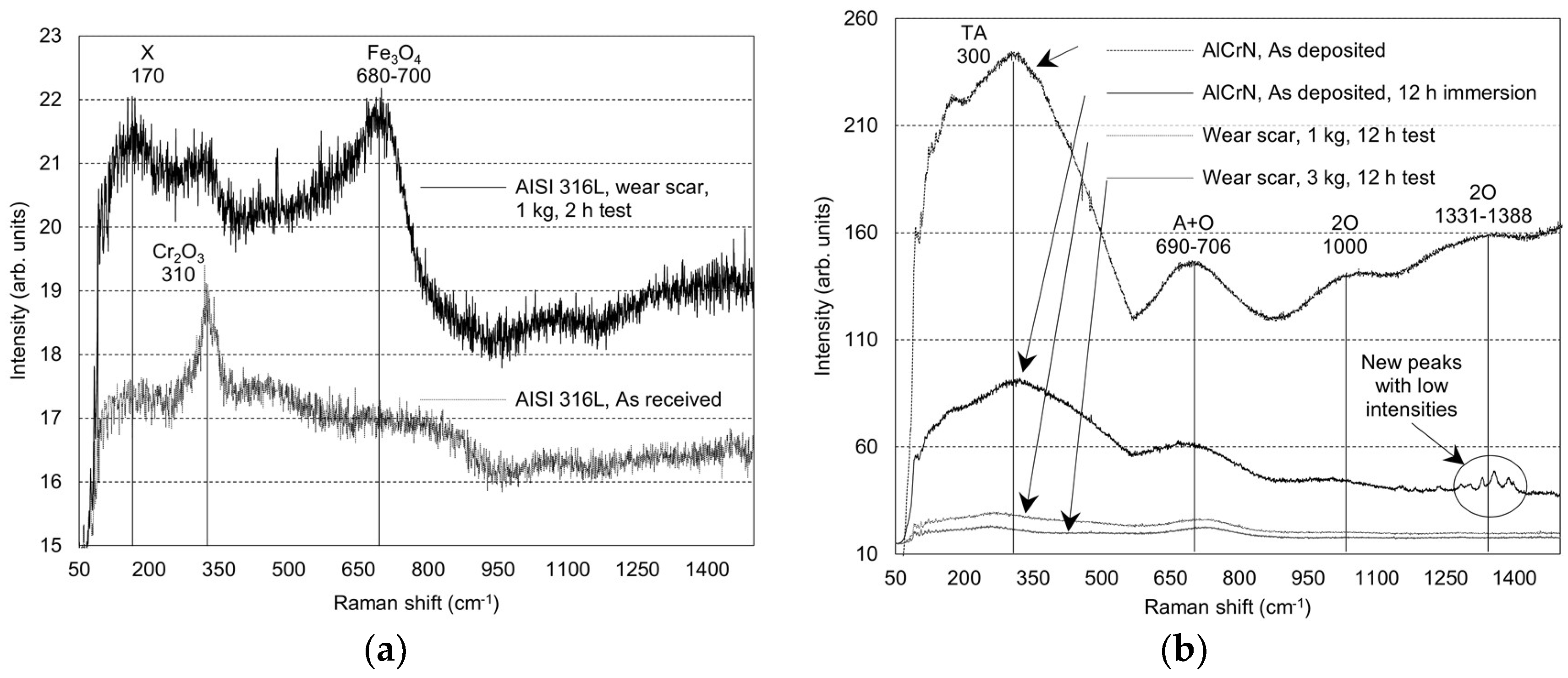
No typical iron based oxides on the pristine surface of the SS AISI 316L were found in the Raman spectra, Figure 6a. However, the Raman peak of Cr2O3 with a low intensity at 310 cm−1 indicates the development of the oxide layer at the ambient conditions. An increase in intensities of peaks collected from the area of a wear scar of the pristine SS points out to the formation of a thick layer of iron-based oxides and hydroxides [7]. A broad peak was observed in a range between 680 and 700 cm−1 indicates the presence of the corrosion product Fe3O4, Figure 6a. It should be noted that almost identical spectrum was obtained even after 24 h of static sample expose into the NaCl solution. Well-pronounced broad peaks appear in the spectra of the AlCrN PVD coated SS at 300, 690–706, 1000 and 1331–1388 cm−1, Figure 6b. These peaks belong to the vibration of Cr and N ions and their intensities decrease after immersion in the 3.5 wt % NaCl solution for 12 h. The peak at 1000 cm−1 disappears, but a broad peak at 1331–1388 cm−1 turns into new peaks of low intensities as demonstrated in Figure 6b. It could be explained by the low and medium intensity combination of Raman active modes and overtones of α-Cr2O3 on the surface of coated material [25].
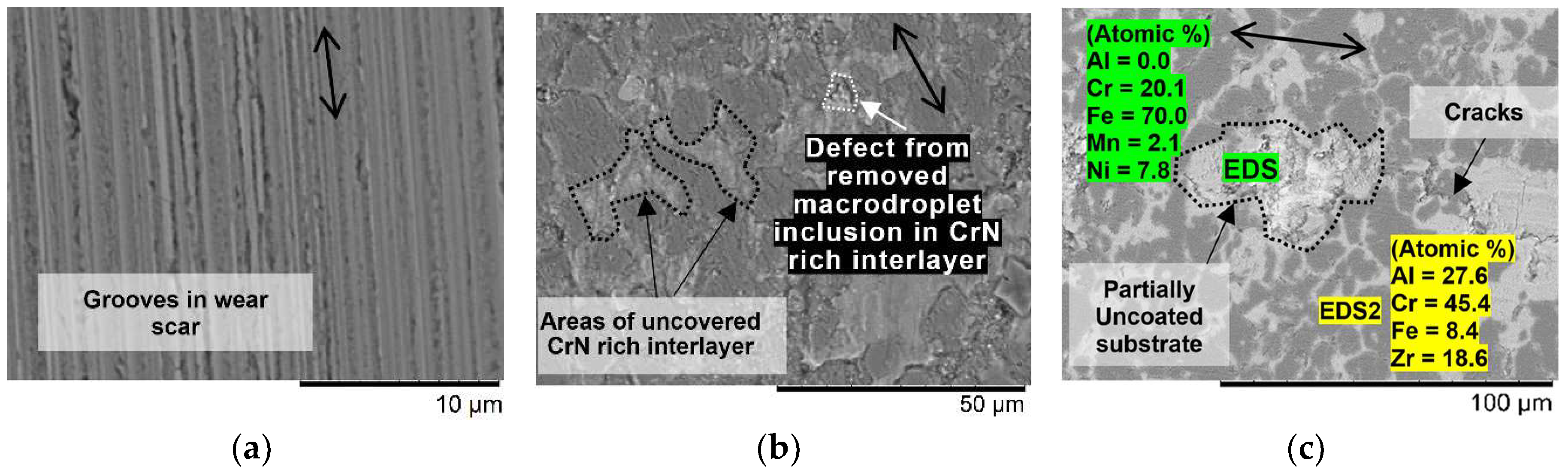
The typical grooves in the wear scar of the AISI 316L SS after the short tribo-corrosion test are demonstrated in Figure 7a. Several areas of the CrN rich interlayers and micro-droplet inclusions were exposed during an extended (12 h) tribo-corrosion test under 1 kg load, Figure 7b. Several areas of the uncovered CrN interlayer and extensive cracking in the middle region were found after the extended wear test under 3 kg load, Figure 7c. EDS analysis indicated a critical decrease in an atomic content of Al and appearance of elements typical for AISI 316L in the delaminated areas. The simplified schematic illustration of the static and dynamic corrosion processes is made based on the results obtained, Figure 8. The overview assignment of the Raman peaks of the uncoated and AlCrN coated SS AISI 316L before and after the corrosion and tribo-corrosion tests are presented in Table 4.
4. Discussion
The reaction and the subsequent passivation effect in the 3.5 wt % NaCl solution can be attributed to the formation of a very thin and mainly amorphous layer on the surface of the AlCrN coating [26]. This layer consists mainly of AlOOH(amorph), which foremost is a result of the reaction between H2O and AlN on the surface of the coating (including pinholes, gaps between microdroplet inclusions, etc.). The reactions are more intensive on the more defected areas of the surface. The applied incident powers of Nd-YAG induced laser (λ = 532 nm) of the Raman spectrometer checked from 0.05 up to 22 mW was not appropriate enough to detect this thin amorphous oxide layer due to massive side effects such as noise and/or weak signals. The CoF measurements in the conditions of the tribo-corrosive reciprocating sliding test demonstrate even lower final value at the ultra-high load (3 kg) as compared to the same test at a load of 1 kg. It indicates an intensive forming of a quite soft abrasive body of severely hydrolysed surfaces of the AlCrN-based wear debris (self-lubrication) at the extreme conditions as schematically shown in Figure 8. Self-lubrication effect provided by the hydrolyzation reaction with AlN can provide an improved reliability as a protective factor in a short period of overloading situations. It leads to significantly increased lifetime of coating in underwater conditions in addition to a high resistance to corrosion due to a presence of the interstitial compound of CrN.
It was found that the AlCrN coating is performing sufficiently better than TiCN or TiAlN coatings deposited onto the same SS substrate and tested by authors under the same tribo-corrosive conditions that indicate its higher reliability as the coating for protection of a soft steel substrate that can be produced by 3D printing (additive manufacturing technology) [2]. These TiCN and TiAlN coatings failed during 2-h sliding test with 1 kg load while the AlCrN coating was providing sufficient resistance up to the end of 12-h test with 1 kg load and failed only after 20,000 s of sliding with 3 kg load.
5. Conclusions
The multilayered AlCrN hard coating with the Cr adhesion and the gradient CrN interlayer was deposited on the SS substrate AISI 316L in a dominating cubic CrN structure by LARC PVD. The protective efficiency of the gradient AlCrN PVD coating increases up to 99.8% indicating a passivation layer developed through Al-based reaction products due to the reduced penetration rate of the corrosive media. The presence of surface defects (pinholes, inclusions, etc.) does not significantly affect the failure of coating in static corrosive conditions.
Tribo-corrosion tests performed in 3.5 wt % NaCl solution allows evaluation of the coating reactivity due to the AlN passivation effect combined with the presence of Al-based corrosion products. Change in OCP from −0.18 down to −0.3 V vs. Ag/AgCl after about 2 h-long sliding test under 1 kg load is related to the unprotected layer of Cr rich gradient CrN interlayer due to the partially lost layer of the AlCrN. An appearance and evolution of severe damages in the coating causes OCP shifting down to −0.42 V vs. Ag/AgCl at the beginning of sliding test under 3 kg load, indicating a mechanically initiated reaction with free Al from the AlN and free Cr from the AlCrN and CrN interlayer. The CoF of the coated samples remains about 25% lower (about 0.6) even after partial degradation as compared to the pristine SS under threefold lower load, indicating a reliability of the coating in tribo-contact even after a loss of chemical protection.
Author Contributions
Conceptualization, M.A. and I.H.; Methodology, J.B.; Software, T.R.; Validation, M.A., S.B. and I.H.; Formal Analysis, J.B.; Investigation, J.B.; Resources, M.A., S.B. and T.R.; Data Curation, J.B.; Writing-Original Draft Preparation, J.B.; Writing-Review & Editing, M.A. and I.H.; Visualization, J.B.; Supervision, M.A., I.H.; Project Administration, M.A.; Funding Acquisition, M.A. and I.H.
Funding
This research was supported by the Estonian Research Council under the personal grant (PUT1063) (I. Hussainova), Estonian Ministry of Higher Education and Research under Projects (IUT19-29 and IUT19-28), the European Union through the European Regional Development Fund, (Project TK141) and TTÜ base finance projects (B54, B56 and SS427) (M. Antonov).
Acknowledgments
The authors would like to thank Heinar Vagiström for the help with preparation of AlCrN PVD coatings. The authors would also like to thank Rainer Traksmaa and Arvo Mere for the help with XRD measurements.
Conflicts of Interest
The authors declare no conflict of interest. The founding sponsors had no role in the design of the study; in the collection, analyses, or interpretation of data; in the writing of the manuscript, and in the decision to publish the results.
References
- Wood, R.J.K. Tribo-corrosion of coatings: A review. J. Phys. D: Appl. Phys. 2007, 40, 5502–5521. [Google Scholar] [CrossRef]
- Holovenko, Y.; Antonov, M.; Kollo, L.; Hussainova, I. Friction studies of metal surfaces with various 3D printed patterns tested in dry sliding conditions. Proc. Inst. Mech. Eng. Part J J. Eng. Tribol. 2018, 232, 43–53. [Google Scholar] [CrossRef]
- Ricker, R.E.; Papavinasam, S.; Berke, N.; Brossia, S.; Dean, S.W. On using laboratory measurements to predict corrosion service lives for engineering applications. J. ASTM Int. 2008, 5, 1–10. [Google Scholar] [CrossRef]
- Fischer, A.; Mischler, S. Tribocorrosion: Fundamentals, materials and applications. J. Phys. D Appl. Phys. 2006, 39, 3120–3219. [Google Scholar] [CrossRef]
- Antonov, M.; Afshari, H.; Baronins, J.; Adoberg, E.; Raadik, T.; Hussainova, I. The effect of temperature and sliding speed on friction and wear of Si3N4, Al2O3, and ZrO2 balls tested against AlCrN PVD coating. Tribol. Int. 2018, 118, 500–514. [Google Scholar] [CrossRef]
- Stack, M.M.; Antonov, M.M.; Hussainova, I. Some views on the erosion–corrosion response of bulk chromium carbide based cermets. J. Phys. D Appl. Phys. 2006, 39, 3165–3174. [Google Scholar] [CrossRef]
- Larroumet, D.; Greenfield, D.; Akid, R.; Yarwood, J. Raman spectroscopic studies of the corrosion of model iron electrodes in sodium chloride solution. J. Raman Spectrosc. 2007, 38, 1577–1585. [Google Scholar] [CrossRef]
- Fenker, M.; Balzer, M.; Kappl, H. Corrosion protection with hard coatings on steel: Past approaches and current research efforts. Surf. Coat. Technol. 2014, 257, 182–205. [Google Scholar] [CrossRef]
- Dinu, M.; Mouele, E.; Parau, A.; Vladescu, A.; Petrik, L.; Braic, M. Enhancement of the corrosion resistance of 304 stainless steel by Cr–N and Cr(N,O) coatings. Coatings 2018, 8, 132. [Google Scholar] [CrossRef]
- Gutsev, D.; Antonov, M.; Hussainova, I.; Grigoriev, A.Y. Effect of SiO2 and PTFE additives on dry sliding of NiP electroless coating. Tribol. Int. 2013, 65, 295–302. [Google Scholar] [CrossRef]
- Zhang, L.; Chen, Y.; Feng, Y.; Chen, S.; Wan, Q.; Zhu, J. Electrochemical characterization of AlTiN, AlCrN and AlCrSiWN coatings. Int. J. Refract. Met. Hard Mater. 2015, 53, 68–73. [Google Scholar] [CrossRef]
- Baronins, J.; Podgursky, V.; Antonov, M.; Bereznev, S.; Hussainova, I. Electrochemical behaviour of TiCN and TiAlN gradient coatings prepared by lateral rotating cathode arc PVD technology. Key Eng. Mater. 2016, 721, 414–418. [Google Scholar] [CrossRef]
- Kaindl, R.; Franz, R.; Soldan, J.; Reiter, A.; Polcik, P.; Mitterer, C.; Sartory, B.; Tessadri, R.; O’Sullivan, M. Structural investigations of aluminum-chromium-nitride hard coatings by Raman micro-spectroscopy. Thin Solid Films 2006, 515, 2197–2202. [Google Scholar] [CrossRef]
- Johnson, D.F.; Jiang, D.E.; Carter, E.A. Structure, magnetism, and adhesion at Cr/Fe interfaces from density functional theory. Surf. Sci. 2007, 601, 699–705. [Google Scholar] [CrossRef]
- Lukaszkowicz, K.; Sondor, J.; Balin, K.; Kubacki, J. Characteristics of CrAlSiN + DLC coating deposited by lateral rotating cathode arc PVD and PACVD process. Appl. Surf. Sci. 2014, 312, 126–133. [Google Scholar] [CrossRef]
- Rana, D.; Mandal, B.M.; Bhattacharyya, S.N. Analogue calorimetric studies of blends of poly(vinyl ester)s and polyacrylates. Macromolecules 1996, 29, 1579–1583. [Google Scholar] [CrossRef]
- Benedek, I.; Feldstein, M.M. Fundamentals of pressure sensitivity. In Handbook of Pressure-Sensitive Adhesives and Products; CRC Press: Boca Raton, FL, USA, 2008. [Google Scholar]
- Kawate, M.; Kimura Hashimoto, A.; Suzuki, T. Oxidation resistance of Cr1−xAlxN and Ti1−xAlxN films. Surf. Coat. Technol. 2003, 165, 163–167. [Google Scholar] [CrossRef]
- Samani, M.K.; Chen, G.C.K.; Ding, X.Z.; Zeng, X.T. Thermal conductivity of CrAlN and TiAlN coatings deposited by lateral rotating cathode arc. Key Eng. Mater. 2010, 447–448, 705–709. [Google Scholar] [CrossRef]
- Nohava, J.; Dessarzin, P.; Karvankova, P.; Morstein, M. Characterization of tribological behavior and wear mechanisms of novel oxynitride PVD coatings designed for applications at high temperatures. Tribol. Int. 2015, 81, 231–239. [Google Scholar] [CrossRef]
- Somiya, S.; Aldinger, F.; Spriggs, R.M.; Uchino, K.; Koumoto, K.; Kaneno, M. Handbook of Advanced Ceramics: Materials, Applications, Processing, and Properties. In Handbook of Advanced Ceramics; Elsevier: New York, NY, USA, 2003. [Google Scholar]
- ASTM G59-97e1 Standard Test Method for Conducting Potentiodynamic Polarization Resistance Measurements; ASTM International: West Conshohocken, PA, USA, 1997.
- Bowen, P.; Highfield, J.G.; Mocellin, A.; Ring, T.A. Degradation of aluminum nitride powder in an aqueous environmet. J. Am. Ceram. Soc. 1990, 73, 724–728. [Google Scholar] [CrossRef]
- Yang, M.; Allen, A.J.; Nguyen, M.T.; Ralston, W.T.; MacLeod, M.J.; DiSalvo, F.J. Corrosion behavior of mesoporous transition metal nitrides. J. Solid State Chem. 2013, 205, 49–56. [Google Scholar] [CrossRef]
- Gomes, A.S.O.; Yaghini, N.; Martinelli, A.; Ahlberg, E. A micro-Raman spectroscopic study of Cr(OH)3 and Cr2O3 nanoparticles obtained by the hydrothermal method. J. Raman Spectrosc. 2017, 48, 1256–1263. [Google Scholar] [CrossRef]
- Barshilia, H.C.; Selvakumar, N.; Deepthi, B.; Rajam, K.S. A comparative study of reactive direct current magnetron sputtered CrAlN and CrN coatings. Surf. Coat. Technol. 2006, 201, 2193–2201. [Google Scholar] [CrossRef]
Figure 1.
A schematic illustration of the multilayered AlCrN PVD coating on the stainless steel substrate (a); and XRD (made by Rigaku Ultima IV, Tokyo, Japan) diffractogram of AlCrN PVD coating deposited onto stainless steel AISI 316L substrate, indicating a dominating cubic CrN phase in the coating (b).

Figure 2.
Surface defects on the as-deposited AlCrN coating on the stainless steel AISI 316L substrate were detected in a SEM micrograph (a); and a schematic illustration of reciprocating tribo-corrosion test setup (b).
Figure 2.
Surface defects on the as-deposited AlCrN coating on the stainless steel AISI 316L substrate were detected in a SEM micrograph (a); and a schematic illustration of reciprocating tribo-corrosion test setup (b).

Figure 3.
Potentiodynamic polarization curves (Tafel plots) of uncoated and AlCrN PVD coated AISI 316L specimens indicating corrosion potential: (a) after 10 min immersion; (b) after 24 h immersion.
Figure 3.
Potentiodynamic polarization curves (Tafel plots) of uncoated and AlCrN PVD coated AISI 316L specimens indicating corrosion potential: (a) after 10 min immersion; (b) after 24 h immersion.

Figure 4.
Chronopotentiometry results to show comparison in evolution of CoF and open circuit potential (vs. Ag/AgCl) of uncoated and the AlCrN PVD coated AISI 316L samples during short (2 h) (a); and extended (12 h) tribo-corrosion test of coated AISI 316L sample (b).
Figure 4.
Chronopotentiometry results to show comparison in evolution of CoF and open circuit potential (vs. Ag/AgCl) of uncoated and the AlCrN PVD coated AISI 316L samples during short (2 h) (a); and extended (12 h) tribo-corrosion test of coated AISI 316L sample (b).

Figure 5.
Chronopotentiometry result to show evolution of open circuit potential (vs. Ag/AgCl) of AlCrN PVD coated AISI 316L sample in the 3.5 wt % NaCl solution (static test duration–86,400 s/24 h).
Figure 5.
Chronopotentiometry result to show evolution of open circuit potential (vs. Ag/AgCl) of AlCrN PVD coated AISI 316L sample in the 3.5 wt % NaCl solution (static test duration–86,400 s/24 h).

Figure 6.
Raman spectra illustrates vibration modes and oxides on pristine surface of AISI 316L and in a wear scar after 2 h (1 kg) tribo-corrosion wear test (a); and observed changes of intensities and shifting of peaks on coated specimens before and after 12 h immersion; and after extended (12 h) tribo-corrosion wear tests in 3.5 wt. NaCl % under 1 and 3 kg loads (b).

Figure 7.
SEM micrographs show grooves inside wear scars after short (2 h) tribo-corrosion test with AISI 316L (a), and defects after extended (12 h) tribo-corrosion tests with AlCrN coated AISI 316L specimens under 1 kg (b), and 3 kg loads (c). Double arrowed line shows reciprocating sliding direction; elemental analysis was done with EDS inside and close to the marked area.

Figure 8.
Simplified schematic illustration indicates main processes on the surface and in the wear scar during static corrosion and 12 h tribo-corrosion tests. A period when damage of interlayer or substrate took place in case of 1 or 3 kg tests, respectively is indicated. A ball is shown only for illustration without scaling. Mainly released cations are indicated.


Table 1.
Properties of coating and ball materials.
| Properties | AlCrN | YSZ |
|---|---|---|
| Hardness at 20 °C, GPa | 30.6 ± 2.8 [5] * | 10.5 ** |
| Fracture toughness KIC, MPa∙m0.5 | 6.4 [18] | 6.0 ** |
| Young's modulus of elasticity, GPa | 585 ± 54 [5] * | 210 ** |
| Thermal conductivity 20 °C, W m−1∙K−1 | 1.5 [19] | 3 ** |
| Max service temperature, °C | 900 [20] | 1200 ** |
| Density, kg∙m−3 | – | 6000 ** |
| Thermal diffusivity, ×10−6∙m2∙s−1 | – | 0.9 [21] |
| Diameter, mm | – | 10 |
Notes: * Property from coating from the same production line; ** Properties are provided by producer.
Table 2.
Applicability of different methods for laboratory evaluation of various aspects of reliability of coatings intended for corrosive tribo-applications.
Table 2.
Applicability of different methods for laboratory evaluation of various aspects of reliability of coatings intended for corrosive tribo-applications.
| Task | Method | ||||||||||||
|---|---|---|---|---|---|---|---|---|---|---|---|---|---|
| Visual and Tactile Observation | Optical Microscopy | SEM | 2D Contact Profilometry | 3D Topography | KaloMax Ball Cratering | Adhesion Testing | Scratch Testing | Electrochemical Corrosion Tests | Tribo-Corrosive Test* | EDS | Raman Spectroscopy | XRD | |
| Preliminary evaluation | + | + | + | ++ | +++ | +++ | +++ | +++ | + | NCH | ++ | ++ | +++ |
| Wear or corrosion rate | - | + | + | +++ | +++ | NCH | NCH | NCH | ++ | +++ | - | - | - |
| Destruction mechanisms | + | + | ++ | ++ | +++ | NCH | NCH | + | + | ++ | + | +++ | ++ |
| Elemental or phase composition of thin tribo-layer | - | - | - SE | NCH | NCH | NCH | NCH | - | 0 | 0 | - | +++ | - |
| Elemental or phase composition of thick (≈>1 um) tribo-layer | - | 0 | + BSE | NCH | NCH | NCH | NCH | - | 0 | 0 | ++ | +++ | ++ |
| In-Situ measurement of corrosion intensity and/or evolution of coating damage | 0 | 0 | NCH | NCH | NCH | NCH | NCH | NCH | +++ | +++ | - | - | + |
Notes: “+” is showing how useful could be the equipment (+ min, ++ average, +++ max); “-” means that equipment is rather not useful; “0”–only qualitative estimation or indirect conclusion; NCH–not considered here; SE and BSE–Secondary electron and Backscattered electrons of SEM; * Assisted with potentiostat/galvanostat.
Table 3.
Potentiodynamic polarization of uncoated and coated specimens.
| Material | Potentiodynamic Polarization Measurements (From NOVA) | Calculation Results | ||||||
|---|---|---|---|---|---|---|---|---|
| Corrosion Current Density | Polarization Resistance | Calculated Corrosion Potential | Tafel Slope | Tafel Slope | Corrosion Rate | Protective Efficiency | Porosity | |
| icorr | Rpm, Rp | Ecorr calc | |βa| | |βc| | CR | Pi | F | |
| [µA∙cm−2] | [Ω∙cm−2] | [V] | [V∙Decade−1] | [V∙Decade−1] | [mm∙Year−1] | [%] | [%] | |
| AISI 316L, 10 min | 1.9 | 1.43 × 10⁴ | −0.423 | 0.718 | 0.069 | 2.0 × 10⁻² | – | – |
| AlCrN/AISI 316L, 10 min | 1.6 | 3.76 × 10⁴ | −0.340 | 0.399 | 0.212 | 1.7 × 10⁻² | 15.9 | 29 |
| AISI 316L, 24 h | 22.1 | 1.71 × 10³ | −0.669 | 0.312 | 0.121 | 2.3 × 10⁻¹ | – | – |
| AlCrN/AISI 316L, 24 h | 0.05 | 2.33 × 10⁶ | −0.153 | 0.488 | 0.517 | 4.9 × 10⁻⁴ | 99.8 | 0.002 |
Table 4.
Assignment of Raman peaks before and after corrosion and tribo-corrosion tests.
| Material | Test | Peak Position [cm−1] | Peak Assignment | Peak Intensity | Peak Configuration | Comments |
|---|---|---|---|---|---|---|
| AISI 316L | As received | 310 | Cr2O3 | Low | Sharp | Slight oxidation after polishing |
| 24 h static immersion | 680–700 | Fe3O4/γ-Fe2O3 | Low | Broad | Development of Fe based oxides and hydroxides | |
| Tribo-corrosion 2 h, 1 kg | 680–700 | Fe3O4/γ-Fe2O3 | Low | Broad | Development of Fe based oxides and hydroxides | |
| AlCrN PVD on AISI 316L | As deposited | 300 | TA mode-vibration of Cr ions | High | Broad | Cubic CrN structure |
| 690–706 | A+O optic mode-vibration of N ions | High | Broad | Cubic CrN structure | ||
| 1000 | 2 O-second order transition | Low | Broad | Cubic CrN structure | ||
| 1331–1388 | 2 O-second order transition | Low | Broad | Cubic CrN structure | ||
| 12 h static immersion | 300 | TA mode-vibration of Cr ions | High | Broad | * | |
| 690–706 | A+O optic mode-vibration of N ions | High | Broad | * | ||
| 1000 | 2 O-second order transition | Low | Broad | * | ||
| 1331–1388 | - | Low | Sharp | Possible formation of Al based corrosion products | ||
| Tribo-corrosion 12 h, 1 kg | 300 | TA mode-vibration of Cr ions | Low | Broad | * | |
| 690–706 | A+O optic mode-vibration of N ions | Low | Broad | * | ||
| Tribo-corrosion 12 h, 3 kg | 300 | TA mode-vibration of Cr ions | Low | Broad | Formation of corrosion products | |
| 690–706 | A+O optic mode-vibration of N ions | Low | Broad | Formation of corrosion products. |
Note: * Intensity decreases due to the formation of amorphous AlOOH [22].
© 2018 by the authors. Licensee MDPI, Basel, Switzerland. This article is an open access article distributed under the terms and conditions of the Creative Commons Attribution (CC BY) license (http://creativecommons.org/licenses/by/4.0/).
Share and Cite
MDPI and ACS Style
Baronins, J.; Antonov, M.; Bereznev, S.; Raadik, T.; Hussainova, I. Raman Spectroscopy for Reliability Assessment of Multilayered AlCrN Coating in Tribo-Corrosive Conditions. Coatings 2018, 8, 229. https://doi.org/10.3390/coatings8070229
AMA Style
Baronins J, Antonov M, Bereznev S, Raadik T, Hussainova I. Raman Spectroscopy for Reliability Assessment of Multilayered AlCrN Coating in Tribo-Corrosive Conditions. Coatings. 2018; 8(7):229. https://doi.org/10.3390/coatings8070229
Chicago/Turabian StyleBaronins, Janis, Maksim Antonov, Sergei Bereznev, Taavi Raadik, and Irina Hussainova. 2018. "Raman Spectroscopy for Reliability Assessment of Multilayered AlCrN Coating in Tribo-Corrosive Conditions" Coatings 8, no. 7: 229. https://doi.org/10.3390/coatings8070229
Note that from the first issue of 2016, this journal uses article numbers instead of page numbers. See further details here.