Effect of Laser Scanning Speed on the Wear Behavior of Nano-SiC-Modified Fe/WC Composite Coatings by Laser Remelting

School of Mechanical and Electrical Engineering, Jiangxi University of Science and Technology, Ganzhou 341000, China
*
Author to whom correspondence should be addressed.
Coatings 2018, 8(7), 241; https://doi.org/10.3390/coatings8070241
Submission received: 6 June 2018
/
Revised: 24 June 2018
/
Accepted: 28 June 2018
/
Published: 7 July 2018
(This article belongs to the Special Issue Nanocomposite Coatings)
Abstract
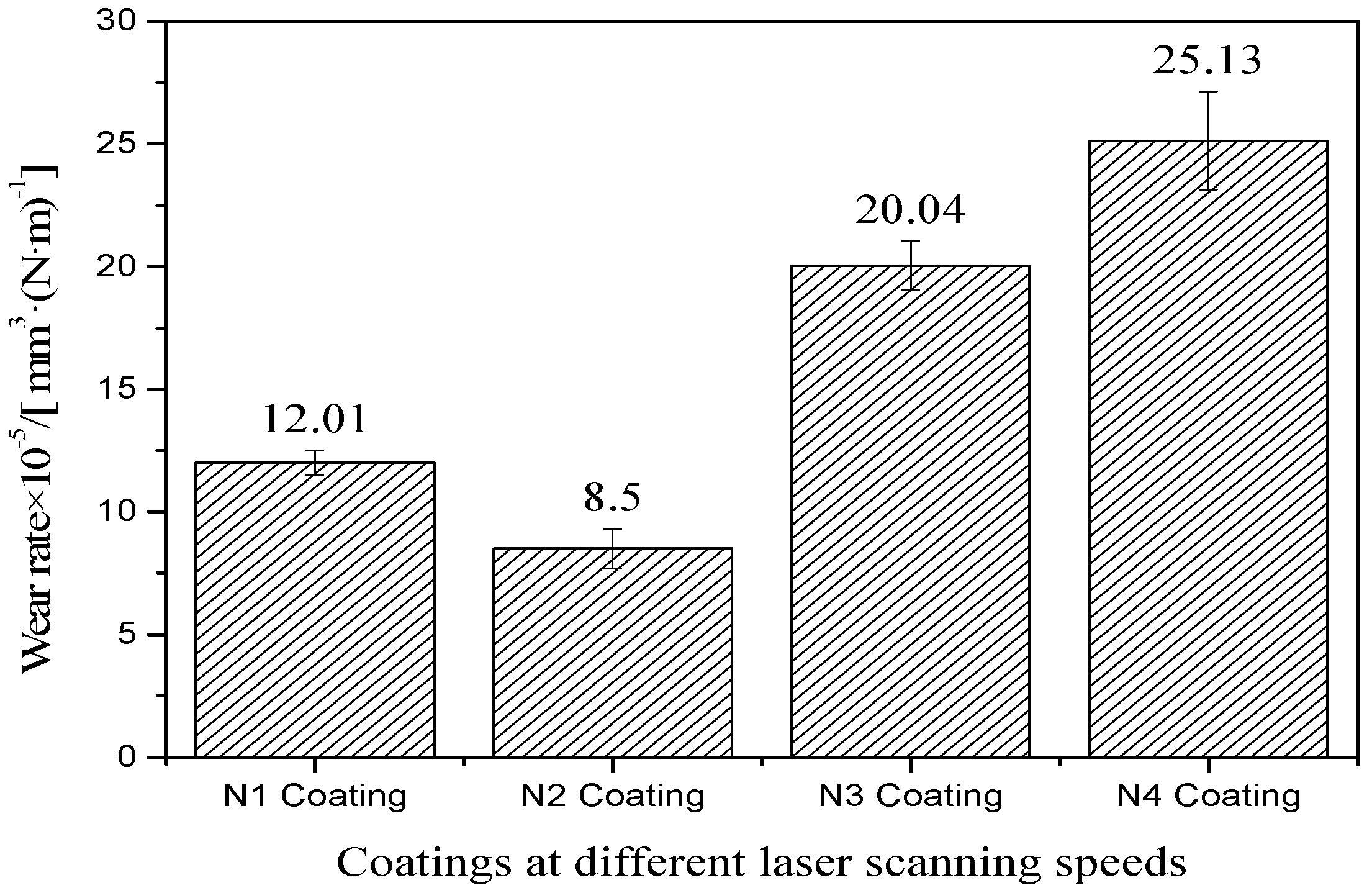
:A supersonic plasma sprayed nano-SiC-modified WC/Fe metal–cermet composite coating was remelted with a fibre-pulsed laser at four different laser scanning speeds (100, 150, 200 and 250 mm·min−1) while the other parameters were kept constant. The microstructures, microhardness, and tribological properties of the coatings were analysed by means of SEM (scanning electron microscopy), XRD (X-ray diffractometer), and a friction tester, respectively. The results show that, when the laser scanning speed is 100 mm·min−1, the remelted coating is most dense with regard to the coverage of the substrate. The coating with nano-particles became more smooth, and elements Si and C in the nano-particles reacted with Fe, Ni, or Cr and formed a hard mesophase that enhanced the strength and hardness of the coating. With the increase of laser scanning speed, the hardness of the four coatings increased first and then decreased, and the nano-SiC-modified remelted coating showed a maximum microhardness of about HV0.51350, and the nano-particles made the coating’s micro-structure finer, at a laser scanning speed of 150 mm·min−1. The friction coefficient and wear rate of the four coatings were 0.58 and 12.01 × 10⁻⁵ mm3/(N·m), 0.21 and 8.50 × 10⁻⁵ mm3/(N·m), 0.62 and 20.04 × 10⁻⁵ mm3/(N·m), and 1.23 and 25.13 × 10⁻⁵ mm3/(N·m). The remelted coating at a laser scanning speed of 150 mm·min−1 exhibits the best wear resistance and its wear mechanism is governed by slight adhesion wear and plastic deformation.
1. Introduction
In order to meet the requirements of a variety of different conditions, many engineering components must have more superior properties, such as excellent abrasion resistance and corrosion resistance [1,2]. 45steel is a high-quality carbon structural steel that is easy to cut and is used for processing shafts, steel pipes, and other common parts [3]. Although 45steel has excellent machinability and a low processing cost, its hardness and wear resistance should be further improved [4,5]. At present, plasma spraying is one of the most suitable techniques for preparing wear-resistant metal–ceramic coatings because of its high temperature (about 18,000 °C) during the spraying process and that the risk of deformation of the substrate material is small (the substrate’s surface temperature does not exceed 300 °C) [6,7,8]. Nano-particles have more excellent performance than common materials because of their unique structure and properties (such as quantum size, small size, and surface effect) and have been widely used in metallurgy, machinery, aviation, aerospace, and other fields. However, the sprayed coating usually has high porosity, tissue unevenness, and other defects [9,10]. In recent decades, laser surface remelting has been used to eliminate these defects [11,12,13,14,15].
There are many process parameters that can affect the quality of a laser-remelted coating. Laser remelting has a great influence on the microstructure and properties of the coating due to the content of nano-particles and the uniformity of the dispersion distribution. These process parameters determine the structure and properties of the remelted coating. Optimising the above process parameters can eliminate or reduce various organisational and performance defects produced in the laser remelting process to obtain a high-quality, laser-remelted surface modification coating. Ge [16] investigated the effect of different laser powers (1500 to 4500 W) on the microstructure and wear resistance of a cladding coating with the laser cladding technique on the surface of AZ31B magnesium alloy. The results show that the size of the dendritic structure increases with the increase of the laser power. When the laser power is 3000 W, the microhardness of the coating is the highest and the wear resistance is the best. Gao et al. [17] prepared an Al–Cu laser-clad alloy coating on the surface of AZ91HP magnesium alloy by the laser cladding technique. It was found that the dilution rate of the coating material increases with the increase of the laser power, the microhardness of the coating is the highest, and the wear resistance and corrosion resistance are the best, when the laser power is 2500 W. Then, the hardness and wear resistance began to decline with the increase of laser power. Cheng et al. [18] explored the influence of laser power on the microstructure and hardness of a WC/Ni wear-resistant coating preset on the surface of a 42CrMo alloy by fibre laser. The results indicated that the coating structure is coarsened with increasing laser power and the WC particles decompose Fe/C compounds, thus reducing the hardness of the coating. García et al. [19] studied the effect of laser scanning trajectories and remelted area on the wear resistance of laser-remelted NiCrBSi coatings. They found that the laser scanning trajectory has little effect on the coating wear rate and the coating exhibits the best abrasion resistance when the area of the remelting is 46%. Each of the process parameters of laser remelting is critical to the quality and performance of the coating, and the laser scanning speed directly determines the amount of laser energy absorbed by the coating per unit area over a given period of time, thereby affecting the microstructure of the coating. However, the effect of the laser scanning speed on the tribological properties of a laser-remelted coating has, to date, been rarely reported on. Therefore, how the laser scanning speed affects the tribological properties of a laser remelted coating is worthy of discussion.
In this paper, 45steel was used as the substrate material. A nano-SiC-modified WC/Fe coating was preliminarily deposited on the substrate by way of a plasma spraying technique before being remelted by laser. The laser scanning speed was investigated for its effects on the tribological properties of the laser remelted coating and to provide theoretical support for the preparation of better laser-remelting-modified coatings in industrial applications.
2. Experimental Procedure
2.1. Test Materials and Coatings Preparation
The substrate material was a 45 steel, and it was machined into a ring shape: Ø50 × Ø40 × 10 mm. The substrate was pretreated by degreasing, grinding, and sand blasting before plasma spraying.
The plasma spray powders used were ZX.Fe40 and ZX.Ni60+35WC; their chemical composition is shown in Table 1 and Table 2, respectively. The ZX.Fe40 and ZX.Ni60+35WC were mixed in a ratio of 9:1 (wt. %). Both powders had a particle size of 53 μm. The plasma spray coating was prepared by an atmospheric plasma spraying system and cooled by air. Its thickness was about 0.4 mm. The process parameters are shown in Table 3.
The laser remelting test was carried out using fibre-pulsed lasers (model AXL-600AW, Aoxin laser Co., Ltd., Dongguan, China), and the scanning track is a ring-shaped path. The remelting process parameters were: laser power 600 W, spot diameter 1.5 mm, lap amount 10%, and an argon protective gas atmosphere. The scanning speeds were 100, 150, 200 and 250 mm·min−1 (designated coatings N1, N2, N3 and N4, respectively). A nano-SiC ceramic powder, with a particle size of 40 nm, was used as a filler in an amount of 0.5 wt. % during the laser remelting. The nano-SiC powder was put into a paste with a binder polyvinyl alcohol and uniformly coated on the surface of the plasma coating. Its thickness was 0.2 to 0.3 mm. Then, it was dried in a vacuum oven at a temperature of 100 to 120 °C for 1.5 h.
2.2. Friction and Wear Test
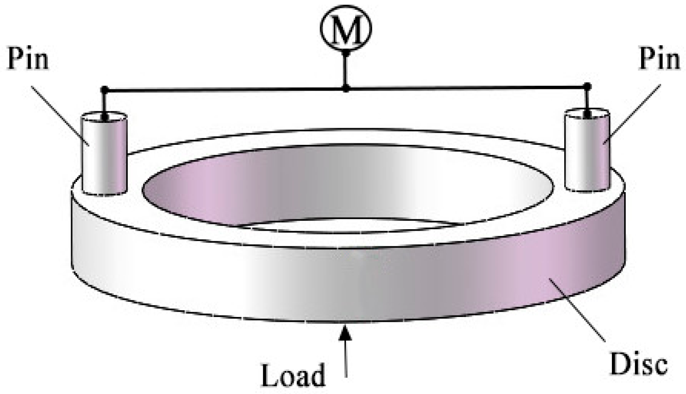
The wear experiments were carried out using microcomputer-controlled high-temperature and high-speed friction and wear testing machine (model MMG-10, Zhongyi Instruments Co., Ltd., Shandong, China). The wear method was large pin-disc friction. The process for generating friction is shown in Figure 1.
The nano-SiC-modified remelted surfaces of all the samples were sanded with sandpaper, polished to a flat surface to be worn, then rinsed with acetone and dried before the test. All the samples were washed with acetone and dried again after the test.
The grinding material used was a GH21 high-temperature alloy steel with a size of Ø4 × 12 mm and a hardness of 50 to 55 HRC. The test parameters are listed in Table 4. The friction coefficient was automatically recorded in real-time by the friction and wear testing machine during the test. According to the Archard theory, the wear rate was calculated using the following formula [20,21]:
where W is the wear rate; V is the wear volume (mm3); F is the normal load (N); and L is the total wear sliding distance (m). The wear volume is given by V = AL, where A is the cross-sectional area of the abrasive and L is the diameter of the abrasive. The test was repeated three times under each condition, and the final wear rate was the average of three test data.
2.3. Testing and Characterization
The microstructure and wear morphology of nano-SiC-modified remelted coatings were observed by MLA650F field emission scanning electron microscopy (SEM, MLA650F, FEI, Hillsboro, OR, USA), and the microanalysis was undertaken using an X-ray energy dispersive spectrometer (EDS).
The phase of the laser remelted coatings was detected by a SMART APEX П X-ray diffractometer. An HRS-150 microhardness tester (Fangce Instruments Co., Ltd., Shenzhen, China) was used to test the hardness of the coatings under a load of 0.9 N and a loading time of 15 s. Each point was tested three times; thereafter, the average value was taken as the final hardness value.
3. Results and Discussions
3.1. Macroscopic Morphology of Remelted Coatings
Figure 2 shows the macroscopic morphology of four laser-remelted WC/Fe composite coatings. It can be seen that, for the four kinds of nano-SiC-modified remelted coatings, they had a significant metallic lustre and the surface was basically smooth; however, there were differences between the coatings as a consequence of the different laser scanning speeds. The remelting trajectory of the N1 coating disappeared and was not obvious. Besides this, it had a high overlap rate, which was due to the fact that the coating drew a large amount of laser energy at a lower laser scanning speed. A small number of circular bumps appeared on the surface of the N3 coating, which was caused by localized remelting caused by an increase in laser scanning speed. There were a lot of nodules and bubbles on the surface of the N4 coating because the laser scanning speed was too high and the energy absorbed by the surface material per unit of time decreased, resulting in the laser providing energy that was only absorbed by most of the surface material such that the substrate material was almost unmelted and thus formed continuous tear-like aggregates [22]. The surface of the N2 coating was flat and defect-free.
3.2. Microstructural Analysis of Remelted Coatings
3.2.1. Microstructure of Section
Figure 3 shows a cross-sectional micrograph of a plasma-sprayed coating. It can be seen that the coating has a lamellar stacking structure in which the white flakes are unmelted WC particles and they are distributed evenly in the coating. There is a lot of pores in the coating, and the bond band of the coating and the substrate is uneven, which was the result of incompletely melted particles during the spraying. In general, the density of the coating was not high and the coating was mechanically bonded with the substrate. There is an obvious transition zone between the coating and the substrate.
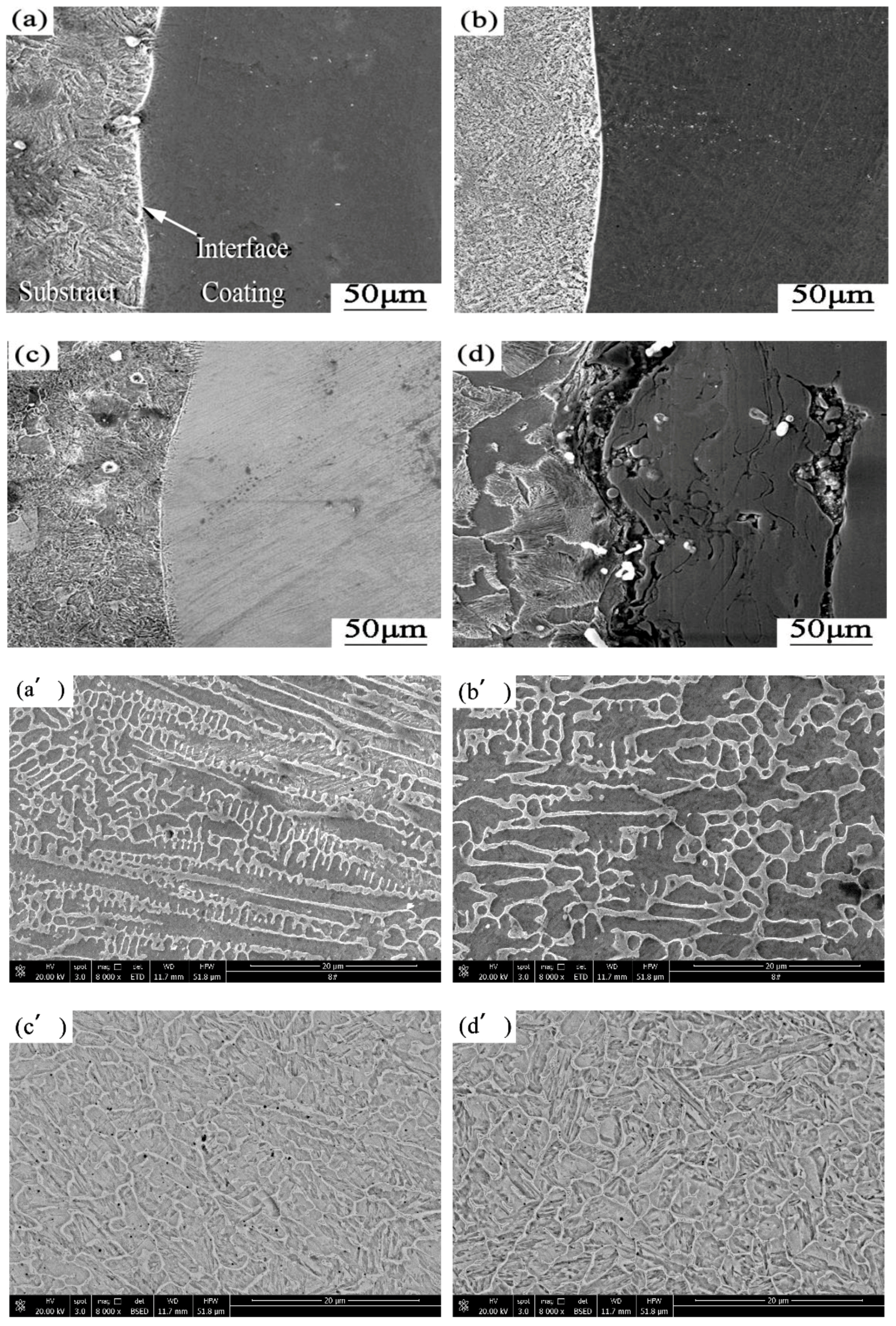
Figure 4 shows the cross-sectional morphology of the four remelted coatings. It can be seen clearly that most of the pores, cracks, and lamellar structures of the plasma-sprayed coating subjected to laser remelting have disappeared and most of the unmelted WC particles are remelted [23]. In general, the laser remelting treatment improved the density of the plasma spray coating greatly, and the shrinkage stress can be reduced with the nano-ceramic particles of the coating during cooling and solidification. The morphology of the liquid/solid interface and the microstructural evolution were influenced by the G/R ratio, where G is the actual temperature gradient between the solid/liquid metal cross-sections and R is the cure rate [24]. The G/R ratio is influenced by the scanning speed and the faster the scanning speed, the larger the G/R radio is. Si was decomposed from nano-SiC particles and reacted with Fe and Cr to form hard mesophases. These hard mesophases increased the latent heat of fusion in the molten pool. The temperature, fluidity, and surface tension were improved in the molten pool and contributed to the discharge of gases and the homogenization of the components. The ratio of G/R at the cross-section of the substrate and the melt zone is very high, and this high ratio results in planar solidification at the interface and a white solidification zone between the coating and the substrate [25,26]. WC and W2C were the main phases of the white solidification zone. The more obvious the white solidification zone is, the better the bonding state of the coating and the substrate is, and the higher the degree of melting. It can be seen that the white coagulation bands of coatings N1 and N2 are more obvious and the white coagulation of N2 coating is smooth and curved so as to form a good metallurgical bond. The white solidification zone of the N3 coating is faint compared with those of coatings N1 and N2, and there a clear line between the coating and the substrate. This indicated that a metallurgical bond with less bond strength has been formed between the coating and the substrate. The N4 coating is simply mechanically bonded to the substrate, and the bonding interface retains the state of plasma spraying since the laser does not penetrate the coating, only some of the surface material is melted, and the nano-particles were not fully remelted. This corresponds to the analysis of the macroscopic morphology of this coating in Figure 2.
The metallographic microstructure of the cladding regions in the N1, N2, N3 and N4 coatings is shown in Figure 4a’–d’ below, respectively. An analysis shows that, in the range of 100–150 mm·min−1, the scanning speed was low, the rate of laser energy absorption was higher, the cooling rate of the coating was slower, the cladding area could absorb a lot of heat, the melting duration was longer—in which the crystal bubble had enough time to grow up so that the lattice volume was large and the number was small—and the microstructure was relatively coarse. Nano-particles were pinned and dislocated at the microstructure. There occurred lattice distortion in the cladding area of the N1 coating and the N2 coating, and its structure was similar to a "fish bone" structure. In the range of 200–250 mm·min−1, the scanning speed was high and the cladding area was subjected to rapid melting and solidification. The gradient of the temperature changed greatly, resulting in a large number of crystal nuclei and more lattice. The distance between the internal lattices decreased after the grain refinement of the remelted coating. So, the microstructure of the N3 coating and the N4 coating is more intensive.
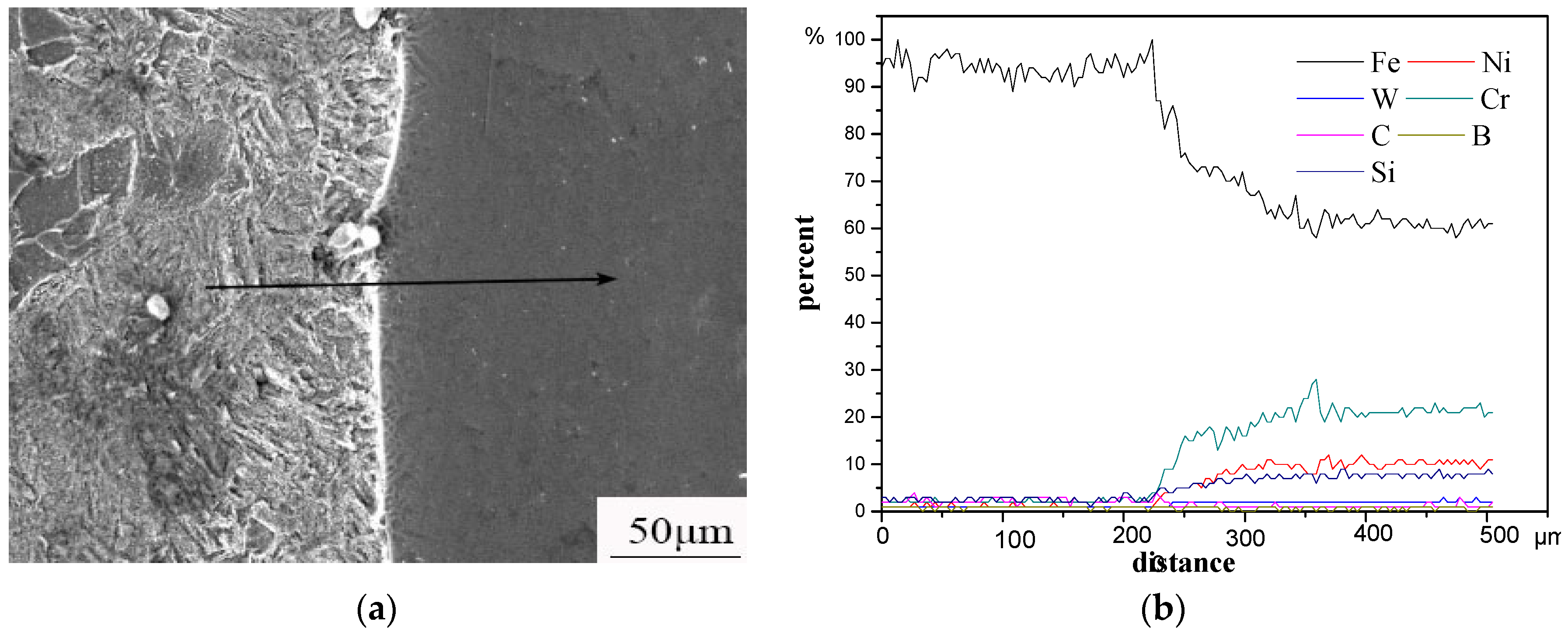
Figure 5 shows the cross-section elemental distribution of the coatings at a scanning speed of 50 mm·min−1. The content of Fe decreased sharply at 230 μm, and that of W, Cr and Si was increased in different degrees. This was due to the elements in the molten pool mutually diffusing each other driven by the concentration difference. SiC decomposed partly at a high temperature, and Si and C can react with Fe, Ni, Cr, and other elements in the coatings to form a hard mesophase and enhance the strength and hardness of the coatings.
The slower the scanning speed was, the more the SiC was undecomposed. The undecomposed nano-SiC particles can act as the core of heterogeneous nucleation due to their small size, break the continuity of the dendritic structure of the coatings, and play a role in grain refinement.
3.2.2. Microhardness of the Coatings
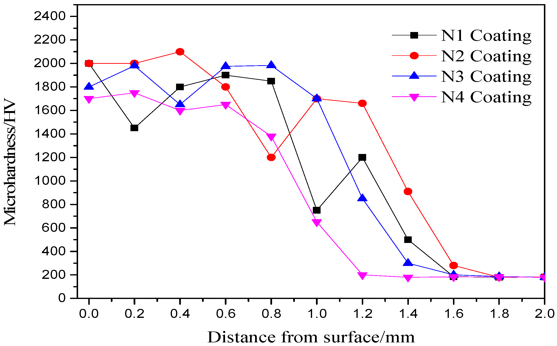
Figure 6 shows the hardness distribution of the nano-SiC-modified remelted coatings at different laser scanning speeds. The microhardness of the remelted coatings increases first and then decreases along with an increase in the laser scanning speed. The depth of the hardened layer decreases with the increase of the laser scanning speed. The nano-particles can refine grains, reduce cracks and pores, and obtain better performance from nano-composite ceramic coatings. When the scanning speed was low, which was a speed in the range of 100–150 mm·min−1, the time of laser heating was longer and the method of strengthening was solid solution strengthening. The main elements in the coating were Fe and Cr. They have similar atomic sizes and can generate a replacement solid solution at high temperature so that the lattice can produce a stress field where the distortion energy is stored. The nano-particles were pinned and dislocated at the microstructure. When there was a dislocation, the stress field interacts with it, so that the dislocations are bound and the coating is reinforced. When the scanning speed was low, which was a speed in the range of 100–150 mm·min−1, the coating was heated very quickly by laser heating and then the rapid cooling made a large undercooling, which made the nuclei grow fast. The alloying elements in the molten pool formed a variety of compounds and, finally, a lot of fine microstructures were formed. The coating was remelted faster than others when the scanning speed was 100 mm·min−1, and the microhardness of the coating was lower than that produced at other scanning speeds. This is because the nano-SiC formed large particles under the highest remelted temperature. The method of strengthening was fine grain strengthening, and, theoretically, the hardness would increase with an increase in scanning speed [27]. Additionally, the coatings’ hardness was increased compared to other scanning speeds due to the fact that the amount of plastic deformation can be improved significantly [28,29]. However, the heating time was short, the energy absorbed by the coating was insufficient, the interaction between the laser beam and the surface of the plasma spray layer was weak, and the depth of the hardened layer of the remelted coating was insufficient even when there was the structure of the plasma spray coating. So, the hardness will be reduced.
The hardness curve is divided into three distinct steps corresponding to the coating of the cladding area, the heat-affected zone, and the substrate. The heat-affected zone is close to the cladding area where the effect of a high-energy density laser is more significant and its temperature will reach the austenite critical temperature, so its hardness will be improved. The grain of the remelted layer was refined when nano-SiC particles were added. The substrate material is far from the laser where the heat dissipation is rapid and the energy absorption rate is very low, so its microstructure cannot be changed and its hardness was unchanged. In the hardened layer, the average hardness of the N3 coating is higher than that of the N2 coating. However, too much increase in microhardness will lead to a lower rate of improvement in wear resistance [30]. At the same time, it can be seen from the figure below that the thickness of the coating is about 0.4 mm higher than that of the plasma spray. This is because the substrate and the coating were melted together when the high-energy laser was used.
3.3. Tribological Properties
3.3.1. Coefficient of Friction and Wear Rate
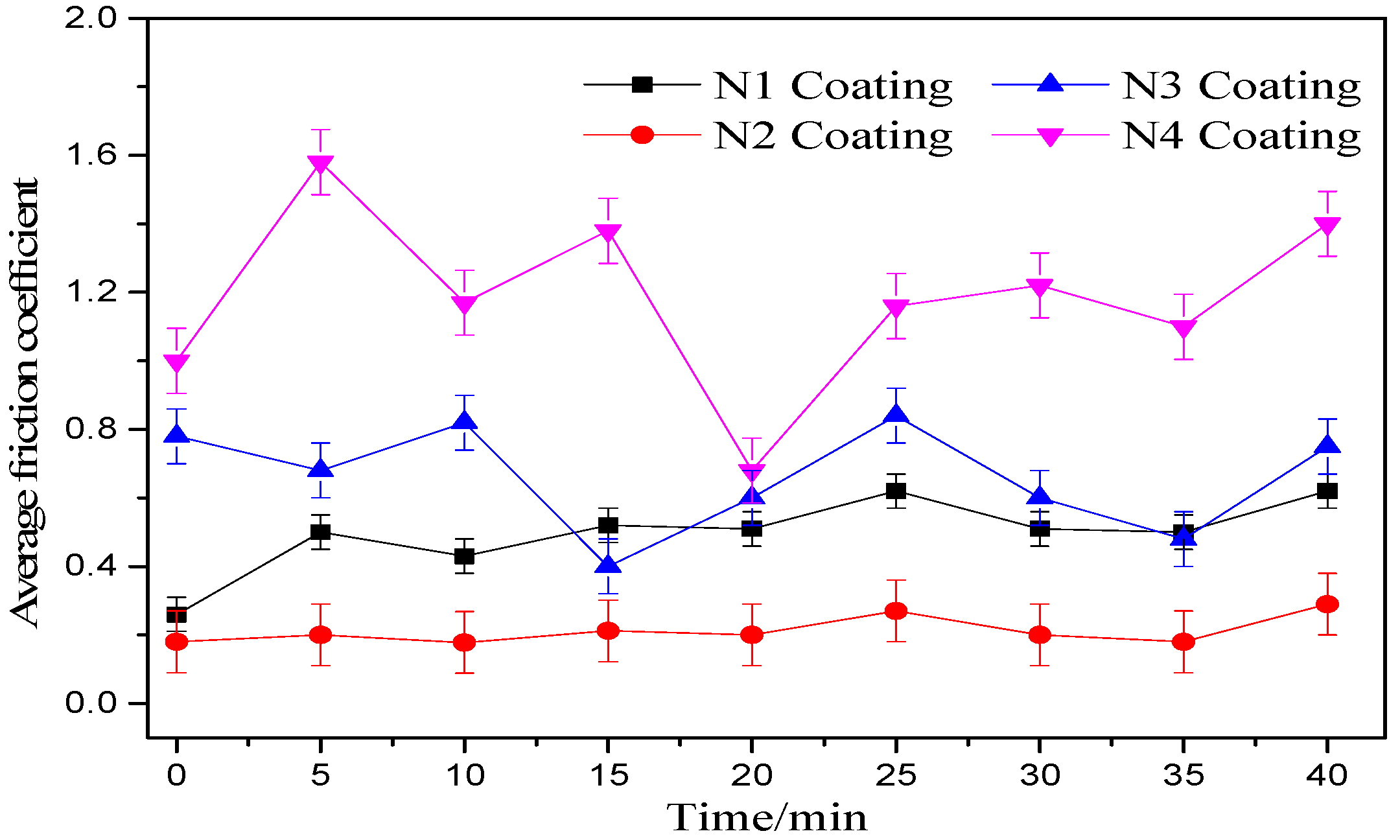
Figure 7 shows the friction coefficient versus time plots for the nano-SiC-modified remelted coatings. The friction coefficient of the N1 coating and the N2 coating were less than those of the N3 coating and the N4 coating. This is because the laser scanning speed used on the N3 coating and the N4 coating was higher than that used on the N1 coating and the N2 coating, and at a large scanning speed the coating is not completely melted and the method is not conducive to solid solution strengthening. In addition, the N4 coating had the largest coefficient of friction, and the volatility was very large: the N3 coating is second only to the N4 coating in that regard because the coating speed was too fast, the coating absorbed too little energy, and the nodules and tear-like aggregates on the coated surface increased the frictional resistance as shown by the macroscopic appearance of the remelted coatings in Figure 2. Since the laser scanning speed of the N1 coating and the N2 coating was low, sufficient energy was absorbed, recrystallisation occurred in the plasma spray coating, and a large amount of hard ceramic phase was precipitated, so the coefficient of friction was low [31].
Figure 8 shows the change in wear rate of the nano-SiC-modified remelted coatings. As can be seen from Figure 6, the wear rate of the laser remelted coating decreases first and then increases. The wear rate reached the minimum, and maximum, at a laser scanning speed of 150 and 250 mm·min−1, respectively. This is because, as the scanning speed increases, the dendritic size and interplanar spacing in the remelted coating decreases, the organisation of the grains is significantly refined, and the dilution rate of the substrate to the coating is also lowered, resulting in a slight increase in microhardness [32]. That is because the size of the nanoparticles was very small and it can interrupt the growth of the dendrite during cooling of the coatings. The coatings’ plastic deformation can be improved with the refinement of the dendrite structure. The grains were refined by nano-SiC particles so that the pores in the remelted layer were filled and the interface strength at the grain boundaries and the density of the remelted layer were improved. The large particles shed can be effectively suppressed during the wear process. The resistance of crack propagation was increased with nano-SiC particles. However, with the high energy absorbed by a coating at a low scanning speed, the nanoscale particles can form an aggregation easily, which may have caused higher wear rates. A scanning speed of 250 mm·min−1 will lead to an incompletely melted coating without rapid melting and recrystallisation, thus hindering any improvement in the hardness and wear resistance.
3.3.2. Wear Morphology and Composition Analysis
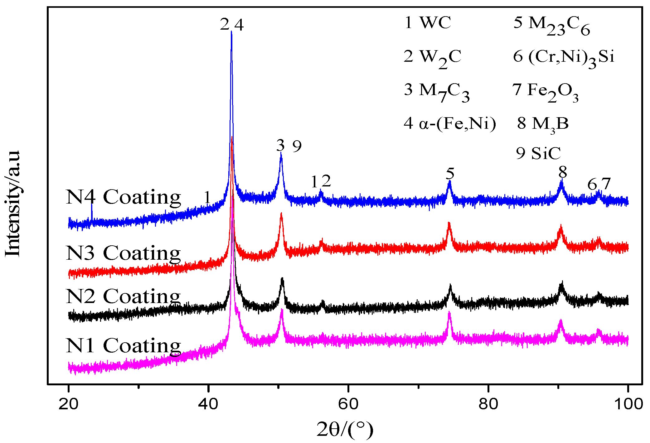
Figure 9 shows the XRD patterns of the wear surface of the nano-SiC-modified remelted coatings. SiC particles could reduce coating cracks and pores because the diameter of a nano-SiC particle is very small and pores and cracks in the coating can be filled by nano-particles. Besides this, SiC particles were pinned in the coating, which improved the coatings’ plastic deformation capacity and increased the crack propagation resistance. The main phases of the wear surface were WC, W2C, M7C3, SiC, α-(Fe, Ni), M23C6, (Cr, Ni)3Si, and so on. In the process of plasma spraying and laser remelting, WC particles decomposed in the high-temperature environment as follows: WC → W + C, 2W + C → W2C. The decomposed C atoms will combine with other elements to produce a cubic structure of an M6C-type carbide. The elements Si and C in the nano-particles can react with Fe, Ni, Cr, and other elements in the coating to form a hard mesophase and enhance the strength and hardness of the coating. For example, in the melted WC and Fe, Ni is generated (Fe, Ni)6C, and its dispersion is high. W2C has a dense hexagonal structure, and it was dispersed in the coating and played a role in the strengthening. M7C3 is a large hardened carbide structure (about 0.5 μm in diameter) with a complex structure, and it is a hardening phase with a high melting point and hardness. M23C6 is a smaller carbide (about 0.1 to 0.2 μm) with a face-centred cubic structure [33]. It also can be seen that when the laser scanning speed is changed from 100 to 250 mm·min−1, the grain size of the remelted coatings decreases first and then increases, reaching a minimum at a scanning speed of 150 mm·min−1.
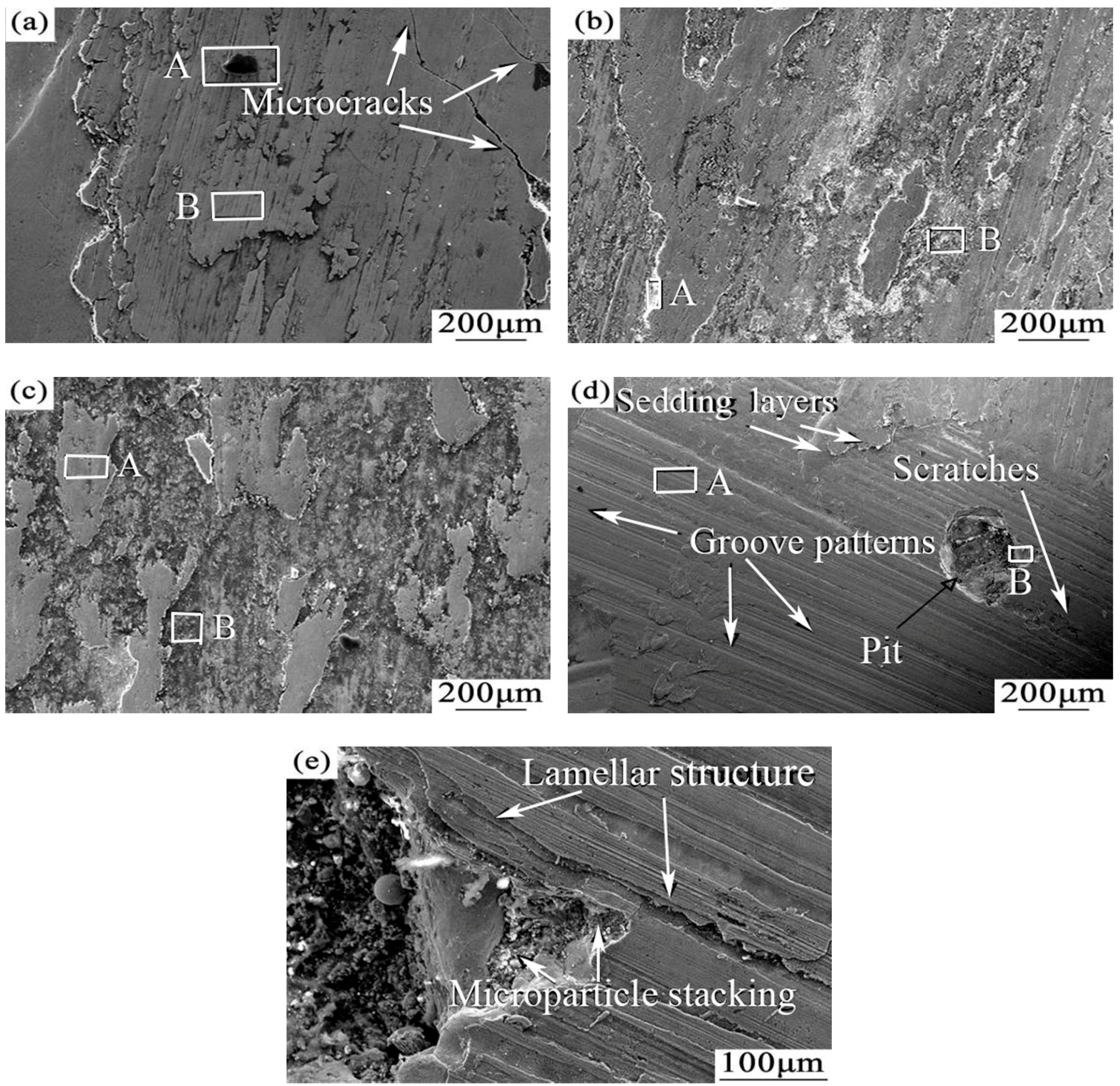
Figure 10 shows the wear surface morphology of the nano-SiC-modified remelted coatings. It can be seen from Figure 10a that the wear surface of the N1 coating has a decreasing mass and many microcracks. Nano-particles can also refine grains, reduce cracks and pores, and obtain better performance from coatings [34]. The wear mechanism is a mixture of adhesive wear and fatigue wear. The formation of microcracks is the result of embrittlement of ceramic materials at high temperatures. The coating could have absorbed a lot of energy as the laser scanned very slowly, but the ceramic phases which have been formed, such as M7C3, M23C6, and (Cr, Ni)3Si, have large differences in thermal expansion coefficients with the substrate material, which resulted in excessive temperature gradients inside the coatings. It can be seen from Figure 10b that the wear surface of the N2 coating is very rough and accompanied by the transfer of material caused by the loss of the block, indicating that a fracture in the surface material occurred via the wear mechanism of adhesive wear. As can be seen from Figure 10c, a large amount of the surface material has been peeled off from the N3 coating (to a greater extent than with the N2 coating). The sub-surface of the N3 coating is exposed. It can be seen from Figure 10d that the wear surface of the N4 coating is covered with grooves, shedding layers (small amounts), and abrasions, which are typical of abrasive wear. In addition, a pit also appeared on the worn surface of the N4 coating, which may be because, at too fast a laser scanning speed, only some local regions on the plasma spray coating are melted while the other regions are not melted, which leads to a loss of material under the alternating load in the friction process. Figure 10e is an enlarged view of the pit in Figure 10d. The wear-resistant sub-surface still has a lamellar structure and a microparticle stacking structure of the plasma spraying coating, which is caused by the N4 coating being formed at too fast a laser scanning speed, thus preventing it from melting and recrystallising for subsequent plasma spray coatings.
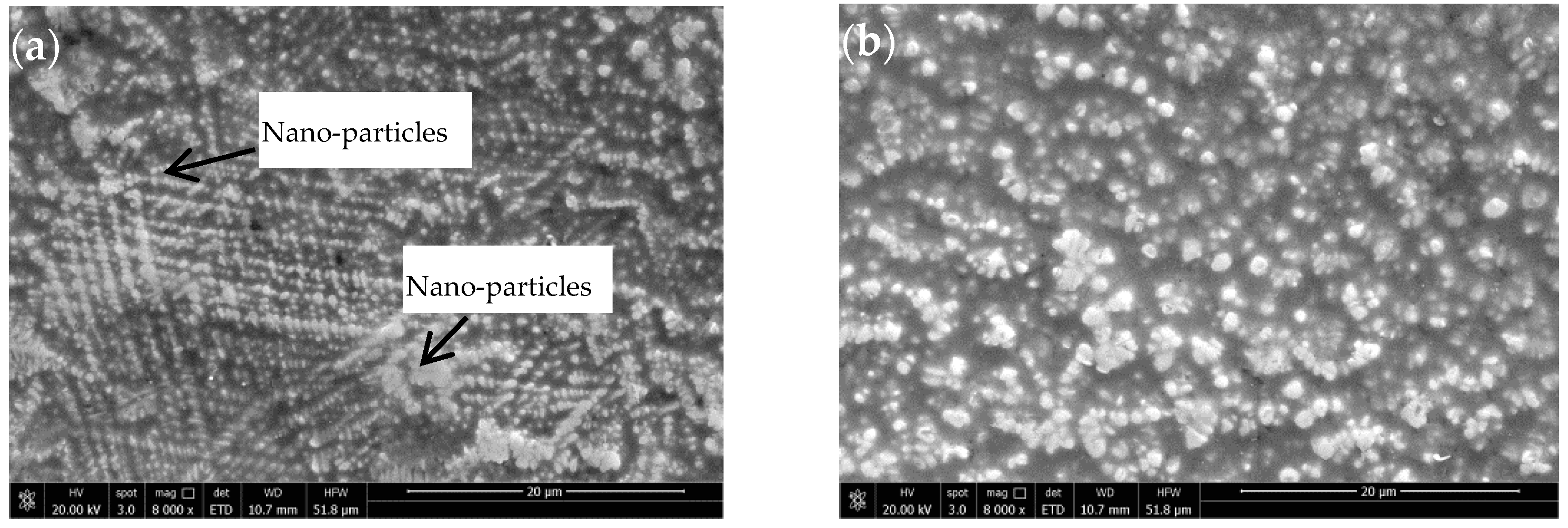
The number of grain boundaries and the grain size can be increased by adding nano-particles, and this can also improve the plastic deformation ability and mechanical properties of coatings. Nanoparticles were pinned, dislocated, and evenly distributed on the surface of the coatings. The tendency for crystal cracking and the plastic deformation capability of the coatings were improved. Figure 11a,b show the micro-morphology of the remelted surface at a scanning speed of 200 and 100 mm·min−1, respectively. Nanoparticles are prone to agglomerate due to their small size. SiC particles distributed less in Figure 11b compared to Figure 11a because the SiC decomposed more under a low scanning speed.
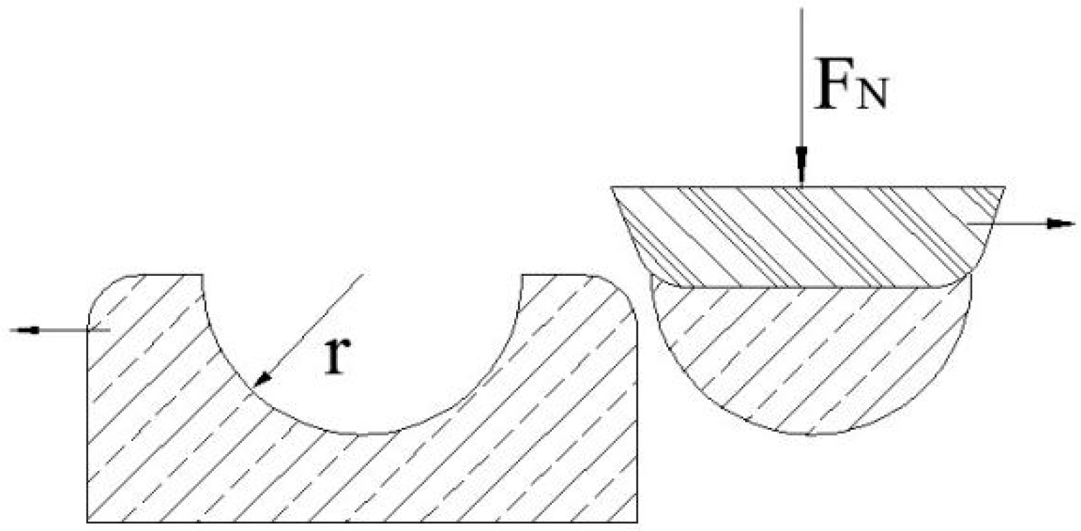
The generation of tiny pits is the result of plastic deformation of the surface material of the coating from the perspective of elastoplastic mechanics, which belongs to the adhesion wear. According to Archard’s adhesive wear theory, the following models (Figure 12) can be used to analyze the causes of tiny pits [35].
Assuming that the cross-section of the frictional contact area between the micro-protrusions and the coating on the grinding pin is a circle with radius r and the grinding debris is hemispherical, the cross-sectional area of each contact area is πr2. In this paper, for the friction contact area in the plastic contact state, the support load is
When the displacement of the grinding movement is 2r, then the volume of wear can be expressed as:
Additionally, because not all of the grinding debris are hemispherical, we can introduce a wear coefficient K and usually have . Then, the formula can be written as:
On both sides of the same time divided by the real contact area are:
Additionally, because the depth of wear is and the pressure is , the above formula can be sorted as:
For the entire wear surface, there is
where L is the sliding displacement; P is the surface pressure; and H is the material hardness.
As can be seen from the Equation (7), the coating surface’s wear depth is determined by the sliding displacement, surface pressure, and hardness. In the friction test, the wear sliding displacement L of the four coatings is the same, and the pressure P of the N4 coating is the largest. From the hardness curve of each coating (Figure 4), the hardness of the N4 coating is the lowest hardness, so it is the most likely to produce pits. Therefore, the factors that determine whether or not pits are produced are the hardness of the coating and the pressure it receives.
4. Conclusions
- The laser scanning speed exerts a significant influence on the temperature gradient of a laser-remelted coating, which in turn affects the G/R ratio of the coating. When the scanning speed is 150 mm·min−1, the nano-SiC-modified coating and the substrate are the most intact. When the scanning speed is 250 mm·min−1, the coating is only a simple mechanical combination with the substrate, and the unmelted lamellar structure is obvious;
- The use of laser remelting technology can avoid cracks to provide a uniform and dense coating. Nano-particles make a coating’s micro-structure finer. The structure of the coating from top to bottom is of a columnar crystalline form. Additionally, nano-SiC-modified remelted coatings have a significant metallic lustre and their surface is basically smooth;
- With the increase of the laser scanning speed, the grain structure in the nano-SiC-modified coating is constantly refined, which helps to improve the microhardness thereof. When the scanning speed is 150 mm·min−1, the microhardness of the laser remelting coating can reach a maximum of approximately HV0.51350. With an increasing laser scanning speed, the wear rate of the remelting layer first decreased and then increased, the resistance of crack propagation was increased with nano-particles, and the coating has the best wear resistance at a scanning speed of 150 mm·min−1.
- The elements Si and C in the nano-particles can react with Fe, Ni, Cr, and other elements in the coating to form a hard mesophase and enhance the strength and hardness of the coating.
Author Contributions
Conceptualization, Y.Z. and H.D.; Methodology, Y.Z.; Software, H.D.; Validation, Y.Z. and H.D.; Formal Analysis, H.D.; Investigation, H.D.; Resources, H.D.; Data Curation, H.D.; Writing-Original Draft, H.D.; Preparation, H.D.; Writing-Review & Editing, H.D.; Visualization, Y.Z.; Supervision, Y.Z.; Project Administration, Y.Z.; Funding Acquisition, Y.Z.
Funding
This research was funded by the National Natural Science Foundation of China (51565017), the High-End Bearing Friction Technology and Application of the National Local Joint Engineering Laboratory Open-End Fund Project (201713), the Jiangxi Province Natural Science Foundation (2012BAB206026), and the Jiangxi Provincial Department of Education Funded Projects (GJJ14424).
Acknowledgments
Thanks to Engineering Research Institute of Jiangxi University of Science and Technology for supporting the experiment.
Conflicts of Interest
The authors declare no conflict of interest.
References
- Zhang, J.; Yu, H.U.; Tan, X.J.; Guo, L.; Zhang, Q.M. Microstructure and high temperature tribological behavior of laser cladding Ni60A alloys coatings on 45 steel substrate. Trans. Nonferrous Met. Soc. China 2015, 25, 1525–1532. [Google Scholar] [CrossRef]
- Chen, J.M.; Hou, G.L.; Chen, J.; An, Y.L.; Zhou, H.D.; Zhao, X.Q.; Yang, J. Composition versus friction and wear behavior of plasma sprayed WC-(W,Cr)2C-Ni/Ag/BaF2-CaF2, self-lubricating composite coatings for use up to 600 °C. Appl. Surf. Sci. 2012, 261, 584–592. [Google Scholar] [CrossRef]
- Luo, X.X.; Yao, Z.J.; Zhang, P.Z.; Chen, Y.; Yang, H.Q.; Wu, X.F.; Zhang, Z.L.; Lin, Y.H.; Xu, S.J. Tribological behaviors of Fe-Al-Cr-Nb alloyed layer deposited on 45 steel via double glow plasma surface metallurgy technique. Trans. Nonferrous Met. Soc. China 2015, 25, 3694–3699. [Google Scholar] [CrossRef]
- Cai, W.; Meng, F.; Gao, X.; Hu, J. Effect of QPQ nitriding time on wear and corrosion behavior of 45 carbon steel. Appl. Surf. Sci. 2012, 261, 411–414. [Google Scholar] [CrossRef]
- Zhao, W.L.; Huang, H.; Wang, Z.L. Investigation about electro-deposition properties of special nickel electroplating coating for 45# steel with different surface roughnesses. Adv. Mater. Res. 2010, 146–147, 962–965. [Google Scholar]
- Mateos, J.; Cuetos, J.M.; Vijande, R.; Fernández, E. Tribological properties of plasma sprayed and laser remelted 75/25 Cr3C2/NiCr coatings. Tribol. Int. 2001, 34, 345–351. [Google Scholar] [CrossRef]
- Rhys-Jones, T.N. Metallic and ceramic coatings-production, high temperature properties and applications. Corr. Sci. 1990, 30, 959–960. [Google Scholar] [CrossRef]
- Zhao, D.; Luo, F.; Zhou, W.; Zhu, D. Effect of critical plasma spray parameter on complex permittivity and microstructure by plasma spraying Cr/Al2O3 coatings. Appl. Surf. Sci. 2013, 264, 545–551. [Google Scholar] [CrossRef]
- Zhang, B.; Zhu, L.; Liao, H.; Coddet, C. Improvement of surface properties of SLM parts by atmospheric plasma spraying coating. Appl. Surf. Sci. 2012, 263, 777–782. [Google Scholar] [CrossRef]
- Xie, G.; Zhang, J.; Lu, Y.; He, Z.Y.; Hu, B.; Zhang, D.J.; Wang, K.Y.; Lin, P.H. Influence of laser treatment on the corrosion properties of plasma-sprayed Ni-coated WC coatings. Appl. Surf. Sci. 2007, 253, 9198–9202. [Google Scholar] [CrossRef]
- Deen, K.M.; Afzal, M.; Liu, Y.; Farooq, A.; Ahmad, A.; Asselin, E. Improved corrosion resistance of air plasma sprayed WC-12%Co cermet coating by laser re-melting process. Mater. Lett. 2017, 191, 34–37. [Google Scholar] [CrossRef]
- Chen, C.; Lei, T.; Bao, Q.; Yao, S. Problems and improving measures of plasma spraying-laser remelting ceramic coating. Mater. Sci. Technol. 2002, 10, 431–435. (In Chinese) [Google Scholar]
- Qian, J.; Zhang, J.; Li, S.; Wang, C. Study of plasma-sprayed Al coating on Mg alloy and laser-remelting. Rare Met. Mater. Eng. 2012, 41, 360–363. (In Chinese) [Google Scholar]
- Qian, J.; Zhang, J.; Li, S.; Wang, C. Study on laser cladding NiAl/Al2O3, coating on magnesium alloy. Rare Met. Mater. Eng. 2013, 42, 466–469. (In Chinese) [Google Scholar] [CrossRef]
- Kadhim, M.J.; Al-Rubaiey, S.I.; Hammood, A.S. The influence of laser specific energy on laser sealing of plasma sprayed yttria partially stabilized zirconia coating. Opt. Lasers Eng. 2013, 51, 159–166. [Google Scholar] [CrossRef]
- Ge, J.Q.; Wang, W.X. Microstructure and Wear Resistance of Laser Clad Ni60 Alloy on AZ31B Magnesium Alloy in Different Laser Power. China Surf. Eng. 2012, 25, 45–50. (In Chinese) [Google Scholar]
- Gao, Y.L.; Yang, M.; Zhang, H.B.; Wang, C.S. Influence of the Laser Powers on Microstructure and Property of the Al-Cu Alloy Coating. Appl. Laser Technol. 2011, 31, 107–111. (In Chinese) [Google Scholar]
- Zheng, C.; Zhao, J.F.; Tian, Z.J.; Feng, J.; Xie, D.Q.; Xiao, M. Effects of laser power on microstructure and properties of laser cladding Ni coated WC coating. J. Nanjing Univ. Aeronaut. Astronaut. 2016, 48, 890–894. (In Chinese) [Google Scholar]
- García, A.; Cadenas, M.; Fernández, M.R.; Noriega, A. Tribological effects of the geometrical properties of plasma spray coatings partially melted by laser. Wear 2013, 305, 1–7. [Google Scholar] [CrossRef]
- Yu, P.C.; Liu, X.B.; Lu, X.L.; Wang, Y.G.; Chen, Y.; Shi, G.L.; Wu, S.H. Study on high temperature tribological properties of laser cladding composite coating on Ti6Al4V alloy. Tribol. Trib. 2015, 35, 737–745. [Google Scholar]
- Zhen, J.M.; Li, F.; Zhu, S.Y.; Qiao, Z.H.; Yang, J. Effect of Ti on mechanical and tribological properties of Nickel-based high temperature self-lubricating composites. Tribology 2014, 34, 586–591. [Google Scholar]
- Yu, J.; Wang, Y.; Zhou, F.; Wang, L.; Pan, Z. Laser remelting of plasma-sprayed nanostructured Al2O3–20wt.% ZrO2 coatings onto 316L stainless steel. Appl. Surf. Sci. 2017, 431, 112–121. [Google Scholar] [CrossRef]
- Wang, B.Q.; Shui, Z.R. The hot erosion behavior of HVOF chromium carbide-metal cermet coatings sprayed with different powders. Wear 2002, 253, 550–557. [Google Scholar] [CrossRef]
- AlMangour, B.; Grzesiak, D.; Borkar, T.; Yang, J.-M. Densification behavior, microstructural evolution, and mechanical properties of TiC/316L nanocomposites fabricated by selective laser melting. Mater. Des. 2017, 138, 119–128. [Google Scholar] [CrossRef]
- Wang, Q.Y.; Bai, S.L.; Zhang, Y.F.; Liu, Z.D. Improvement of Ni-Cr-Mo coating performance by laser cladding combined re-melting. Appl. Surf. Sci. 2014, 308, 285–292. [Google Scholar] [CrossRef]
- Xu, P.; Lin, C.X.; Zhou, C.Y.; Yi, X.P. Preparation and organization of laser cladding 304 stainless steel coating. J. Mater. Heat Treat. 2013, 34, 142–146. [Google Scholar]
- Qiu, X.W.; Li, G.; Ren, X.; Qiu, L. Effects of scanning speed on microstructure and properties of laser clad Ni-based coatings. Rare Met. Mater. Eng. 2009, 38, 325–328. [Google Scholar]
- Prchlik, L.; Sampath, S.; Gutleber, J.; Bancke, G.; Ruff, A.W. Friction and wear properties of WC-Co and Mo-Mo2C based functionally graded materials. Wear 2001, 249, 1103–1115. [Google Scholar] [CrossRef]
- Al-Mangour, B.; Mongrain, R.; Irissou, E.; Yue, S. Improving the strength and corrosion resistance of 316L stainless steel for biomedical applications using cold spray. Surf. Coat. Technol. 2013, 216, 297–307. [Google Scholar] [CrossRef]
- D’Amato, C.; Buhagiar, J.; Betts, J.C. Tribological characteristics of an A356 aluminium alloy laser surface alloyed with nickel and Ni-Ti-C. Appl. Surf. Sci. 2014, 313, 720–729. [Google Scholar] [CrossRef]
- Houdková, Š.; Smazalová, E.; Vostřák, M.; Schubert, J. Properties of NiCrBSi coating, as sprayed and remelted by different technologies. Surf. Coat. Technol. 2014, 253, 14–26. [Google Scholar] [CrossRef]
- Chen, J.M.; Guo, C.; Yao, R.G.; Zhou, J.S.; Zhang, S.T. Structure and high temperature tribological properties of laser clad NiCr-ZrB2 composite coatings. Tribology 2012, 32, 313–319. [Google Scholar]
- Chen, C.Z. Characteristics of WC/Ni60A plasma spraying coatings. Chin. J. Mater. Res. 2000, 14, 147–152. [Google Scholar]
- Zhu, Y.C.; Yukimura, K.; Ding, C.X.; Zhang, P.Y. Tribological properties of nanostructured and conventional WC-Co coatings deposited by plasma spraying. Thin Solid Films 2001, 388, 277–282. [Google Scholar] [CrossRef]
- Sun, X.P. Microscopic Mechanism and Wear Control of Elastic-Plastic Contact Wear in Extrusion. Ph.D. Thesis, Jiangsu University, Zhenjiang, China, 2008. (In Chinese). [Google Scholar]
Figure 1.
A schematic representation of the pin-on-disk wear test apparatus.

Figure 2.
Surface photographs of the laser-remelted composite coatings.
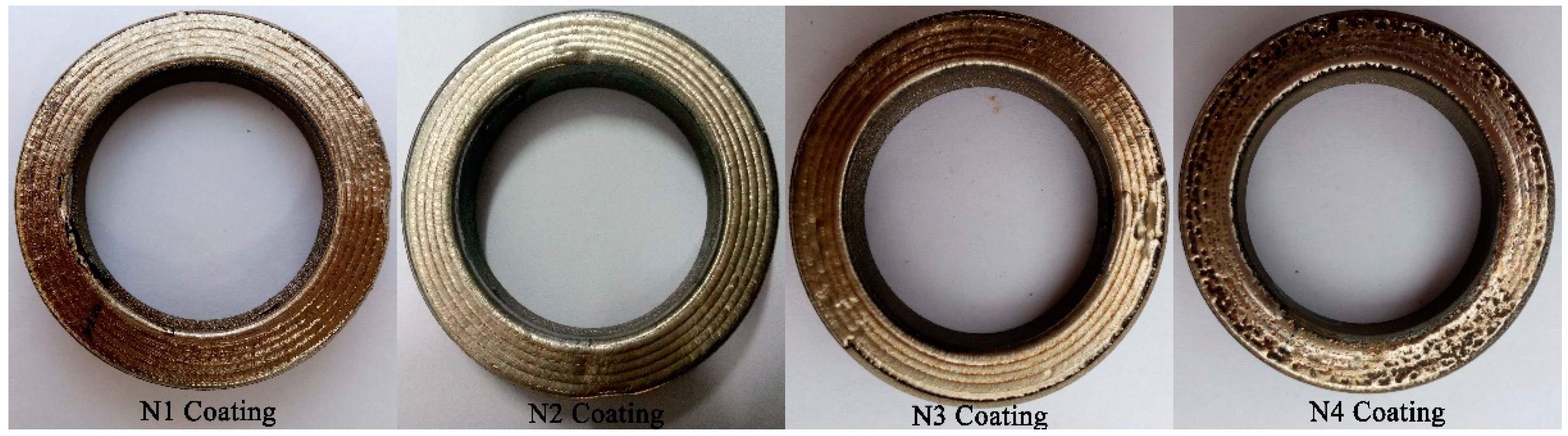
Figure 3.
Cross-sectional morphology of the plasma spray coating.
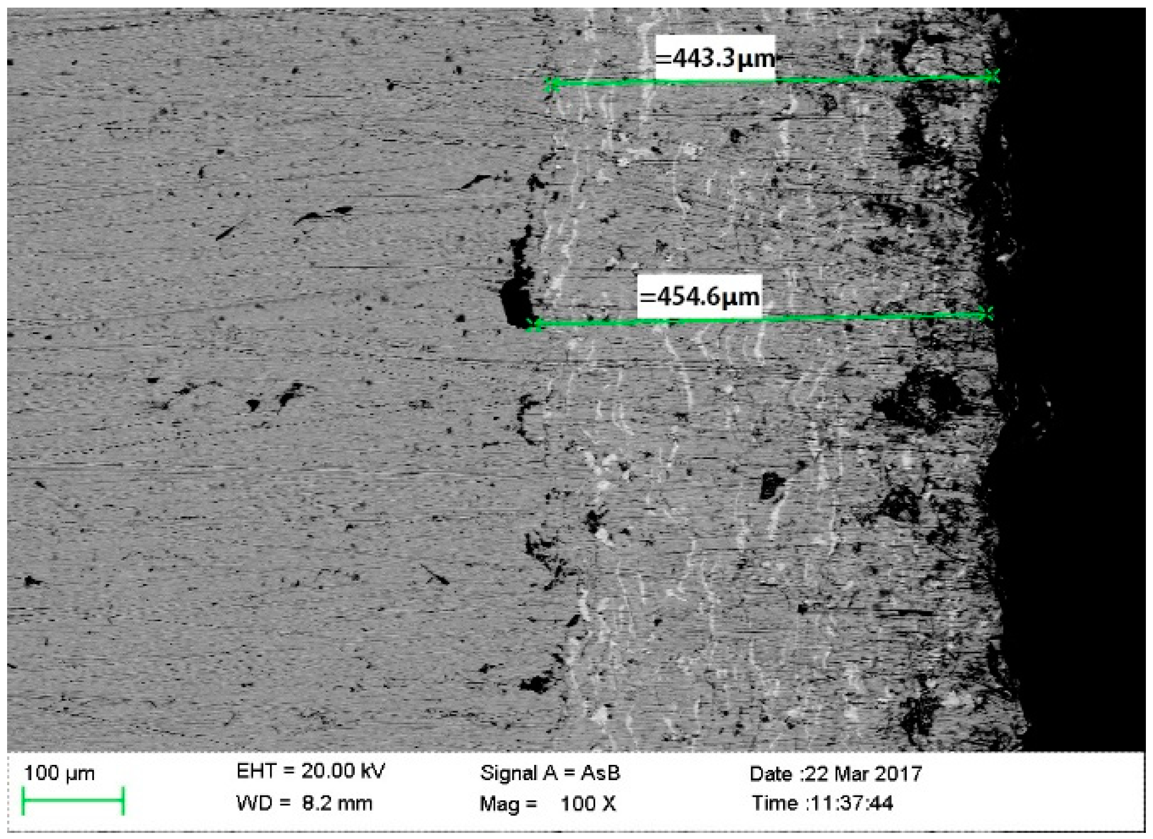
Figure 4.
Cross-sectional SEM micrographs: (a) N1 coating; (b) N2 coating; (c) N3 coating; (d) N4 coating; (a’–d’): metallographic microstructure of cladding regions in the N1, N2, N3 and N4 coatings, respectively.
Figure 4.
Cross-sectional SEM micrographs: (a) N1 coating; (b) N2 coating; (c) N3 coating; (d) N4 coating; (a’–d’): metallographic microstructure of cladding regions in the N1, N2, N3 and N4 coatings, respectively.

Figure 5.
Cross-section elemental distribution of the coatings at a scanning speed of 50 mm·min−1. (a) Cross-section elemental scanning of 50 mm·min−1; (b) Element distribution scanning of 50 mm·min−1.
Figure 5.
Cross-section elemental distribution of the coatings at a scanning speed of 50 mm·min−1. (a) Cross-section elemental scanning of 50 mm·min−1; (b) Element distribution scanning of 50 mm·min−1.

Figure 6.
Microhardness of the laser-remelted coatings.

Figure 7.
Friction coefficients of laser-remelted coatings at different laser scanning speeds.

Figure 8.
Wear rates of coatings at different laser scanning speeds.

Figure 9.
XRD patterns of wear surface of laser-remelted layers at different scanning speeds.

Figure 10.
Worn surfaces of coatings: (a) N1 coating; (b) N2 coating; (c) N3 coating; (d) N4 coating; (e) The pit on the N4 Coating.
Figure 10.
Worn surfaces of coatings: (a) N1 coating; (b) N2 coating; (c) N3 coating; (d) N4 coating; (e) The pit on the N4 Coating.

Figure 11.
Surface morphology of laser-remelted coatings: (a) 200 mm·min−1 scanning speed; (b) 100 mm·min−1 scanning speed.
Figure 11.
Surface morphology of laser-remelted coatings: (a) 200 mm·min−1 scanning speed; (b) 100 mm·min−1 scanning speed.

Figure 12.
Simple adhesion wear model.


Table 1.
Chemical composition of the iron-based alloy powder (wt. %).
| Ni | Cr | B | Si | C | Fe |
|---|---|---|---|---|---|
| 8–12 | 15–20 | 1.5–3 | 1.5–3 | <0.5 | Bal. |
Table 2.
Chemical composition of the Ni-based WC alloy powder (wt. %).
| Cr | B | Si | C | Fe | WC | Ni |
|---|---|---|---|---|---|---|
| 15–20 | 3.0–4.5 | 3.5–5.5 | 0.5–1.1 | ≤10 | 35 | Bal. |
Table 3.
Parameters used in the atmospheric plasma spraying.
| Parameters | Values Set |
|---|---|
| Spray distance | 100 mm |
| Powder delivery rate | 100 g·min−1 |
| Powder flow rate | 25 scfh |
| Voltage | 140 V |
| Current | 370 A |
| Primary air | 150 L·h−1 |
Table 4.
Experimental parameters of wear.
| Parameter | Value |
|---|---|
| Normal load | 400 N |
| Rotational speed | 200 r·min−1 |
| Wear time | 30 min |
| Temperature | 25 °C |
© 2018 by the authors. Licensee MDPI, Basel, Switzerland. This article is an open access article distributed under the terms and conditions of the Creative Commons Attribution (CC BY) license (http://creativecommons.org/licenses/by/4.0/).
Share and Cite
MDPI and ACS Style
Zhao, Y.; Du, H. Effect of Laser Scanning Speed on the Wear Behavior of Nano-SiC-Modified Fe/WC Composite Coatings by Laser Remelting. Coatings 2018, 8, 241. https://doi.org/10.3390/coatings8070241
AMA Style
Zhao Y, Du H. Effect of Laser Scanning Speed on the Wear Behavior of Nano-SiC-Modified Fe/WC Composite Coatings by Laser Remelting. Coatings. 2018; 8(7):241. https://doi.org/10.3390/coatings8070241
Chicago/Turabian StyleZhao, Yuncai, and Huihui Du. 2018. "Effect of Laser Scanning Speed on the Wear Behavior of Nano-SiC-Modified Fe/WC Composite Coatings by Laser Remelting" Coatings 8, no. 7: 241. https://doi.org/10.3390/coatings8070241
Note that from the first issue of 2016, this journal uses article numbers instead of page numbers. See further details here.