Editorial

To Do List for Research and Development and International Standardization to Achieve the Goal of Running a Majority of Electric Vehicles on Solar Energy

1
Toyota Technological Institute, Nagoya 468-8511, Japan
2
Underwriters Laboratories, Northbrook, IL 60062-2096, USA
3
Sunset Technology, Mount Airy, MD 21771, USA
*
Author to whom correspondence should be addressed.
Coatings 2018, 8(7), 251; https://doi.org/10.3390/coatings8070251
Submission received: 15 May 2018 / Revised: 2 June 2018 / Accepted: 13 July 2018 / Published: 17 July 2018
(This article belongs to the Special Issue Thin Film Solar Cells: Fabrication, Characterization and Applications)

Abstract

:
A car-roof photovoltaic has enormous potential to change our society. With this technology, 70% of a car can run on the solar energy collected by the solar panel on its roof. Unfortunately, it is not a simple extension of conventional photovoltaic technology. This paper lists what we need to do to achieve the goal of running a majority of cars on renewable solar energy, after clarification of the difference to conventional photovoltaic technology. In addition to technological development, standardization will be important and this list was made highlighting standardization.

1. Introduction

We may see a significant increase in a surprising combination of PV (photovoltaic) and passenger cars. The recent development of EV (Electric vehicle) and PHV (Plug-in hybrid vehicle) related automobile technology opens the door to the “solar-engine car”. When this happens, or to make it real, car-roof PV should not be blue-black, but vivid colors are often seen in the car body. Coating technologies and their application to PV technologies will be game-changing and a key technology for sound sustainability. It may be a dream right now, but it is worth taking on the challenge. In this article, the R&D to do list for game-changing car-roof PV technology is discussed.

2. Clarification of the Technologies, the Difference from Conventional PV Technologies

Before discussing the to do list for the realization of car-roof PV technologies, it is important to clarify why new challenges will need to be met, namely why this technology is not simply an extension of the current photovoltaic technologies.

2.1. Background of Car-Roof PV Development

Many automobile manufacturers have considered the use of PV as an energy source for passenger cars. Ford Motor presented a concept car powered by PV at an exhibition in 2014 [1]. It used CPV (Concentrator Photovoltaic) technology to enhance battery charge during parking. Toyota Motor started to sell a plug-in hybrid vehicle (PHV) with a 180 W solar panel made by Panasonic that expected to contribute to the energy source for the car engine in 2016 [2]. This movement was observed in other car companies in 2016, including Fisker Karma [3], Hanergy [4], Sono Motors [5,6], and Stella Lux [7]. Nissan, known as a major supplier of electric vehicles (EVs), mentions the necessity of charging-free EV, such as solar EV, to reduce the inconvenience of charging [8]. Now, PV is becoming recognized as one of the future energy sources for automobiles.
Masuda et al. experimented with installing a PV panel on the car body and monitored the energy generation [9]. The measured data implied the possibility that cars running less than 30 km/day may rely on the solar energy without the necessity to charge with electricity and gas [9]. It is expected to replace more than 60% of passenger cars and contributes to a significant cut in greenhouse gas emissions [9]. After this report, NEDO (New Energy and Industrial Technology Development Organization), issued an investigation report by the committee of a group of experts from think tanks, car-manufacturers, photovoltaic manufacturers and scientists from car-engineering and photovoltaic-engineering, and confirmed that 70% of a passenger car can run on solar energy using a realistic assumption [10]. Table 1 summarizes the assumptions used by two references.
As listed in Table 1, it is essential to consider the additional losses to evaluate the advantage of the car-roof PV. The mismatching loss among solar cell strings (not considered in Table 1) and the difference of solar irradiance was investigated by several other research papers [11,12,13,14].
The estimation of the ratio of the solar-driven passenger car varies by area, irradiation conditions, driving patterns, and average driving range. Nowadays, the irradiation conditions for the photovoltaic have become easy to access through various databases and web services, including modeling by satellite-based estimation [15,16,17], ground observation [17], in combination with weather forecasts [18]. However, it is important to note that the irradiation onto the car-roof and the car-body is different to that of typical solar panels. This issue will be discussed later in this paper.
The advantage to the user of the car-roof PV depends on driving patterns, and NEDO did an intensive investigation on that [10]. IEA PVPS started a new task (Task 17) to investigate this issue globally [19]. The average driving range relative to the irradiance is an excellent indicator for each country to estimate the rough advantage of solar-driven cars. Governments publish various statistics. An exciting and scientific approach in China is the use of GPS [20].
Based on this investigation, the market size and impact on our society can be estimated. The International Organization of Motor Vehicle Manufacturers (OICA) reported that the total sales of passenger cars in the world in 2017 was 71 million, precisely, 70,849,466—a 2% increase from the year of 2016 [21]. The requirement of the capacity of the car-roof photovoltaic modules is 1 kW per car [10]. The potential for the number of passenger cars that can run only on the solar energy will be 70% [10]. Therefore, the potential of the annual world market size can be calculated as 7.1 × 10⁷/year × 1 kW × 70% ≈ 50 GW/year. Note that this number did not consider the possibility of market growth in passenger cars, and it does not include other types of cars. Thus, it is not an over-optimistic scenario.
The market will not be limited to the passenger car. A project in Europe and USA demonstrated PV panels on trucks and succeeded in demonstrating an energy saving [22]. Although solar energy was not intended to be the exclusive energy supply, we may expect the substantial additional market for trucks and other types of cars.
Both Masuda et al. and NEDO calculated the amount of suppression of greenhouse gas emissions [9,10]. Masuda et al. estimated 32% reduction from the transportation section in Japan [9]. NEDO estimated 11% of the quota for automobiles (dependent on the scenario) [10]. Kimura et al. estimated 12% more than that of HV [23]. Although the scenario and the base figures were different, as shown in Table 1, the introduction of the car-roof PV will significantly cut the well-to-wheel greenhouse gas emissions by automobiles.

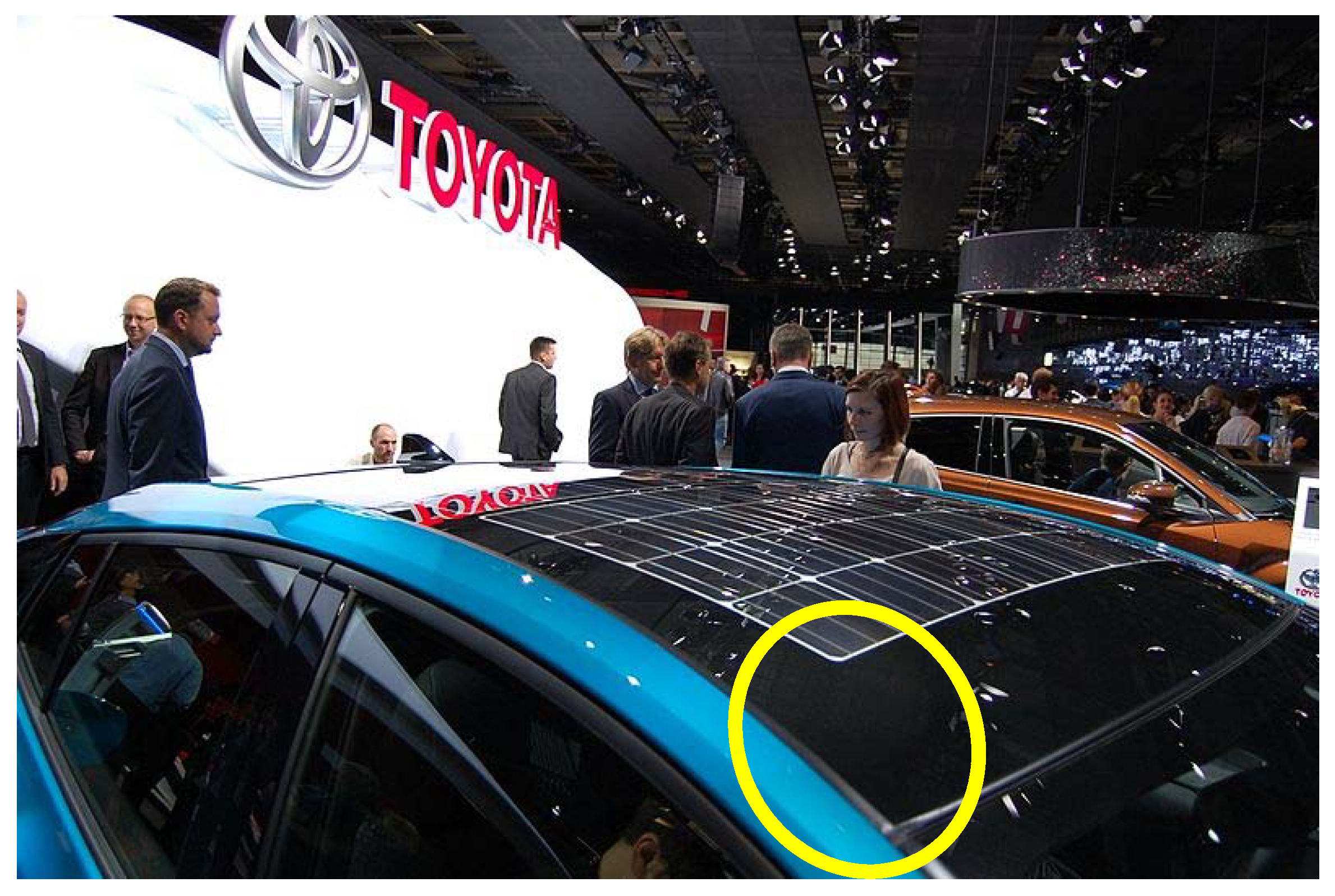
2.2. The New Value in Appearance

Another consideration is that the PV panel on the car-roof may be looked at closely and carefully. Most car customers may hate the exotic appearance of the PV module and PV cells. Since cars relying on solar energy may prevail to 70% of total passenger cars, it is hard to expect customers will accept the current PV modules as a car component. Ideally, the color of the PV panel will be identical to the color of the car body. At the same time, any additional color hampers the light absorption by the solar cell, and thus hampers the energy conversion performance. The development of color control technologies of PV modules with minimum suppression of the photovoltaic performance, but the realization of the fine color suitable to the car body, is vitally important.
Recently, the color control technologies of photovoltaic modules show significant progress, including addition of a print interlayer to the module [24], printing a ceramic layer on the front glass, using a front glass but adds a multilayered coating to generate the color [25], varying the thickness of the antireflection coating of the cell, thereby tuning the color [26], using multilayers on the cell [27], nanoparticles on the cell that give the cell a nice color [28], and inserting a foil with a uniform or graphical print [29,30,31]. Even the colored graphic can be added using back contact foil [24,32].
For emerging thin-film and organic solar cells, wide varieties of coloring techniques have been reported, including the use of dyes [33], applying colloidal quantum dots [34], adding photonic filters [35,36], integration with liquid/photonic crystals [37,38], using dielectric mirrors and optical microcavities [39,40], and modifying top or bottom electrodes [41,42].
A promising technology is using an automotive coating technology [43,44] with some apparent advantages of durability, ease of integration of mass productive solar cell or module technologies, color variations, and the ease of large-area painting. The advanced coating and color control of photovoltaic modules is also developed in Building-Integrated Photovoltaic (BIPV) [45,46].
It is important to note that any additional color coating for better appearance of the car-roof PV will lose output energy. It is important to develop practical and robust coating technology with minimum power generation loss while keeping the quality of the color appearance and a variety of colors. It is important to note the fact that roughly 40,000 automobile colors are already used today, and about 1000 colors are added to the list each year [46].
The shape of the car-roof is three-dimensionally curved. However, both the PV panel and solar cells are flat and rigid. It is not a good marketing strategy to change the shape of the car body to fit the standard PV panel, like a box consisting of flat plates.
Some commercial cars like the Solar-Prius of Toyota Motor and the products of Sono Motors place crystalline Si solar cells on the curved surface. However, they do not entirely cover the curved surfaces. The area where the radius of curvature is small was not filled by the solar cells (Figure 1). In this case, they are forced to place the solar cells in the high curvature area; it will often be cracked in either the solar cell or the interconnects.
For coverage of the curved surface, a suitable candidate may be a flexible and thin-film PV module. It is relatively easy to cover the two-dimensionally curved surface like toroidal surface. However, it is difficult to cover a three-dimensionally curved surface like a spherical surface. Accepting some gaps will be necessary to cover three-dimensionally curved surfaces with solar cells or thin-film photovoltaic, a possible solution is a static concentrator module [9,48,49,50,51].
It is important to note that a three-dimensional curved surface always reduces the projected area of the PV module, and reduces the absorption of solar energy. Additionally, the three-dimensionally curved surface has a self-shading effect and increases the mismatching loss among the solar cell strings. This three-dimensionally oriented photovoltaic loss is an essential factor to rating the car-roof PV module. This issue will be discussed later in this paper.

2.3. High Performance Required for Car Engines

High performance is the most critical requirement of the car-roof PV due to the energy source being constrained by solar irradiance and the limited space of the car-roof. It is important to note that the electrical energy output is a function of the utilization of the solar energy and the performance of the solar cell. Both factors are equally important. In other words, if the solar panel mounted on the car does not have high performance, the car will not use sufficient energy, even if the solar utilization and energy management are well-designed. If the system and the module are not designed well, the solar energy will be disappointing even though the car is equipped with high-performance solar cells. Figure 2 illustrates the difference in the irradiance environments of the car-roof from an exact horizontal plane. Because of the differences, the best PV module on the conventional utility market may not always perform well on the car-roof. However, the required solar cell efficiency or module efficiency is always a good indicator for the selection of a car-roof PV.
The available solar energy is proportional to the area of the car-roof, and it is limited. For securing sufficient energy with a limited area, high efficiency will be required at first to the car-roof PV product (Figure 3). Roughly speaking, 30% efficiency, 3 m2 of available area for the PV on the car, and 1 kW performance are required for car-roof PV [10].
Apparently, it is not an easy requirement of the solar cell with the current technology. The required 30% is above the theoretical limit of the most-common crystalline Si solar cells. The potential of the possible efficiency (standard testing condition) of various semiconductor materials like Silicon, III-V, CIS, CdTe, Organic, Dye-sensitized and Perovskite differs by the level of available crystal quality, point defects, dislocations, and interface recombination affects the potentials of the solar cell efficiency. Investigation of the efficiency potential of various types of solar cells was done by interviewing experts in each category of the semiconductor materials used in solar cells, about the practical limit of ERE (External radiation efficiency) considering the possibility of improving threading dislocation density and other crystal qualities [53,54]. The result is summarized in Table 2.
It is important to note that most types of solar cell have already reached 90% of the potential values with the efforts of scientists and engineers working in each category. It is also true that only multijunction cells can possibly exceed the 30% wall of efficiency. The problem is III-V multijunction cells are expensive and are commonly used in high concentrator photovoltaic applications. Development of a low-cost process is required.
A recent study estimated that the production cost of the III-V multijunction cell on Si cell is expected to be $0.85 $/W after achieving 1 GW/year of production [55]. The estimated cost is the same level of the production costs of the high-performance crystalline Si solar cells, but it is higher than that of the middle-grade crystalline Si cells. Masuda et al. proposed a static low concentrator module for reduction in the usage of the III-V multi-junction cells and thus reduction of the module cost [9].

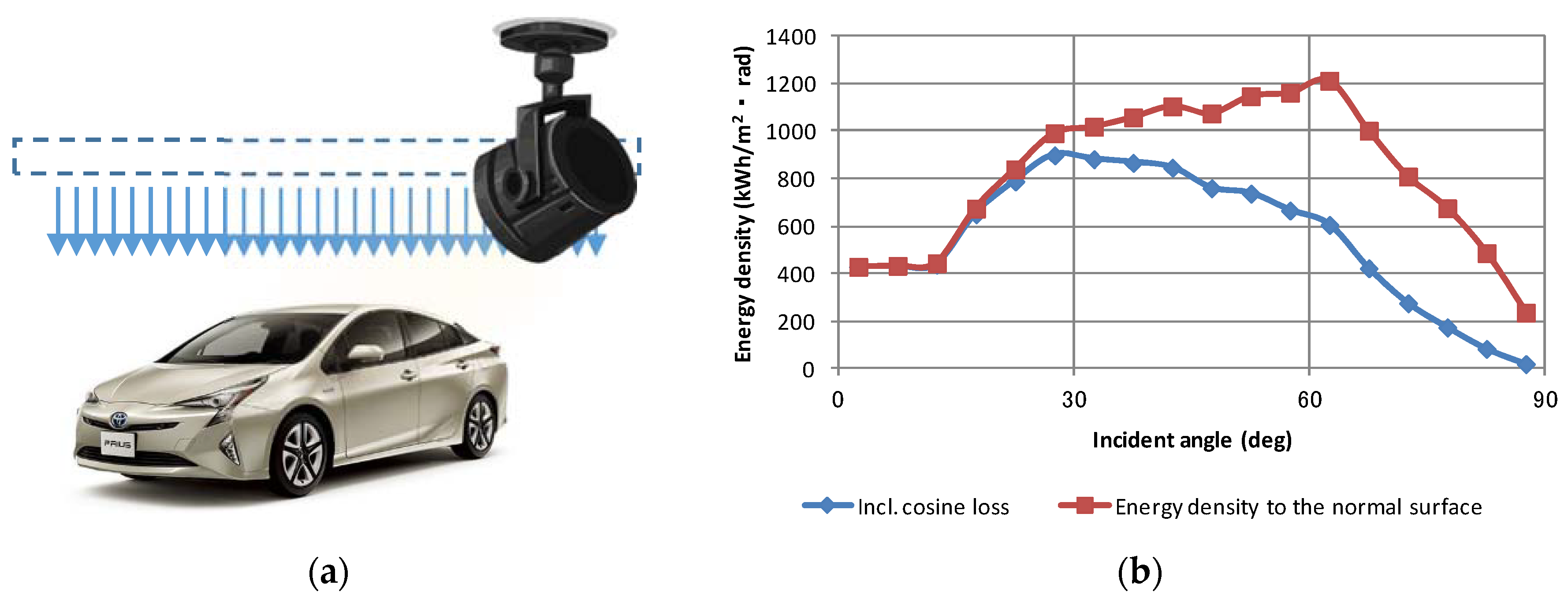
2.4. The Difference in Performance Modeling and Characterization

Unlike the PV panels either on the roof of residential houses or ground installation, the PV panel for automobile installation has a three-dimensionally curved surface like the “Solar Prius PHV” that Toyota Motor started selling in 2016. Currently, the typical interest of the car-owners of the car-roof PV is saving on gas and electric charges. Therefore, the efficiency of the PV panel and the management of the solar energy on the car-roof are not critical to the drivers. They will be satisfied if the PV panel fills the battery to some extent during parking. However, when the car mounts 1 kW car-roof PV panels, and the solar energy exclusively drives the cars, the efficiency rating and energy prediction will be critical.
For the modeling work and standardization of the energy generation of the car-roof PV, it is essential to define a meaningful and scientifically accurate method for the solar irradiance as well as its conversion to electricity on the three-dimensionally curved surface of the car-roof. First, it is critical to recognize that the solar irradiation onto the car-roof and the car-body will be different from that on the standard installations of PV panels. In principle, the traditional PV panels are installed so that they avoid shadows from other structures. However, the car-roof PV modules are not orientated for the utilization of solar energy, and the driver’s convenience often shades the panel. Second, the relative orientation of the PV panels on the car to the sun position is not fixed but frequently changes by driving. Third, the PV panels on the car body and the car roof are often three-dimensionally curved. It often shaded by its curved surfaces. Therefore, the essential value of the product, namely the scale of performance needs to be reconstructed from the beginning (Figure 4).
Faiman et al. [62] first introduced the recognition of three-dimensional irradiance and its modeling using multiple pyranometers placed on a different axis in 1993. Later, Baltazar et al. [63] improved the model and the measuring procedure for monitoring and modeling solar irradiance without relying on a tracker to collect the direct beam. For application to modeling the three-dimensional irradiation onto a three-dimensionally curved PV panel on a car-roof, it was essential to consider the following car-specific issues.
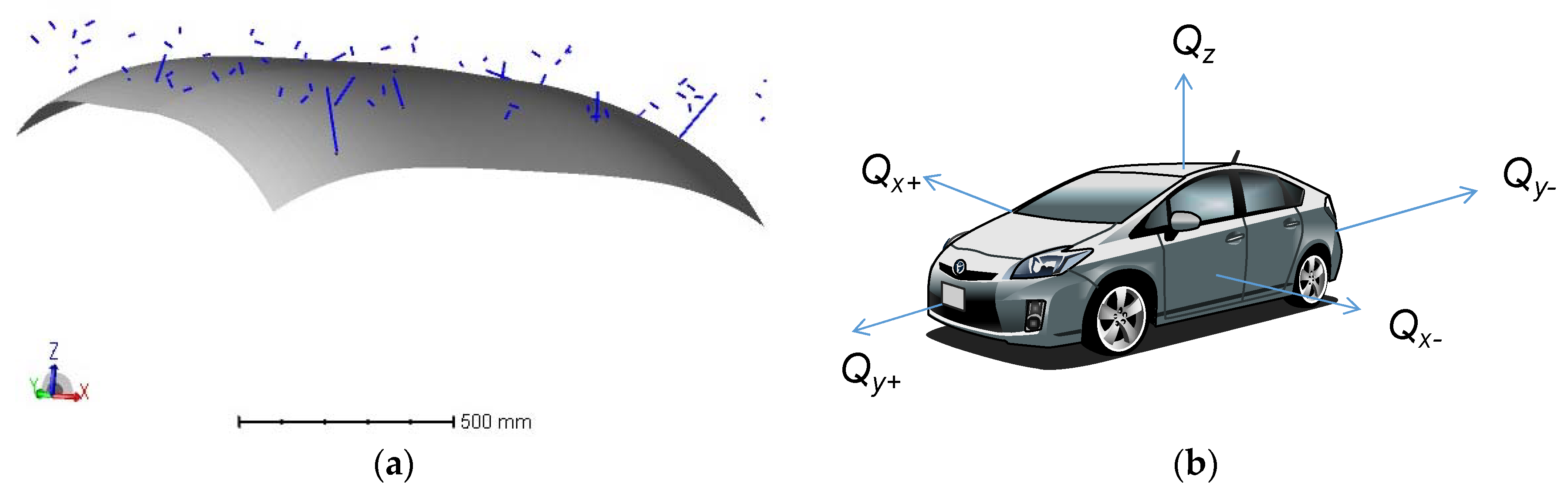
  • The axis is local to the car. Namely, they move by the movement of the car, and it is independent of the azimuth orientation. However, the relative position is unchanged and thus a linear coordinate conversion dynamically synchronized to the position, direction, and speed of the car, monitored by a GPS system, can handle this situation.
  • In principle, the coordinate is orthogonal. The model of Baltazar et al. [63] was not.
Figure 4 illustrates the three-dimensional recognition of the solar irradiance and its utilization by the three-dimensional curved surface of the PV module. Unfortunately, the pyranometer was mounted only in the horizontal position, and three-dimensional irradiance information was not collected during the project monitoring trucks traveling in Europe and the USA in 2016 [21].
Supposing that the orientation of the vehicle is random and independent of the sun’s position, the standard irradiance parameters and the local irradiance parameters of the car-body can be converted to the following nine equations [64,65]. Note that the inclination of the vehicle body was ignored. Some functions and equations contain Boolean operations, and they return 1 or zero depending on whether the operation results are true or false.
Q r o o f = Q Z
Q s i d e = Q X + + Q X + Q Y + + Q Y 4
Φ = if ( Q Z > Q t h , tan 1 ( | max ( Q X + , Q X ) max ( Q Y + , Q Y ) | Q Z ) , N a N )
D = if ( min ( Q X + , Q X ) + min ( Q Y + , Q Y ) < Q s i d e , Q Z > Q t h , 0 )
where Qroof is the irradiance onto the car-roof. Qside is the averaged irradiance of the sides of the car. Since the orientation of the car is supposed to be independent of the sun’s orientation, the side irradiation may be regarded as the averaged value from four sides. Φ is the main angle of the solar beam onto the car-roof. Qth is the threshold of the effective measurement value of the irradiance. It must be greater than zero (non-zero value). NaN represents a missing or faulted value. D is the discriminant of the non-shaded condition. False (=0) if the car-roof is shaded. The function if(condition, x, y) returns x if condition is true (non-zero), y otherwise. The function max(A, B, C, ...) returns the largest value from A, B, C, ... The function min(A, B, C, ...) returns the smallest value from A, B, C, ... Note that the Equation (3) contains two-dimensional vector calculation, and the Equation (4) contains the Boolean algebra.
The orientation angle of the principal solar beam, not always equal to the orientation angle of the direct beam, is calculated by the following equations.
Q S 1 = max ( Q X + , Q X , Q Y + , Q Y )
Q S 2 = max   2 nd ( Q X + , Q X , Q Y + , Q Y )
a x 1 = ( Q S 1 = Q X + ) π 2 + ( Q S 1 = Q Y ) π + ( Q S 1 = Q X ) 3 π 2
a x 2 = ( Q S 2 = Q X + ) π 2 + ( Q S 2 = Q Y ) π + ( Q S 2 = Q X ) 3 π 2
G = m o d ( if ( ( Q S 1 > Q t h s ) ( | a x 1 a x 2 | = π 2 ) , tan 1 ( Q S 2 Q S 1 ) s ign ( a x 2 a x 1 ) + a x 1 + D i r , N a N ) , 2 π )
where Qs1, Qs2, ax1, and ax2 are parameters calculated by Equations (5)–(8) and are used to Equation (9). G is the orientation angle of the main solar beam. Dir is the orientation angle of the car. The function max2nd(A, B, C, ...) returns the second largest value from A, B, C, ... The function mod(x, y) returns the remainder on dividing x by y (x modulo y). The result has the same sign as x. The function sign(x) returns 0 if x = 0, 1 if x > 0, and −1 otherwise. Note that Equations (7)–(9) contain Boolean algebra.
Using five pyranometers orthogonally mounted in the car (Figure 4b), and applying Equations (1)–(9) to the monitored irradiance data, the three-dimensional solar irradiance around the car may possibly be modeled. For the rating of the three-dimensionally curved module (Figure 4a), the most practical approach may be an introduction of the curve-correction factor. The curve correction factor is a unique value depending on the three-dimensionally curved shape of the PV module as well as the three-dimensional solar irradiance. In the case of the curved surface shown in Figure 4a, it was calculated as 0.78. Namely, the three-dimensionally curved module in Figure 4a will utilize the solar resource only to 78% of the one on the horizontally placed flat-plate. The influence of the three-dimensional curve on the energy generation cannot be ignored. A detailed description of how to rate the three-dimensionally curved module will be discussed later in this paper.

2.5. The Difference in the Utilization of Solar Energy

When the passenger car relies on solar energy, energy administration will be crucial. It will be needed to combine map data, the image around the car (shading prediction), and irradiation forecasts. The issue is the accurate prediction of the irradiation onto the car. The required prediction technologies will be different from the typical weather and solar-resource prediction technologies (Table 3). Comparison of the required solar resource prediction technology form conventional techniques.
Considering the required efficiency, it is likely that the solar cells used in the car-roof photovoltaic module may be multi-junction cells (Table 2). It is well-known that the multi-junction cells are sensitive to the variation of the solar spectrum. Advanced and precise prediction of the solar spectrum at least considering a variation of the atmospheric parameters will be necessary [65].
The driving test in the past experiment on the PV panel mounted on the car done by Masuda et al. [9] and Schuss et al. [14,16] revealed a substantial loss by the current and voltage mismatching among the solar cell strings, coming from partial shading and the angle between the solar beam and the orientation of the string. It may be improved by the string design or the introduction of a DC voltage boosting device in the module for compensating the mismatching. It is also an essential aspect of rating the module and its standardization. This issue will be discussed later in this paper.

2.6. Need for New Standardization

The fact that the car-roof PV uses the three-dimensional solar resource by the three-dimensionally curved photovoltaic module means that the standard rating and testing method may not lead to the appropriate values. The possible testing method has been discussed among experts including scientists and engineers in testing laboratories. Figure 5 depicts a possible method using a mixture of light sources representing diffused sunlight and direct sunlight.
Traditionally, the car manufacturers test components in many aspects of the car-specific conditions. Some of them are not the tests commonly done in the PV panel. We are investigating the car-specific components tests and relate them to the PV tests. The most closed type of the components are car-electronics and exterior components. Table 4 summarizes the comparison between the car-electronics and the PV. Note there are some differences.

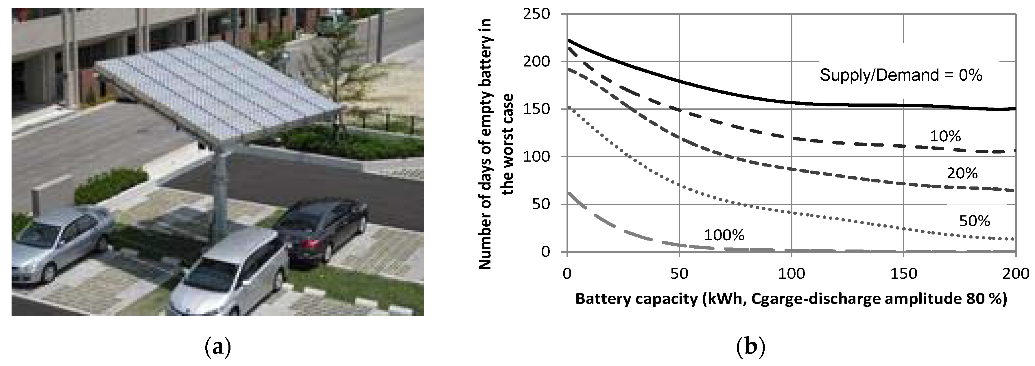
2.7. Related Technologies Out of the Car

When most EVs run on solar energy, smart-control of solar energy will be demanded (Figure 6) [65].
To construct an energy administration system and related services, the core technology is the precise modeling of the energy generation of the car-roof, including spectrum prediction. In addition to the hardware, infrastructure and system integration, a precise but quick calculation method of energy prediction that was discussed in the previous section and in Table 3 will be critical.
Depending on driving patterns, there may be a possibility that the car-battery becomes full or empty. Then, circulation of the car-generated solar energy will be critical. One possibility is the infrastructure of the solar EV station that supplies electricity from pure solar energy and accepts surplus solar energy from visiting cars (Figure 7). The operation of this system will be effective combined with a smart energy administration system (Figure 7). For optimum and economic system design, a Monte Carlo method will be effective [49,66].
Time spent parked is longer than time spent driving for most passenger cars. Collection of solar energy is as important as driving. The value of the shadow by the garage will vary. One possibility is that the garage roof may be tracking photovoltaic to collect solar energy efficiently and simultaneously partially illuminates the car-roof by the sunlight from the edge of the moving panel (Figure 8). The prediction of the solar illumination under the panel was analyzed for the hybrid photovoltaic system for agriculture, but this approach can be applied to the garage design for solar-driven EVs [67].

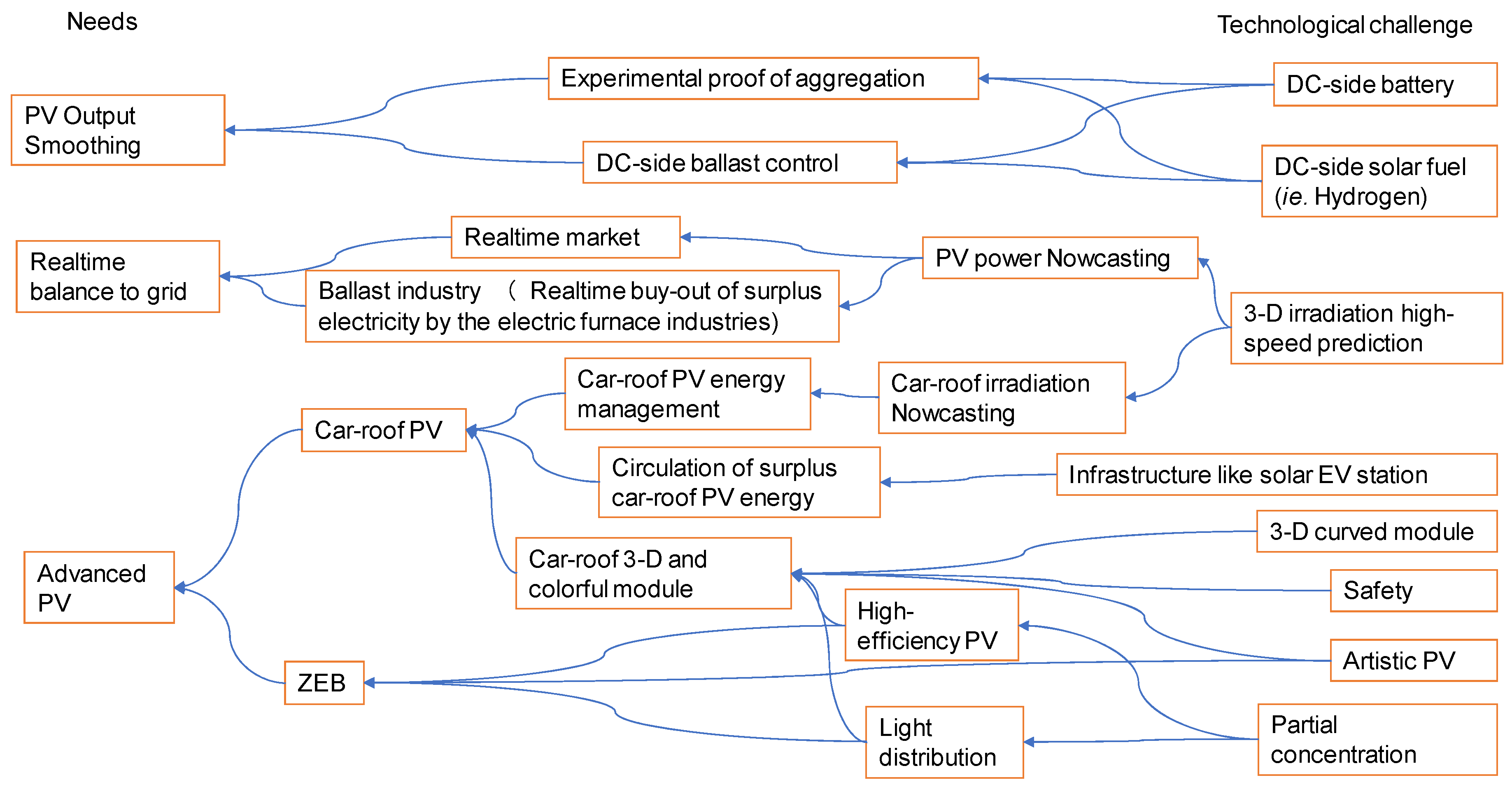
3. Discussion—Impact on All PV Technologies

With the effort of developing technology for car-roof irradiation prediction, which is necessary for the car-energy management system, the severe challenge to the solar energy prediction of the three-dimensional and moving coordinates will create the opportunity to improve the accuracy of PV energy prediction and thus leads to the establishment of the real-time market for PV surplus energy.
Besides three-dimensional irradiation issues, the R&D of car-roof PV technology has many other ripple effects. The massive new market and its impact on society will have sufficient power to change the technology environment (Figure 9).
For example, car-roof PV technology has many similarities to PV and ZEB (zero-emission building) technologies. Many technological challenges for car-roof PV will help to solve problems in PV integration with buildings. The power-conversion technology in the car will be useful for developing a DC-side PV energy buffer. The realization of the real-time market backed by precise energy nowcasting will create a new industry (ballast industry), mainly by the electric furnace industries for smoothing PV impact to the grid.

4. Conclusions—List of To Dos

The to do list for the technology aspect is simple. It is the research and development that was clarified in the previous section. On the contrary, for standardization of the technology, we needed to discuss among scientists, engineers in manufactures, engineers in testing laboratories, and experts in related organizations. After recognition and clarification of the difference from conventional PV technologies, the list of to dos was discussed by a group of scientists and engineers (see the acknowledgment section for detailed information of the group).

4.1. Rating Tests

The following questions need to be resolved before the performance evaluation.

4.1.1. Definition of the Standard Irradiation for Testing the Car-Roof Photovoltaic Products

  • Orientation/declination of the artificial collimated light mimicking the direct solar irradiation onto the car-roof;
  • Is it sufficient to represent the direct beam of the sunlight by a single angle of the light? Do we need to prepare multiple collimated lights to represent various levels of the sun height?
  • The standard value of the ratio of (the diffused sunlight)/(the direct sunlight).

4.1.2. Definition of the Standard Irradiation

  • Definition of the standard illumination, including spectrum, irradiance, the ratio of the collimated component to the diffused component, size of the light source relative to the photovoltaic module, and angular distribution;
  • Size of the diffused source relative to the size of the car-roof PV. The diffused light source contains rays with a low angle and the car-roof PV may not absorb such rays unless the size of the light source is large enough;
  • Height of the diffused source from the car-roof PV. Since the size of the diffused light source is finite, the distance from the light source affects the measurement conditions;
  • Spotlights may be used as the collimated light source, representing the direct component of the sunlight. The specification of the collimation is needed;
  • Since the size of the spotlight is limited, it is likely smaller than the car-roof panel area. Multiple spotlights may be necessary but we need to decide the specifications and requirements of the spot-light array;
  • It is likely that the car-roof photovoltaic may be the spectral-sensitive multi-junction solar cells. For reasonable spectral representation, a cocktail of multiple lamps will be necessary. The solar simulators using a cocktail lamp are already commercialized but they need to be upgraded with additional control of diffused/direct ratio and angular distribution.

4.1.3. Specification of the Light Source and the Testing Room

  • A detailed procedure needs to be prepared;
  • The color of the wall/floor/ceiling of the testing room may affect the measurement. Considering that the car-roof PV product may have cosmetics of the controlled color coatings, it is crucial to quantify the influence of the color of the testing room. Note that the car-roof PV is used at a relatively higher ratio of the diffused sunlight and that diffused light is affected by the color of the room through wall/floor/ceiling reflections;
  • Is a car-fixture needed (same color)? Fixtures may solve the color issue problems.

4.1.4. Miscellaneous

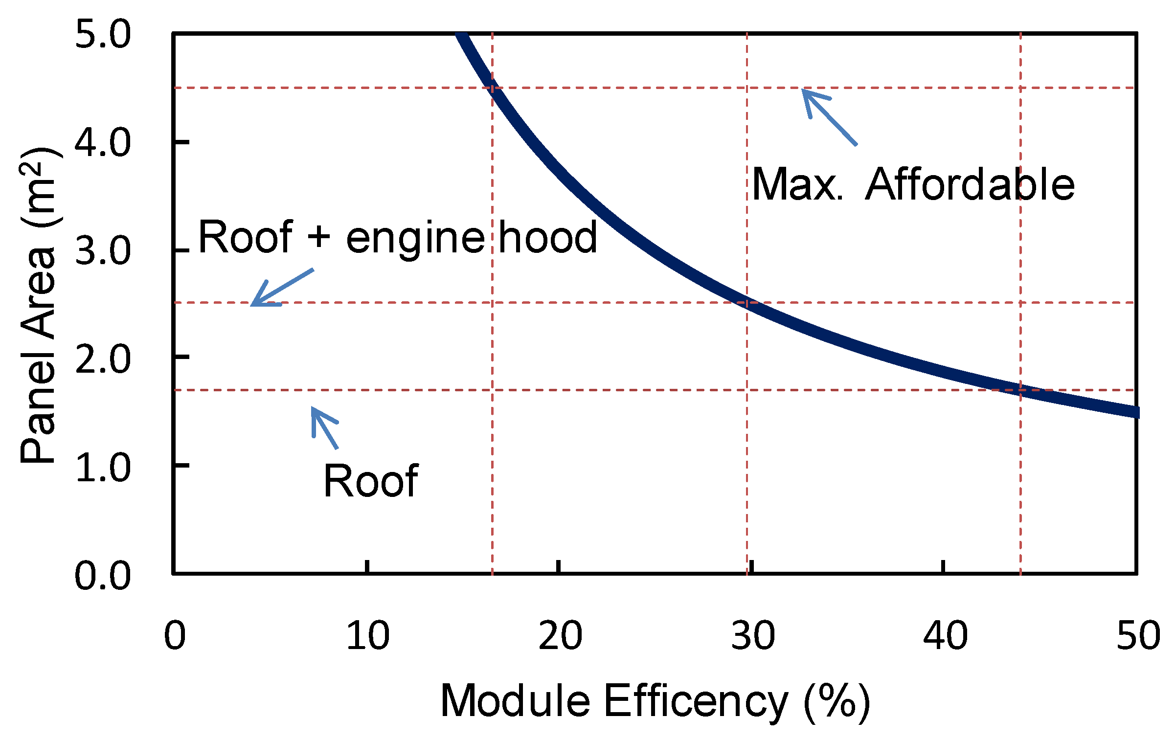
  • The PV for passenger cars is not only loaded on the car-roof. How about the door, and engine hood? When this happens, can we apply the same testing conditions?
  • The temperature of the standard testing condition (indoors) is 25 °C. Is it an appropriate testing condition for the car-roof PV? Do we need to increase the temperature, for example, to 60 °C?
  • Is the flexible PV tested before mounting or after mounting? The shape of the photovoltaic panel changes after mounting on the car. The panel shape affects the photovoltaic performance.

4.2. Design Qualification

The following questions need to be resolved before the qualifying the design:

4.2.1. Environmental Tests

  • List of the testing items and their conditions. Preferably with pass/fail criteria.
  • The necessity of car-specific tests including weight, dimensions, aerodynamics, safety, robustness to car-wash, and so forth.

4.2.2. Requirements for Qualification

  • Definition of the minimum requirement and its background;
  • Label, specification sheet, and its required item list;
  • Retest guideline, namely when the car-roof PV undergoes a minor design change to fit a new or customized car design, what kind of retest items need to be required to keep qualification recognition?
  • Range of resembles as the criteria for the necessity of retests;
  • Who is the testing certification body? Are they controlled by IECEE (IEC System of Conformity Assessment Schemes for Electrotechnical Equipment and Components)?

4.2.3. Miscellaneous

  • List and definition of terms;
  • Specification of the car-interface like cables and connectors.

4.3. Power Modeling

The following points are to do list for the development of power-generation modeling of the car-roof PV. Note that there are opinions that this issue is out of the standardization.

4.3.1. Modeling Work

  • Simplified parameter (Curve correction): Full three-dimensional parameters may not be intuitive and thus difficult to understand for most of the engineers who are accustomed to working on photovoltaic with two-dimensional parameters. A kind of a correction factor, for example, a curve correction coefficient will be helpful. This parameter should be identical to the curve shape;
  • Modeling by rigorous calculation: For the development of solid modeling, the parameter measurement and the representation of the standard operating conditions, some approximation will be necessary. To validate the approximated approach, rigorous modeling should be established as a benchmark of the research and development;
  • Interaction to the string orientation: Both output current and output power of the curved car-roof PV will not be proportional to the absorbed irradiance. The mismatching loss among strings that is not significant in a conventional photovoltaic module, unless it is partially shaded, will be significant to car-roof PV. Inherently, it will make a variation of the cosine loss and the self-shaded loss that enhance the mismatching loss among strings. The mismatching loss varies by the orientation of the string relative to the sun orientation;
  • Unit element vs. Shape calculation: Related to the above item, a direct extension from two-dimensional modeling that has been used in conventional PV is that the three-dimensionally curved surface is divided into many small unit elements, standard calculation is conducted and then computed from a surface integral. It is important to compare any curve-correction factors by this approach;
  • Curve-shape representation (for example, 90% angle): A three-dimensional CAD (Computer Aided Drawing) file may provide the three-dimensional curve profile of the car-roof. Thanks to the development of CAD/CAE (Computer Aided Engineering) technologies, it is not very difficult to do geometrical calculation directly from the CAD file. However, this procedure often concedes apparent problems because the geometrical information is often concealed in the Blackbox. An intuitive and practical parameter will be helpful for understanding what is going on in the geometrical and modeling calculation;
  • Outdoor measurement validation: It should be done by multiple modes of operation, like various levels of latitude, climate shading (like rural or urban area);
  • Definition of a light-source model: For the development of the testing procedure discussed in the above section, the development of light source modeling will be necessary.

4.3.2. Parameter Measurement for Modeling

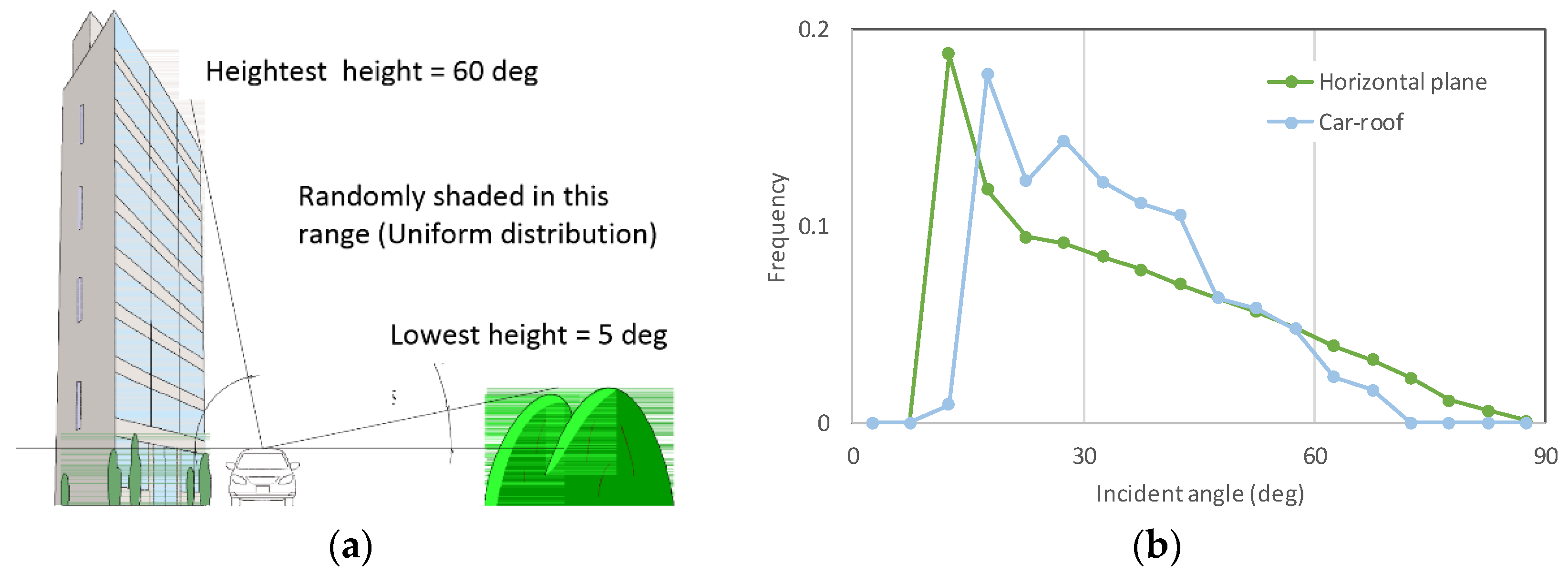
  • AOI (Angle of incidence) measurement: Since the car-roof PV collects three-dimensional sunlight, especially the rays from a high incident angle, AOI measurement will be crucial. Different from the conventional PV panels, the AOI characteristics are not axially symmetrical. It is not uniform at the position of the panel, because the curvature varies and the self-shading effect varies by the position of the car-roof panels;
  • Standard solar irradiation condition onto the car-roof;
  • PV fine color: It is likely that the advanced coating technology decorates the car-roof PV and shows a variety of colors like car-body paint. Impact of color variation needs to be intensively studied. The impact factor of the color should be defined in both physical background and detailed measurement procedures.

4.4. Energy Prediction

The following points are a to do list for the development of energy prediction of the car-roof PV. Note that there are opinions that this issue is out of the standardization.

4.4.1. kWh/kW, km/kW Issue

The most representative scale of the merit of the car-roof PV to users will be the running distance of the car with given performance, possibly rated by the nominal power of the photovoltaic module. The running distance is a function of the car energy efficiency and thus electrical energy per rated power, namely kWh/kW, may be an alternative scale for car-roof PV performance. The kWh/kW is primarily a function of “effective solar irradiance” and may not be identical to the irradiance conventionally used in the PV community.
  • Difference between GHI and car-roof PV: Possibly, the scale closest to normal solar irradiance may be GHI (Global Horizontal Irradiance). The quickest way is to clarify the difference from GHI both by modeling and measurement;
  • Power modeling vs. climate: Clarification of the quantitative difference of the power output influenced by climate and other meteorological conditions. Note that the generation on cloudy and rainy days will be equally crucial to the car-roof PV, unlike the conventional PV for utility;
  • Three-Dimensional solar modeling: Car-roof PV tries to collect solar energy not only from the normal directions. The module itself is three-dimensionally curved. Modeling solar irradiation by three-dimensional may be convenient.

4.4.2. Energy Nowcasting

Note that this item differs by the general system design. The most straightforward system may be the anticipation of the most-likely energy generation from the information on the energy generated by the surrounding cars through inter-car communication. If prediction by this method is accurate and robust enough, it will not be necessary to collect irradiance information.
  • High-speed calculation algorithm;
  • Link to the drive recorder image (dynamic shading);
  • The requirement of the dataset (item etc.);
  • Map integration.

4.4.3. Standard Smart Administration

Again, it depends on the system design.
  • Standard data format;
  • Standard procedure (using satellite?).

Author Contributions

Technology conceptualization and analysis, K.A.; Standardization conceptualization and analysis, L.J. and G.K.; Project Administration, M.Y.

Funding

This research was funded by The Japan Electrical Manufacturing Association (JEMA) and New Energy and Industrial Technology Development Organization (NEDO) under the Ministry of Economy, Trade and Industry (METI), Japan.

Acknowledgments

The activities of international standardization have been done by the voluntary contribution of engineers and scientists. Some of the active members with responsibility in some sub-areas are listed in the author list, but, it is apparent that many other contributors were involved behind the scenes. The preliminary discussion of formalization of three-dimensional sunshine irradiation and the rating of the continuously three-dimensional carved PV panel was started by a group consisting of 33 volunteer scientists and engineers from 11 countries including Japan, Korea, China, Australia, India, Germany, Italy, the Netherlands, Spain, the UK, and the USA as of 31 May 2018, from various groups including IEC TC82 WG2, IEC TC82 WG7, IEA PVPS Task17, and PVQAT TG8 with a good mixture of scientists, manufacturers, testing laboratories, and governments/organizations. International meeting sessions started in December 2017 using the web meeting system. As of 31 May 2018, we had five web meetings.

Conflicts of Interest

The authors declare no conflict of interest. The funding sponsors had no role in the design of the study; in the collection, analyses, or interpretation of data; in the writing of the manuscript, and in the decision to publish the results.

References

  1. The Ford Motor Company. Let the Sun In: Ford C-MAX Solar Energi Concept Goes Off the Grid, Gives Glimpse of Clean Vehicle Future. Available online: https://media.ford.com/content/fordmedia/fna/us/en/news/2014/01/02/let-the-sun-in--ford-c-max-solar-energi-concept-goes-off-the-gri.html (accessed on 9 May 2018).
  2. Automotive News, Next-Generation Toyota Prius Has Solar Roof for Europe, Japan. Available online: http://www.autonews.com/article/20160616/OEM05/160619900/next-generation-toyota-prius-has-solar-roof-for-europe-japan (accessed on 9 May 2018).
  3. Automotive News. Available online: http://www.autonews.com/article/20160811/OEM04/308119912/karma-targets-tesla-with-$115000-solar-boosted-hybrid (accessed on 9 May 2018).
  4. Hanergy Holding Group Ltd. Available online: https://www.autoevolution.com/news/china-s-hanergy-unveils-four-solar-powered-concept-cars-109094.html (accessed on 20 September 2016).
  5. Sono Motors. Available online: https://www.sonomotors.com/sion/#1 (accessed on 20 September 2016).
  6. Sono Motors Homepage. Available online: https://sonomotors.com/ (accessed on 9 May 2018).
  7. Solar Team Eindhoven. Available online: https://solarteameindhoven.nl/stella-vie/stella-lux/ (accessed on 9 May 2018).
  8. Nissan Motor Corporation. Nissan Sustainability Report 2014. Available online: http://www.nissan-global.com/EN/CSR/SR/2014/ (accessed on 9 May 2018).
  9. Masuda, T.; Araki, K.; Okumura, K.; Urabe, S.; Kudo, Y.; Kimura, K.; Nakado, T.; Sato, A.; Yamaguchi, M. Static concentrator photovoltaics for automotive applications. Sol. Energy 2017, 146, 523–531. [Google Scholar] [CrossRef]
  10. NEDO, Interim Report of the Exploratory Committee on the Automobile Using Photovoltaic System. Available online: http://www.nedo.go.jp/news/press/AA5_100909.html (accessed on 9 May 2018).
  11. Schuss, C.; Eichberger, B.; Rahkonen, T. A monitoring system for the use of solar energy in electric and hybrid electric vehicles. In Proceedings of the IEEE Instrumentation and Measurement Technology Conference (I2MTC), Graz, Austria, 13–16 May 2012; pp. 524–527. [Google Scholar]
  12. Schuss, C.; Gall, H.; Eberhart, K.; Illko, H.; Eichberger, B. Alignment and interconnection of photovoltaics on electric and hybrid electric vehicles. In Proceedings of the IEEE Instrumentation and Measurement Technology Conference (I2MTC); Montevideo, Uruguay, 12–15 May 2014; pp. 153–158. [Google Scholar]
  13. Schuss, C.; Kotikumpu, T.; Eichberger, B.; Rahkonen, T. Impact of dynamic environmental conditions on the output behaviour of photovoltaics. In Proceedings of the 20th IMEKO TC-4 International Symposium, Benevento, Italy, 15–19 September 2014; pp. 993–998. [Google Scholar]
  14. Schuss, C.; Eichberger, B.; Rahkonen, T. Impact of solar radiation on the output power of moving photovoltaic (PV) installations. In Proceedings of the IEEE Instrumentation and Measurement Technology Conference (I2MTC), Houston, TX, USA, 15–17 May 2018; pp. 1297–1302. [Google Scholar]
  15. Hammer, A.; Heinemann, D.; Hoyer, C.; Kuhlemann, R.; Lorenz, E.; Müller, R.; Beyer, H.C. Solar energy assessment using remote sensing technologies. Remote Sens. Environ. 2003, 86, 423–432. [Google Scholar] [CrossRef] [Green Version]
  16. Hammer, A.; Heinemann, D.; Lorenz, E.; Lückehe, B. Short-term forecasting of solar radiation: A statistical approach using satellite data. Sol. Energy 1999, 67, 139–150. [Google Scholar] [CrossRef]
  17. Itagaki, H.; Okumura, H.; Yamada, A. Preparation of meteorological data set throughout Japan for suitable design of PV systems Photovoltaic Energy Conversion. In Proceedings of the 3rd World Conference on Photovoltaic Energy Conversion, Osaka, Japan, 11–18 May 2003; Volume 2. [Google Scholar]
  18. Lorenz, E.; Hurka, J.; Heinemann, D.; Beyer, H.G. Irradiance forecasting for the power prediction of grid-connected photovoltaic systems. IEEE J. Sel. Top. Appl. Earth Obs. Remote Sens. 2009, 2, 2–10. [Google Scholar] [CrossRef]
  19. PV for Transport: A Logical Evolution. Available online: http://www.iea-pvps.org/index.php?id=267 (accessed on 30 May 2018).
  20. Wang, H.; Wu, L.; Hou, C.; Ouyang, M. A GPS-based research on driving range and patterns of private passenger vehicle in Beijing. In Proceedings of the 2013 World Electric Vehicle Symposium and Exhibition (EVS27), Barcelona, Spain, 17–20 November 2013. [Google Scholar]
  21. Provisional New PC Registrations or Sales, (Sales of New Vehicles 2005–2017), Statistics of International Organization of Motor Vehicle Manufacturers. Available online: http://www.oica.net/category/sales-statistics/ (accessed on 9 May 2018).
  22. Eitner, U.; Ebert, M.; Zech, T.; Schmid, C.; Watts, A.; Heinrich, M. Solar Potential on Commercial Trucks: Results of an Irradiance Measurement Campaign on 6 Trucks in Europe and USA. In Proceedings of the 28th EUPVSEC), Frankfurt, Germany, 30 September–4 October 2013; pp. 2147–2150. [Google Scholar]
  23. Kimura, K.; Kudo, Y.; Sato, A. Techno-Economic Analysis of Solar Hybrid Vehicles Part 1: Analysis of Solar Hybrid Vehicle Potential Considering Well-to-Wheel GHG Emissions; SAE Technical Paper; No. 2016-01-1287; SAE International: Warrendale, PA, USA, 2016. [Google Scholar]
  24. Slooff, L.H.; van Roosmalen, J.A.M.; Oke, L.A.G.; de Vries, T.; Minderhoud, T.; Gijzen, G.; Sepers, T.; Versluis, A.; Frumau, F.; Rietbergen, M.; et al. An Architectural Approach for Improving Aesthetics of PV. In Proceedings of the European PV Solar Energy Conference and Exhibition EU PVSEC, Amsterdam, The Netherlands, 25–29 September 2017. [Google Scholar]
  25. Kromatix™ by Swiss INSO. Available online: https://www.swissinso.com/ (accessed on 9 May 2018).
  26. LOF Solar Corp. Home Page. Available online: http://www.lofsolar.com/ (accessed on 9 May 2018).
  27. Selj, J.H.; Mongstad, T.T.; Søndenå, R.; Marstein, E.S. Reduction of optical losses in colored solar cells with multilayer antireflection coatings. Sol. Energy Mater. Sol. Cell 2011, 95, 2576–2582. [Google Scholar] [CrossRef]
  28. Neder, V.; Luxembourg, S.L.; Polman, A. Efficient colored silicon solar modules using integrated resonant dielectric nanoscatterers. Appl. Phys. Lett. 2017, 111, 073902. [Google Scholar] [CrossRef]
  29. SOLARSKIN Solar with Curb Appeal. Available online: https://www.sistinesolar.com/ (accessed on 9 May 2018).
  30. Kaleo. Available online: http://www.kaleo-solar.ch/fr/index.php (accessed on 9 May 2018).
  31. Rooms, H.C.A.; Barbu, I.; Vroon, Z.A.E.P.; Meertens, R.; Vermeulen, B. Multilayer front-sheet for solar modules with tuned color appearance. In Proceedings of the Thin Film Solar Technology III, San Diego, CA, USA, 21–22 August 2011. [Google Scholar]
  32. Lin, H.; Qui, Z.; Cao, K.; Zhao, L.; Chen, X.; Long, W.; Beaucarne, G.; Peng, W.; Chislea, B.; Yu, Y.; et al. Durable MWT PV modules made using silicone electrically conductive adhesive and an automated assembly line. Photovolt. Int. 2014, 23, 24–30. [Google Scholar]
  33. Broek, K.M.; Bennett, I.J.; Kloos, M.J.H.; Eerenstein, W. Cross testing electrically conductive adhesives and conductive back-sheets for the ECN back-contact cell and module technology. Energy Procedia 2015, 67, 175–184. [Google Scholar] [CrossRef]
  34. Arinze, E.S.; Qiu, B.; Palmquist, N.; Cheng, Y.; Lin, Y.; Nyirjesy, G.; Qian, G.; Thon, S.M. Color-tuned and transparent colloidal quantum dot solar cells via optimized multilayer interface. Opt. Express 2017, 25, 281171. [Google Scholar] [CrossRef] [PubMed]
  35. Park, H.J.; Xu, T.; Lee, J.Y.; Ledbetter, A.; Guo, L.J. Photonic color filters integrated with organic solar cells for energy harvesting. ACS Nano 2011, 5, 7055–7060. [Google Scholar] [CrossRef] [PubMed]
  36. Lee, K.-T.; Xu, T.; Lee, J.Y.; Seo, S.; Guo, L.J. Colored ultrathin hybrid photovoltaics with high quantum efficiency. Light Sci. Appl. 2014, 3, e215. [Google Scholar] [CrossRef]
  37. Galagan, Y.; Debije, M.G.; Blom, P.W.M. Semitransparent organic solar cells with organic wavelength dependent reflectors. Appl. Phys. Lett. 2011, 98, 043302. [Google Scholar] [CrossRef] [Green Version]
  38. Zhang, W.; Anaya, M.; Lozano, G.; Calvo, M.E.; Johnston, M.B.; Míguez, H.; Snaith, H.J. Highly efficient perovskite solar cells with tunable structural color. Nano Lett. 2015, 15, 1698–1702. [Google Scholar] [CrossRef] [PubMed]
  39. Lee, K.-T.; Fukuda, M.; Joglekar, S.; Guo, L.J. Colored see-through perovskite solar cells employing an optical cavity. J. Mater. Chem. C. Mater. Opt. Electron. Devices 2015, 3, 5377–5382. [Google Scholar] [CrossRef]
  40. Quiroz, C.O.R.; Bronnbauer, C.; Levchuk, I.; Hou, Y.; Brabec, C.J.; Forberich, K. Coloring Semitransparent Perovskite Solar Cells, via Dielectric Mirrors. ACS Nano 2016, 10, 5104–5112. [Google Scholar] [CrossRef] [PubMed]
  41. Krantz, J.; Stubhan, T.; Richter, M.; Spallek, S.; Litzov, L.; Matt, G.J.; Spiecker, E.; Brabec, C.J. Spray-coated Silver Nanowires as Top Electrode Layer in Semitransparent P3HT: PCBM-Based Organic Solar Cell Devices. Adv. Funct. Mater. 2013, 23, 1711–1717. [Google Scholar] [CrossRef]
  42. Lee, Y.Y.; Tu, K.H.; Yu, C.C.; Li, S.S.; Hwang, J.Y.; Lin, C.C.; Chen, K.H.; Chen, L.C.; Chen, H.L.; Chen, C.W. Top laminated graphene electrode in a semitransparent polymer solar cell by simultaneous thermal annealing/releasing method. ACS Nano 2011, 5, 6564–6570. [Google Scholar] [CrossRef] [PubMed]
  43. Akafuah, N.K.; Poozesh, S.; Salaimeh, A.; Patrick, G.; Lawler, K.; Saito, K. Evolution of the automotive body coating process—A review. Coatings 2016, 6, 6020024. [Google Scholar] [CrossRef]
  44. Streitberger, H.J.; Dossel, K.F. Automotive Paints and Coatings; Wiley-VCH Verlag GmbH &, Co.KGa4: Weinheim, Germany, 2008. [Google Scholar]
  45. Jelle, B.P. Building integrated photovoltaics: A concise description of the current state of the art and possible research pathways. Energies 2016, 9, 21. [Google Scholar] [CrossRef] [Green Version]
  46. Cerón, I.; Caamaño-Martín, E.; Neila, F.J. ‘State-of-the-art’ of building integrated photovoltaic products. Renew. Energy 2013, 58, 127–133. [Google Scholar] [CrossRef] [Green Version]
  47. Wikimedia Commons. File: Toyota Prius Plug-in Hybrid—Paris Motor Show 2016 03.jpg. Available online: https://commons.wikimedia.org/wiki/File:Toyota_Prius_Plug-in_Hybrid_-_Paris_Motor_Show_2016_03.jpg (accessed on 8 June 2018).
  48. Masuda, T.; Araki, K.; Okumura, K.; Urabe, S.; Kudo, Y.; Kimura, K.; Nakado, T.; Sato, A.; Yamaguchi, M. Next environment-friendly cars: Application of solar power as automobile energy source. In Proceedings of the IEEE 43rd Photovoltaic Specialists Conference (PVSC), Portland, OR, USA, 5–10 June 2016; pp. 580–584. [Google Scholar]
  49. Araki, K.; Nagai, H.; Yamaguchi, M. Possibility of solar station to EV. AIP Conf. Proc. 2016, 1766, 080001. [Google Scholar] [Green Version]
  50. Araki, K.; Ota, Y.; Ikeda, K.; Lee, K.H.; Nishioka, K.; Yamaguchi, M. Possibility of static low concentrator PV optimized for vehicle installation. AIP Conf. Proc. 2016, 1766, 020001. [Google Scholar] [Green Version]
  51. Ota, Y.; Nishioka, K.; Araki, K.; Ikeda, K.; Lee, K.H.; Yamaguchi, M. Optimization of static concentrator photovoltaics with aspherical lens for automobile. In Proceedings of the IEEE 43rd Photovoltaic Specialists Conference (PVSC), Portland, OR, USA, 5–10 June 2016; pp. 570–573. [Google Scholar]
  52. Araki, K.; Ota, Y.; Nishioka, K.; Tobita, H.; Ji, L.; Kelly, G.; Yamaguchi, M. Toward the Standardization of the Car-roof PV—The challenge to the three-dimensional Sunshine Modeling and Rating of the three-dimensional Continuously Curved PV Panel. Proc. WCPEC-6 2018. under review. [Google Scholar]
  53. Lee, K.H.; Araki, K.; Ota, Y.; Nishioka, K.; Yamaguchi, M. Quantifying the potential of III–V/Si partial concentrator by a statistical approach. AIP Conf. Proc. 2017, 1881, 080007. [Google Scholar]
  54. Yamaguchi, M.; Yamada, H.; Katsumata, Y.; Lee, K.H.; Araki, K.; Kojima, N. Efficiency potential and recent activities of high-efficiency solar cells. J. Mater. Res. 2017, 32, 3445–3457. [Google Scholar] [CrossRef]
  55. Essig, S.; Allebé, C.; Remo, T.; Geisz, J.F.; Steiner, M.A.; Horowitz, K.; Barraud, L.; Ward, J.S.; Schnabel, M.; Descoeudres, A.; et al. Raising the one-sun conversion efficiency of III–V/Si solar cells to 32.8% for two junctions and 35.9% for three junctions. Nat. Energy 2017, 2, 17144. [Google Scholar] [CrossRef]
  56. Yamaguchi, M.; Lee, K.-H.; Araki, K.; Kojima, N.; Yamada, H.; Katsumata, Y. Analysis for efficiency potential of high-efficiency and next-generation solar cells. Prog. Photovolt. 2017. [Google Scholar] [CrossRef]
  57. Yamaguchi, M.; Zhu, L.; Akiyama, H.; Kanemitsu, Y.; Tampo, H.; Shibata, H.; Lee, K.-H.; Araki, K.; Kojima, N. Analysis of future generation solar cells and materials. Jpn. J. Appl. Phys. 2018, 57, 04FS03. [Google Scholar] [CrossRef] [Green Version]
  58. Green, M.A.; Emery, K.; Hishikawa, Y.; Warta, W. Solar cell efficiency tables (version 36). Prog. Photovolt. 2010, 18, 346–352. [Google Scholar] [CrossRef]
  59. Green, M.A.; Emery, K.; Hishikawa, Y.; Warta, W. Solar cell efficiency tables (version 37). Prog. Photovolt. 2011, 19, 84–92. [Google Scholar] [CrossRef]
  60. Green, M.A.; Emery, K.; Hishikawa, Y.; Warta, W.E.; Dunlop, D. Solar cell efficiency tables (version 49). Prog. Photovolt. 2016, 24, 905–913. [Google Scholar] [CrossRef]
  61. Green, M.A.; Emery, K.; Hishikawa, Y.; Warta, W.; Dunlop, E.D.; Levi, D.H.; Ho-Baillie, A.W.Y. Solar cell efficiency tables (version 51). Prog. Photovolt. 2017, 25, 668–676. [Google Scholar] [CrossRef]
  62. Faiman, D.; Feuermann, D.; Zemel, A. Site-independent algorithm for obtaining the direct beam insolation from multiparameter instrument. Sol. Energy 1993, 50, 53–57. [Google Scholar] [CrossRef]
  63. Baltazar, J.C.; Sun, Y.; Haberl, J. Improved Methodology to Measure Normal Incident Solar Radiation with a Multi-Pyranometer Array. Energy Procedia 2014, 57, 1211–1219. [Google Scholar] [CrossRef]
  64. Ota, Y.; Masuda, T.; Araki, K.; Yamaguchi, M. A mobile multipyranometer array for the assessment of solar irradiance incident on a photovoltaic-powered vehicle. Sol. Energy 2018. under review. [Google Scholar]
  65. Araki, K.; Ota, Y.; Lee, K.-H.; Sakai, T.; Nishioka, K.; Yamaguchi, M. Analysis on Fluctuation of Atmospheric Parameters and Its Impact on Performance of CPV. AIP Conf. Proc. CPV-14. under review.
  66. Araki, K.; Lee, K.-H.; Yamaguchi, M. EV Solar Station, a Key Infrastructure for Absorbing Surplus Energy Generation of PV on the Car-roof. In Proceedings of the PVSEC-27, Otsu, Japan, 12–17 November 2017. [Google Scholar]
  67. Araki, K.; Nagai, H.; Lee, K.H.; Yamaguchi, M. Analysis of impact to optical environment of the land by flat-plate and array of tracking PV panels. Sol. Energy 2017, 144, 278–285. [Google Scholar] [CrossRef]
Figure 1. Picture of the car-roof of Solar-Prius, a PHV product of Toyota Motor mounting 180 W of high-efficiency crystalline Si cells. Note that the area with significant curvature is not covered by the solar cells (like inside the yellow circle) [47].
Coatings 08 00251 g001
Figure 2. Modeled and measured solar irradiance in the car-roof: (a) The solar irradiance model used in the calculation and design optimization of the car-roof PV prototype by Masuda et al. [9]; (b) The measured distribution of the incident angle of the primary solar beam on the car-roof that differed from a pure horizontal plane. The Y-axis was normalized so that the integral from 0° to 90° would be unity in both curves. Monitoring was done on 17 July 2017, Miyazaki, Japan, N31.8° [52]. The measurement and calculation of the distribution were done by the method in Figure 4b and Equation (3) that will be discussed in the later section.
Coatings 08 00251 g002
Figure 3. Calculated minimum required power conversion efficiency of the photovoltaic (PV) system on the car-roof, assuming that electric vehicle (EV) or plug-in hybrid vehicle (PHV) runs 17 km per kWh electricity. The solar irradiance was modeled in Nagoya, Japan, N31.8°, assuming that the shading objects appears in the range of 5°–60° of the grazing angle (uniform distribution) [9]. This graph was recalculated from the original plot [9] with correction of the most recent investigated parameters [10]. The values of parameters are found in Table 1.
Coatings 08 00251 g003
Figure 4. Three-dimensional properties of the PV module and its irradiance: (a) Three-dimensionally curved module with the distribution of the rays hit onto the module generated by random numbers. Long blue lines correspond that the three-dimensionally curved surface absorbs them. Short blue lines correspond that the rays do not reach to the module surface. Note that some rays just above the module do not hit the module due to its curvature; (b) Three-dimensional irradiance around the car-body. Qx+, Qx, Qy+, Qy and Qz are defined as the solar irradiance on five surfaces around the car. For the measurement, one pyranometer is set horizontal on the car roof (Qz), and four pyranometers are placed vertically at each side of the car (Qx+, Qx, Qy+, Qy). Note they are orthogonally placed but they are on the local coordinates, independent to the azimuth orientation [52,64].
Coatings 08 00251 g004
Figure 5. Possible testing method of the car-roof PV: (a) Configuration of the light sources for measurement of the car-roof PV with combinations of the diffused light plus collimated light.; (b) Possible angular distribution of the artificial light source for the measurement of the car-roof PV. The intensity of the diffused light and the collimated light may be adjusted by the total angular distribution on the reference surface identical to the distribution of this figure [52,64]. It was generated by the average of the histogram of the irradiance from different bins of the incident angles using the standard dataset, METPV11 [17] from 47 capitals of the prefecture in Japan, ranging from N43.057° in Sapporo to N26.203° in Naha, from 2 m above sea level in Yokohama to 371 m above sea level in Nagano.
Coatings 08 00251 g005
Figure 6. Smart control of the solar energy onto the car-roof [65].
Coatings 08 00251 g006
Figure 7. Image of the EV solar station using CPV (Concentrator photovoltaic) and its performance simulation using a Monte Carlo method.; (a) Picture of the test system installed in Mach of 2010, just on the date of the Great East Japan Earthquake. This system was removed by Daido Steel in 2015. Reproduced from [49] with permission; Copyright AIP Publishing 2018; (b) Estimated battery size per a station as a function of the ratio of the acceptance of surplus solar energy from the car. Note that the battery size is expected to be reasonable, in case the ratio of accepting the surplus energy increases by the smooth circulation of the solar energy from the car [66].
Coatings 08 00251 g007
Figure 8. Distribution of shadow on the ground by an array of several types of the photovoltaic panels. The dark area is the zone where annual illumination is low by shadow. White rectangular region corresponds to the panel positioned in horizontal stow position. (a) Illumination under the isolated tracking PV panel; (b) Illumination under the array of the tracking PV panel; (c) Illumination under the flat-plate sloped PV panels. Reproduced from [67] with permission; Copyright Elsevier 2018.
Coatings 08 00251 g008
Figure 9. A scenario that the R&D on the car-roof PV impacts to the entire PV technologies.
Coatings 08 00251 g009
Table 1. Comparison of the two scenarios of deployment of the solar-driven cars using the car-roof photovoltaic.
TypeMasuda et al. [9]NEDO [10]
Base solar resourceGlobal horizontal irradiance in Nagoya, Japan, N35.2°, E136.9°, averaged in 1961–2012Global horizontal irradiance in Tokyo, Japan, N35.7°, E139.7°, given by METPV11 standard solar irradiance database [17]
Projected area for the PV panelRoof + Engine hood: 2.6 m2Roof: 1.8 m23.23 m2
Required PV module efficiency31%
Temperature loss coefficient0.91
MPPT loss coefficient0.950.95
DC/DC conversion loss coefficient0.900.9
DC Charging/discharging loss coefficient0.950.95
Total loss coefficient by PV system0.739
Loss by the Electronic Control System (ECS)0 kWh/day0.12 kWh/day
Driving range from electricity17 km/kWh12.5 km/kWh
Gasoline mileage for HV47.6 km/L
Car-battery size40 kWh (EV)
1.3 kWh (HV)
10 kWh (PHV)
The ratio of the number of solar-dependent passenger cars68%70%
Table 2. List of the potential efficiency of various types of the solar cells with contrast to the achieved (best in the laboratory) efficiency. Note that the requirement given by the car manufacturers was more than 30% of efficiency and only III-V multi-junction cells (shaded in yellow) satisfies this requirement [54,56,57,58,59,60,61].
TypePotentialAchieved
Si28.5%26.7% (94%)
III-V (GaAs)29.7%28.8% (97%)
III-V (3J) 142%37.9% (90%)
III-V (5J) 143%38.8% (90%)
III-V on Si38.0%35.9% (94%)
CIGSe26.5%22.6% (85%)
CdTe26.5%22.1% (83%)
Quantum Dot25.8%13.4% (52%)
Perovskite24.9%22.1% (89%) 2
1: Non-concentration (1 kW/m2 irradiation onto the cell); 2: Not a stabilized efficiency.
Table 3. Comparison of the required solar resource prediction technology form conventional techniques.
PointMeteorologicalTerrestrial PVCar-Roof PV
GoalHorizontal (2-D)Sloped surface (2-D)3-D → local coordinates
Calculation Speed1 h order1 min order0.1 s order
ClimateCloudy/SunnyMainly sunnyCloudy/Sunny
AlgorithmRay-tracingParametric (incl. integration)Look-up table Linear combination
Area10–1000 km order1–10 km order10 m order
Table 4. Comparison of the testing conditions of the typical electronic components of the car. JASOD001 was the general rule of the environmental test method for the electronic equipment for automobile, by Society of Automotive Engineers in Japan Inc. JASOD902 is the general rule of the endurance test for the electronic equipment for an automobile by the same organization. JASD001 was abolished in March 2010 by the establishment of JASO D 014 standard group based on ISO 16750 series, including JASOD007, JASOD010, JASOD012, JASOD014-1, JASOD014-2, JASOD014-3, JASOD014-4, JASOD014-5. In March 2011, the technical paper JASO TP-10001 was established that compared and described the contents of JASOD001 and JASOD014.
TargetTestJASOD001JASOD902ConditionPV
Transient voltageDurability to transient voltage XVarious waveform, 96 hX
ESDX Using capacitor
EMCElectrical fieldX 0.1–10 V
Magnetic fieldX 5–100 V/m
TemperatureLow T storageX −40 °C, 70 h
Low T operationX −30 °C, 70 h
High T storageX 120 °C, 94 hX
High T operationX 100 °C, 118 h
Heat cycleX −30 to 100 °C, 30 cyclesX
Heat shock X−30 to 120 °C, 6 cyclesX
HumidityWater dewX X
Temperature/Humidity cycleX −10 to 60 °C, 90 RH %X
High humidityX
High humidity operationX 60 °C, 90 RH %, 94 hX
VibrationVibration test XJISD1601X
ImpactImpact testX JISC0912
WaterWater jet, wet insulationX JISD0203X
SaltwaterSalt spray testX JISC5208X
DustDust testX JISD0207X
OilOil resistant testX JISK6301X

