Metal Fluorides as Lithium-Ion Battery Materials: An Atomic Layer Deposition Perspective


1
Picosun Oy, Tietotie 3, FI-02150 Espoo, Finland
2
Department of Chemistry, P.O. Box 55 (A. I. Virtasen aukio 1), University of Helsinki, FI-00014 Helsinki, Finland
*
Author to whom correspondence should be addressed.
Coatings 2018, 8(8), 277; https://doi.org/10.3390/coatings8080277
Submission received: 9 June 2018
/
Revised: 25 July 2018
/
Accepted: 6 August 2018
/
Published: 8 August 2018
(This article belongs to the Special Issue Atomic Layer Deposition)
Abstract
:Lithium-ion batteries are the enabling technology for a variety of modern day devices, including cell phones, laptops and electric vehicles. To answer the energy and voltage demands of future applications, further materials engineering of the battery components is necessary. To that end, metal fluorides could provide interesting new conversion cathode and solid electrolyte materials for future batteries. To be applicable in thin film batteries, metal fluorides should be deposited with a method providing a high level of control over uniformity and conformality on various substrate materials and geometries. Atomic layer deposition (ALD), a method widely used in microelectronics, offers unrivalled film uniformity and conformality, in conjunction with strict control of film composition. In this review, the basics of lithium-ion batteries are shortly introduced, followed by a discussion of metal fluorides as potential lithium-ion battery materials. The basics of ALD are then covered, followed by a review of some conventional lithium-ion battery materials that have been deposited by ALD. Finally, metal fluoride ALD processes reported in the literature are comprehensively reviewed. It is clear that more research on the ALD of fluorides is needed, especially transition metal fluorides, to expand the number of potential battery materials available.

1. Introduction
The technological advancements that have taken place during the last few decades have created the need to store more energy in ever smaller volumes. Lithium-ion batteries can store large amounts of energy in small weights and volumes, making them the technology-of-choice for multiple applications. In addition to their use in everyday portable electronics and all-electric vehicles, lithium-ion batteries could also provide a way to store large amounts of energy harnessed by using solar cells and wind turbines [1]. It is clear that the market for lithium-ion batteries will continue to increase in the years to come [2,3]. However, urgent materials engineering advances are needed to enable the continued progress of the technology and answer the high demands of future applications.
The most widely used lithium-ion battery materials include oxides and phosphates for cathodes [4,5]. These materials are intercalation electrodes and thus have relatively low usable capacities of 100–150 mAh/g. Graphitic carbon is the most frequently used anode material, with spinel lithium titanate and elemental silicon gaining more interest: the titanate for its enhanced safety and elemental silicon for its huge maximum capacity of 3600 mAh/g, made possible by its alloying reaction with lithium [4,5]. Alloying anodes have presented challenges in battery fabrication, because large volume changes associated with the alloying reactions can lead to electrode pulverization and degradation. However, with recent advances in nanofabrication, these problems might soon be mitigated by the use of proper micro- and nanoscale battery constructions [6,7,8,9,10].
Whereas high capacity alternatives, such as silicon, are already being intensely studied to replace the present anode materials, oxide and phosphate materials still dominate the research on cathodes, despite their limited capacities. Fluorides were studied extensively in the 1960s and 1970s for use in primary lithium batteries (i.e., batteries that would not be rechargeable) due to their high theoretical capacities and energy densities [11]. It was hoped that these materials would act as conversion cathodes, forming lithium fluoride during discharge (Equation (1)):
nLi+ + ne− + MFn → nLiF + M
Conversion cathodes generally suffer from the same volume change problems as alloying anodes. However, by using the same nanofabrication methods as for anodes, these materials could provide a new, interesting class of lithium-ion battery electrode materials. Additionally, fluorides have also been reported to show high lithium-ion conductivities, making them possible solid electrolytes for all-solid-state thin film batteries [12,13,14].
Many enhancements in lithium-ion battery properties can be achieved by depositing component thin films onto 3D substrate geometries, as both active materials and protective layers on the active materials. During the 21st century, the thin film manufacturing method known as atomic layer deposition (ALD) has become a vital enabler of progressive technology nodes in microelectronics and is now becoming similarly important in the fabrication of Li-ion batteries. The advantages of ALD, including high film uniformity and excellent conformality over high-aspect-ratio substrates, make it ideal for the deposition of materials for ever-smaller, more complicated batteries: strict conformality is especially important for integrated, all-solid-state batteries, in which the small electrode thin film thicknesses can still produce high energy densities per footprint area when deposited into deep trenches [8]. The deposition of solid electrolyte materials, instead of using the current liquid electrolytes, could solve many of the safety issues associated with lithium-ion batteries.
This review briefly introduces the basic concept of lithium-ion batteries, some of the materials currently used in these batteries and the use of ALD in depositing these materials. Liquid electrolytes will not be discussed but instead potential inorganic solid electrolytes are shortly reviewed. Fluoride materials are presented as a potential “new” class of battery materials with uses as both electrodes and solid electrolytes for lithium-ion batteries. To motivate further studies on fluoride deposition using ALD, the literature in this area is reviewed.
2. The Lithium-Ion Battery
2.1. Basic Principle
Lithium-ion batteries are used for energy storage in applications ranging from cell phones and laptops to electric vehicles. The basic concept of a lithium-ion battery is the same as for any other battery: chemical energy stored in the electrodes is converted into electrical energy via a chemical reaction. Some of the battery types in use today are depicted in Figure 1. As can be seen, lithium-ion batteries have surpassed many of the older battery technologies in energy density. This is related to the fact that lithium ions are relatively small and light-weight, which makes it possible to obtain high energy densities from lithium-containing materials. In addition, lithium forms compounds with large enough potentials to produce so-called “high quality” energy, or high power densities [15]. The small size of the lithium-ion is also an advantage in that lithium-ions are highly mobile in many materials, ensuring only low energy losses due to kinetic effects.
Figure 2 depicts the basic schematic of a lithium-ion battery. The battery consists of two electrodes (the positive cathode and the negative anode), an electrolyte and two current collectors. Because the active materials in the battery, the electrodes, are separated by an inert electrolyte, the energy liberated in the chemical reaction between the electrode materials can be converted into electrical work. During battery operation, lithium-ions flow through the electrolyte from the anode to the cathode. At the same time electrons flow in the outer circuit from the anode to the cathode, balancing the net charge flow. These electrons can be used to do work, such as operate a laptop.
In addition to the high energy and power densities, interest in lithium-ion batteries derives from the fact that most of them can be recharged multiple times without prohibitive loss of battery capacity. During recharging a voltage is applied to the outer circuit, which reverses the flow of electrons and Li+-ions, moving them from the cathode to the anode. During the charge-discharge cycling, the battery capacity should stay as constant as possible. Usually the capacity slowly degrades with increased cycling as a result of, for example, reactions between the electrolyte and the electrodes and changes in the morphology of the electrodes, such as breakage or delamination [15].
Most lithium-ion batteries employ an organic liquid electrolyte material, composed of organic carbonates such as ethylene, dimethyl and diethyl carbonates, lithium hexafluorophosphate and potentially different additives [5,15]. Liquid electrolytes enable very high lithium-ion conductivities, which are beneficial for the battery operation. At the same time, the electrolyte should be an electron insulator so that no self-discharge takes place [15]. Liquid electrolytes can accommodate volume changes in the electrodes during cycling, which reduces stress in the battery. However, liquid electrolytes are also a major reason for the safety concerns of lithium-ion batteries: the electrolyte can decompose at the electrodes, most often on the anode and form a solid-electrolyte interphase layer, or SEI-layer [15]. Commonly the SEI-layer protects the electrodes from further reactions with the electrolyte but in the event of an incomplete SEI-formation, reactions can proceed further with pressure building up inside the battery. Since the electrolyte materials are flammable, explosions can occur [17].
2.2. Conventional Electrode Materials
The electrodes define the capacity and voltage of any battery. Since both lithium-ions and electrons move inside the electrodes, the materials need to be both ion and electron conductors. The reactions taking place in the electrodes can be roughly divided into conversion reactions, alloying reactions and insertion or intercalation reactions (Figure 3) [4]. Conversion and alloying electrodes generally provide higher battery capacities but there can be problems with electrode degradation during cycling due to repeated volume changes associated with the conversion reaction. Thus, conversion and alloying electrodes have more often been used in primary batteries, meaning non-rechargeable batteries.
In rechargeable, or secondary, batteries intercalation reactions are the most commonly used, with the LiCoO2–C6 (graphite) battery being a prime example of this reaction. Even if intercalation electrodes do not generally suffer from volume changes of similar magnitude to conversion electrodes, they still require care in the charging-discharging process: too deep charge-discharge cycling can lead to irreversible changes in the electrode structure, which in turn can lead to a diminished battery capacity.
2.2.1. Cathodes
Intercalation cathode materials are most often lithium containing transition metal oxides, in which the insertion and extraction of lithium is made possible by the redox capabilities of the transition metal [4,18]. Although LiCoO2 is the most commonly used cathode material, manganese and nickel oxides are gaining interest as possible future cathodes [18,19]. Table 1 contains the potentials and capacities obtainable from some of the most studied cathode materials. Despite their common use in batteries today, transition metal oxide cathodes have some serious drawbacks. Firstly, the potentials obtainable from these materials are limited, which is a problem especially for high power density applications. Secondly, the capacities available from these materials are quite low as a result of the limited amount of lithium available before irreversible changes in the structures occur. For example, only half of the lithium-ions in LiCoO2 can be reversibly utilized [19]. Lastly, liquid electrolytes are known to give rise to dissolution of the transition metal, thus decreasing the cathode capacity even further [18]. However, thin film methods such as atomic layer deposition can be used to deposit thin layers (e.g., Al2O3 or AlF3) onto cathode materials to protect them from side reactions such as transition metal dissolution [20,21,22,23,24]. Some of these problems can also be circumvented by using mixture cathodes, such as LiNi(1−y−z)MnyCozO2, which can also produce slightly higher capacities [5,18,19]. In addition to oxides, sulphates and phosphates, such as LiFePO4, have also been studied extensively [19]. Despite being cheaper and less toxic than most cathode materials and providing a reasonable capacity, LiFePO4 suffers from low electronic conductivity, limiting its applicability [19]. For cathodes, alloying and conversion reactions have not gained much attention.
2.2.2. Anodes
Table 2 presents some potential anode materials for lithium-ion batteries. For an anode, a potential as low as possible is desired to reach a high cell voltage. As with the cathode materials, intercalation anodes are more common than the other types of anodes. However, a lot of work is now being put into studying materials such as silicon and tin as lithium-ion battery alloying anodes [4,5,9,25].
Metallic lithium was, unsurprisingly, the first choice for the anode of a lithium-ion battery [18,26]. However, safety concerns such as dendrite formation [26] have moved the interest towards other anodes such as graphitic carbon C6, which produces capacities of 370 mAh/g [5,15]. The use of C6 still does not help avoid dendritic lithium deposition due to the very low electrode potential of carbon anodes. One possible replacement for carbon is the spinel lithium titanate Li4Ti5O12, which has a reasonable capacity with a very small volume expansion during lithiation. In addition, the titanate is environmentally benign with a reasonable cost [28]. A major drawback of this material and many insertion oxide anodes in general, is the high electrode potential, which results in cells with low operation voltages [5,28].
Of the alloying anodes, elemental silicon has attracted much attention because of its low cost, abundance in nature and high specific capacity of over 3500 mAh/g [28]. However, alloying the maximum 3.75 lithium-ions per one Si atom produces volume changes of up to 300% in the electrode, limiting the cycling ability of the anode [5]. Nanostructured silicon is now studied in the hope of alleviating the problems with volume expansion [5,9]. In addition, atomic layer deposition has been utilized in contact with Si anodes to improve their mechanical integrity and to stabilize the interfaces of the anode [10].
Similarly, elemental tin has attracted much attention but suffers from the same problems as silicon [9]. Attempts have been made to circumvent the volume change problems by using conversion anodes composed of, for example SnO or SnO2. In these anodes, lithium first forms lithium oxide and tin is reduced to metallic tin, which can further alloy lithium and is responsible for the reversible capacity [28]. However, the problems related to volume changes still persist to some extent in these anodes [28]. Many transition metal oxides have also been studied as conversion anodes, with capacities ranging from 600 to 700 mAh/g [27]. In addition to the persisting volume change problem, conversion anodes often also suffer from large overpotentials [9].
2.3. Conventional Solid Electrolyte Materials
Solid electrolyte materials are the enablers of all-solid-state Li-ion batteries. These materials have stringent property demands: they must be unreactive at the electrode potentials and have a high lithium-ion conductivity at room temperature [15,30]. In addition, they must be good electron insulators to avoid self-discharge and short-circuits [4]. Despite the high specification for material properties, a vast number of solid electrolyte materials suitable for lithium-ion batteries have been reported in the literature [30,31,32,33]. In addition to inorganic ceramics, composites and polymer mixtures can be used as solid electrolytes [31,33,34].
Inorganic fast lithium-ion conducting materials can be single-crystalline, polycrystalline or amorphous, with many different structural types reported for the crystalline materials (Table 3, Figure 4) [31,32]. Generally, an amorphous electrolyte material would be preferred as grain boundaries in crystalline materials can lead to both impeded ion movement and electron leakage and thus poorer insulating properties [33,34]. In addition, amorphous materials can provide isotropic lithium-ion conduction in a wide range of different compositions [32].
Amorphous, or glassy, electrolytes can be roughly divided into oxide and sulphide glasses [32]. Probably the most studied amorphous solid electrolyte material is nitrogen doped lithium phosphate (lithium phosphorus oxynitride), LiPON, which is in fact already in use in thin film lithium-ion batteries [32,33]. The material is usually deposited by sputtering in a nitrogen atmosphere and the resulting films have lithium-ion conductivities of the order of 10−8–10−6 S/cm [32], as compared to the ~10−2 S/cm for liquid electrolytes [5]. The success of LiPON comes not only from its reasonably high lithium-ion conductivity but also from its excellent stability against the electrode materials [32]. Sulphide glasses, on the other hand, have been studied much less than the corresponding oxides, mostly because of their reactivity in air and corrosiveness [32].
Out of crystalline electrolyte materials, the perovskite (Li,La)TiO3 (LLT) is known to show high bulk conductivity. However, reduction of Ti4+ and the consequent increase in electronic conduction are problems associated with this material [31,33]. Titanium-free perovskites, such as (Li,La)NbO3 have thus been studied [32]. Phosphates with the NASICON (sodium superionic conductor) structure are also known to show high lithium-ion conductivities [32]. In Table 3 LiTi2(PO4)3 is given as an example but many other +IV oxidation state metals can be substituted for titanium in the structure. LISICON (lithium superionic conductor) materials, on the other hand, are mixtures of lithium silicates or germanates, lithium phosphates or vanadates and lithium sulphates and can produce similar conductivities as the NASICON structures [32]. In addition to these material classes, oxides such as Li6BaLa2Ta2O12 with the garnet structure have been studied extensively and shown to have reasonable ionic conductivities [31]. Another benefit of the garnet materials is their high chemical stability in contact with the electrodes [32].
3. Metal Fluorides as Lithium-Ion Battery Materials
Metal fluorides can be utilized in lithium-ion batteries in many ways [11]. This review will focus only on metal fluorides as electrodes, artificial SEI-layers and solid electrolytes. The reader is advised that much work has also been done on other fluorinated materials in batteries, such as fluorinated salts as additives in liquid electrolytes [11,35], fluorinated solvents in batteries [35], carbon fluorides as negative electrodes [11] and fluorinated binder materials [11,35]. These topics will not be discussed further here.
3.1. Electrode Materials
Amatucci and Pereira note in their review on metal fluoride based electrode materials that “The use of fluorides stems from the intrinsic stability of fluorinated materials and their ability to generate high electrochemical energy as electrodes” [11]. Indeed, metal fluoride cathodes generally produce higher potentials than the corresponding oxides of the same redox-couple, which can lead to higher energy densities [11]. Thus, fluoride materials could be used in high voltage batteries, where the stability of active materials is especially important. Fluorides can be used as cathodes either as pure fluorides or as doped materials, such as oxyfluorides, fluorosulphates or fluorophosphates [11,35]. Fluoride doping has been reported to improve capacity retention of intercalation cathodes such as lithium nickel oxide and lithium nickel cobalt oxide [11]. This could be related to a slower dissolution of transition metals into liquid electrolytes from the oxyfluorides [11]. For fluorophosphate cathodes, such as Li2CoPO4F, high potentials of over 5 V are obtainable, accompanied again by a slower dissolution of the transition metal [11,35]. However, the performance of these cathodes is limited due to poor ionic and electronic conductivity and instability of liquid electrolytes at such high potentials [35].
As already mentioned in the Introduction, pure metal fluorides gained interest decades ago as electrodes for primary batteries because of their high capacities (Figure 5). With the increased interest in high capacity alloying and conversion anodes such as Si and SnO2, fluoride conversion cathodes could also resurface as interesting materials for secondary lithium-ion batteries [11,25,29,36,37,38,39]. Similar to alloying anodes, fluoride conversion cathodes suffer from large volume changes and subsequent pulverization during cycling. In addition, fluorides are very poor electron conductors due to their high band gaps and often show high overpotentials, which can make their integration as reversible electrodes challenging [25,29]. In the early years materials such as CuF2 and HgF2 were studied but with little success. Recently, interesting progress has been made in this research area. For example, BiF3, FeF2 and FeF3 have been studied extensively as cathodes using nanocomposites of the metal fluorides and conductive carbon [38,40]. Using nanocomposites with carbon can not only help with the volume change but also with the inherently low electrical conductivity of fluoride materials.
Due to the work on primary batteries pure fluorides are generally considered only as conversion cathodes but some reports on intercalation fluorides have been published [41,42,43]. For example, Li3FeF6 has been reported to show intercalation of 0.7–1 Li+ ions per fluoride unit in a carbon nanocomposite form, resulting in a reversible capacity of 100–140 mAh/g [41,42]. The capacity depends on the size of the Li3FeF6 particles, with smaller particles resulting in a higher capacity [42]. A deeper discharge of the material was reported to lead to LiF formation, indicating a conversion reaction at low potentials. Similarly, a nanocomposite of Li3VF6 was reported to reversibly intercalate up to one Li+ per fluoride unit [43]. Calculations predict that fluorides such as LiCaCoF6 could provide very high intercalation voltages [44].
In addition to their potential use as electrode materials, fluorides can also be utilized as solid-electrolyte-interface layers deposited on the more conventional electrode materials to protect them from reactions with the organic liquid electrolytes. AlF3 has been studied extensively in this regard, on both cathodes [45,46,47,48,49] and anodes [50]. AlF3 is suitable for electrode protection because it is rather inert and the Al3+-ion cannot be reduced or oxidized in battery conditions [20]. The material has been reported to decrease the irreversible capacity losses of electrodes and improve cycling stability, [45,47] and increase the thermal stability of electrodes [45,46,49]. Figure 6 illustrates how a layer of AlF3 can increase the capacity retention in a lithium cobalt nickel manganese oxide cathode. Using too much AlF3, however, decreases the capacity considerably.
3.2. Solid Electrolyte Materials
The applicability of metal fluorides as solid electrolytes for Li+ ions has not been studied as extensively as their use as electrodes. However, some examples of potential electrolyte materials can be found in the literature. Li3AlF6, a stoichiometric ternary of LiF and AlF3, has been reported to show high ionic conductivities of the order of 10−6 S/cm in thin film form [12,13,14,51]. In addition, milling this ternary fluoride with LiCl has been reported to lead to high conductivities [52]. Other fluorides that also show high conductivities when mixed with LiF include NiF2, VF3, CrF3 and YF3 (Figure 7) [13,53]. These materials have been deposited by thermal evaporation and fast quenching, resulting in amorphous thin films. The increased ionic conductivity in these mixtures is attributed to the formation of amorphous intermediate phases with high coordination numbers for lithium, such as in the Li3AlF6 phase [13]. Even more complicated fluoride mixtures have been studied as well [12,14,54,55,56], such as the LiF–AlF3–ScF3 system, which can reach similar conductivity values as the pure Li3AlF6 [12]. With fluoride glasses of the type LiF–ZrF4–LaF3 high lithium-ion conductivities can be obtained for materials with sufficient LiF component [54].
In addition to the applications in lithium-ion batteries, some metal fluoride mixtures can act as electrolytes for F−-ions, making high voltage fluoride-ion batteries a possibility [57,58,59,60,61]. Mixed fluoride glasses can, in some cases, conduct both lithium- and fluoride-ions, depending on the molar ratios of the metal fluorides [54,56].
4. Atomic Layer Deposition
4.1. Basic Principle
Atomic layer deposition (ALD) is a gas phase thin film deposition method, best known for producing thin films of high uniformity and conformality. It is closely related to chemical vapour deposition (CVD). Whereas in CVD gaseous precursors are supplied simultaneously, in ALD precursor pulses are separated by purge gas pulses or evacuation periods, resulting in no gas phase reactions. Instead, the precursors react one at a time with the substrate or film surface groups in a digital manner [62,63]. ALD has different variations, including thermal ALD [64], plasma-enhanced ALD (PEALD) [65] and photo-ALD [66,67], depending on how energy is supplied to the deposition reaction. Thermal ALD refers to a process where the energy for the surface reactions is produced by heating. In PEALD, additional energy from radicals and, depending on the reactor configuration, possibly also ions and electrons, is used [65]. In photo-ALD reactions are enhanced with UV-and/or visible light [67].
The atomic layer deposition cycle is composed of four steps (Figure 8). In step 1, the first precursor adsorbs and reacts on a substrate surface. After all potential surface sites have reacted with the first precursor, excess precursor molecules and side products are purged or pumped away in step 2. In step 3, the second precursor reacts with the surface, forming a binary film. In step 4 reaction by-products and excess precursor two are purged and pumped away. By repeating the four-step cycle, a film of desired thickness can be formed [62]. Generally, a film of one monolayer or less is formed in one ALD cycle [68]. The amount of material deposited depends both on the density of active surface groups and the size of the precursor molecules [62,68].
In ALD literature, the reaction type illustrated in Figure 8 has been traditionally called “ligand exchange” [68]: for example, in the case of Al2O3 deposition trimethylaluminum (TMA) and water react in a way that methane is produced as a side product. Thus, it can be viewed as methyl ligands changing their bonding from aluminum in TMA to hydrogen from hydroxide surface groups. In synthesis work, this type of reaction is commonly called metathesis. This broad definition of ligand exchange can be applied to most ALD reactions in use today. Other ALD-type reactions include combustion with ozone and oxygen radicals, an additive reaction with elemental precursors and controlled decomposition of an adsorbed species [64]. Ideal ALD processes should show an ALD window, meaning a temperature region where the film growth rate stays constant as a function of deposition temperature. However, usually small deviations from this behaviour are seen, because the number of active surface sites can be highly dependent on the deposition temperature [64]. As most often less than a monolayer is deposited per one ALD cycle, the slowness of the deposition process is considered as one of the greatest weaknesses of ALD [62].
All reactions in ALD occur between surface groups and adsorbing gaseous precursors, so the reactions become terminated when all the surface groups have reacted or when the steric hindrance from large precursor molecules prevents further precursor adsorption [68]. This results in self-limiting growth which means that using higher precursor doses, often in practice meaning longer precursor pulse times, will not result in more growth and that a constant amount of film is deposited in each cycle [62,64]. To achieve this self-limiting or saturative behaviour, it is important that the precursor does not self-decompose. In addition, long enough purge times between precursor pulses are required to ensure that no excess precursor remains in the gas phase or adsorbed onto the surface when the second precursor is introduced. Self-limiting growth enables the large area uniformity, excellent conformality and nanometre-level thickness control of ALD films: the growth per cycle is constant, which means that the film thickness can be specified by choosing a proper cycle number. Thus, with ALD even very demanding 3D structures can be covered with a film of constant thickness, when long enough precursor pulse times and purges are employed [62].
ALD is a promising method for the deposition of small, integrated 3D all-solid-state batteries due to the precision it affords in thickness control and conformality. All-solid-state batteries can be integrated into, for example, microelectromechanical systems (MEMS) to achieve autonomous sensing devices. For this type of integration, very small batteries are generally required because the size of the battery can limit the size of the whole device [8,17]. Making a battery smaller by using thinner active layers is a viable solution for all-solid-state batteries because thinner layers result in smaller transport losses and over-potentials due to smaller diffusion length scales [8,17,69]. Importantly, the limitations imposed by the low lithium-ion conductivities of solid electrolytes can thereby be circumvented [8]. However, thin electrode layers limit the energy available from the battery. By making batteries smaller with complex 3D structures, gains in both energy and power density can be achieved due to simple geometrical reasons: more active material can be packed into a smaller foot print area, with the advantages of short diffusion lengths still present [8].
4.2. Atomic Layer Deposition of Conventional Lithium-Ion Battery Materials
In this section, a few examples of the more conventional lithium-ion battery materials deposited by ALD are introduced. Examples of binary oxide electrodes (specifically V2O5 and TiO2) and lithium containing materials are presented. Lithium containing materials are quite a new addition to the ALD materials toolbox—the first paper on the subject was published in 2009 [70]. Since then, this area of research has expanded very rapidly. Due to the mobility and reactivity of Li+ ions, ALD of lithium containing materials has additional process development issues in comparison to most other ALD processes and some of these issues are discussed in the following subsections. In this section emphasis is given to potential solid electrolyte materials, as these are generally considered the most difficult materials to deposit. For a more thorough review of this subject, both review articles and books are available [71,72,73,74,75,76,77,78,79]. In recent years, ALD has also been studied extensively as a method to modify the interfaces between the electrodes and the electrolyte by forming an artificial SEI-layer [75,80,81]. ALD Al2O3 is generally used for this application and it has been found that a few ALD cycles can improve the cycling capability and capacity retention of the electrodes [80,81]. These results will not be discussed further here but the reader is advised that a lot of literature on this subject is available [80,81,82,83]. Some examples of ALD-made metal fluorides as artificial SEI layers will be shortly mentioned in Section 5.
4.2.1. Cathodes
Table 4 includes examples of some of the conventional lithium-ion battery cathode materials deposited by ALD. Both binary and ternary oxides and phosphates have been deposited for conventional batteries. Li2S has been envisioned as a cathode for lithium-sulphur batteries [84].
Vanadium oxide was one of the earliest materials to be deposited by ALD for lithium-ion batteries [85,86,92]. Vanadyl tris-iso-propoxide with either water or ozone as co-reactant have been used as precursors for this material. Using water produces amorphous films, while with ozone crystalline films can be obtained. Crystalline and amorphous films produce different capacities depending on the extent of lithium intercalation, with crystalline films having higher capacities when 1 or 2 Li-ions intercalate per one V2O5 unit [86]. A surprisingly high capacity of 455 mAh/g has been reported for 200 nm of amorphous V2O5 between 1.5 and 4.0 V (Li/Li+) [85]. This high value is related to the large potential range used for cycling, resulting in 3 Li-ions intercalating per one V2O5 [85]. For a thicker amorphous film of 450 nm, a capacity of 275 mAh/g was obtained in the same range. Both the thicker and the thinner films showed reasonable capacity retention after 90 cycles. For crystalline films, capacities of 127–142 mAh/g have been obtained in the potential range 2.6–4.0 (1 Li per V2O5) [86]. Between 1.5 and 4.0 V (3 Li per V2O5), a capacity of 440 mAh/g is obtainable but the capacity degrades to 389 mAh/g already in the second cycle.
As already discussed, lithium cobalt oxide LiCoO2 is currently the most often used cathode material in lithium-ion batteries. Despite this, only two reports from one group on the deposition of LiCoO2 by ALD can be found in the literature [87,88]. It appears that the challenges in cobalt oxide deposition have had an effect on the research of the lithiated material. The reported LiCoO2 process makes use of oxygen plasma combined with CoCp2 (cobaltocene) and LiOtBu (lithium tert-butoxide). The deposition supercycle consists of Co3O4 and Li2CO3 subcycles and the effect of different pulsing ratios on film properties was studied. The process showed saturation with both metal precursors with Li:Co = 1:1 pulsing ratio and the film thickness increased fairly linearly with the number of cycles when using a 1:4 pulsing ratio. After annealing the films consisted of the hexagonal phase of LiCoO2 according to both Raman and GIXRD (grazing incidence X-ray diffraction) measurements. Electrochemical characterization revealed that a 12% capacity loss was evident between charge and discharge cycles. For a film deposited with a 1:4 pulsing ratio, the capacity was only about 60% of the theoretical value. For a 1:2 ratio film, the capacity was even lower, which might be explained by the higher impurity contents in this film. With the 1:4 pulsing ratio, the composition of the films was Li1.2CoO3.5, as determined by elastic backscattering [88].
The potential cathode material lithium iron phosphate, LiFePO4, has also been the subject of ALD studies [89,93] The material has been deposited at 300 °C on silicon substrates using ferrocene and ozone as precursors for the Fe2O3 subcycle, trimethylphosphate (TMPO) and water for POx and lithium tert-butoxide and water for the Li2O/LiOH subcycle [89] Iron oxide and the phosphate were pulsed sequentially for five cycles, after which one cycle of Li2O/LiOH was applied. The resulting films were amorphous and showed a linear increase in thickness as a function of deposited supercycles. The material could also be deposited onto carbon nanotubes (CNTs) [87] The CNT-based films were amorphous but crystallization to orthorhombic LiFePO4 was observed after annealing in argon at 700 °C for 5 h. The Fe:P ratio in the annealed film was 0.9, as determined by EDX (energy-dispersive X-ray spectroscopy). Unfortunately, no compositional information on Li content was given. The LiFePO4 film deposited onto CNTs showed good electrical performance, with clear redox peaks in a cyclic voltammetry curve at 3.5 V and 3.3 V (vs. Li/Li+) and a discharge capacity of 150 mAh/g at 0.1 C [89]. Encouragingly, the material could maintain a discharge capacity of 120 mAh/g at 1 C even after 2000 cycles.
LiFePO4 has also been deposited using metal-thd complexes [93]. Pulsing Lithd (lithium 2,2,6,6-tetramethyl-3,5-heptanedionate) and ozone between subcycles of Fe(thd)3 + O3 and TMPO + O3 + H2O resulted in stoichiometric LiFePO4 when the fraction of Li2CO3 subcycles was 37.5%. The as-deposited films were amorphous but could be crystallized in 10/90 H2/Ar atmosphere at 500 °C. These films were reported to show poor electrical conductivity, as expected with this material [19], however very little additional information was given. It should be noted that the same research group has also published an ALD process for the de-lithiated cathode material FePO4 [94]. They reported an initial electrochemical capacity of 159 mAh/g for the as-deposited, amorphous 46 nm thick FePO4 film. The capacity increased to 175 mAh/g after 230 charge-discharge cycles and after 600 cycles the capacity was still 165 mAh/g.
Lithium manganese spinel LixMn2O4 is an interesting cathode material for lithium-ion batteries due to its low volume change during (de)lithiation, high voltage and environmentally benign elements. The material has been deposited by ALD by Miikkulainen et al. using various methods [90]. Firstly, Mn(thd)3 and ozone were used as precursors for manganese oxide and this process was combined with the Lithd + O3 process for lithium incorporation. Interestingly, even with exceedingly small numbers of Li2CO3 subcycles, high Li+ incorporation was achieved, with only a 5% Li2CO3 pulsing leading to a Li:Mn ratio of 1:1. This was in fact the maximum content of lithium obtained: using larger numbers of Li2CO3 subcycles led to a decrease in uniformity. To achieve the stoichiometric lithium level for LiMn2O4, 1% of Li2CO3 pulsing was sufficient. All the films showed the crystalline spinel phase as-deposited, with MnO2 impurities present in the films with the lowest lithium concentrations. Crystalline spinel LiMn2O4 was also obtained by using LiOtBu and water as precursors, however little else was reported on this process.
The lithium manganese spinel process is unique in that while the growth rate of the films stays rather constant at below 0.3 Å/cycle, the lithium content increases very rapidly and reaches a high value with very small Li-subcycle numbers [90]. This indicates that the mechanism of this process differs significantly from conventional ternary ALD processes. Another clue about the mechanism was given by ToF-ERDA (time-of-flight elastic recoil detection analysis) elemental depth profiles which showed uniform film composition, albeit with a lithium deficiency on the film surface. To achieve such high lithium concentrations, either more than one monolayer should be deposited in one subcycle, or the growth should include a bulk component in addition to the normal surface reactions. Multilayer growth could be assumed to lead to lithium excess on the film surface, since lithium carbonate was always the last material deposited. Therefore, the bulk must be playing a role in the deposition process. Miikkulainen et al. postulated that the reduction needed for manganese to change from +IV in MnO2 to +III/+IV in LiMn2O4 takes place during the Lithd pulse, which affects not only the surface but also deeper parts of the film [90]. The following ozone pulse removes organic residues from the surface and re-oxidizes the topmost manganese ions on the surface. This reaction then drives lithium ions deeper into the film, resulting in a uniform elemental distribution with a slightly lithium deficient surface.
Miikkulainen et al. continued their studies on LiMn2O4, using both LiOtBu and water and Lithd and ozone exposures on MnO2 at 225 °C [90]. Interestingly, 110 nm of manganese oxide could be converted to the spinel phase with only 100 cycles of the lithium carbonate process applied on top of the film. The carbonate was not present in the X-ray diffractogram. Lithiation was achieved to some extent also without ozone pulses. The manganese oxide films lithiated with LiOtBu and water in a similar manner showed the best electrochemical storage properties, with a capacity of 230 mAh/g at 50 µA. The capacity retention was very good up to 550 cycles at 200 µA. Similar to LiMn2O4, vanadium oxide V2O5 could also be lithiated by pulsing either LiOtBu and water or Lithd and ozone on top of the oxide film [90]. Using the Lithd and ozone precursors, lithium contents as high as 15 at% were obtained with only 100 cycles of the Li2CO3 process applied on the 200 nm oxide film.
Lithium sulphide, Li2S, is an attractive cathode material for high capacity lithium-sulphur batteries. It has recently been deposited by ALD [91] and requires inert atmosphere during sample handling to prevent reactions with ambient air, in a similar way to pure Li2O [95]. Li2S has been deposited using LiOtBu and hydrogen sulphide between 150 and 300 °C. Unlike most lithium containing processes, this one produced a constant growth rate over the whole deposition temperature range studied. The refractive index of the films was much lower than the value for bulk crystalline Li2S, indicating a lower density of the films. The films were amorphous and could not be crystallized with annealing in inert atmosphere. Both XRF (X-ray fluorescence) and XPS (X-ray photoelectron spectroscopy) gave a Li:S ratio of 2:1, with no carbon contamination in the Li2S layer. Thus, the reaction between the precursors was very efficient. The Li2S films produced high capacities of 800 mAh/g when deposited onto mesocarbon microbeans and a somewhat lower capacity of 500 mAh/g when deposited directly onto a 2D Cu current collector. In both cases the Coulombic efficiency was ~100%, indicating that the material could indeed be used as a cathode in lithium-sulphur batteries. However, film thickness had a large effect on the capacity, with thicker films producing smaller capacities per gram, as Li2S is rather insulating. In addition, reactions with the copper current collector affected the charge-discharge profiles, indicating the formation of CuxS.
4.2.2. Anodes
Table 5 presents examples of lithium-ion battery anode materials deposited by ALD. The selection of materials is quite a bit more limited than in the cathode case, most likely illustrating the consensus that improvements in battery energy density are more easily obtained with improved cathode materials. ALD-made TiO2 has been studied as an anode material mostly in various 3D-constructions, illustrating the conformal coating ability of ALD [78,96,97,98]. Using 3D-structures the areal capacity of the titania anode can be greatly improved [96,97] Generally, TiO2 can intercalate 0.5 Li, resulting in a capacity of 170 mAh/g [97] However, using nanomaterials more lithium can be intercalated and capacities of 330 mAh/g have been obtained with anatase nanotubes with a wall thickness of 5 nm [98]. These nanotubes also showed excellent capacity retention.
Attempts on the deposition of lithium titanate spinel, Li4Ti5O12, have been made using both titanium tetrachloride TiCl4 [99] and titanium tetra-iso-propoxide Ti(OiPr)4 as precursors [99,100,101]. In both cases, LiOtBu was used as the lithium source and water was used as the oxygen source. Titanate films deposited using TiCl4 reacted rapidly in air [99]. The films were amorphous as determined with X-ray diffraction and showed only very small amounts of lithium in ERDA measurements. In contrast, when using Ti(OiPr)4 as the titanium source and applying a long pulse time for this precursor, uniform titanate films with higher lithium contents could be deposited [99]. These films also reacted with air, however the reaction was much slower than when using TiCl4 as the titanium precursor. The growth rate of the films did not depend much on the pulsing ratio of the two metal precursors, being approximately 0.7 Å/cycle at 225 °C [99]. In another report using the same precursors, the growth rate was said to be slightly different at 0.6 Å/cycle at 250 °C [100]. For the process at 225 °C, ERDA measurements revealed that the lithium content of the films could be routinely tuned over a wide range by changing the metal pulsing ratio [99]. For example, with 33% lithium cycles the film stoichiometry was Li1.19TiO2.48 and the carbon and hydrogen impurity contents were low. XPS and ERDA revealed that in this material lithium was enriched on the film surface, most likely forming a carbonate layer: carbonate peaks were visible both in FTIR (Fourier transform infrared spectroscopy) and XPS [99,101]. Despite the carbonate formation, the films showed the Li4Ti5O12 spinel phase in XRD measurements also in the as-deposited state. The crystallinity could be improved by annealing in nitrogen at 640–700 °C. The annealed titanate films showed electrochemical activity but the capacity remained low at 40 mAh/g [101]. However, this low value might be related to uncertainties in the calculation of film mass. For the film deposited at 250 °C, the Li:Ti ratio was reported as 2:1 with 44% lithium pulsing [100], which could indicate Li2TiO3 formation—a well-known impurity phase for Li4Ti5O12 [103,104]. After annealing in argon at 850 and 950 °C these films showed XRD peaks belonging to Li4Ti5O12 [100].
In addition to purely inorganic materials, ALD can also be used to deposit hybrid materials using organic molecules as the second precursor [105]. Lithium terephthalate (LiTP) has been deposited using Lithd and terephthalic acid as precursors between 200 and 280 °C [102]. This material has been proposed as a possible Li-ion battery anode due to its high theoretical capacity of 300 mAh/g and a low potential of 0.8 V (vs. Li+/Li) [106]. The ALD process for LiTP showed saturation but no ALD window or constant growth rate as a function of the number of cycles [102]. The changing growth rate, accompanied by changes in the film density, could be related to the island growth mechanism of the film. The films were crystalline as deposited, which is unusual for ALD hybrid films. The films were electrochemically active and showed high rate capabilities with good capacity retention. The electrochemical properties of the films could further be enhanced by a protective LiPON layer on top of the electrode. The higher than theoretical capacity of 350 mAh/g is partly explained by difficulties in determining the electrode film thickness in electrochemical analyses. Recently, this anode material was combined with an organic cathode material dilithium-1,4-benzenediolate to produce a functioning atomic layer/molecular layer deposited thin film battery [107].
4.2.3. Solid Electrolytes
ALD has showcased its versatility in the deposition of potential solid electrolytes for lithium-ion batteries (Table 6). Many materials, both crystalline and amorphous, have been deposited and ionic conductivities of the order of 10−7 S/cm have been obtained with various materials. Of the traditional solid electrolytes, LiPON has been deposited using both ALD and PEALD [108,109].
Lithium silicates can have reasonably high lithium-ion conductivities, especially in the amorphous state [125,126,127]. The silylamide precursor LiHMDS (lithium hexamethyldisilazide) provides a convenient route to lithium silicate deposition when combined with ozone [110,111]. The process exhibited good ALD behaviour at 250 °C, with saturation of both precursors seen and the film thickness increased linearly with the number of cycles. However, no ALD window was present and instead the growth rate increased from approximately 0.3 Å/cycle at 150 °C to 1.7 Å/cycle at 400 °C. This increase was explained with subsequent reaction mechanism studies [111]. The HMDS-ligand of the metal precursor reacts with surface hydroxyl groups, decomposing to different side products. Some of these side products are unreactive in the process but can still block active sites from the desired –Si(CH3)3 groups. At higher temperatures, the decomposition of the ligand to –Si(CH3)3 is enhanced and in addition desorption of unreactive products is faster. The deposited films were amorphous below 400 °C and showed only small amounts of carbon and hydrogen impurities, as determined by ERDA [110]. Notably, no nitrogen was detected in the film despite the lithium precursor being a silylamide. The Li:Si and Si:O ratios changed with deposition temperature but at 250 °C the film composition was Li2SiO2.9 which is very close to the lithium metasilicate Li2SiO3. The ionic conductivity of these films was not measured.
Recently, lithium silicates have been deposited also using LiTMSO (lithium trimethyl silanolate) [112] and lithium tert-butoxide [113]. With LiTMSO, to obtain good quality films both an ozone and a water pulse were needed after the metal precursor pulse [112]. It was postulated that the water generates hydroxyl groups on the surface of the silicate film, which are beneficial for the adsorption of LiTMSO. All the films were amorphous and the growth rate remained constant at 1.5 Å/cycle between 200 and 300 °C. Films deposited at low temperatures had significant hydrogen contents of 14 at.%. The amounts of both lithium and silicon increased with increasing deposition temperatures while the levels of impurities decreased but the Li:Si ratio remained at 2:1. No ionic conductivity information is available for these films.
Lithium tert-butoxide could deposit lithium silicates in combination with TEOS (tetraethyl orthosilicate) and water [113]. For these films, a Li:Si ratio close to Li4SiO4 was obtained at all deposition temperatures. The ionic conductivity of these films was quite low, reaching a maximum of 5 × 10⁻⁹ S/cm in films deposited at 250 °C.
LiPON, currently the most often used solid lithium-ion electrolyte material, was undoubtedly the stimulus for the ALD studies on lithium phosphate films. Li3PO4 can be deposited using either LiOtBu or LiHMDS as the lithium source and TMPO (trimethyl phosphate, Figure 9) as the phosphate precursor [114,115]. The LiOtBu + TMPO process showed a constant growth rate of approximately 0.7 Å/cycle between 225 and 275 °C [114]. However, no complete saturation was observed. The films were slightly crystalline and showed decreasing impurity levels at higher deposition temperatures in ERDA measurements. At 300 °C, the film composition was Li2.6PO3.7. The process utilizing LiHMDS is less than ideal, as the film growth rate varies strongly with deposition temperature, being 0.4 Å/cycle at 275 °C and 1.3 Å/cycle at 350 °C. At 300 °C, these films were close to stoichiometric lithium phosphate, being Li2.8PO3.9 as determined by ERDA. However, using LiHMDS as the lithium precursor led to higher carbon and hydrogen impurities than the LiOtBu process. Regardless of the lithium precursor, the phosphate films crystallized into the orthorhombic Li3PO4 phase during HTXRD measurements.
Wang et al. [115] and Létiche et al. [116] have studied the Li3PO4 process using LiOtBu and TMPO in an effort to measure the lithium-ion conductivity of these films. Wang et al. reported an increasing growth rate as a function of the deposition temperature at 250–325 °C, which might be a result of the somewhat unsaturative behaviour of the process [114]. Electrochemical impedance spectroscopy showed that the films had rather good conductivities when deposited at 300 °C: 3.3 × 10⁻⁸ S/cm was extrapolated for a film with a composition of Li2.8POz (as determined by XPS) [115]. Similarly, Létiche et al. reported conductivities as high as 4.3 × 10⁻⁷ S/cm for Li3PO4 deposited at 300 °C [116]. These results are rather surprising, as it is common knowledge that lithium phosphate is generally no match for its nitrogen-doped counterpart LiPON and its conductivities of 10−8–10−6 S/cm [32]. It appears that small film thicknesses can play a role in these high ionic conductivities [116]. Li3PO4 layers have been studied in contact with electrode materials [128,129] and it has been found that although the phosphate layer can decrease the electrode capacity, capacity retention is improved due to decreased transition metal dissolution and more stable SEI formation [128].
Recently, the deposition of LiPON was achieved both by thermal and plasma-enhanced ALD [108,109,130]. In the PEALD process, LiOtBu was used as the lithium source combined with a pulsing sequence of water, TMPO and nitrogen plasma [109]. Deposition of Li2O/LiOH before exposure to TMPO resulted in less carbon impurities as compared to the process used by Hämäläinen et al. for Li3PO4 [114]. By using nitrogen plasma after the TMPO pulse, nitrogen could be incorporated into the films, causing the amorphization of the crystalline Li3PO4. In the thermal ALD process, the problems of nitrogen incorporation and nitrogen-phosphorous bond formation were resolved by using diethyl phosphoramidate, DEPA, a phosphate precursor with an amine group (Figure 9) [108]. By using DEPA with LiOtBu, nitrogen contents as high as 9.7 at.% were achieved. However, the thermal ALD process led to high carbon impurities from 9.9 to 13.3 at.% compared to virtually none in the PEALD process [109]. Both processes deposited conformal coatings on demanding substrates as required from a potential solid electrolyte material. In addition, very good electrochemical properties were realized with ionic conductivities of 1.45 × 10⁻⁷ S/cm for the PEALD process (5 at.% nitrogen) and 6.6 × 10⁻⁷ S/cm for the thermal ALD process (9.7 at.% nitrogen) [108,109]. The plasma-deposited LiPON has already been studied as a protecting layer for a conversion lithium-ion battery electrode. It was found that the LiPON layer enhanced the capacity retention of the electrode by providing both a high lithium-ion conductivity and mechanical support during cycling [131].
The most recent addition to the ALD LiPON processes was reported by Shibata, using TDMAP or tris(dimethylamino)phosphine (Figure 9) as the phosphorous source, LiOtBu as the lithium source and O2 and NH3 for oxidation and nitrification [130]. The high process temperatures of over 400 °C raise concerns of more CVD- than ALD-type film growth, especially combined with the changing growth rate as a function of cycles. However, no carbon impurities were found in the films with XPS. The N contents varied between 2 and 6 at.% and an ionic conductivity of 3.2 × 10⁻⁷ at 25 °C was obtained for these films.
Lithium tantalate, similarly to lithium niobate, is an interesting ferroelectric material [132,133]. Its amorphous form has also been suggested as a possible solid electrolyte material for lithium ions [117,134,135]. The material has been deposited by ALD using LiOtBu, Ta(OEt)5 and water as precursors at 225 °C [117]. The film growth rate changed depending on the cycle ratio of the two binary processes, being 0.74 Å/binary cycle with a 1Li2O + 6Ta2O5 pulsing sequence. Similarly, the lithium contents of the films changed drastically with pulsing ratio (Figure 10). Both XANES (X-ray absorption near edge structure) and XPS measurements revealed that the chemical environment of tantalum in the films was similar to that of tantalum in stoichiometric LiTaO3. However, in the films deposited with the highest tantalum oxide pulsing ratios there were also some indications of a Ta2O5 phase. XPS also revealed some carbonate formation on the film surface. Less carbonate was formed on the surface of films deposited with high numbers of tantalum oxide subcycles, indicating that Ta2O5 was offering some protection for the lithium in the film against reactions with carbon dioxide in air. A lithium tantalate film with a composition of Li5.1TaOx was studied with electrochemical impedance spectroscopy (EIS) [117]. The film showed a room temperature lithium-ion conductivity of 1.2 × 10⁻⁸ S/cm, which increased to 9.0 × 10⁻⁷ S/cm at 100 °C. The material has later been used as a protective layer on lithium nickel cobalt manganese oxide cathodes [135]. With 5 supercycles of LiTaO3 (metal oxide pulsing ratio Li:Ta = 1:6), enhancements in both electrode capacity and cycling ability were obtained. Recently, LiTaO3 films were also made using ALD and solid state reactions: Li2CO3 was deposited from Lithd and O3 onto amorphous ALD-Ta2O5 and upon annealing at 750 °C in air crystalline LiTaO3 was formed with low impurity levels and a Li:Ta ratio of 1.5:1 [104]. The ionic conductivity of this film has not been measured but it can be expected to remain small due to both the crystalline structure of the film and its close-to-stoichiometric content of lithium.
Similar to lithium tantalate, lithium niobate thin films have also been deposited by ALD [118,119]. In the first paper, LiNbO3 was deposited using Nb(OEt)5, LiHMDS and water as precursors [118]. This work focused on the evolution of the lithium content in the films (Figure 10), on the epitaxial growth of the film on various surfaces and on the ferroelectric properties of the films. Later, the material was also deposited with LiOtBu as the lithium source [119]. It is interesting to note that while the two processes use different lithium precursors, they produce films with the same stoichiometry when the pulsing sequence is Li:Nb = 1:1 (Figure 10). For other pulsing ratios, the LiOtBu process seems to produce much higher lithium contents but this might be an artefact caused by the differing analysis methods used in these reports, XPS [119] and ToF-ERDA [118]. For the LiOtBu process, the films with the lowest lithium contents showed the highest ionic conductivity of 6.4 × 10⁻⁸ S/cm at 30 °C [119]. In addition to these reports, LiNbO3 has also been made with the same combination of ALD and solid state reactions as was mentioned for LiTaO3 [104]. In this case also the post-deposition annealing of a bilayer of Li2CO3 and Nb2O5 produced a film with low impurity content. However, compared to the LiTaO3 case, here the films were slightly lithium deficient (Figure 10).
The first truly quaternary lithium material deposited by ALD was lithium lanthanum titanate (LLT), reported by Aaltonen et al. in 2010 [120]. Thin films were deposited by combining binary ALD processes for TiO2, La2O3 and Li2O/LiOH and were amorphous as deposited. In that work TiCl4 was used as the titanium precursor and it was found that applying the Li2O/LiOH subcycle after the TiO2 cycle resulted in rougher and less uniform films than when lithium was pulsed after the La2O3 subcycle. This is a clear indication that the pulsing order can have a large effect on the deposition of quaternary materials. As reactivity problems were also observed in the deposition of lithium titanate using TiCl4 [99], the chloride precursor might be playing a large, thus far unknown role in these processes. These problems could be related to LiCl formation, for example. For the LLT deposition, a pulse sequence where 3 cycles of La2O3 were applied after one TiO2 cycle and the number of lithium subcycles was varied, was used. The content of lithium in the film did not linearly follow the number of Li2O/LiOH subcycles. This could mean that the reactivity of LiOtBu is lower on a Li2O/LiOH surface compared to its reactivity on a La2O3 surface, a somewhat similar conclusion as was made in the deposition experiments on lithium aluminate [136]. Nevertheless, saturation as a function of the LiOtBu pulse length was observed [120]. The maximum lithium content reached with this pulsing scheme was approximately 20 at.%. The lanthanum content stayed constant in all experiments but the content of titanium decreased as a function of the increased lithium content. Under saturative conditions the film composition, as determined by ToF-ERDA, was Li0.32La0.30TiOz. Interestingly, SIMS (secondary ion mass spectrometry) depth profiling seemed to indicate that lithium was somewhat concentrated onto the film-substrate interface, whereas in many cases lithium has been reported to preferably reside on the outer surface of the film [99,118]. However, this observation could be an artefact caused by sputtering during SIMS. The films could be crystallized by annealing in oxygen. The XRD diffractograms matched well with the reported peak positions of Li0.33La0.557TiO3, however four peaks could not be identified [120].
LixAlySizO, another amorphous solid electrolyte, has been studied by Perng et al. [121]. The material belongs to the lithium aluminosilicate family, which includes materials with high lithium-ion conductivities with various metal ratios [30]. Lithium aluminosilicate was deposited by ALD using a pulsing sequence of Al2O3 from TMA and water, Li2O/LiOH from LiOtBu and water and SiO2 from TEOS and water [121]. With a pulsing sequence of Al:Li:Si = 10:6:4 the film thickness increased linearly with the number of supercycles. The lithium contents of the films, as determined by synchrotron ultraviolet photoemission spectroscopy (UPS), increased with increasing lithium oxide pulsing ratio but showed quite a lot of scattering (Figure 11). The deposited films were shown to be pinhole free and had ionic conductivities between 10−9 and 10−7 S/cm at room temperature, depending on the lithium content. Higher lithium contents led to higher conductivities but also increased the activation energy. It should be noted that the film thicknesses used in these experiments were very small, 10 nm and below. Larger thicknesses led to a lower ionic conductivity.
Kazyak et al. have taken on the impressive task of depositing the garnet oxide Li7La3Zr2O12 by ALD [122]. This crystalline material is known to have a lithium-ion conductivity close to 10−3 S/cm at room temperature [137]. In order to stabilize the desired cubic phase at room temperature, the material was doped with alumina [122]. This resulted in an ALD process combining 8 subcycles of Li2O, 28 subcycles of La2O3, 12 subcycles of ZrO2 and 1 Al2O3 subcycle at 225 °C to obtain an amorphous film with metal ratios Li:La:Zr:Al = 52:27:19:2 (ideal composition 54:26:17:2). Interestingly, despite using ozone as the oxygen source for all subcycles, no Li2CO3 or La2(CO3)3 formation was evident from XPS results. The thickness of the films increased linearly with the number of supercycles and good conformality was also obtained. The ionic conductivity of the as-deposited, amorphous film was 1.2 × 10⁻⁶ S/cm at 100 °C and did not differ between in-plane and through-plane measurements. By extrapolation, the conductivity was 10−8 S/cm at RT. The films could be crystallized to the cubic Li7La3Zr2O12 phase with annealing at 555 °C in inert atmosphere. A lithium-excess in the film and an extra lithium source were needed during the annealing due to lithium loss from the film. The annealed films had an island morphology, which prevented reliable conductivity measurements.
Although the majority of published ternary lithium ALD processes are for oxide materials, sulphides and fluorides have been studied as well [51,123]. Lithium aluminum sulphide LixAlyS has been deposited using subcycles of Li2S [91] (LiOtBu + H2S) and Al2S3 [138] (tris(dimethylamido)aluminum(III) + H2S). Using a 1:1 subcycle ratio resulted in a Li:Al ratio of 2.9:1 in films deposited at 150 °C, as determined with ICP-MS (inductively coupled plasma mass spectrometry) [123]. Evaluation of the metal ratio from QCM (quartz crystal microbalance) data, assuming stoichiometric growth, resulted in a metal ratio of 3.5:1 which is reasonably close to the value from ICP-MS. The ternary sulphide growth was linear as a function of cycles, with a reported growth rate of 0.50 Å/cycle. The growth rate during the Li2S subcycle seemed somewhat lower in the ternary process than the one reported for the binary process [91]. This difference was not commented on in ref. [123] but it most likely originates from different starting surfaces. A 50 nm LixAlyS film was measured to have a room temperature ionic conductivity of 2.5 × 10⁻⁷ S/cm, which is among the best quoted conductivities of ALD-made films [108,109,117,121,123]. The sulphide was studied as an artificial SEI-layer on metallic Li and it was found to effectively stabilize the interface between the metal anode and an organic liquid electrolyte [123]. In addition, the coating decreased lithium metal dendrite formation during cycling, which considerably improves the safety of lithium metal anodes.
5. Atomic Layer Deposition of Metal Fluorides
Metal fluorides have been of interest to ALD chemists since the beginning of the 1990s. In the very beginning, doping of electroluminescent materials with fluorine was studied [140] and soon after the first report on depositing CaF2, ZnF2 and SrF2 was published [141]. For the first two decades, metal fluorides were studied mainly because of their optical properties, namely low refractive indices and low absorption in the UV range [142]. However, with the rise of lithium-ion battery related ALD research, the potential of ALD metal fluorides in batteries has also been recognized [51,143,144,145]. Still, very few results on using atomic layer deposited metal fluoride thin films in lithium-ion batteries is available at this time.
Table 7 summarizes all reported ALD fluoride processes. Electrochemical analysis results are reported when available. The processes are divided into sections based on the fluorine precursor used. The materials are listed in the order of main groups followed by transition metals and lanthanides in the order of atomic numbers. For discussion purposes, a somewhat historical approach has been taken in the following subchapters. Besides this review, ALD of metal fluorides has been discussed in the academic dissertations of Pilvi [142], Lee [146] and Mäntymäki [79].
5.1. ALD of Metal Fluorides Using HF as the Fluorine Source
ZnF2, SrF2 and CaF2 films, reported in the first paper on ALD of fluorides in 1994, were deposited using HF as the fluorine source [141]. The HF gas was generated in the reactor in situ by thermal decomposition of ammonium fluoride, NH4F. Thus, there was no need to store and handle large amounts of gaseous HF. An added benefit of this method was that excess HF can be condensed again inside the reactor as ammonium fluoride, without the gas entering and damaging the vacuum pump. Metal thd-complexes were used as precursors for strontium and calcium and zinc fluoride was deposited using zinc acetate. All the films were close to stoichiometric and polycrystalline, with carbon impurities of the order of 0.5 at.%. For the calcium and strontium fluoride processes, the growth rates decreased with increasing deposition temperatures (Figure 12b).
The work on fluoride deposition using HF has been continued by many groups, including Hennessy et al., who have deposited magnesium and aluminum fluoride films using anhydrous HF with bis(ethylcyclopentadienyl)magnesium and TMA as metal precursors [148,149]. Magnesium fluoride is an interesting material due to its large band gap and low refractive index [142,153]. Aluminum fluoride is a material with a similar variety of possible optical applications [149,162,163,164]. In addition, as already mentioned, AlF3 is a potential artificial SEI-layer for protecting both cathodes and anodes [47,143,145,165,166,167]. Thus, AlF3 has become a much studied ALD material in the past few years [143,145,147,149,156]. Magnesium fluoride showed growth rates of 0.6 to 0.3 Å/cycle in the deposition temperature range of 100 to 250 °C (Figure 12a) [148]. AlF3 showed a similar decrease in growth rate, being 1.2 Å/cycle at 100 °C and 0.5 Å/cycle at 200 °C (Figure 12c) [149]. MgF2 films were crystalline and showed small amounts of carbon and oxygen impurities and a slight fluorine deficiency in XPS measurements (Figure 12d) [148]. AlF3 films were amorphous, with 1–2 at.% of oxygen [149]. The aluminum fluoride films were stoichiometric based on XPS measurements. The anhydrous HF required an unconventionally long purging time to obtain good film uniformity. It was speculated that multilayer physisorption might be the cause of this effect. However, it has been reported in another publication that MgF2 does not readily adsorb HF during the ALD growth process [147].
A number of metal fluorides have recently been deposited by Lee et al. using HF, including AlF3 [143], LiF, ZrF4, ZnF2 and MgF2 [147]. Of these materials, lithium fluoride is of special interest because of its band gap of approximately 14 eV and low refractive index of 1.39 at 580 nm, much like AlF3 as discussed previously [168,169]. For the deposition of these fluorides, HF was generated from a solution containing 30 wt.% of pyridine and 70 wt.% HF (“Olah’s reagent”) to mitigate the safety concerns of anhydrous, gaseous HF. This solution is in equilibrium with gaseous HF, with no pyridine detected in the gas phase and provides a safer alternative to anhydrous HF [143,147]. Metal precursors used included a diethylcyclopentadienyl complex for magnesium, a silylamide for lithium and an alkylamide for zirconium. All processes resulted in saturation at 150 °C, with growth rates below 1 Å/cycle (Figure 12). All films, except AlF3 and ZnF2, were crystalline. Generally, the films contained less than 2 at.% of oxygen impurities, as determined with XPS. Only ZrF4 contained some carbon impurities in addition to the oxygen. The films appeared somewhat fluorine deficient, however this is speculated to be a result of preferential fluorine sputtering during the XPS measurement [143,147]. The AlF3 deposition from TMA and HF showed an interesting etching reaction: above 250 °C the precursor pulses etched the AlF3 film [143,149]. This reaction has later been exploited in developing atomic layer etching processes [170,171,172]. The AlF3 process has been successfully utilized in protecting freestanding LiCoO2/MWCNT (multi-walled carbon nanotube)/nanocellulose fibril electrodes, showing better protection at high potentials compared to the more common artificial SEI material Al2O3 [173].
Li3AlF6 has been deposited using subcycles of AlF3 and LiF using TMA and HF-pyridine and LiHMDS and HF-pyridine as precursors [51]. One subcycle of AlF3 and one subcycle of LiF were used at 150 °C and monoclinic Li3AlF6 was obtained with a growth rate of 0.9 Å/cycle [51,146]. The films had a Li:Al ratio of 2.7:1, as determined with ICP-MS and carbon, silicon and oxygen impurities were below the XPS detection limit. The films had an ionic conductivity of 7.5 × 10⁻⁶ S/cm at room temperature [146], which is similar to the first reports from the literature on thermally evaporated amorphous Li3AlF6 films [12,13]. Interestingly, changing the pulsing ratio to three subcycles of AlF3 and one LiF resulted in the same metal ratio in the as-deposited film as the pulsing ratio of 1:1, suggesting a similar conversion reaction as we have seen in our experiments on LiF [151] and Li3AlF6 [139].
5.2. ALD of Metal Fluorides Using Metal Fluorides as the Fluorine Source
The deposition of many metal fluorides has been studied at the University of Helsinki using TiF4 as the fluorine source, including materials such as MgF2, LaF3 and CaF2 [153,155,157,158]. TiF4 is a relatively safe alternative to HF, since it is a solid at room temperature. It possesses relatively high volatility and thermal stability, combined with high reactivity, which are vital attributes for an effective ALD precursor. The use of TiF4 is made possible by a net ligand exchange reaction with a metal thd-complex (Equation (2)):
4M(thd)x (g) + xTiF4 (g) → 4MFx (s) + xTi(thd)4 (g)
Other volatile side products, such as TiFx(thd)4−x can form in addition. Recently this precursor was also demonstrated in an ALD process used in conjunction with AlCl3 [156].
Generally, metal fluorides deposited using TiF4 as the fluorine source show a decrease in growth rate as the deposition temperature is increased (Figure 12) [155]. This decrease has been proposed to be due to a decrease in the TiFx adsorption density but this has not been verified experimentally. Using TiF4 as the fluorine source leads to higher growth rates compared to the use of HF, possibly due to the formation of the fluoride in question during both precursor pulses [155,156]. When using TiF4 as the fluorine source, the film growth usually shows saturation with respect to the fluorine precursor (Figure 13b) but the metal precursor can show either poor [150,153,157] or good saturation [158], depending on the material deposited (Figure 13a). Pilvi et al. postulated that the reason for the non-saturative behaviour might be either slow kinetics or an enhancement of metal precursor decomposition caused by the TiFx-surface groups [153]. Films deposited with TiF4 are generally very close to stoichiometric, as determined with ERDA (Figure 12d). Titanium is often found as an impurity in the deposited films but usually in only very small amounts [150,153,155]. Still, this impurity can limit the UV transmittance of these films when optical applications are the goal. The impurity level decreases as the deposition temperature is increased but at the same time film roughness increases resulting in more scattering of UV-light [153,157,158].
In an effort to obtain even purer metal fluoride films for optical applications, deposition of MgF2 has been studied using TaF5 as the fluorine source [154]. The growth process is very similar to that using TiF4 (Figure 12a) although with using TaF5 saturation with respect to the Mg(thd)2 pulse length is observed. The films contained lower metal impurity levels than those deposited with TiF4 and in addition the films were much smoother at high deposition temperatures [153,154]. This low roughness resulted in improved optical properties.
Following the work of Pilvi et al., a process for the deposition of LiF was developed [150]. Lithd and TiF4 were used as precursors and the deposition temperature was varied between 250 and 350 °C. Crystalline LiF films with only small proportions of impurities were obtained at all deposition temperatures. Saturation of the growth was not found for Lithd at 325 °C (Figure 13a). TiF4, on the other hand, showed saturation type behaviour between 0.5 and 2.0 s pulses. With longer pulse times, the growth rate increased linearly. Such an increase has not been observed with other processes utilizing TiF4, however in these studies the TiF4 pulse lengths have been limited to 2 s or less (Figure 13b) [153,155,157,158].
The pulsing sequence Mg(thd)2 + TiF4 + Lithd + TiF4 can produce LiF thin films between 300 and 350 °C [151]. Unlike the Lithd + TiF4 process of ref. [150], this sequence shows both an ALD window between 325 and 350 °C and saturation with respect to both Lithd and TiF4 (Figure 14). The growth rate at 325 °C was 1.4 Å/cycle, as opposed to 1.0 Å/cycle in the previous LiF process. All the films were again highly crystalline, with the film roughness being 19–20 nm for 70–80 nm films regardless of the deposition temperature. ToF-ERDA measurements showed the films to be very pure LiF, with only minute amounts of Mg and Ti impurities. C and H formed the largest part of impurities, however both were below 1 at.% in the deposition temperature range of 300–350 °C. It is surprising that despite the use of Mg(thd)2 in the pulsing sequence, no magnesium ended up in the LiF films. We have proposed a mechanism to explain the deposition process (Equations (3)–(6)). In Equation (3), Mg(thd)2 and TiF4 deposit MgF2 as has been previously reported [153]. In Equation (4), Li+ from Lithd replaces Mg2+ in the fluoride film and forms LiF. Magnesium leaves the films as Mg(thd)2, because the low levels of O, C and H impurities imply that virtually no ligand decomposition is occurring during the growth. This type of fluoride-to-β-diketonate ligand exchange might at first seem unexpected, however it has been reported that metal oxides can be dry etched using β-diketone vapours to form volatile β-diketonato complexes of metal ions [174]. After the removal of magnesium, Lithd adsorbs onto the formed lithium fluoride (Equation (5)) and is converted to LiF during the last TiF4 pulse (Equation (6)).
2Mg(thd)2 (ads) + TiF4 (g) → 2MgF2 (s) + Ti(thd)4 (g)
MgF2 (s) + 2Lithd (g) → 2LiF (s) + Mg(thd)2 (g)
LiF (s) + Lithd (g) → Lithd (ads)
4Lithd (ads) + TiF4 (g) → 4LiF (s) + Ti(thd)4 (g)
Xie et al. have studied the use of LiOtBu instead of Lithd with TiF4 as the fluorine source [124]. This precursor combination led to the deposition of crystalline LiF between 200 and 300 °C. The maximum growth rate of 0.5 Å/cycle was achieved at 250 °C. The films had a refractive index close to 1.4 and a Li:F ratio of 1:0.97. Little else has been reported on the process thus far.
Similar to the methodology of using TiF4 or TaF5 as fluorine sources, Mane et al. have reported on the deposition of LiF using LiOtBu and either WF6 or MoF6 as the fluorine source [152]. Film growth took place between 150 and 300 °C, with amorphous films being deposited at the lowest temperature. This is an interesting finding, as using LiHMDS and HF-py at 150 °C led to crystalline LiF films [147]. With MoF6 as the fluorine source the films had a growth rate of 2.6 Å/cycle, which is much higher than that obtained with the Lithd + TiF4 process [150]. The films showed a 1:1 ratio of Li and F, with very small amounts of oxygen and carbon impurities. Most importantly, metal impurities were not detected with XPS.
After the success of alkaline and alkaline earth metal fluoride deposition, our group studied Al(thd)3 and TiF4 as precursors for AlF3 [156]. However, this precursor combination led to no film growth on silicon and aluminum oxide. Our assumption is that this lack of reactivity has to do with the presence of aluminum-oxygen bonds in the Al(thd)3 complex. Therefore, another aluminum precursor was needed in combination with TiF4. AlCl3 is a widely used ALD precursor, with no oxygen present in the molecule. In addition, TiCl4 is a well-known, volatile ALD precursor [175,176], which is encouraging considering the expected ligand-exchange reaction taking place between AlCl3 and TiF4. Thus, this combination was studied for the deposition of AlF3 [156]. Film growth was observed between 160 and 340 °C (Figure 12c). The saturation of the growth rate was studied at 160, 200 and 240 °C (Figure 15a). TiF4 showed similar behaviour as in the LiF case [150], with an increased growth rate with the longest pulse times. AlCl3, on the other hand, showed an opposite trend with growth rates decreasing as a function of pulse time. AlCl3 vapour has been reported to enhance the volatility of AlF3 [177], which might explain the etching-type behaviour seen in this process. As already mentioned, a similar decrease in the growth rate of AlF3 was also observed in the TMA + HF-py process. Despite these effects, the AlF3 growth rate remained constant with different cycle numbers at all temperatures studied (Figure 15b) [156]. ToF-ERDA measurements revealed that the films contained decreasing amounts of Cl and Ti impurities as the deposition temperature was increased, both being well below 1 at.% at 280 °C. However, the H and O impurities showed the opposite trend, with the films deposited at 280 °C containing up to 6 at% of oxygen.
Jackson et al. have attempted to combine the methods discussed above for the deposition of AlF3 by using TMA and TaF5 as precursors [145]. This approach is somewhat questionable, as it has been reported that combining TMA with metal halides generally leads to metal carbide deposition [178,179,180]. In addition, a similar ligand exchange reaction between TMA and TaF5, as was depicted in Equation (2), should produce pentamethyl tantalum which has been reported to be unstable [181,182]. Indeed, significant amounts of TaCx were deposited at elevated temperatures [145]. At 125 °C the content of tantalum impurity was decreased and the process showed ALD-like behaviour. The films contained approximately 20 at.% of oxygen, meaning that the process is unable to deposit good quality AlF3. Despite the large amounts of impurities, the deposition of this material onto a high-voltage lithium-ion battery cathode nickel-manganese-cobalt oxide (NMC) led to significant improvements in its rate performance (Figure 16).
Similar to Jackson et al., Park et al. used TMA with WF6 to deposit an amorphous composite fluoride composed of AlF3 and metallic W and WCx [144,159]. The material was studied as an artificial SEI layer for LiCoO2 cathodes and was found to improve the cycling properties of the material. It appeared that the composite nature increased the electron conductivity of the fluoride layer while still retaining its chemical inertness.
Our group has also studied ternary fluoride deposition using metal fluorides as precursors [139]. The deposition of Li3AlF6 proved complicated when using the binary processes of LiF and AlF3 described in Refs. [150,151,156]: uncontrollable conversion of AlF3 to LiF by Lithd was a threat to using the ALD subcycle approach. More importantly, exposing LiF to AlCl3 could result in undesirable LiCl formation. Thus, attempts at depositing Li3AlF6 were made using two processes (Figure 17) [139]. In Process 1, Al(thd)3 and TiF4 were pulsed sequentially onto LiF thin films and a conversion reaction to the ternary Li3AlF6 took place during the deposition process. In Process 2, AlF3 films were exposed to Lithd vapour in an ALD reactor (described in more detail in section “5.3. Other Approaches to ALD of Metal Fluorides”). In Process 1, Al(thd)3 was used instead of AlCl3 to avoid Li+ contact with Cl− from AlCl3. Despite the prior knowledge that Al(thd)3 and TiF4 do not produce AlF3 on silicon substrates [156], a reaction did occur between these precursors when pulsed onto LiF films. The fluorides mixed together during the deposition process, resulting in crystalline Li3AlF6 with crystalline LiF residues. High deposition temperatures together with long Al(thd)3 pulses resulted in less LiF impurity in the film, as observed with GIXRD. However, these same conditions worsened the visual appearance of the films. ToF-ERDA revealed that even in the best samples, the content of Al was very low, although Li3AlF6 was clearly visible in the X-ray diffractograms. In addition, the level of titanium impurity was high. Thus, it was concluded that in the end Process 1 was not efficient in depositing Li3AlF6.
Recently, Xie et al. published their results on the deposition of LiAlF4 [124]. By combining the processes for LiF and AlF3 using LiOtBu, AlCl3 and TiF4 as precursors they were able to deposit amorphous LiAlF4 with a Li:Al ratio of 1.2:1 and an ionic conductivity of 3.5 × 10⁻⁸ S/cm. The LiAlF4 film was used as a protective layer on top of a lithium nickel manganese cobalt oxide cathode and was found to improve the stability of the cathode without sacrificing its rate performance.
5.3. Other Approaches to ALD of Metal Fluorides
Putkonen et al. provided other interesting pathways for avoiding the use of HF in fluoride deposition by depositing metal fluorides through oxide chemistry [160]. They found that by using the fluorinated β-diketonate precursor Ca(hfac)2 and ozone as precursors CaF2 is deposited, instead of CaCO3 that is formed when the non-fluorinated β-diketonate Ca(thd)2 is used together with ozone [183]. The fluoride films had a growth rate of 0.3 Å/cycle at 300 °C and were close to stoichiometric, although approximately 5 at.% of oxygen was present in the films [160]. An even more interesting approach to CaF2 used the non-fluorinated metal precursor Ca(thd)2 in combination with ozone and the Hhfac molecule. First, Ca(thd)2 was pulsed onto the substrate followed by an ozone pulse, resulting in CaCO3 deposition. Then Hhfac, which is known to adsorb to surfaces, was pulsed followed again by an ozone pulse. Ozone breaks down the Hhfac on the surface, providing fluoride ions which react with the calcium ions, resulting in a conversion reaction from CaCO3 to CaF2. This process provided a growth rate of 0.4 Å/cycle between 250 and 350 °C, which is close to the rate of CaCO3 deposition from Ca(thd)2 and ozone in similar conditions. The CaF2 films were polycrystalline and close to stoichiometric and the amount of oxygen was below the detection limit of Rutherford backscattering spectroscopy (RBS). The same approach was reported to be successful also for MgF2 and LaF3 deposition.
Vos et al. recently reported on an interesting process for depositing AlF3 using TMA and SF6 plasma [161]. Plasma-enhanced ALD processes have not been previously available for fluoride deposition. However, F-containing plasmas, such as CF4, have been widely used for etching processes. In this work, SF6 was used because it is stable and non-toxic. Inductively coupled SF6 plasmas contain species such as F, F2, SF5+ and F− with S and S+ as minor components. The AlF3 deposition showed saturation with both TMA and the plasma with good film uniformity and conformality. As with all other AlF3 processes, the film growth rate decreased with increasing deposition temperature, being 0.85 Å/cycle at 200 °C. All the films were amorphous with very low S and O impurity levels and an Al:F ratio close to stoichiometric.
After noting that the pulsing sequence Mg(thd)2 + TiF4 + Lithd + TiF4 produced LiF with little to no Mg impurities, our group studied the conversion reaction of MgF2 films upon exposure to Lithd [151]. As it turned out, with high enough Lithd doses MgF2 films of 150 nm in thickness could be converted into LiF with no indication of MgF2 or Mg impurities in GIXRD, EDX or ToF-ERDA measurements. The lower the reaction temperature, the larger the Lithd dose needed to completely convert the MgF2 film into LiF. Although the resulting LiF films were again highly crystalline as determined with GIXRD, they showed much smaller grain sizes and thus lower roughness than the films deposited with either the two [150] or four [151] step LiF processes (Figure 18). In addition, the adhesion of the films to the silicon substrates was markedly improved. Our experiments demonstrated that the conversion reaction with Lithd is not limited to the surface regions of MgF2 films but can in fact proceed very deeply into the films. The high mobility and reactivity of Li+ seen in these experiments is likely to play a role in many processes used to deposit materials containing lithium, especially in the case of ternaries. For example, Miikkulainen et al. later reported similar results in their conversion experiments to form spinel LiMn2O4 using MnO2 films and Lithd, as was already discussed in a previous section [90]. However, their conversion reaction also led to significant amounts of hydrogen and carbon impurities when no ozone was used after the Lithd pulse, as opposed to our conversion reactions of MgF2 with Lithd which led to purer film products.
Li3AlF6 was also deposited using a similar conversion reaction as with MgF2 and Lithd (Process 2, Figure 17) [139]. Approximately 50 and 100 nm thin films of AlF3 were exposed to the lithium precursor at different temperatures and for different Lithd pulse numbers to determine whether good quality Li3AlF6 could form from this conversion reaction. GIXRD analyses showed that amorphous AlF3 transformed into monoclinic Li3AlF6 with Lithd exposure. Choosing too large a number of Lithd pulses resulted in crystalline LiF formation. The mechanism of the conversion is most likely similar to the MgF2 conversion, as the oxygen, carbon and hydrogen impurity levels were very low in the films after the conversion, as determined with ToF-ERDA. Despite crystalline Li3AlF6 being visible in the X-ray diffractograms, obtaining the correct Li:Al ratio was challenging. ToF-ERDA revealed that doubling the Lithd exposure from 20 to 40 pulses increased the Li:Al ratio from 0.93:1 to 7.9:1 for approx. 50 nm AlF3 films (Figure 19). With 100 nm AlF3 films exposed to 40 Lithd pulses, the ratio varied between 1.33:1 and 1.49:1. Thus, thinner films were much faster to convert than thicker ones, as was to be expected. The exposure temperature also played a role in the conversion. Just a 25 °C increase from 250 to 275 °C increased the Li:Al ratio for a 40 pulse sample from 1.49:1 to 2:1. However, despite the lithium deficient metal ratio, the 275 °C exposure temperature sample already contained a prominent amount of crystalline LiF based on GIXRD. The converted films showed a porous structure in FESEM (field emission scanning electron microscopy) (Figure 20), preventing ionic conductivity measurements due to top electrodes short circuiting with the bottom electrode.
6. Conclusions
Metal fluorides could provide an interesting, high voltage and high capacity alternative to current oxide based lithium-ion battery cathode materials. However, because most metal fluorides act as conversion cathodes, special effort must be made to enhance their cycling ability and to alleviate problems related to electrode pulverization. For some fluorides, encouraging lithium-ion conductivities have been measured, meaning that they could act as highly stable solid electrolytes in all-solid-state Li-ion batteries. In addition, fluoride thin films have been shown to function as artificial solid-electrolyte-interface layers, protecting both cathodes and anodes from metal dissolution and other undesired side reactions during battery cycling. All these results show that there is a lot of untapped potential in this class of battery materials, worthy of more research. For future applications, methods producing high quality, conformal fluoride thin films with precise thickness control are needed, for example for depositing cathodes in intricate 3D structures and for depositing protecting films of 1 nm or less on current electrode materials. Atomic layer deposition can be the method for answering these demands. The lithium-ion exhibits unique ALD chemistries through its high mobility, which needs to be taken into account when designing processes for battery material deposition by ALD.
Many metal fluoride thin films have been deposited using ALD, however the focus of these studies has mainly been on optical applications. Only very recently studies on the deposition of materials such as AlF3 and L3AlF6 have emerged, with the main motivation of utilizing these materials in lithium-ion batteries. In the future, much more research effort should be put into depositing transition metal fluorides and multi-component fluorides for use in lithium-ion batteries. These materials have received next to no interest in the past 25 years of ALD fluoride studies, meaning there is much to be discovered in this area of materials science. These future studies will undoubtedly greatly benefit from recent studies utilizing new fluorine sources such as metal fluorides and SF6 plasma.
Author Contributions
Writing–Original Draft Preparation, M.M.; Writing–Review & Editing, M.M.; M.R.; M.L.; Visualization, M.M.; Supervision, M.R.; M.L.
Funding
This work was funded by the Finnish Centre of Excellence in Atomic Layer Deposition (284623).
Acknowledgments
Peter J. King is thanked for proof-reading this work.
Conflicts of Interest
The authors declare no conflict of interest.
References
- Tesla Solar Roof. Available online: https://www.tesla.com/solarroof (accessed on 12 May 2018).
- Pillot, C. The worldwide battery market 2011–2025. In Proceedings of the Batteries 2012, Nice, France, 24–26 October 2012. [Google Scholar]
- Batteries storing power seen as big as rooftop solar in 12 years. Available online: https://www.bloomberg.com/news/articles/2016-06-13/batteries-storing-power-seen-as-big-as-rooftop-solar-in-12-years (accessed on 12 May 2018).
- Oudenhoven, J.F.M.; Baggetto, L.; Notten, P.H.L. All-solid-state lithium-ion microbatteries: A review of various three-dimensional concepts. Adv. Energy Mater. 2011, 1, 10–33. [Google Scholar] [CrossRef]
- Hayner, C.M.; Zhao, X.; Kung, H.H. Materials for Rechargeable Lithium-Ion Batteries. Annu. Rev. Chem. Biomol. Eng. 2012, 3, 445–471. [Google Scholar] [CrossRef] [PubMed]
- Knoops, H.C.M.; Donders, M.E.; van de Sanden, M.C.M.; Notten, P.H.L.; Kessels, W.M.M. Atomic layer deposition for nanostructured Li-ion batteries. J. Vac. Sci. Technol. A 2012, 30, 010801. [Google Scholar] [CrossRef]
- Marichy, C.; Bechelany, M.; Pinna, N. Atomic Layer Deposition of Nanostructured Materials for Energy and Environmental Applications. Adv. Mater. 2012, 24, 1017–1032. [Google Scholar] [CrossRef] [PubMed]
- Long, J.W.; Dunn, B.; Rolison, D.R.; White, H.S. Three-Dimensional Battery Architectures. Chem. Rev. 2004, 104, 4463–4492. [Google Scholar] [CrossRef] [PubMed]
- Nitta, N.; Yushin, G. High-capacity anode materials for lithium-ion batteries: Choice of elements and structures for active particles. Part. Part. Syst. Charact. 2014, 31, 317–336. [Google Scholar] [CrossRef]
- Zhu, C.; Han, K.; Geng, D.; Ye, H.; Meng, X. Achieving high-performance silicon anodes of lithium-ion batteries via atomic and molecular layer deposited surface coatings: An overview. Electrochim. Acta 2017, 251, 710–728. [Google Scholar] [CrossRef]
- Amatucci, G.G.; Pereira, N. Fluoride based electrode materials for advanced energy storage devices. J. Fluor. Chem. 2007, 128, 243–262. [Google Scholar] [CrossRef]
- Oi, T. Ionic conductivity of amorphous mLiFnMF3 thin films (M = Al, Cr, Sc or Al + Sc). Mat. Res. Bull. 1984, 19, 1343–1348. [Google Scholar] [CrossRef]
- Oi, T. Ionic conductivity of LiF thin films containing Di- or trivalent metal fluorides. Mat. Res. Bull. 1984, 19, 451–457. [Google Scholar] [CrossRef]
- Oi, T. Ionic conductivity of amorphous ternary fluoride thin films of composition Li2MIIMIIIF7 (MII = Mg, Fe; MIII = Al, Sc. Mat. Res. Bull. 1984, 19, 1077–1082. [Google Scholar] [CrossRef]
- Huggins, R.A. Advanced Batteries: Materials Science Aspects; Springer: New York, NY, USA, 2009; ISBN 978-0-387-76424-5. [Google Scholar]
- Tarascon, J.-M.; Armand, M. Issues and challenges facing rechargeable lithium batteries. Nature 2001, 414, 359–367. [Google Scholar] [CrossRef] [PubMed]
- Baggetto, L.; Niessen, R.A.H.; Roozeboom, F.; Notten, P.H.L. High energy density all-solid-state batteries: A challenging concept towards 3D integration. Adv. Funct. Mater. 2008, 18, 1057–1066. [Google Scholar] [CrossRef]
- Whittingham, M.S. Lithium batteries and cathode materials. Chem. Rev. 2004, 104, 4271–4302. [Google Scholar] [CrossRef] [PubMed]
- Ellis, B.L.; Lee, K.T.; Nazar, L.F. Positive electrode materials for Li-Ion and Li-batteries. Chem. Mater. 2010, 22, 691–714. [Google Scholar] [CrossRef]
- Chen, Z.; Qin, Y.; Amine, K.; Sun, Y.-K. Role of surface coating on cathode materials for lithium-ion batteries. J. Mater. Chem. 2010, 20, 7606–7612. [Google Scholar] [CrossRef]
- Park, J.S.; Meng, X.; Elam, J.W.; Hao, S.; Wolverton, C.; Kim, C.; Cabana, J. Ultrathin lithium-ion conducting coatings for increased interfacial stability in high voltage lithium-ion batteries. Chem. Mater. 2014, 26, 3128–3134. [Google Scholar] [CrossRef]
- Guan, D.; Jeevarajan, J.A.; Wang, Y. Enhanced cycleability of LiMn2O4 cathodes by atomic layer deposition of nanosized-thin Al2O3 coatings. Nanoscale 2011, 3, 1465–1469. [Google Scholar] [CrossRef] [PubMed]
- Jung, Y.S.; Cavanagh, A.S.; Riley, L.A.; Kang, S.-H.; Dillon, A.C.; Groner, M.D.; George, S.M.; Lee, S.-H. Ultrathin direct atomic layer deposition on composite electrodes for highly durable and safe Li-Ion batteries. Adv. Mater. 2010, 22, 2172–2176. [Google Scholar] [CrossRef] [PubMed]
- Jung, Y.S.; Cavanagh, A.S.; Dillon, A.C.; Groner, M.D.; George, S.M.; Lee, S.-H. Enhanced stability of LiCoO2 cathodes in lithium-ion batteries using surface modification by atomic layer deposition. J. Electrochem. Soc. 2010, 157, A75–A81. [Google Scholar] [CrossRef]
- Nitta, N.; Wu, F.; Lee, J.T.; Yushin, G. Li-ion battery materials: Present and future. Mater. Today 2015, 18, 252–264. [Google Scholar] [CrossRef]
- Xu, W.; Wang, J.; Ding, F.; Chen, X.; Nasybulin, E.; Zhang, Y.; Zhang, J.-G. Lithium metal anodes for rechargeable batteries. Energy Environ. Sci. 2014, 7, 513–537. [Google Scholar] [CrossRef]
- Poizot, P.; Laruelle, S.; Grugeon, S.; Dupont, L.; Tarascon, J.-M. Nano-sized transition-metal oxides as negative-electrode materials for lithium-ion batteries. Nature 2000, 407, 496–499. [Google Scholar] [CrossRef] [PubMed]
- Park, C.-M.; Kim, J.-H.; Kim, H.; Sohn, H.-J. Li-alloy based anode materials for Li secondary batteries. Chem. Soc. Rev. 2010, 39, 3115–3141. [Google Scholar] [CrossRef] [PubMed]
- Li, H.; Balaya, P.; Maier, J. Li-Storage via heterogeneous reaction in selected binary metal fluorides and oxides. J. Electrochem. Soc. 2004, 151, A1878–A1885. [Google Scholar] [CrossRef]
- Thangadurai, V.; Weppner, W. Solid state lithium ion conductors: Design considerations by thermodynamic approach. Ionics 2002, 8, 281–292. [Google Scholar] [CrossRef]
- Thangadurai, V.; Weppner, W. Recent progress in solid oxide and lithium ion conducting electrolytes research. Ionics 2006, 12, 81–92. [Google Scholar] [CrossRef] [Green Version]
- Xia, H.; Wang, H.L.; Xiao, W.; Lai, M.O.; Lu, L. Thin film Li electrolytes for all-solid-state micro-batteries. Int. J. Surf. Sci. Eng. 2009, 3, 23–43. [Google Scholar] [CrossRef]
- Knauth, P. Inorganic solid Li ion conductors: An overview. Solid State Ion. 2009, 180, 911–916. [Google Scholar] [CrossRef]
- Fergus, J.W. Ceramic and polymeric solid electrolytes for lithium-ion batteries. J. Power Sources 2010, 195, 4554–4569. [Google Scholar] [CrossRef]
- Hu, M.; Pang, X.; Zhou, Z. Recent progress in high-voltage lithium ion batteries. J. Power Sources 2013, 237, 229–242. [Google Scholar] [CrossRef]
- Cabana, J.; Monconduit, L.; Larcher, D.; Palacín, M.R. Beyond intercalation-based Li-ion batteries: The state of the art and challenges of electrode materials reacting through conversion reactions. Adv. Mater. 2010, 22, E170–E192. [Google Scholar] [CrossRef] [PubMed]
- Li, H.; Richter, G.; Maier, J. Reversible formation and decomposition of LiF clusters using transition metal fluorides as precursors and their application in rechargeable Li batteries. Adv. Mater. 2003, 15, 736–739. [Google Scholar] [CrossRef]
- Badway, F.; Cosandey, F.; Pereira, N.; Amatucci, G.G. Carbon metal fluoride nanocomposites: High-capacity reversible metal fluoride conversion materials as rechargeable positive electrodes for Li batteries. J. Electrochem. Soc. 2003, 150, A1318–A1327. [Google Scholar] [CrossRef]
- Zhang, H.; Zhou, Y.-N.; Sun, Q.; Fu, Z.-W. Nanostructured nickel fluoride thin film as a new Li storage material. Solid State Sci. 2008, 10, 1166–1172. [Google Scholar] [CrossRef]
- Bervas, M.; Badway, F.; Klein, L.C.; Amatucci, G.G. Bismuth fluoride nanocomposite as a positive electrode material for rechargeable lithium batteries. Electrochem. Solid-State Lett. 2005, 8, A179–A183. [Google Scholar] [CrossRef]
- Gonzalo, E.; Kuhn, A.; García-Alvarado, F. On the room temperature synthesis of monoclinic Li3FeF6: A new cathode material for rechargeable lithium batteries. J. Power Sources 2010, 195, 4990–4996. [Google Scholar] [CrossRef]
- Basa, A.; Gonzalo, E.; Kuhn, A.; García-Alvarado, F. Reaching the full capacity of the electrode material Li3FeF6 by decreasing the particle size to nanoscale. J. Power Sources 2012, 197, 260–266. [Google Scholar] [CrossRef]
- Basa, A.; Gonzalo, E.; Kuhn, A.; García-Alvarado, F. Facile synthesis of β-Li3VF6: A new electrochemically active lithium insertion material. J. Power Sources 2012, 207, 160–165. [Google Scholar] [CrossRef]
- Koyama, Y.; Tanaka, I.; Adachi, H. New fluoride cathodes for rechargeable lithium batteries. J. Electrochem. Soc. 2000, 147, 3633–3636. [Google Scholar] [CrossRef]
- Amalraj, F.; Talianker, M.; Markovsky, B.; Burlaka, L.; Leifer, N.; Goobes, G.; Erickson, E.M.; Haik, O.; Grinblat, J.; Zinigrad, E.; et al. Studies of Li and Mn-rich Lix[MnNiCo]O2 electrodes: electrochemical performance, structure, and the effect of the aluminum fluoride coating. J. Electrochem. Soc. 2013, 160, A2220–A2233. [Google Scholar] [CrossRef]
- Lee, S.-H.; Yoon, C.S.; Amine, K.; Sun, Y.-K. Improvement of long-term cycling performance of Li[Ni0.8Co0.15Al0.05]O2 by AlF3 coating. J. Power Sources 2013, 234, 201–207. [Google Scholar] [CrossRef]
- Sun, Y.-K.; Lee, M.-J.; Yoon, C.S.; Hassoun, J.; Amine, K.; Scrosati, B. The role of AlF3 coatings in improving electrochemical cycling of Li-enriched nickel-manganese oxide electrodes for Li-ion batteries. Adv. Mater. 2012, 24, 1192–1196. [Google Scholar] [CrossRef] [PubMed]
- Tron, A.; Park, Y.D.; Mun, J. AlF3-coated LiMn2O4 as cathode material for aqueous rechargeable lithium battery with improved cycling stability. J. Power Sources 2016, 325, 360–364. [Google Scholar] [CrossRef]
- Sun, Y.-K.; Cho, S.-W.; Myung, S.-T.; Amine, K.; Prakash, J. Effect of AlF3 coating amount on high voltage cycling performance of LiCoO2. Electrochim. Acta 2007, 53, 1013–1019. [Google Scholar] [CrossRef]
- Ding, F.; Xu, W.; Choi, D.; Wang, W.; Li, X.; Engelhard, M.H.; Chen, X.; Yang, Z.; Zhang, J.-G. Enhanced performance of graphite anode materials by AlF3 coating for lithium-ion batteries. J. Mater. Chem. 2012, 22, 12745–12751. [Google Scholar] [CrossRef]
- Lee, Y.; Piper, D.M.; Cavanagh, A.S.; Young, M.J.; Lee, S.-H.; George, S.M. Atomic layer deposition of lithium ion conducting (AlF3)(LiF)x alloys using trimethylaluminum, lithium hexamethyldisilazide and hydrogen fluoride-pyridine. In Proceedings of the 14th International Conference on Atomic Layer Deposition, Kyoto, Japan, 15–18 June 2014. [Google Scholar]
- Miyazaki, R.; Maekawa, H. Li+-ion conduction of Li3AlF6 mechanically milled with LiCl. ECS Electrochem. Lett. 2012, 1, A87–A89. [Google Scholar] [CrossRef]
- Dance, J.-M.; Oi, T. Ionic conductivity of amorphous lithium fluoride-nickel fluoride (mLiF-nNiF2) thin films. Thin Solid Films 1983, 104, L71–L73. [Google Scholar]
- Kawamoto, Y.; Fujiwara, J.; Ichimura, C. Ionic conduction in xMF·(95 − x)ZrF4·5LaF3 (M: Alkali metals) glasses: I. Lithium ion conduction in xLiF·(95 − x)ZrF4·5LaF3 glasses. J. Non-Cryst. Solids 1989, 111, 245–251. [Google Scholar] [CrossRef]
- Reau, J.M.; Kahnt, H.; Poulain, M. Ionic transport studies in mixed alkali-fluorine conductor glasses of composition ZrF4-BaF2-LaF3-AF (A = Li, Na) and ZrF4-BaF2-ThF4-LiF. J. Non-Cryst. Solids 1990, 119, 347–350. [Google Scholar] [CrossRef]
- Senegas, J.; Reau, J.M.; Aomi, H.; Hagenmuller, P.; Poulain, M. Ionic conductvity and NMR investigation of quaternary glasses in the ZrF4-BaF2-ThF4-LiF system. J. Non-Cryst. Solids 1986, 85, 315–334. [Google Scholar] [CrossRef]
- Trnovcová, V.; Fedorov, P.P.; Bárta, Č.; Labaš, V.; Meleshina, V.A.; Sobolev, B.P. Microstructure and physical properties of superionic eutectic composites of the LiF-RF3 (R = rare earth element) system. Solid State Ion. 1999, 119, 173–180. [Google Scholar] [CrossRef]
- Trnovcová, V.; Fedorov, P.P.; Furár, I. Fluoride solid electrolytes containing rare earth elements. J. Rare Earths 2008, 26, 225–232. [Google Scholar] [CrossRef]
- Dieudonné, B.; Chable, J.; Mauvy, F.; Fourcade, S.; Durand, E.; Lebraud, E.; Leblanc, M.; Legein, C.; Body, M.; Maisonneuve, V.; et al. Exploring the Sm1–xCaxF3–x tysonite solid solution as a solid-state electrolyte: Relationships between structural features and F– ionic conductivity. J. Phys. Chem. C 2015, 119, 25170–25179. [Google Scholar] [CrossRef]
- Sorokin, N.I.; Sobolev, B.P. Nonstoichiometric fluorides-solid electrolytes for electrochemical devices: A review. Crystallogr. Rep. 2007, 52, 842–863. [Google Scholar] [CrossRef]
- Reddy, M.A.; Fichtner, M. Batteries based on fluoride shuttle. J. Mater. Chem. 2011, 21, 17059–17062. [Google Scholar] [CrossRef]
- Leskelä, M.; Ritala, M. Atomic layer deposition chemistry: Recent developments and future challenge. Angew. Chem. Int. Ed. 2003, 42, 5548–5554. [Google Scholar] [CrossRef] [PubMed]
- George, S.M. Atomic layer deposition: An overview. Chem. Rev. 2010, 110, 111–131. [Google Scholar] [CrossRef] [PubMed]
- Ritala, M.; Leskelä, M. Atomic layer deposition. In Handbook of Thin Film Materials; Nalwa, H.S., Ed.; Academic Press: San Diego, CA, USA, 2002; Volume 1, pp. 103–159. ISBN 9780125129084. [Google Scholar]
- Profijt, H.B.; Potts, S.E.; van de Sanden, M.C.M.; Kessels, W.M.M. Plasma-assisted atomic layer deposition: Basics, opportunities, and challenges. J. Vac. Sci. Technol. A 2011, 29, 050801. [Google Scholar] [CrossRef]
- Chalker, P.R. Photochemical atomic layer deposition and etching. Surf. Coat. Technol. 2016, 291, 258–263. [Google Scholar] [CrossRef]
- Miikkulainen, V.; Väyrynen, K.; Kilpi, V.; Han, Z.; Vehkamäki, M.; Mizohata, K.; Räisänen, J.; Ritala, M. Photo-assisted ALD: Process development and application perspectives. ECS Trans. 2017, 80, 49–60. [Google Scholar] [CrossRef]
- Puurunen, R.L. Growth per cycle in atomic layer deposition: A theoretical model. Chem. Vap. Depos. 2003, 9, 249–257. [Google Scholar] [CrossRef]
- Dunn, B.; Long, J.W.; Rolison, D.R. Rethinking multifunction in three dimensions for miniaturizing electrical energy storage. Electrochem. Soc. Interface 2008, 17, 49–53. [Google Scholar]
- Putkonen, M.; Aaltonen, T.; Alnes, M.; Sajavaara, T.; Nilsen, O.; Fjellvåg, H. Atomic layer deposition of lithium containing thin films. J. Mater. Chem. 2009, 19, 8767–8771. [Google Scholar] [CrossRef]
- Nilsen, O.; Miikkulainen, V.; Gandrud, K.B.; Østreng, E.; Ruud, A.; Fjellvåg, H. Atomic layer deposition of functional films for Li-ion microbatteries. Phys. Status Solidi A 2014, 211, 357–367. [Google Scholar] [CrossRef]
- Aaltonen, T.; Miikkulainen, V.; Gandrud, K.B.; Pettersen, A.; Nilsen, O.; Fjellvåg, H. ALD of Thin Films for Lithium-Ion Batteries. ECS Trans. 2011, 41, 331–339. [Google Scholar] [CrossRef]
- Meng, X.; Wang, X.; Geng, D.; Ozgit-Akgun, C.; Schneider, N.; Elam, J.W. Atomic layer deposition for nanomaterial synthesis and functionalization in energy technology. Mater. Horiz. 2017, 4, 133–154. [Google Scholar] [CrossRef]
- Meng, X.; Elam, J.W. Atomic layer deposition of nanophase materials for electrical energy storage. ECS Trans. 2015, 69, 39–57. [Google Scholar] [CrossRef]
- Meng, X.; Yang, X.-Q.; Sun, X. Emerging applications of atomic layer deposition for lithium-ion battery studies. Adv. Mater. 2012, 24, 3589–3615. [Google Scholar] [CrossRef] [PubMed]
- Guan, C.; Wang, J. Recent development of advanced electrode materials by atomic layer deposition for electrochemical energy storage. Adv. Sci. 2016, 3, 1500405. [Google Scholar] [CrossRef] [PubMed]
- Ma, L.; Nuwayhid, R.B.; Wu, T.; Lei, Y.; Amine, K.; Lu, J. Atomic layer deposition for lithium-based batteries. Adv. Mater. Interfaces 2016, 3, 1600564. [Google Scholar] [CrossRef]
- Nilsen, O.; Gandrud, K.B.; Ruud, A.; Fjellvåg, H. Atomic layer deposition for thin-film lithium-ion batteries. In Atomic Layer Deposition in Energy Conversion Applications; Bachmann, J., Ed.; Wiley-VCH Verlag GmbH & Co. KGaA: Weinheim, Germany, 2017; pp. 183–207. ISBN 978-3-527-33912-9. [Google Scholar]
- Mäntymäki, M. Atomic Layer Deposition and Lithium-ion Batteries: Studies on New Materials and Reactions for Battery Development. Ph.D. Thesis, University of Helsinki, Helsinki, Finland, 9 June 2017. [Google Scholar]
- Liu, J.; Sun, X. Elegant design of electrode and electrode/electrolyte interface in lithium-ion batteries by atomic layer deposition. Nanotechnology 2015, 26, 024001. [Google Scholar] [CrossRef] [PubMed]
- Wang, X.; Yushin, G. Chemical vapor deposition and atomic layer deposition for advanced lithium ion batteries and supercapacitors. Energy Environ. Sci. 2015, 8, 1889–1904. [Google Scholar] [CrossRef]
- Noked, M.; Liu, C.; Hu, J.; Gregorczyk, K.; Rubloff, G.W.; Lee, S.B. Electrochemical thin layers in nanostructures for energy storage. Acc. Chem. Res. 2016, 49, 2336–2346. [Google Scholar] [CrossRef] [PubMed]
- Share, K.; Westover, A.; Li, M.; Pint, C.L. Surface engineering of nanomaterials for improved energy storage —A review. Chem. Eng. Sci. 2016, 154, 3–19. [Google Scholar] [CrossRef]
- Sun, Q.; Lau, K.C.; Geng, D.; Meng, X. Atomic and molecular layer deposition for superior lithium-sulfur batteries: Strategies, performance, and mechanisms. Batter. Supercaps 2018. [Google Scholar] [CrossRef]
- Le Van, K.; Groult, H.; Mantoux, A.; Perrigaud, L.; Lantelme, F.; Lindström, R.; Badour-Hadjean, R.; Zanna, S.; Lincot, D. Amorphous vanadium oxide films synthesised by ALCVD for lithium rechargeable batteries. J. Power Sources 2006, 160, 592–601. [Google Scholar] [CrossRef]
- Chen, X.; Pomerantseva, E.; Gregorczyk, K.; Ghodssi, R.; Rubloff, G. Cathodic ALD V2O5 thin films for high-rate electrochemical energy storage. RSC Adv. 2013, 3, 4294–4302. [Google Scholar] [CrossRef]
- Donders, M.E.; Knoops, H.C.M.; Kessels, W.M.M.; Notten, P.H.L. Remote plasma atomic layer deposition of thin films of electrochemically active LiCoO2. ECS Trans. 2011, 41, 321–330. [Google Scholar] [CrossRef]
- Donders, M.E.; Arnoldbik, W.M.; Knoops, H.C.M.; Kessels, W.M.M.; Notten, P.H.L. Atomic layer deposition of LiCoO2 thin-film electrodes for all-solid-state Li-ion micro-batteries. J. Electrochem. Soc. 2013, 160, A3066–A3071. [Google Scholar] [CrossRef]
- Liu, J.; Banis, M.N.; Sun, Q.; Lushington, A.; Li, R.; Sham, T.-K.; Sun, X. Rational design of atomic-layer-deposited LiFePO4 as a high-performance cathode for lithium-ion batteries. Adv. Mater. 2014, 26, 6472–6477. [Google Scholar] [CrossRef] [PubMed]
- Miikkulainen, V.; Ruud, A.; Østreng, E.; Nilsen, O.; Laitinen, M.; Sajavaara, T.; Fjellvåg, H. Atomic layer deposition of spinel lithium manganese oxide by film-body-controlled lithium incorporation for thin-film lithium-ion batteries. J. Phys. Chem. C 2014, 118, 1258–1268. [Google Scholar] [CrossRef]
- Meng, X.; Comstock, D.J.; Fisher, T.T.; Elam, J.W. Vapor-phase atomic-controllable growth of amorphous Li2S for high-performance lithium–sulfur batteries. ACS Nano 2014, 8, 10963–10972. [Google Scholar] [CrossRef] [PubMed]
- Lantelme, F.; Mantoux, A.; Groult, H.; Lincot, D. Electrochemical study of phase transition processes in lithium insertion in V2O5 electrodes. J. Electrochem. Soc. 2003, 150, A1202–A1208. [Google Scholar] [CrossRef]
- Gandrud, K.B.; Pettersen, A.; Nilsen, O.; Fjellvåg, H. Growth of LiFePO4 cathode material by ALD. In Proceedings of the 10th International Conference on Atomic Layer Deposition, Seoul, Korea, 20–23 June 2010. [Google Scholar]
- Gandrud, K.B.; Pettersen, A.; Nilsen, O.; Fjellvåg, H. High-performing iron phosphate for enhanced lithium ion solid state batteries as grown by atomic layer deposition. J. Mater. Chem. A 2013, 1, 9054–9059. [Google Scholar] [CrossRef] [Green Version]
- Kozen, A.C.; Pearse, A.J.; Lin, C.-F.; Schoeder, M.A.; Noked, M.; Lee, S.B.; Rubloff, G.W. Atomic layer deposition and in situ characterization of ultraclean lithium oxide and lithium hydroxide. J. Phys. Chem. C 2014, 118, 27749–27753. [Google Scholar] [CrossRef]
- Wang, W.; Tian, M.; Abdulagatov, A.; George, S.M.; Lee, Y.-C.; Yang, R. Three-dimensional Ni/TiO2 nanowire network for high areal capacity lithium ion microbattery applications. Nano Lett. 2012, 12, 655–660. [Google Scholar] [CrossRef] [PubMed]
- Cheah, S.K.; Perre, E.; Rooth, M.; Fondell, M.; Hårsta, A.; Nyholm, L.; Boman, M.; Gustafsson, T.; Lu, J.; Simon, P.; et al. Self-supported three-dimensional nanoelectrodes for microbattery applications. Nano Lett. 2009, 9, 3230–3233. [Google Scholar] [CrossRef] [PubMed]
- Panda, S.K.; Yoon, Y.; Jung, H.S.; Yoon, W.-S.; Shin, H. Nanoscale size effect of titania (anatase) nanotubes with uniform wall thickness as high performance anode for lithium-ion secondary battery. J. Power Sources 2012, 204, 162–167. [Google Scholar] [CrossRef]
- Miikkulainen, V.; Nilsen, O.; Laitinen, M.; Sajavaara, T.; Fjellvåg, H. Atomic layer deposition of LixTiyOz thin films. RSC Adv. 2013, 3, 7537–7542. [Google Scholar] [CrossRef]
- Meng, X.; Liu, J.; Li, X.; Banis, M.N.; Yang, J.; Li, R.; Sun, X. Atomic layer deposited Li4Ti5O12 on nitrogen-doped carbon nanotubes. RSC Adv. 2013, 3, 7285–7288. [Google Scholar] [CrossRef]
- Miikkulainen, V.; Nilsen, O.; Laitinen, M.; Sajavaara, T.; Fjellvåg, H. Atomic layer deposition of LixTiyOz films. In Proceedings of the 12th International Conference on Atomic Layer Deposition, Dresden, Germany, 17–20 June 2012. [Google Scholar]
- Nisula, M.; Karppinen, M. Atomic/molecular layer deposition of lithium terephthalate thin films as high rate capability Li-Ion battery anodes. Nano Lett. 2016, 16, 1276–1281. [Google Scholar] [CrossRef] [PubMed]
- Shen, Y.; Søndergaard, M.; Christensen, M.; Birgisson, S.; Iversen, B.B. Solid state formation mechanism of Li4Ti5O12 from an anatase TiO2 source. Chem. Mater. 2014, 26, 3679–3686. [Google Scholar] [CrossRef]
- Atosuo, E.; Mäntymäki, M.; Mizohata, K.; Heikkilä, M.J.; Räisänen, J.; Ritala, M.; Leskelä, M. Preparation of lithium containing oxides by the solid state reaction of atomic layer deposited thin films. Chem. Mater. 2017, 29, 998–1005. [Google Scholar] [CrossRef]
- Sundberg, P.; Karppinen, M. Organic and inorganic–organic thin film structures by molecular layer deposition: A review. Beilstein J. Nanotechnol. 2014, 5, 1104–1136. [Google Scholar] [CrossRef] [PubMed] [Green Version]
- Armand, M.; Grugeon, S.; Vezin, H.; Laruelle, S.; Ribière, P.; Poizot, P.; Tarascon, J.-M. Conjugated dicarboxylate anodes for Li-ion batteries. Nat. Mater. 2009, 8, 120–125. [Google Scholar] [CrossRef] [PubMed]
- Nisula, M.; Karppinen, M. In situ lithiated quinone cathode for ALD/MLD-fabricated high-power thin-film battery. J. Mater. Chem. A 2018, 6, 7027–7033. [Google Scholar] [CrossRef]
- Nisula, M.; Shindo, Y.; Koga, H.; Karppinen, M. Atomic layer deposition of lithium phosphorus oxynitride. Chem. Mater. 2015, 27, 6987–6993. [Google Scholar] [CrossRef]
- Kozen, A.C.; Pearse, A.J.; Lin, C.-F.; Noked, M.; Rubloff, G.W. Atomic layer deposition of the solid electrolyte LiPON. Chem. Mater. 2015, 27, 5324–5331. [Google Scholar] [CrossRef]
- Hämäläinen, J.; Munnik, F.; Hatanpää, T.; Holopainen, J.; Ritala, M.; Leskelä, M. Study of amorphous lithium silicate thin films grown by atomic layer deposition. J. Vac. Sci. Technol. A 2012, 30, 01A106. [Google Scholar] [CrossRef]
- Tomczak, Y.; Knapas, K.; Sundberg, M.; Leskelä, M.; Ritala, M. In situ reaction mechanism studies on lithium hexadimethyldisilazide and ozone atomic layer deposition process for lithium silicate. J. Phys. Chem. C 2013, 117, 14241–14246. [Google Scholar] [CrossRef]
- Ruud, A.; Miikkulainen, V.; Mizohata, K.; Fjellvåg, H.; Nilsen, O. Enhanced process and composition control for atomic layer deposition with lithium trimethylsilanolate. J. Vac. Sci. Technol. A 2017, 35, 01B133-1–01B133-8. [Google Scholar] [CrossRef]
- Wang, B.; Liu, J.; Banis, M.N.; Sun, Q.; Zhao, Y.; Li, R.; Sham, T.-K.; Sun, X. Atomic layer deposited lithium silicates as solid-state electrolytes for all-solid-state batteries. ACS Appl. Mater. Interfaces 2017, 9, 31786–31793. [Google Scholar] [CrossRef] [PubMed]
- Hämäläinen, J.; Holopainen, J.; Munnik, F.; Hatanpää, T.; Heikkilä, M.; Ritala, M.; Leskelä, M. Lithium phosphate thin films grown by atomic layer deposition. J. Electrochem. Soc. 2012, 159, A259–A263. [Google Scholar] [CrossRef]
- Wang, B.; Liu, J.; Sun, Q.; Li, R.; Sham, T.-K.; Sun, X. Atomic layer deposition of lithium phosphates as solid-state electrolytes for all-solid-state microbatteries. Nanotechnology 2014, 25, 504007. [Google Scholar] [CrossRef] [PubMed]
- Létiche, M.; Eustache, E.; Freixas, J.; Demortière, A.; De Andrade, V.; Morgenroth, L.; Tilmant, P.; Vaurette, F.; Troadec, D.; Roussel, P.; et al. Atomic layer deposition of functional layers for on chip 3D Li-ion all solid state microbattery. Adv. Energy Mater. 2017, 7, 1601402. [Google Scholar] [CrossRef]
- Liu, J.; Banis, M.N.; Li, X.; Lushington, A.; Cai, M.; Li, R.; Sham, T.-K.; Sun, X. Atomic layer deposition of lithium tantalate solid-state electrolytes. J. Phys. Chem. C 2013, 117, 20260–20267. [Google Scholar] [CrossRef]
- Østreng, E.; Sønsteby, H.H.; Sajavaara, T.; Nilsen, O.; Fjellvåg, H. Atomic layer deposition of ferroelectric LiNbO3. J. Mater. Chem. C 2013, 1, 4283–4290. [Google Scholar] [CrossRef]
- Wang, B.; Zhao, Y.; Banis, M.N.; Sun, Q.; Adair, K.R.; Li, R.; Sham, T.-K.; Sun, Q. Atomic layer deposition of lithium niobium oxides as potential solid-state electrolytes for lithium-ion batteries. ACS Appl. Mater. Interfaces 2018, 10, 1654–1661. [Google Scholar] [CrossRef] [PubMed]
- Aaltonen, T.; Alnes, M.; Nilsen, O.; Costelle, L.; Fjellvåg, H. Lanthanum titanate and lithium lanthanum titanate thin films grown by atomic layer deposition. J. Mater. Chem. 2010, 20, 2877–2881. [Google Scholar] [CrossRef]
- Perng, Y.-C.; Cho, J.; Sun, S.Y.; Membreno, D.; Cirigliano, N.; Dunn, B.; Chang, J.P. Synthesis of ion conducting LixAlySizO thin films by atomic layer deposition. J. Mater. Chem. A 2014, 2, 9566–9573. [Google Scholar] [CrossRef]
- Kazyak, E.; Chen, K.-H.; Wood, K.N.; Davis, A.L.; Thompson, T.; Bielinski, A.R.; Sanchez, A.J.; Wang, X.; Wang, C.; Sakamoto, J.; et al. Atomic layer deposition of the solid electrolyte garnet Li7La3Zr2O12. Chem. Mater. 2017, 29, 3785–3792. [Google Scholar] [CrossRef]
- Cao, Y.; Meng, X.; Elam, J.W. Atomic Layer Deposition of LixAlyS Solid-state electrolytes for stabilizing lithium-metal anodes. ChemElectroChem 2016, 3, 858–863. [Google Scholar] [CrossRef]
- Xie, J.; Sendek, A.D.; Cubuk, E.D.; Zhang, X.; Lu, Z.; Gong, Y.; Wu, T.; Shi, F.; Liu, W.; Reed, E.J.; et al. Atomic layer deposition of stable LiAlF4 lithium ion conductive interfacial layer for stable cathode cycling. ACS Nano 2017, 11, 7019–7027. [Google Scholar] [CrossRef] [PubMed]
- Nakagawa, A.; Kuwata, N.; Matsuda, Y.; Kawamura, J. Characterization of stable solid electrolyte lithium silicate for thin film lithium battery. J. Phys. Soc. Jpn. Suppl. A 2010, 79, 98–101. [Google Scholar] [CrossRef]
- Furusawa, S.; Kamiyama, A.; Tsurui, T. Fabrication and ionic conductivity of amorphous lithium meta-silicate thin film. Solid State Ion. 2008, 179, 536–542. [Google Scholar] [CrossRef]
- Furusawa, S.; Kasahara, T.; Kamiyama, A. Fabrication and ionic conductivity of Li2SiO3 thin film. Solid State Ion. 2009, 180, 649–653. [Google Scholar] [CrossRef]
- Liu, J.; Wang, B.; Sun, Q.; Li, R.; Sham, T.-K.; Sun, X. Atomic layer deposition of hierarchical CNTs@FePO4 architecture as a 3D electrode for lithium-ion and sodium-ion batteries. Adv. Mater. Interfaces 2016, 3, 1600468. [Google Scholar] [CrossRef]
- Wang, B.; Liu, J.; Sun, Q.; Xiao, B.; Li, R.; Sham, T.-K.; Sun, X. Titanium dioxide/lithium phosphate nanocomposite derived from atomic layer deposition as a high-performance anode for lithium ion batteries. Adv. Mater. Interfaces 2016, 3, 1600369. [Google Scholar] [CrossRef]
- Shibata, S. Thermal atomic layer deposition of lithium phosphorus oxynitride as a thin-film solid electrolyte. J. Electrochem. Soc. 2016, 163, A2555–A2562. [Google Scholar] [CrossRef]
- Lin, C.-F.; Noked, M.; Kozen, A.C.; Liu, C.; Zhao, O.; Gregorczyk, K.; Hu, L.; Lee, S.B.; Rubloff, G.W. Solid Electrolyte Lithium Phosphous Oxynitride as a Protective Nanocladding Layer for 3D high-capacity conversion electrodes. ACS Nano 2016, 10, 2693–2701. [Google Scholar] [CrossRef] [PubMed]
- Smith, R.T. Elastic, piezoelectric, and dielectric properties of lithium tantalate. Appl. Phys. Lett. 1967, 11, 146–148. [Google Scholar] [CrossRef]
- Tomeno, I.; Matsumura, S. Dielectric properties of LiTaO3. Phys. Rev. B 1988, 38, 606–614. [Google Scholar] [CrossRef]
- Glass, A.M.; Nassau, K.; Negran, T.J. Ionic conductivity of quenched alkali niobate and tantalate glasses. J. Appl. Phys. 1978, 49, 4808–4811. [Google Scholar] [CrossRef]
- Li, X.; Liu, J.; Banis, M.N.; Lushington, A.; Li, R.; Cai, M.; Sun, X. Atomic layer deposition of solid-state electrolyte coated cathode materials with superior high-voltage cycling behavior for lithium ion battery application. Energy Environ. Sci. 2014, 7, 768–778. [Google Scholar] [CrossRef]
- Comstock, D.; Elam, J.W. Mechanistic study of lithium aluminum oxide atomic layer deposition. J. Phys. Chem. C 2013, 117, 1677–1683. [Google Scholar] [CrossRef]
- Murugan, R.; Thangadurai, V.; Weppner, W. Fast lithium ion conduction in garnet-type Li7La3Zr2O12. Angew. Chem. Int. Ed. 2007, 46, 7778–7781. [Google Scholar] [CrossRef] [PubMed]
- Meng, X.; Cao, Y.; Libera, J.A.; Elam, J.W. Atomic layer deposition of aluminum sulfide: growth mechanism and electrochemical evaluation in lithium-ion batteries. Chem. Mater. 2017, 29, 9043–9052. [Google Scholar] [CrossRef]
- Mäntymäki, M.; Mizohata, K.; Heikkilä, M.J.; Räisänen, J.; Ritala, M.; Leskelä, M. Studies on Li3AlF6 thin film deposition utilizing conversion reactions of thin films. Thin Solid Films 2017, 636, 26–33. [Google Scholar] [CrossRef]
- Nykänen, E.; Soininen, P.; Niinistö, L.; Leskelä, M.; Rauhala, E. Electroluminescent SrS:Ce,F thin films deposited by the atomic layer epitaxy process. In Proceedings of the 1994 International Workshop on Electroluminescence, Beijing, China, 10–12 October 1994; pp. 437–444. [Google Scholar]
- Ylilammi, M.; Ranta-aho, T. Metal fluoride thin films prepared by atomic layer deposition. J. Electrochem. Soc. 1994, 141, 1278–1284. [Google Scholar] [CrossRef]
- Pilvi, T. Atomic Layer Deposition for Optical Applications: Metal fluoride thin films and novel devices. Ph.D. Thesis, University of Helsinki, Helsinki, Finland, 5 December 2008. [Google Scholar]
- Lee, Y.; DuMont, J.W.; Cavanagh, A.S.; George, S.M. Atomic Layer Deposition of AlF3 using trimethylaluminum and hydrogen fluoride. J. Phys. Chem. C 2015, 119, 14185–14194. [Google Scholar] [CrossRef]
- Park, J.S.; Mane, A.U.; Elam, J.W.; Croy, J.R. Amorphous metal fluoride passivation coatings prepared by atomic layer deposition on LiCoO2 for Li-ion batteries. Chem. Mater. 2015, 27, 1917–1920. [Google Scholar] [CrossRef]
- Jackson, D.H.K.; Laskar, M.R.; Fang, S.; Xu, S.; Ellis, R.G.; Li, X.; Dreibelbis, M.; Babcock, S.E.; Mahanthappa, M.K.; Morgan, D.; et al. Optimizing AlF3 atomic layer deposition using trimethylaluminum and TaF5: Application to high voltage Li-ion battery cathodes. J. Vac. Sci. Technol. A 2016, 34, 031503-1–031503-8. [Google Scholar] [CrossRef]
- Lee, Y. Atomic layer etching of metal oxides and atomic layer deposition of metal fluorides. Ph.D. Thesis, University of Colorado, Boulder, CO, USA, January 2015. [Google Scholar]
- Lee, Y.; Sun, H.; Young, M.J.; George, S.M. Atomic layer deposition of metal fluorides using HF–pyridine as the fluorine precursor. Chem. Mater. 2016, 28, 2022–2032. [Google Scholar] [CrossRef]
- Hennessy, J.; Jewell, A.P.; Greer, F.; Lee, M.C.; Nikzad, S. Atomic layer deposition of magnesium fluoride via bis(ethylcyclopentadienyl)magnesium and anhydrous hydrogen fluoride. J. Vac. Sci. Technol. A 2015, 33, 01A125. [Google Scholar] [CrossRef]
- Hennessy, J.; Jewell, A.D.; Balasubramanian, K.; Nikzad, S. Ultraviolet optical properties of aluminum fluoride thin films deposited by atomic layer deposition. J. Vac. Sci. Technol. A 2016, 34, 01A120. [Google Scholar] [CrossRef]
- Mäntymäki, M.; Hämäläinen, J.; Puukilainen, E.; Munnik, F.; Ritala, M.; Leskelä, M. Atomic layer deposition of LiF thin films from lithd and TiF4 precursors. Chem. Vap. Depos. 2013, 19, 111–116. [Google Scholar] [CrossRef]
- Mäntymäki, M.; Hämäläinen, J.; Puukilainen, E.; Sajavaara, T.; Ritala, M.; Leskelä, M. Atomic layer deposition of LiF thin films from Lithd, Mg(thd)2, and TiF4 precursors. Chem. Mater. 2013, 25, 1656–1663. [Google Scholar] [CrossRef]
- Mane, A.; Libera, J.; Elam, J. Atomic layer deposition of LiF thin films using lithium tert-butoxide and metal fluoride precursors. In Proceedings of the 16th International Conference on Atomic Layer Deposition, Dublin, Ireland, 24–27 July 2016. [Google Scholar]
- Pilvi, T.; Hatanpää, T.; Puukilainen, E.; Arstila, K.; Bischoff, M.; Kaiser, U.; Kaiser, N.; Leskelä, M.; Ritala, M. Study of a novel ALD process for depositing MgF2 thin films. J. Mater. Chem. 2007, 17, 5077–5083. [Google Scholar] [CrossRef]
- Pilvi, T.; Puukilainen, E.; Kreissig, U.; Leskelä, M.; Ritala, M. Atomic layer deposition of MgF2 thin films using TaF5 as a novel fluorine source. Chem. Mater. 2008, 20, 5023–5028. [Google Scholar] [CrossRef]
- Pilvi, T.; Arstila, K.; Leskelä, M.; Ritala, M. Novel ALD process for depositing CaF2 thin films. Chem. Mater. 2007, 19, 3387–3392. [Google Scholar] [CrossRef]
- Mäntymäki, M.; Heikkilä, M.J.; Puukilainen, E.; Mizohata, K.; Marchand, B.; Räisänen, J.; Ritala, M.; Leskelä, M. Atomic layer deposition of AlF3 thin films using halide precursors. Chem. Mater. 2015, 27, 604–611. [Google Scholar] [CrossRef]
- Pilvi, T.; Puukilainen, E.; Munnik, F.; Leskelä, M.; Ritala, M. ALD of YF3 thin films from TiF4 and Y(thd)3 precursors. Chem. Vap. Depos. 2009, 15, 27–32. [Google Scholar] [CrossRef]
- Pilvi, T.; Puukilainen, E.; Arstila, K.; Leskelä, M.; Ritala, M. Atomic layer deposition of LaF3 thin films using La(thd)3 and TiF4 as precursors. Chem. Vap. Depos. 2008, 14, 85–91. [Google Scholar] [CrossRef]
- Park, J.S.; Mane, A.U.; Elam, J.W.; Croy, J.R. Atomic layer deposition of Al–W–Fluoride on LiCoO2 cathodes: Comparison of particle- and electrode-level coatings. ACS Omega 2017, 2, 3724–3729. [Google Scholar] [CrossRef]
- Putkonen, M.; Szeghalmi, A.; Pippel, E.; Knez, M. Atomic layer deposition of metal fluorides through oxide chemistry. J. Mater. Chem. 2011, 21, 14461–14465. [Google Scholar] [CrossRef]
- Vos, M.F.J.; Knoops, H.C.M.; Synowicki, R.A.; Kessels, W.M.M.; Mackus, A.J.M. Atomic layer deposition of aluminum fluoride using Al(CH3)3 and SF6 plasma. Appl. Phys. Lett. 2017, 111, 113105-1–113105-5. [Google Scholar] [CrossRef]
- Bridou, F.; Cuniot-Ponsard, M.; Desvignes, J.-M.; Richter, M.; Kroth, U.; Gottwald, A. Experimental determination of optical constants of MgF2 and AlF3 thin films in the vacuum ultra-violet wavelength region (60–124 nm), and its application to optical designs. Opt. Commun. 2010, 283, 1351–1358. [Google Scholar] [CrossRef]
- Sun, J.; Li, X.; Zhang, W.; Yi, K.; Shao, J. Effects of substrate temperatures and deposition rates on properties of aluminum fluoride thin films in deep-ultraviolet region. Appl. Opt. 2012, 51, 8481–8489. [Google Scholar] [CrossRef] [PubMed]
- König, D.; Scholz, R.; Zahn, D.R.T.; Ebest, G. Band diagram of the AlF3/SiO2/Si system. J. Appl. Phys. 2005, 97, 093707-1–093707-9. [Google Scholar] [CrossRef]
- Song, G.-M.; Wu, Y.; Liu, G.; Xu, Q. Influence of AlF3 coating on the electrochemical properties of LiFePO4/graphite Li-ion batteries. J. Alloy. Compd. 2009, 487, 214–217. [Google Scholar] [CrossRef]
- Lee, D.-J.; Lee, K.-S.; Myung, S.-T.; Yashiro, H.; Sun, Y.-K. Improvement of electrochemical properties of Li1.1Al0.05Mn1.85O4 achieved by an AlF3 coating. J. Power Sources 2011, 196, 1353–1357. [Google Scholar] [CrossRef]
- Lee, H.J.; Kim, S.B.; Park, Y.J. Enhanced electrochemical properties of fluoride-coated LiCoO2 thin films. Nanoscale Res. Lett. 2012, 7, 16. [Google Scholar] [CrossRef] [PubMed]
- Lapiano-Smith, D.A.; Eklund, E.A.; Himpsel, F.J.; Terminello, L.J. Epitaxy of LiF on Ge(100). Appl. Phys. Lett. 1991, 59, 2174–2176. [Google Scholar] [CrossRef]
- Li, H.H. Refractive index of alkali halides and its wavelength and temperature derivatives. J. Phys. Chem. Ref. Data 1976, 5, 329–528. [Google Scholar] [CrossRef]
- Lee, Y.; Huffman, C.; George, S.M. Selectivity in thermal atomic layer etching using sequential, self-limiting fluorination and ligand-exchange reactions. Chem. Mater. 2016, 28, 7657–7665. [Google Scholar] [CrossRef]
- Zywotko, D.R.; George, S.M. Thermal atomic layer etching of ZnO by a “Conversion-Etch” mechanism using sequential exposures of hydrogen fluoride and trimethylaluminum. Chem. Mater. 2017, 29, 1183–1191. [Google Scholar] [CrossRef]
- DuMont, J.W.; George, S.M. Competition between Al2O3 atomic layer etching and AlF3 atomic layer deposition using sequential exposures of trimethylaluminum and hydrogen fluoride. J. Chem. Phys. 2017, 146, 052819. [Google Scholar] [CrossRef] [PubMed]
- Zhou, Y.; Lee, Y.; Sun, H.; Wallas, J.M.; George, S.M.; Xie, M. Coating solution for high-voltage cathode: AlF3 atomic layer deposition for freestanding LiCoO2 electrodes with high energy density and excellent flexibility. ACS Appl. Mater. Interfaces 2017, 9, 9614–9619. [Google Scholar] [CrossRef] [PubMed]
- Rousseau, F.; Jain, A.; Kodas, T.T.; Hampden-Smith, M.; Farr, J.D.; Muenchausen, R. Low-temperature dry etching of metal oxides and ZnS via formation of volatile metal β-diketonate complexes. J. Mater. Chem. 1992, 2, 893–894. [Google Scholar] [CrossRef]
- Ritala, M.; Leskelä, M.; Nykänen, E.; Soininen, P.; Niinistö, L. Growth of titanium dioxide thin films by atomic layer epitaxy. Thin Solid Films 1993, 225, 288–295. [Google Scholar] [CrossRef]
- Miikkulainen, V.; Leskelä, M.; Ritala, M.; Puurunen, R.L. Crystallinity of inorganic films grown by atomic layer deposition: Overview and general trends. J. Appl. Phys. 2013, 113, 021301-1–021301-101. [Google Scholar] [CrossRef]
- Krause, R.F., Jr.; Douglas, T.B. Heats of formation of AlClF2 and AlCl2F from subliming aluminum fluoride in the presence of aluminum chloride vapor. J. Phys. Chem. 1968, 72, 3444–3451. [Google Scholar] [CrossRef]
- Haukka, S. ALD technology—Present and future challenges. ECS Trans. 2007, 3, 15–26. [Google Scholar] [CrossRef]
- Klug, J.A.; Proslier, T.; Elam, J.W.; Cook, R.E.; Hiller, J.M.; Claus, H.; Becker, N.G.; Pellin, M.J. Atomic layer deposition of amorphous niobium carbide-based thin film superconductors. J. Phys. Chem. C 2011, 115, 25063–25071. [Google Scholar] [CrossRef]
- Kaipio, M.; Kemell, M.; Vehkamäki, M.; Mattinen, M.; Mizohata, K.; Ritala, M.; Leskelä, M. Atomic layer deposition of metal carbides—The TiCl4/TMA process as an example. In Proceedings of the 14th Baltic Conference on Atomic Layer Deposition, St. Petersburg, Russia, 2–4 October 2016. [Google Scholar]
- Chen, Y.; Ould-Chikh, S.; Abou-Hamad, E.; Callens, E.; Mohandas, J.C.; Khalid, S.; Basset, J.-M. Facile and efficient synthesis of the surface tantalum hydride (≡SiO)2TaIIIH and tris-siloxy tantalum (≡SiO)3TaIII starting from novel tantalum surface species (≡SiO)TaMe4 and (≡SiO)2TaMe3. Organometallics 2014, 33, 1205–1211. [Google Scholar] [CrossRef]
- Schrock, R.R.; Meakin, P. Pentamethyl complexes of niobium and tantalum. J. Am. Chem. Soc. 1974, 96, 5288–5290. [Google Scholar] [CrossRef]
- Nilsen, O.; Fjellvåg, H.; Kjekshus, A. Growth of calcium carbonate by the atomic layer chemical vapour deposition technique. Thin Solid Films 2004, 450, 240–247. [Google Scholar] [CrossRef]
Figure 1.
Comparison of energy densities in different battery types in use today. Reprinted with permission from [16]. Copyright 2001 Springer Nature.
Figure 1.
Comparison of energy densities in different battery types in use today. Reprinted with permission from [16]. Copyright 2001 Springer Nature.

Figure 2.
Basic schematic of a lithium-ion battery, showing the flow of lithium ions and electrons during discharge.
Figure 2.
Basic schematic of a lithium-ion battery, showing the flow of lithium ions and electrons during discharge.

Figure 3.
Schematic illustrating the different kinds of reactions possible with lithium ions and electrode materials. (a) Intercalation; (b) Alloying; (c) Conversion. With alloying and conversion reactions, significant volume changes often take place in the electrode.
Figure 3.
Schematic illustrating the different kinds of reactions possible with lithium ions and electrode materials. (a) Intercalation; (b) Alloying; (c) Conversion. With alloying and conversion reactions, significant volume changes often take place in the electrode.

Figure 4.
Bulk ionic conductivities of selected oxides and phosphates as a function of temperature. Reprinted with permission from [33]. Copyright 2009 Elsevier.
Figure 4.
Bulk ionic conductivities of selected oxides and phosphates as a function of temperature. Reprinted with permission from [33]. Copyright 2009 Elsevier.

Figure 5.
Theoretical (black), first discharge (dark grey) and charge (light grey) specific capacities of conversion fluoride cathode materials. Adapted with permission from [36]. Copyright 2010 Wiley-VCH.
Figure 5.
Theoretical (black), first discharge (dark grey) and charge (light grey) specific capacities of conversion fluoride cathode materials. Adapted with permission from [36]. Copyright 2010 Wiley-VCH.

Figure 6.
The effect of an AlF3 coating on the discharge capacity of a lithium cobalt nickel manganese oxide cathode as a function of the number of charge/discharge cycles. Reprinted with permission from [47]. Copyright 2012 Wiley-VCH.
Figure 6.
The effect of an AlF3 coating on the discharge capacity of a lithium cobalt nickel manganese oxide cathode as a function of the number of charge/discharge cycles. Reprinted with permission from [47]. Copyright 2012 Wiley-VCH.

Figure 7.
Room temperature ionic conductivities log10σ of fluoride thin films composed of LiF and AlF3, VF3, NiF2 or CrF3. Adapted with permission from [13]. Copyright 1984 Elsevier.
Figure 7.
Room temperature ionic conductivities log10σ of fluoride thin films composed of LiF and AlF3, VF3, NiF2 or CrF3. Adapted with permission from [13]. Copyright 1984 Elsevier.
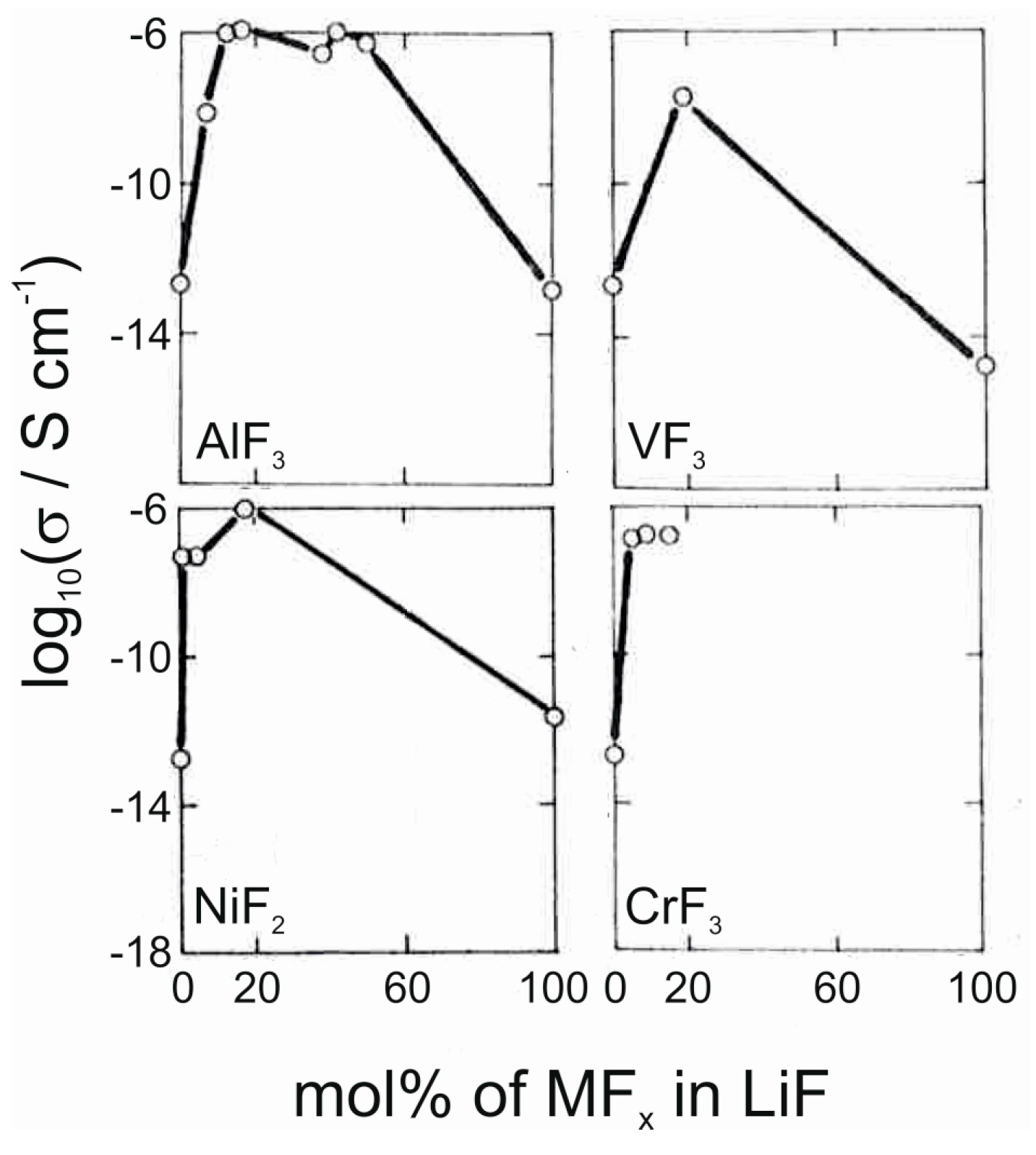
Figure 8.
Schematic illustrating one cycle in ALD. 1. Precursor 1 molecules react with a surface covered with active sites; 2. Reaction side products and excess precursor are purged away; 3. Precursor 2 is introduced and it reacts with the surface covered with precursor 1 molecules; 4. The reaction side products and excess of precursor 2 are again purged away, resulting ideally in one monolayer of material on the substrate.

Figure 9.
The structures of three phosphorus precursors used to deposit lithium phosphate and LiPON. (a) TMPO, or trimethyl phosphate; (b) DEPA, or diethyl phosphoramidate; (c) TDMAP, or tris(dimethylamino)phosphine.
Figure 9.
The structures of three phosphorus precursors used to deposit lithium phosphate and LiPON. (a) TMPO, or trimethyl phosphate; (b) DEPA, or diethyl phosphoramidate; (c) TDMAP, or tris(dimethylamino)phosphine.
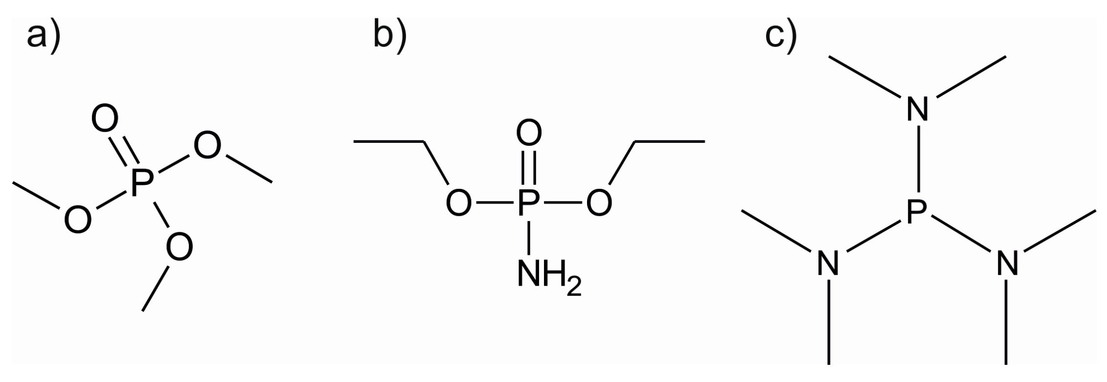
Figure 10.
The amount of lithium cations deposited into lithium tantalate and lithium niobate films as a function of the amount of lithium containing subcycles. Data points obtained from [117,118,119]. The solid line represents the stoichiometry obtained for the lithium tantalate deposited by using 3000 cycles of Lithd and O3 on 50 nm of Ta2O5 in Ref. [104]. The dashed line represents the stoichiometry obtained for the lithium niobate deposited by using same conditions but on Nb2O5 film in Ref. [104]. For stoichiometric LiTaO3 and LiNbO3, the lithium content is 50%.

Figure 11.
The lithium content in lithium aluminosilicate films as a function of the Li2O cycle fraction a/(a + b + c), as determined from syncrotron UPS spectra. Adapted with permission from [121]. Copyright 2014 The Royal Society of Chemistry.
Figure 11.
The lithium content in lithium aluminosilicate films as a function of the Li2O cycle fraction a/(a + b + c), as determined from syncrotron UPS spectra. Adapted with permission from [121]. Copyright 2014 The Royal Society of Chemistry.

Figure 12.
(a) Growth rates of MgF2 films as a function of deposition temperature using different precursor combinations; (b) Growth rates of CaF2 films as a function of deposition temperature using different precursor combinations; (c) Growth rates of AlF3 films as a function of deposition temperature using different precursor combinations; (d) F-Mg ratios of MgF2 films deposited at different temperatures and with different precursor combinations. The HF-process was analysed with XPS and the TiF4 and TaF5 processes with ERDA. Data obtained from References: (a) [147,148,153,154]; (b) [141,155,160]; (c) [143,145,149,156]; (d) [148,153,154].

Figure 13.
(a) Saturation curves for the metal precursor for CaF2, MgF2, YF3 and LiF deposition processes; (b) Saturation curves for the fluorine precursor TiF4 for CaF2, MgF2, YF3 and LiF processes. Data obtained from [150,153,155,157].

Figure 14.
(a) Growth rate of LiF films as a function of Lithd (black squares) and TiF4 (white squares) pulse lengths at 325 °C; (b) Growth rate of LiF films as a function of deposition temperature. Data from [151].
Figure 14.
(a) Growth rate of LiF films as a function of Lithd (black squares) and TiF4 (white squares) pulse lengths at 325 °C; (b) Growth rate of LiF films as a function of deposition temperature. Data from [151].

Figure 15.
(a) Growth rate of AlF3 films as a function of AlCl3 (black) and TiF4 (white) pulse lengths at 160, 200 and 240 °C; (b) Growth rate of AlF3 films as a function of deposition cycles at various deposition temperatures. The AlCl3 pulse time was 0.5 s and the TiF4 pulse time was 1 s. Data from [156].
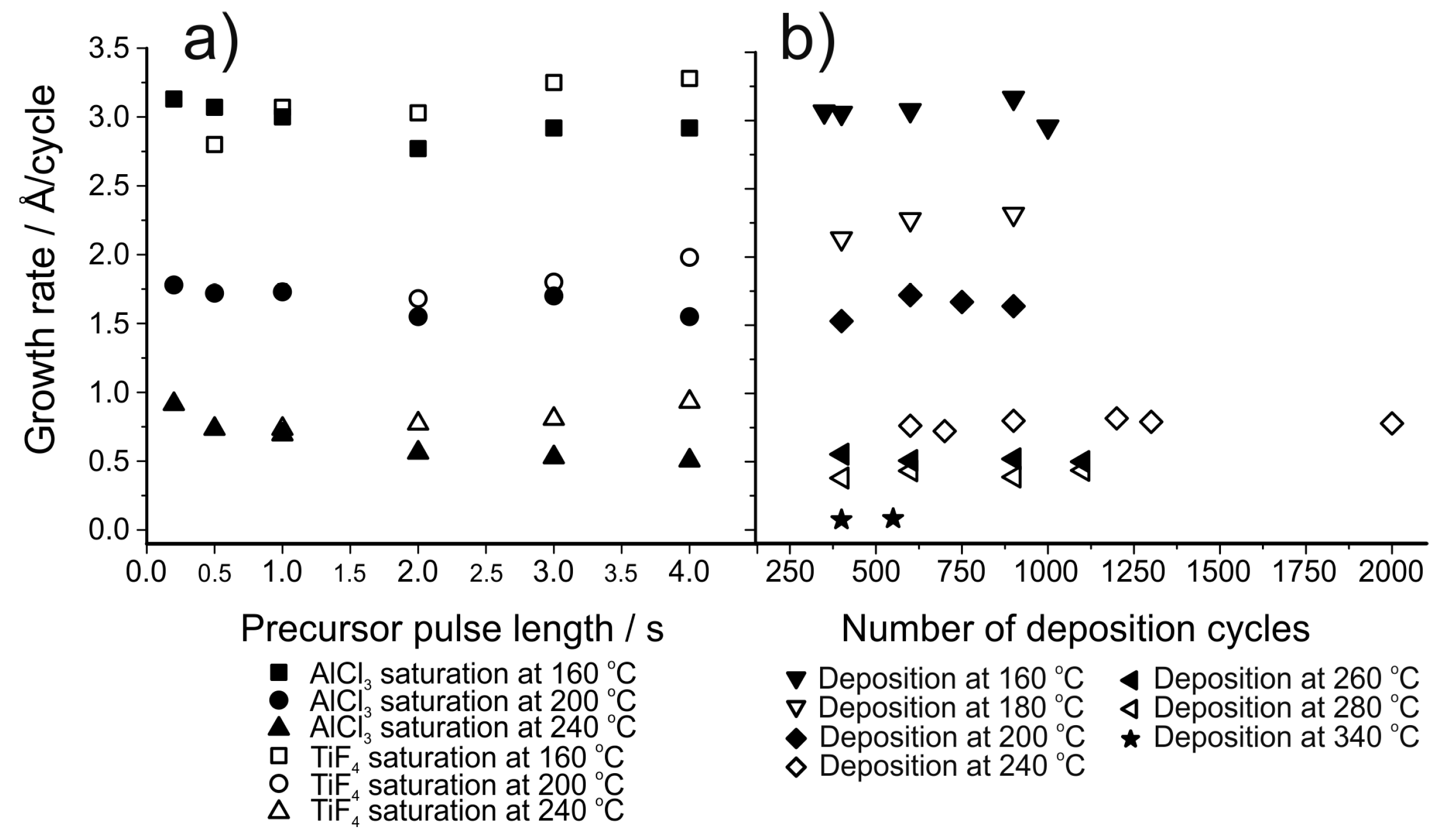
Figure 16.
Gravimetric capacity of coin cells as a function of cycle number with different discharge rates. Black squares denote an NMC-cathode coated with TMA + TaF5. Red circles denote uncoated NMC. Reprinted with permission from [145]. Copyright 2016 American Vacuum Society.
Figure 16.
Gravimetric capacity of coin cells as a function of cycle number with different discharge rates. Black squares denote an NMC-cathode coated with TMA + TaF5. Red circles denote uncoated NMC. Reprinted with permission from [145]. Copyright 2016 American Vacuum Society.

Figure 17.
Process 1 utilizes Al(thd)3 and TiF4 in a conversion reaction to form Li3AlF6 out of LiF thin films. Process 2 uses a conversion reaction between ALD-made AlF3 and the lithium precursor Lithd to deposit Li3AlF6. Reprinted with permission from [139]. Copyright 2017 Elsevier.
Figure 17.
Process 1 utilizes Al(thd)3 and TiF4 in a conversion reaction to form Li3AlF6 out of LiF thin films. Process 2 uses a conversion reaction between ALD-made AlF3 and the lithium precursor Lithd to deposit Li3AlF6. Reprinted with permission from [139]. Copyright 2017 Elsevier.

Figure 18.
AFM images of LiF films deposited at 325 °C using three different processes: (a) Lithd + TiF4, thickness 73 nm, rms roughness 15.9 nm; (b) Mg(thd)2 + TiF4 + Lithd + TiF4, thickness 68 nm, rms roughness 20.1 nm; (c) conversion from a MgF2 film using Lithd, thickness 94 nm, rms roughness 4.8 nm.

Figure 19.
The content of lithium cations in converted AlF3 films as a function of the number of Lithd pulses. Black and white symbols denote samples prepared at different times but with same exposure parameters. Dotted and dashed lines illustrate that the content of lithium increases linearly with the number of Lithd pulses. The solid line illustrates the correct metal stoichiometry of Li3AlF6. Data from [139].

Figure 20.
FESEM images of (a) ~90 nm crystalline Li3AlF6 film made by conversion from AlF3 and Lithd and (b) ~50 nm crystalline Li3AlF6 film made by conversion from AlF3 and Lithd and taken by tilting the sample.
Figure 20.
FESEM images of (a) ~90 nm crystalline Li3AlF6 film made by conversion from AlF3 and Lithd and (b) ~50 nm crystalline Li3AlF6 film made by conversion from AlF3 and Lithd and taken by tilting the sample.


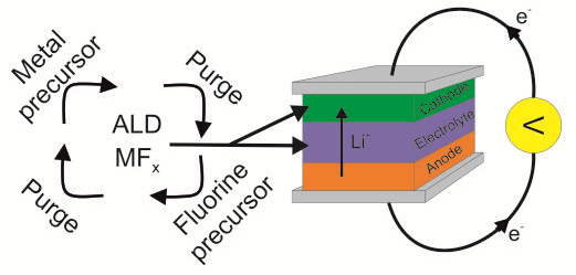
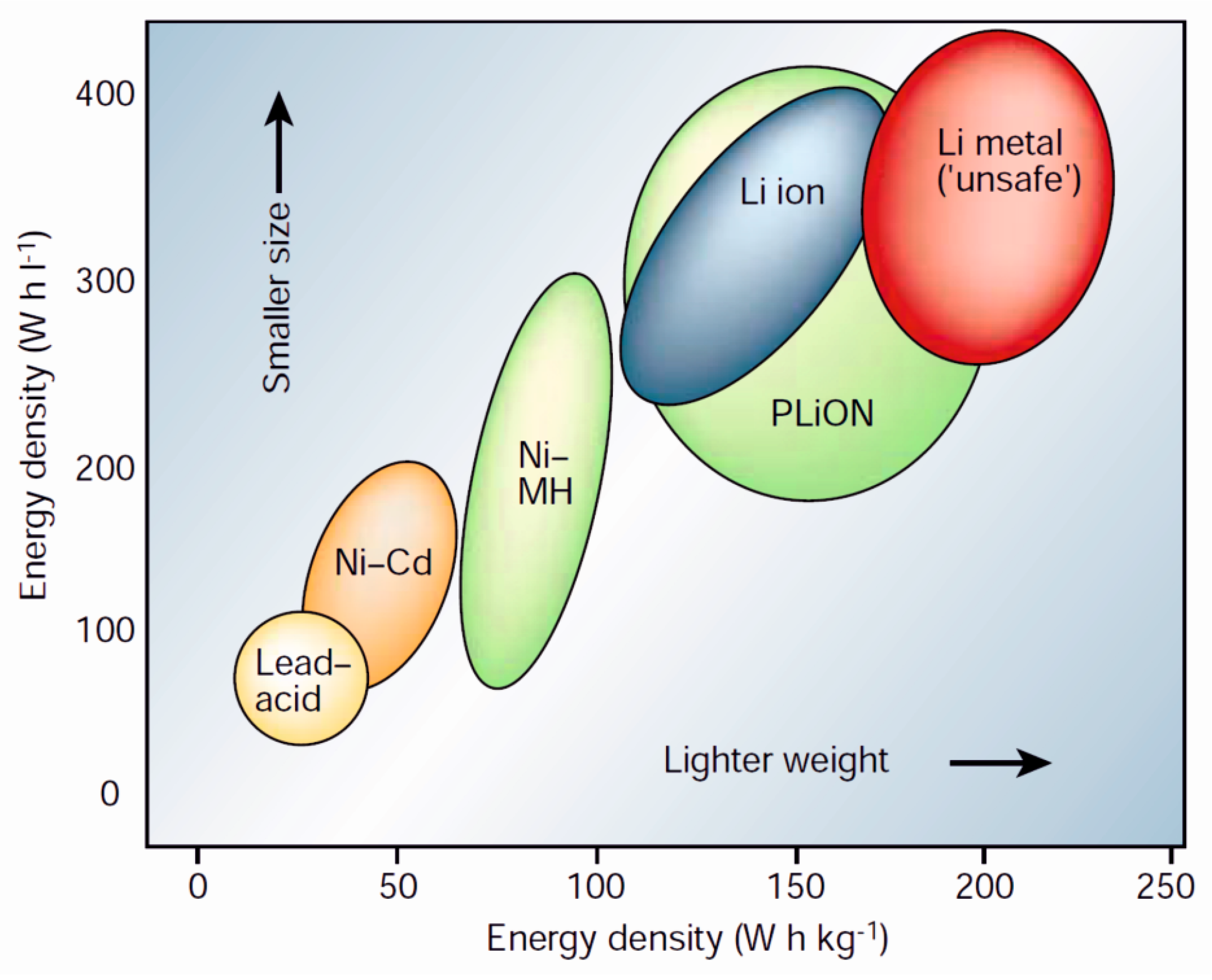
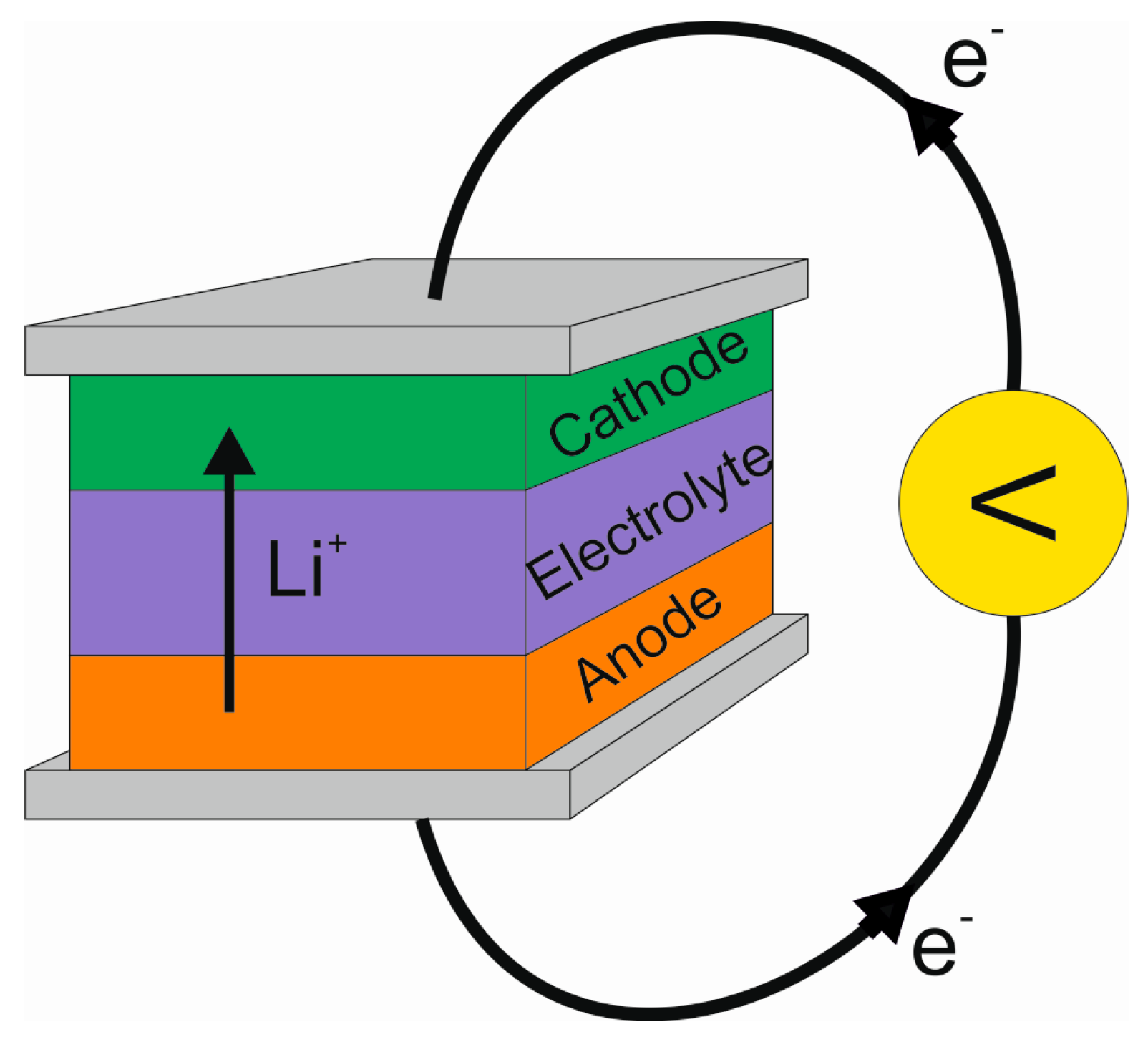
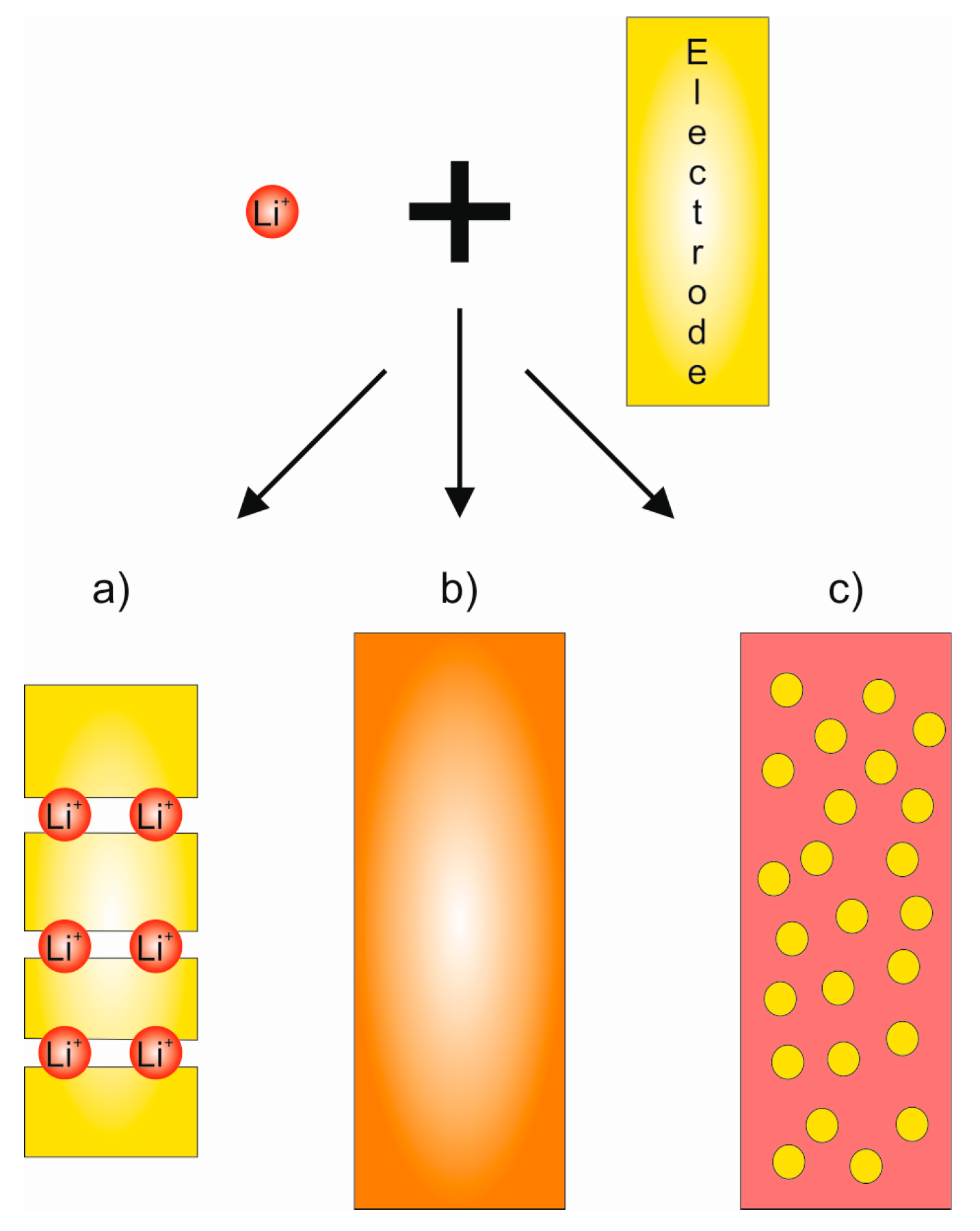
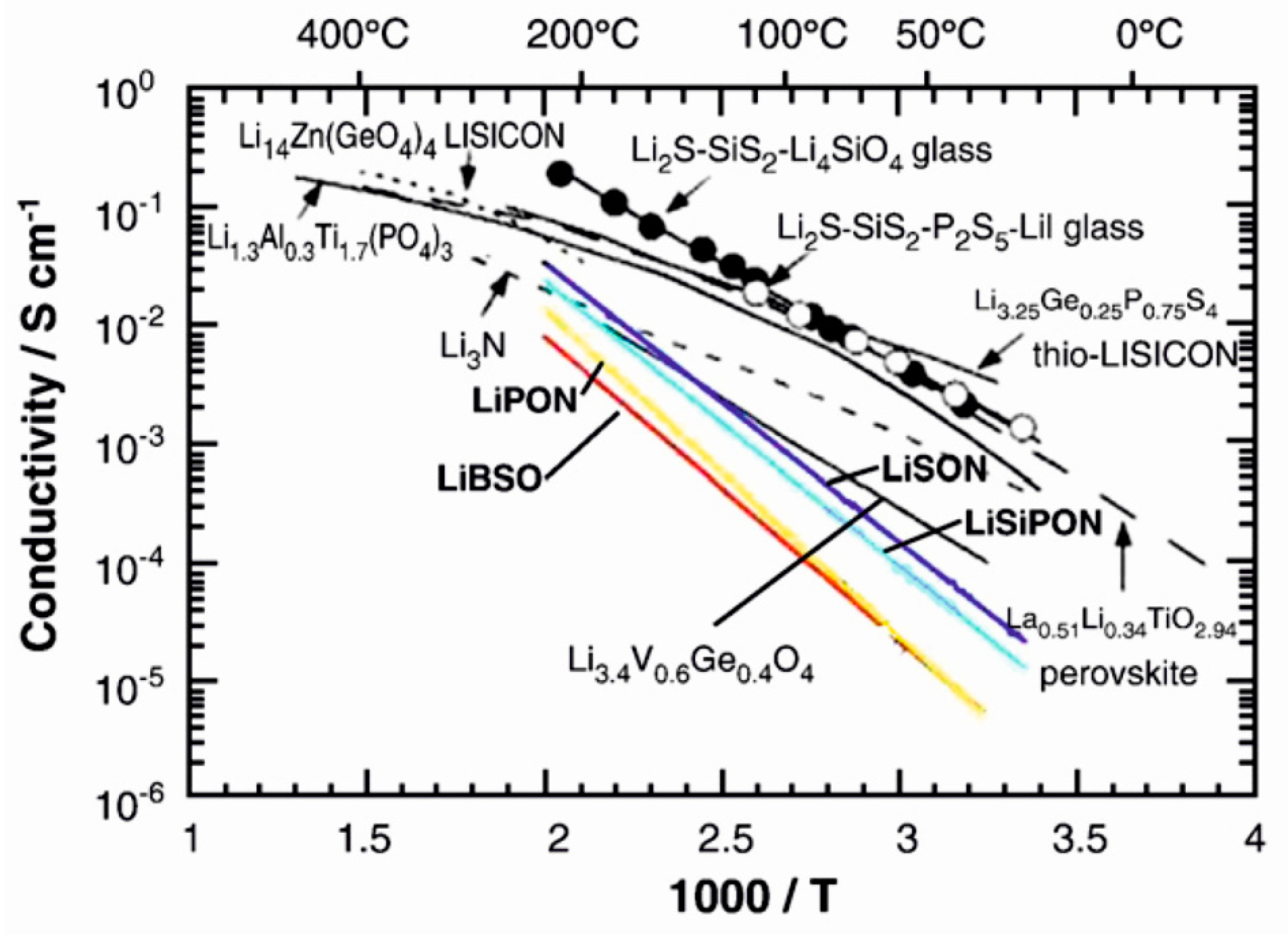
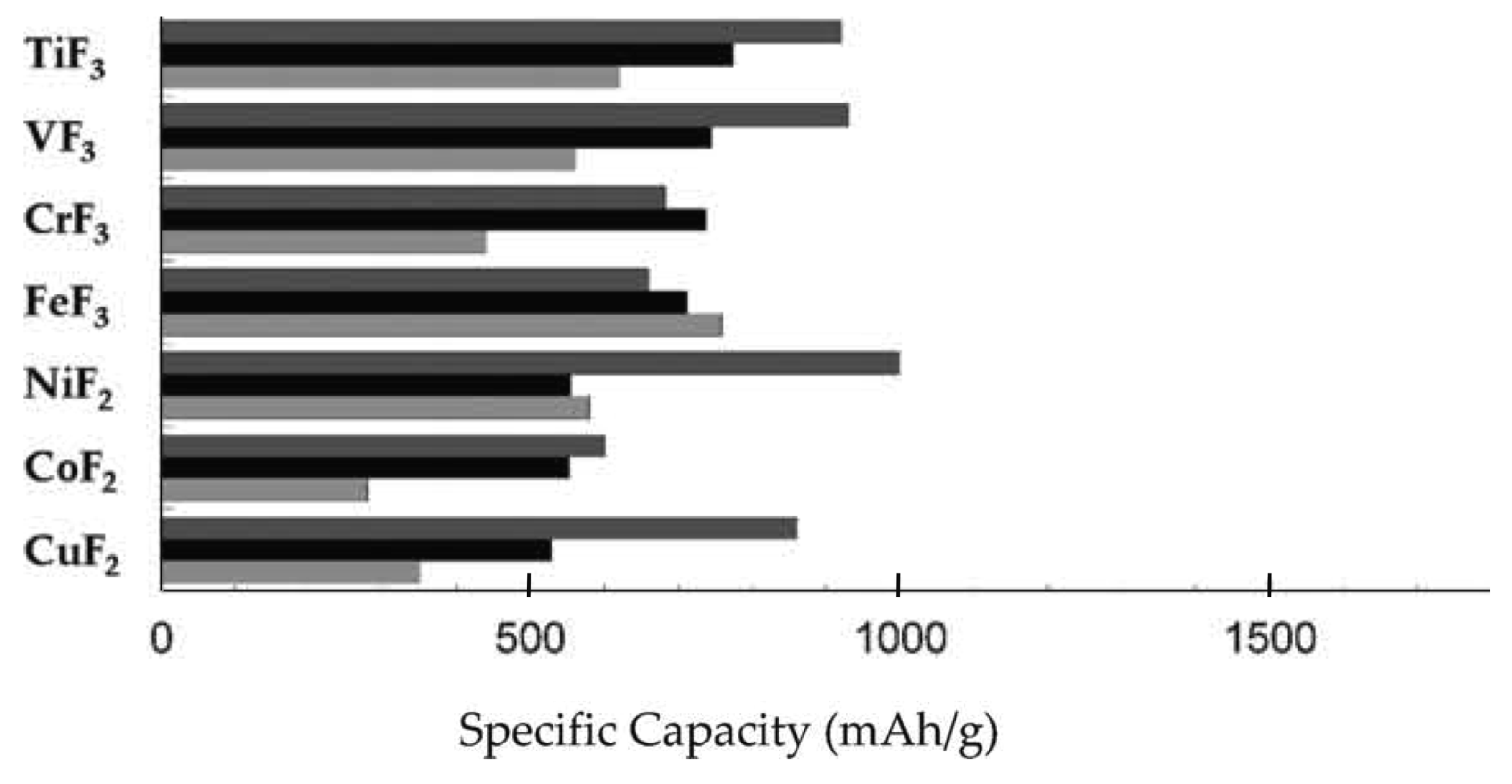
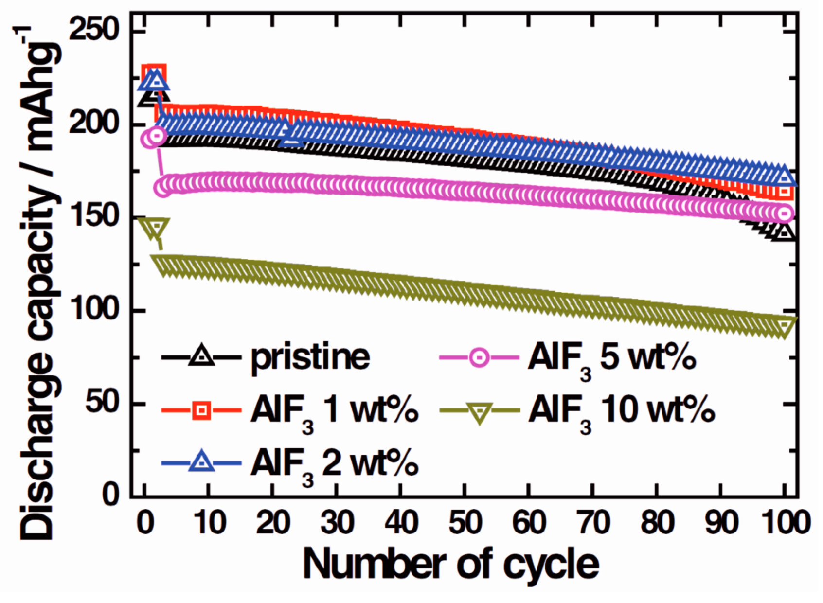
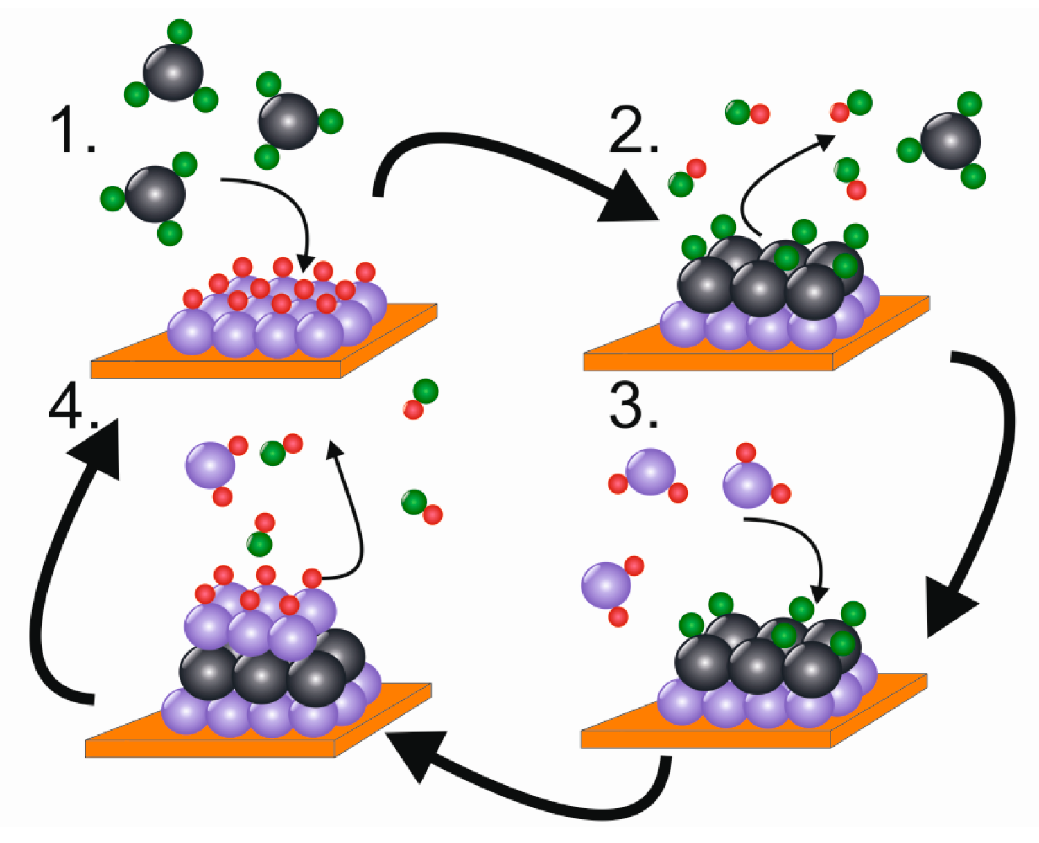
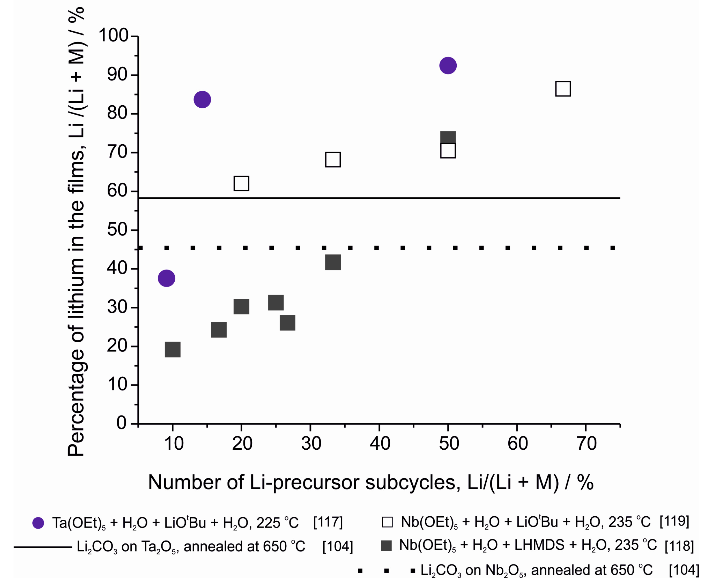
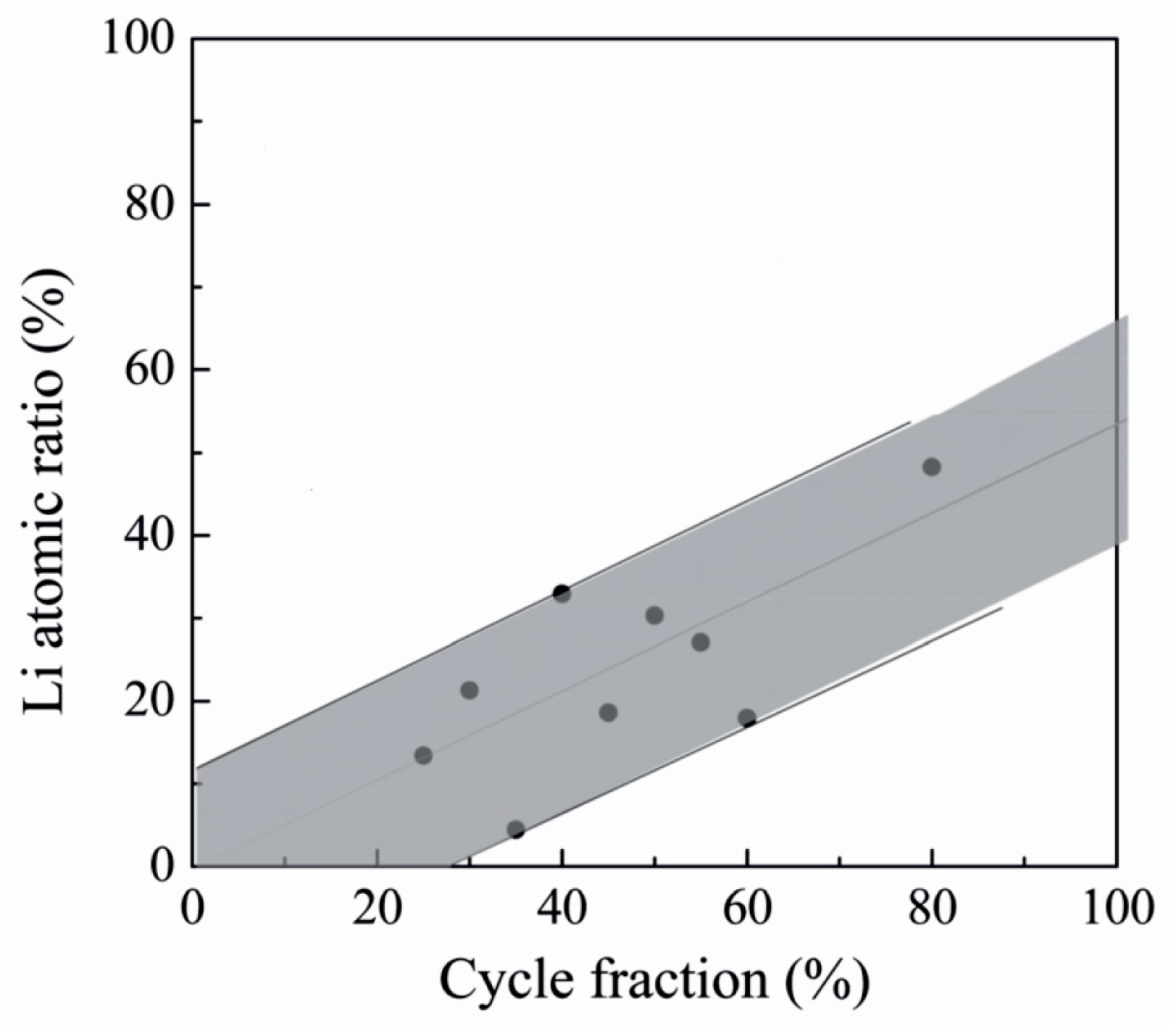
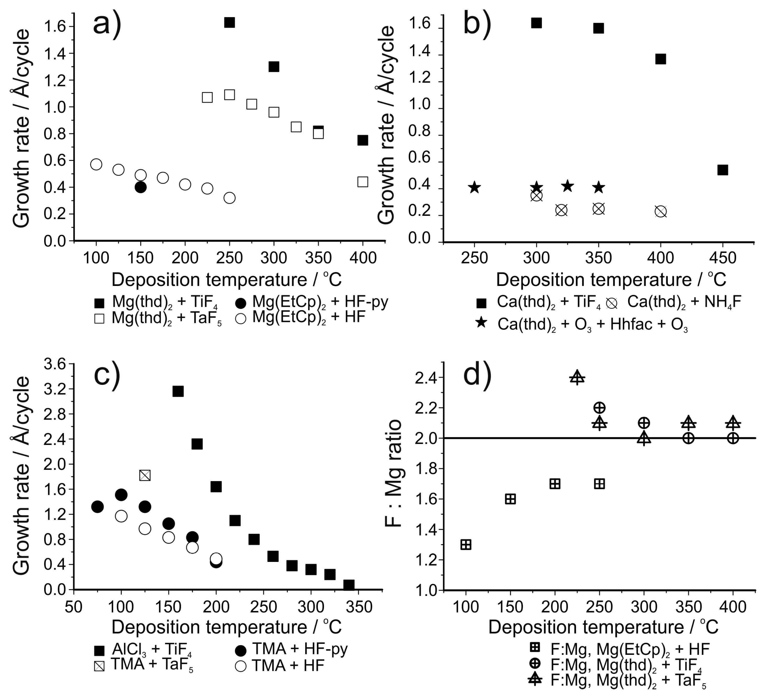
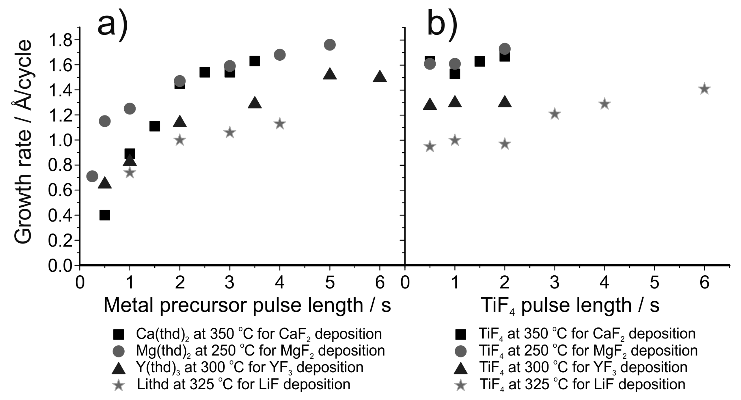
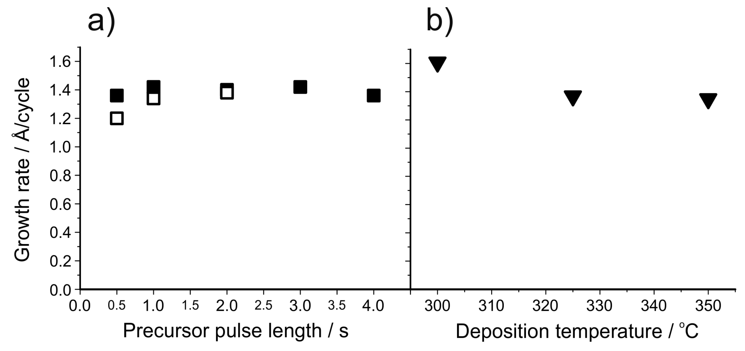
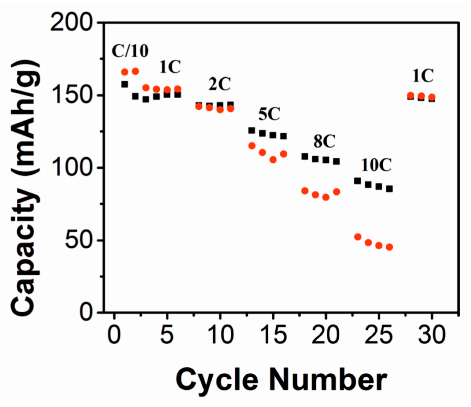
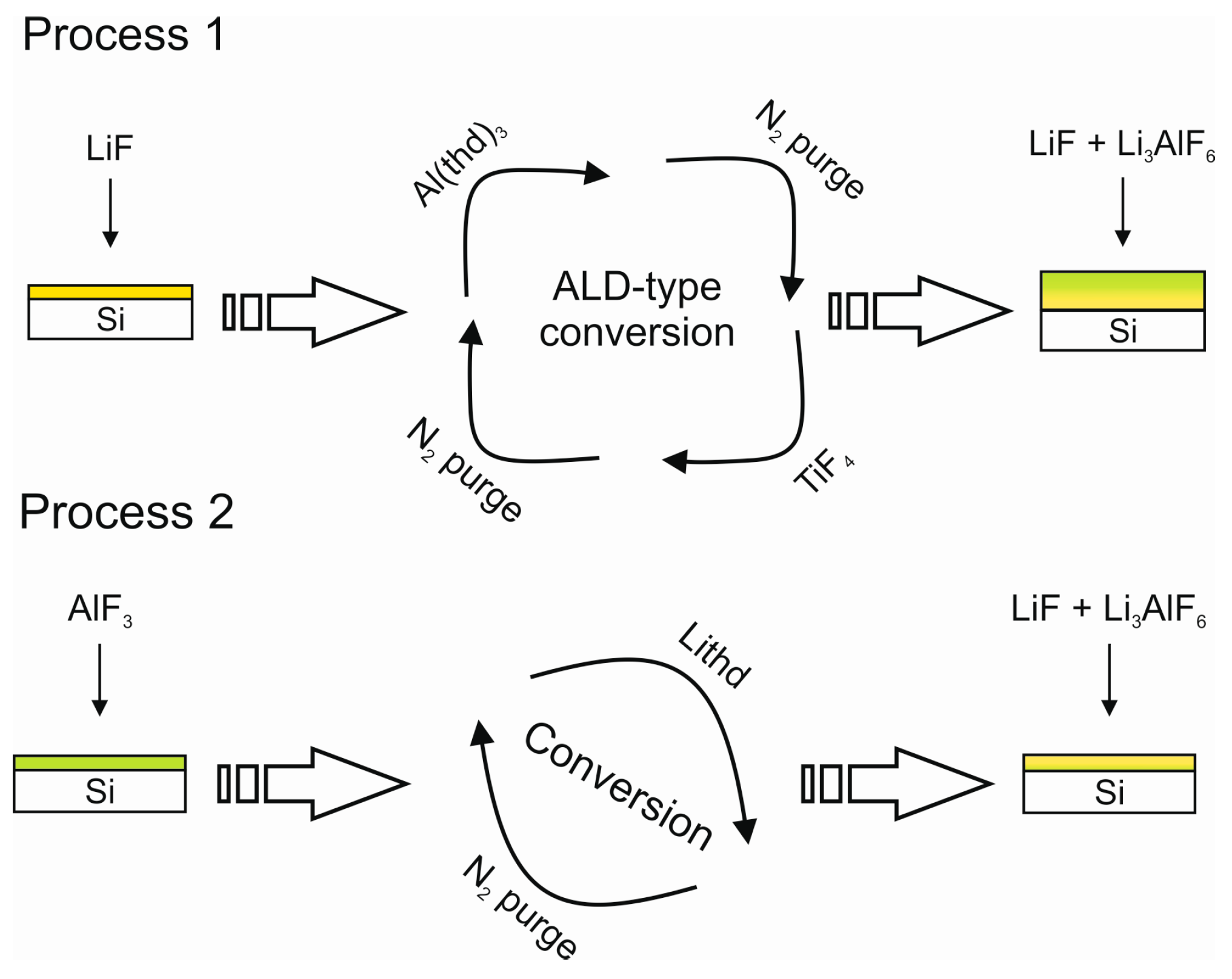
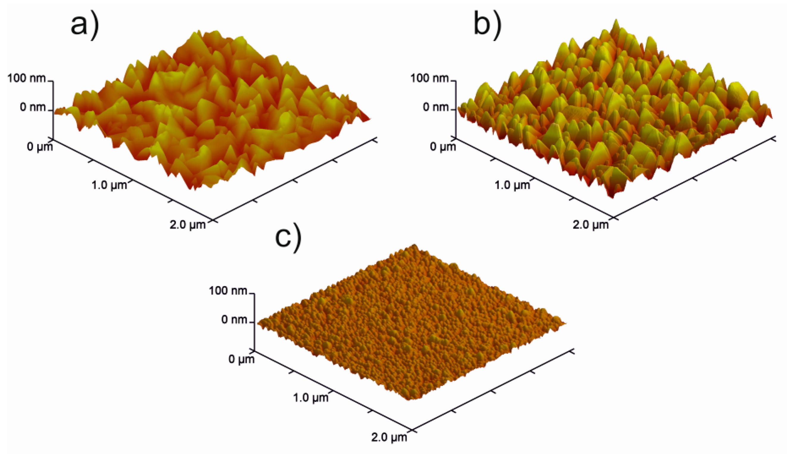
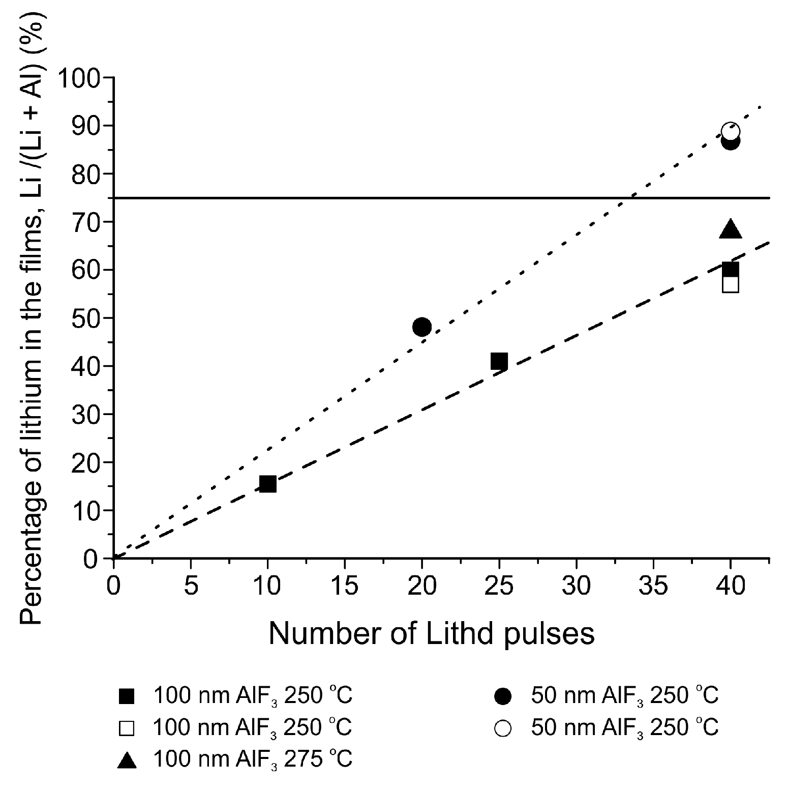
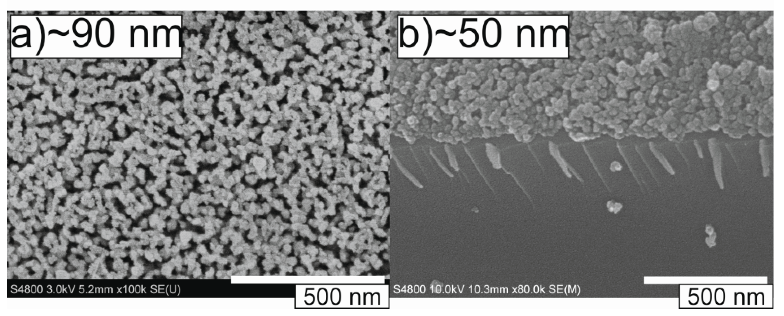
Table 1.
Potentials and capacities obtainable from some of the most studied lithium-ion battery cathode materials.
Table 1.
Potentials and capacities obtainable from some of the most studied lithium-ion battery cathode materials.
| Material | Type | Potential (V) (vs. Li/Li+) | Specific Capacity (mAh/g) | Ref. |
|---|---|---|---|---|
| LiCoO2 | Intercalation | ~3.9 | 140 | [4] |
| LiNiO2 | Intercalation | 2.7–4.1 | 140–200 | [4,19] |
| LiMn2O4 | Intercalation | 3.5–4.5 | 150 | [4] |
| LiFePO4 | Intercalation | 3.4 | 170 | [4,5,19] |
| V2O5 | Intercalation | 3.2–3.4 | 120 | [4] |
Table 2.
Potentials and capacities obtainable from some of the most studied lithium-ion battery anode materials.
Table 2.
Potentials and capacities obtainable from some of the most studied lithium-ion battery anode materials.
| Material | Type | Potential (V) (vs. Li+/Li) | Specific Capacity (mAh/g) | Ref. |
|---|---|---|---|---|
| C6 | Intercalation | <0.6 | 370 | [4,5] |
| Li4Ti5O12 | Intercalation | 1.5 | 175 | [4] |
| Li | Alloying | 0 | 3800 | [26] |
| Si | Alloying | 0.1–0.3 | 3580 | [4,5] |
| Sn | Alloying | 0.6–0.8 | 990 | [4,5,9] |
| MO (M = Co2+, Fe2+, Cu2+, Ni2+) | Conversion | ~1.8–2.0 | 670–750 | [27,28,29] |
Table 3.
Structures and ionic conductivities of some of the most studied solid inorganic lithium-ion conducting materials.
Table 3.
Structures and ionic conductivities of some of the most studied solid inorganic lithium-ion conducting materials.
| Material | Structure | Ionic Conductivity at RT (S/cm) | Ref. |
|---|---|---|---|
| LiPON | Amorphous | 10−8–10−6 | [31,32] |
| Li2O–SiO2–V2O5 (LVSO) | Crystalline/Amorphous | 10−7–10−5 | [32] |
| Li2S–GeS2–Ga2S3 | Amorphous | 10−4 | [32] |
| (Li,La)TiO3 (LLT) | Perovskite | 10−3 | [31,33] |
| LiTi2(PO4)3 | NASICON | 10−5 | [31,32] |
| Li14ZnGe4O16 | LISICON | 10−6 | [33] |
| Li6BaLa2Ta2O12 | Garnet | 10−5 | [31] |
Table 4.
Examples of conventional lithium-ion battery cathode materials deposited by ALD. Abbreviations used: OiPr = iso-propoxide, OtBu = tert-butoxide, Cp = cyclopentadienyl, TMPO = trimethyl phosphate, thd = 2,2,6,6-tetramethyl-3,5-heptanedionato.
Table 4.
Examples of conventional lithium-ion battery cathode materials deposited by ALD. Abbreviations used: OiPr = iso-propoxide, OtBu = tert-butoxide, Cp = cyclopentadienyl, TMPO = trimethyl phosphate, thd = 2,2,6,6-tetramethyl-3,5-heptanedionato.
| Material | Precursors | TDep (°C) | Growth Rate (Å)/Binary Cycle | Capacity (mAh/g) | Ref. |
|---|---|---|---|---|---|
| V2O5 | VO(OiPr)3 + H2O | 105 | 0.15–0.2 | 455 | [85,86] |
| V2O5 | VO(OiPr)3 + O3 | 170–185 | 0.25 | 440 | [86] |
| LixCoyO | LiOtBu + CoCp2 + O2 plasma | 325 | 1.0 with Li:Co pulsing ratio 1:1 | 96 for Li:Co pulsing 1:4 | [87,88] |
| LixFeyPO4 | LiOtBu + FeCp2 + O3 + TMPO + H2O | 300 | 0.85 with Li:Fe pulsing ratio 1:5 | 150 at 0.1 C | [89] |
| LixMnyO | Lithd + Mn(thd)3 + O3 | 225 | 0.2 with Li:Mn pulsing ratio 1:19 | – | [90] |
| LixMnyO | LiOtBu + H2O or Lithd + O3 on MnO2 | 225 | – | 230 | [90] |
| Li2S | LiOtBu + H2S | 150–300 | 1.1 at 150–300 °C | 500 | [91] |
Table 5.
Examples of conventional lithium-ion battery anode materials deposited by ALD. Abbreviations used: OiPr = iso-propoxide, OtBu = tert-butoxide, thd = 2,2,6,6-tetramethyl-3,5-heptanedionato, TPA = terephthalic acid, LiTP = lithium terephthalate.
Table 5.
Examples of conventional lithium-ion battery anode materials deposited by ALD. Abbreviations used: OiPr = iso-propoxide, OtBu = tert-butoxide, thd = 2,2,6,6-tetramethyl-3,5-heptanedionato, TPA = terephthalic acid, LiTP = lithium terephthalate.
| Material | Precursors | TDep (°C) | Growth Rate (Å)/Binary Cycle | Capacity (mAh/g) | Ref. |
|---|---|---|---|---|---|
| TiO2 | Ti(OiPr)4 + H2O | 160 | 0.33 | 330 | [98] |
| LixTiyO | LiOtBu + Ti(OiPr)4 + H2O | 225, 250 | 0.7 with Li:Ti pulsing ratio 1:1 | 40 | [99,100,101] |
| LiTP | Lithd + TPA | 200–280 | 3.0 at 200 °C, decreases with TDep | 350 | [102] |
Table 6.
Examples of potential solid lithium-ion battery electrolyte materials deposited by ALD. Abbreviations used: LiHMDS = lithium hexamethyldisilazide, LiTMSO = lithium trimethyl silanolate, OtBu = tert-butoxide, TEOS = tetraethyl orthosilicate, TMPO = trimethyl phosphate, DEPA = diethyl phosphoramidate, OEt = ethoxide, thd = 2,2,6,6-tetramethyl-3,5-heptanedionato, TMA = trimethyl aluminum, La(FMAD)3 = lanthanum tris(N,N-di-iso-propylformamidinate), TDMAZ = tetrakis(dimethylamido)zirconium , TDMA-Al = tris(dimethylamido) aluminum, HF-py = mixture of HF and pyridine.
| Material | Precursors | TDep (°C) | Growth Rate (Å)/Binary Cycle | Ionic Conductivity (S/cm) | Ref. |
|---|---|---|---|---|---|
| LixSiyO | LiHMDS + O3 | 150–400 | Varies with temperature | Not measured | [110,111] |
| LiTMSO + O3 + H2O | 175–300 | 1.5 at 200–300 °C | Not measured | [112] | |
| LiOtBu + TEOS + H2O | 225–300 | 0.5 at 250 °C | 10−10–10−9 at 30 °C | [113] | |
| Li3PO4 | LiOtBu + TMPO | 225–300 [114] 250–350 [115] | 0.7 at 225–275 °C [114], 0.69 at 300 °C [115] | 10−8–10−7 at RT [115,116] | [114,115,116] |
| LiPON | LiHMDS + DEPA | 250–350 | 0.7 at 270–310 °C | 6.6 × 10⁻⁷ at RT (9.7 at.% nitrogen) | [108] |
| LiOtBu + H2O + TMPO + N2 plasma | 250 | 1.05 | 1.45 × 10⁻⁷ (5.5 at.% nitrogen, increases with nitrogen contents) | [109] | |
| LixTayO | LiOtBu + Ta(OEt)5 + H2O | 225 | 0.7 with Li:Ta pulsing ratio 1:6. | 1.2 × 10⁻⁸ at RT | [117] |
| LixNbyO | LiHMDS + Nb(OEt)5 + H2O | 235 | ~0.64 with Li:Nb pulsing ratio 1:2 | Not measured | [118] |
| LiOtBu + Nb(OEt)5 + H2O | 235 | ~0.68 with Li:Nb pulsing ratio 1:2 | 6.4 × 10⁻⁸ at 30 °C | [119] | |
| LixLayTizO | LiOtBu + La(thd)3 + TiCl4 + O3 + H2O | 225 | Varies with pulsing ratio | Not measured. | [120] |
| LixAlySizO | LiOtBu + TMA + TEOS + H2O | 290 | 1.0 with Li:Al pulsing ratio 6:10 | 10−9–10−7 at RT, depends on Li contents | [121] |
| LixLayZrzO:Al | LiOtBu + La(FMAD)3 + TDMAZ + TMA + O3 | 225 | 1.0 with Li:La:Zr:Al ratio 8:28:12:1 | 1 × 10⁻⁸ at RT for amorphous film | [122] |
| LixAlyS | LiOtBu + TDMA-Al + H2S | 150 | 0.5 with Li:Al ratio 1:1 | 2.5 × 10⁻⁷ at RT | [123] |
| LixAlyF | LiHMDS + TMA + HF-py | 150 | 0.45 with Li:Al pulsing ratio 1:1 | 7.5 × 10⁻⁶ at RT | [51] |
| LiOtBu + AlCl3 + TiF4 | 250 | 1 with Li:Al pulsing ratio 1:1 | (3.5 ± 0.5) × 10−8 at RT | [124] |
Table 7.
ALD processes reported for fluoride materials. Abbreviations used: LiHMDS = lithium hexamethyldisilazide, HF-py = mixture of HF and pyridine, EtCp = ethylcyclopentadienyl, thd = 2,2,6,6-tetramethyl-3,5-heptanedionato, TMA = trimethyl aluminum, Ac = acetate, DEZ = diethylzinc, TEMAZ = tetrakis(ethylmethylamido) zirconium, OtBu = tert-butoxide, TDMAH = tetrakis(dimethylamido) hafnium, hfac = 1,1,1,5,5,5-hexafluoro-2,4-pentanedionato.
| Material | Precursors | TDep (°C) | Growth Rate (Å)/Cycle | Ref. |
|---|---|---|---|---|
| Fluorides Using HF as the Fluorine Precursor | ||||
| LiF | LiHMDS + HF-py | 150 | 0.5 | [147] |
| MgF2 | Mg(EtCp)2 + HF-py | 150 | 0.4 | [147] |
| MgF2 | Mg(EtCp)2 + HF | 100–250 | Varies, 0.6 at 100 °C | [148] |
| CaF2 | Ca(thd)2 + HF/NH4F | 300–400 | 0.2 at 320–400 °C | [141] |
| SrF2 | Sr(thd)2 + HF/NH4F | 260–320 | Varies, 0.6 at 300 °C | [141] |
| AlF3 | TMA + HF-py | 75–300 | Varies, 1.0 at 150 °C | [143] |
| AlF3 | TMA + HF | 100–200 | Varies, 1.2 at 100 °C | [149] |
| MnF2 | Mn(EtCp)2 + HF-py | 150 | 0.4 | [147] |
| ZnF2 | Zn(Ac)2·2H2O + HF/NH4F | 260–320 | 0.7 at 260–300 °C | [141] |
| ZnF2 | DEZ + HF-py | 150 | 0.7 | [147] |
| ZrF4 | TEMAZ + HF-py | 150 | 0.9 | [147] |
| ZrF4 | Zr(OtBu)4 + HF-py | 150 | 0.6 | [147] |
| HfF4 | TDMAH + HF-py | 150 | 0.8 | [147] |
| LixAlyF | LiHMDS + TMA + HF-py | 150 | 0.45 with Li:Al pulsing ratio 1:1 | [51,146] |
| Fluorides Using Metal Fluorides as the Fluorine Precursor | ||||
| LiF | Lithd + TiF4 | 250–350 | 1.0 at 325 °C | [150] |
| LiF | Mg(thd)2 + Lithd + TiF4 | 300–350 | 1.4 at 325 °C | [151] |
| LiF | LiOtBu + WF6 | 150–300 | – | [152] |
| LiF | LiOtBu + MoF6 | 150–300 | 2.6 | [152] |
| LiF | LiOtBu + TiF4 | 200–300 | 0.5 at 250 °C | [124] |
| MgF2 | Mg(thd)2 + TiF4 | 250–400 | Varies, 1.6 at 250 °C | [153] |
| MgF2 | Mg(thd)2 + TaF5 | 225–400 | Varies, 1.1 at 225–250 °C | [154] |
| CaF2 | Ca(thd)2 + TiF4 | 300–450 | Varies, 1.6 at 300–350 °C | [155] |
| AlF3 | AlCl3 + TiF4 | 160–340 | Varies, 0.75 at 240 °C | [156] |
| AlF3 | TMA + TaF5 | 125–350 | Varies, 1.9 at 125 °C | [145] |
| YF3 | Y(thd)3 + TiF4 | 175–325 | Varies, 1.3–1.5 at 200–300 °C | [157] |
| LaF3 | La(thd)3 + TiF4 | 225–350 | Varies, 5.2 at 225–250 °C | [158] |
| LixAlyF | LiF + Al(thd)3 + TiF4 | 250–350 | – | [139] |
| LixAlyF | LiOtBu + AlCl3 + TiF4 | 250 | 1 | [124] |
| AlWxFy | TMA + WF6 | 200 | 1–1.5 | [144,159] |
| Fluorides Using Other Processes | ||||
| LiF | MgF2 + Lithd | 275–325 | – | [151] |
| MgF2 | Mg(thd)2 + Hhfac + O3 | – | 0.38 | [160] |
| CaF2 | Ca(hfac)2 + O3 | 300 | 0.3 | [160] |
| CaF2 | Ca(thd)2 + Hhfac + O3 | 250–350 | 0.4 | [160] |
| AlF3 | TMA + SF6 plasma | 50–300 | Varies, 0.85 at 200 °C | [161] |
| LaF3 | La(thd)3 + Hhfac + O3 | – | 0.49 | [160] |
| LixAlyF | AlF3 + Lithd | 250–300 | – | [139] |
© 2018 by the authors. Licensee MDPI, Basel, Switzerland. This article is an open access article distributed under the terms and conditions of the Creative Commons Attribution (CC BY) license (http://creativecommons.org/licenses/by/4.0/).
Share and Cite
MDPI and ACS Style
Mäntymäki, M.; Ritala, M.; Leskelä, M. Metal Fluorides as Lithium-Ion Battery Materials: An Atomic Layer Deposition Perspective. Coatings 2018, 8, 277. https://doi.org/10.3390/coatings8080277
AMA Style
Mäntymäki M, Ritala M, Leskelä M. Metal Fluorides as Lithium-Ion Battery Materials: An Atomic Layer Deposition Perspective. Coatings. 2018; 8(8):277. https://doi.org/10.3390/coatings8080277
Chicago/Turabian StyleMäntymäki, Miia, Mikko Ritala, and Markku Leskelä. 2018. "Metal Fluorides as Lithium-Ion Battery Materials: An Atomic Layer Deposition Perspective" Coatings 8, no. 8: 277. https://doi.org/10.3390/coatings8080277
Note that from the first issue of 2016, this journal uses article numbers instead of page numbers. See further details here.