Visually Attractive and High-Power-Retention Solar Modules by Coloring with Automotive Paints


1
X-Frontier Division, Toyota Motor Corporation, 1200 Mishuku, Susono, Shizuoka 410-1193, Japan
2
Material Research Department, Toyota Research Institute of North America, 1555 Woodridge Avenue, Ann Arbor, MI 48105, USA
*
Author to whom correspondence should be addressed.
Coatings 2018, 8(8), 282; https://doi.org/10.3390/coatings8080282
Submission received: 13 June 2018
/
Revised: 30 July 2018
/
Accepted: 11 August 2018
/
Published: 15 August 2018
(This article belongs to the Special Issue Thin Film Solar Cells: Fabrication, Characterization and Applications)
Abstract
:The automotive painting technique is highly advantageous for coloring solar modules, because it enables the modules to be visually attractive over a large area, numerous colors can be applied, and they are highly durable. Herein, we present a high-performance solar module colored using an automotive painting technique. We coated a dilute automotive pigment, the high-transmittance mica pigment, with a clear coat material on a crystalline Si solar module to generate blue color. Our measurements show that a pigment weight concentration of around 10% with the mica pigment is suitable for painting the solar modules, because it enables visual attractiveness while retaining over 80% of the output power, compared to the original solar module. We believe that the technique proposed herein can considerably increase the installable area of solar modules on a car body.
1. Introduction
In 2012, the U.S. Environmental Protection Agency and National Highway Traffic Safety Administration laid down strict standards for CO2 emissions and improved fuel economy for light-duty vehicles covering the model years (MYs) 2017 to 2025 [1]. The new emission rules require an average fuel economy of 23.2 km/L (equivalent to CO2 emissions of 100 g/km) for light-duty vehicles by MY 2025. Similar rules have been established by the EU, Japan, and other countries and regions. Accordingly, automakers have been developing various types of environmentally friendly vehicles (EFVs), such as electric vehicles (EVs), hybrid vehicles (HVs), plug-in hybrid vehicles (PHVs), and fuel cell vehicles (FCVs) to help reduce CO2 emissions. Although nearly one quarter of the MY 2017 vehicles already meet or exceed MY 2020 targets, with the addition of expected air conditioning improvements and off-cycle credits, only 5% of MY 2017 production, comprising solely EVs, HVs, PHVs, and FCVs, can meet the MY 2025 CO2 emission targets [2]. Therefore, it is important to develop other technologies that use renewable energy as the driving power, to achieve further reductions in CO2 emissions.
Power generation by solar cells/modules is a promising renewable energy candidate for future cars, because most EFVs are equipped with large-capacity batteries that can be charged with electricity generated by solar cells/modules. It has been reported that installing 800 W rated power solar modules on automobiles can greatly reduce CO2 emissions from passenger cars in Japan by 63% [3]. However, these modules need to be installed not only on the roof, but also on the side doors, engine hood, and the hatch of passenger cars, because standard passenger cars such as the Toyota Prius have very limited surface area on the roof [3]. Furthermore, standard solar modules are monochromatic and usually either blue or black in color, because the modules need to be good light absorbers to enable high-efficiency conversion; this affects the overall appearance of the automobile [4,5]. Therefore, there is urgent need to develop decorative modules that can be painted with the desired colors. Various ways to prepare colorful solar cells/modules have been studied for over a decade, which involve the use of dyes [6], colloidal quantum dots [7], photonic filters [8,9], integrated liquid/photonic crystals [10,11], dielectric mirrors, and optical microcavities [12,13], and modified top/bottom electrodes [14,15]; however, none have been applied for the mass production of solar cells/modules owing to the lack of color variation, durability, and other drawbacks such as difficulty in scale-up to the size of practical solar modules.
This work presents a novel way to obtain colored solar modules, via the automotive paint technique. Automotive paints are suitable for coloring solar modules, because they can make the automobile visually attractive, can be applied over a large area, are durable, and can be coated on three-dimensional surfaces as well [16]. In addition, roughly 40,000 automobile colors are known today, and approximately 1000 new colors are added to this list each year [17]. The challenge in paint application on solar modules is to make them visually attractive while maintaining the level of output power. However, application of a color would imply the reflection of a certain range of wavelengths; hence, it is inevitable that the output power of the solar modules would be reduced. To simultaneously maintain a high output power and visual attractiveness, we propose the use of dilute interference pigments, such as mica pigments, that have large transmittance because they acquire color through the interference effect with a transparent layer on a transparent flake. To the best of our knowledge, this is the first study that uses interference automotive pigments to color solar modules. The subsequent sections detail the preparation and analysis of a high-performance colored solar module using automotive mica pigments.
2. Materials and Methods
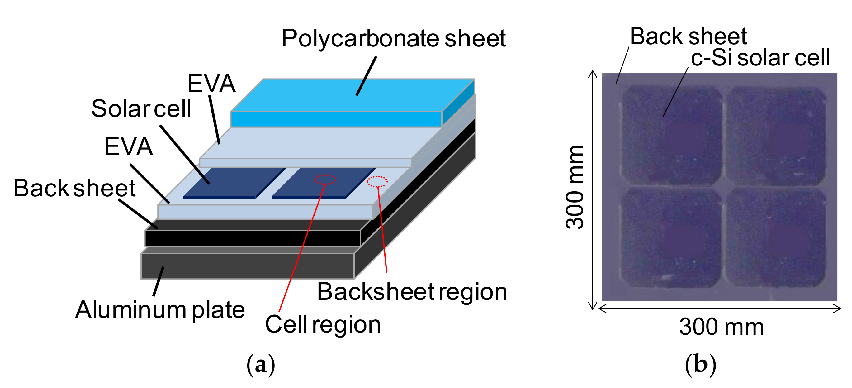
The solar module used in this study was originally developed for automotive applications, and is based on a monocrystalline Si (c-Si) solar cell [18]. Replacement of a steel-top car roof with conventional solar modules leads to an increase in the total weight of the car and change in the center of mass, because the weight per area of the module is greater than that of the steel roof; this is not suitable for car designs. Therefore, weight reduction is essential to equip passenger cars with solar modules. Figure 1a shows the schematic of the solar module. For the top cover, a polycarbonate sheet was used, owing to its lower weight compared to the conventionally used glass plate. The solar cells, which were 0.2 mm-thick back-contact type c-Si cells (125 × 125 mm2), were encapsulated in a standard encapsulant of ethylene-vinyl-acetate (EVA). For the bottom substrate, aluminum plate was selected, which is light and rigid, and is used for some lightweight car bodies. The photo of the fabricated solar module with four solar cells is shown in Figure 1b. To limit the impact on vehicle mass, the area density of the solar modules was approximately 5.5 kg/m2, which is almost the same as that of the conventional steel roof used in passenger cars.
Color was generated on the solar module by coating it with a dilute pigment (i.e., a mixture of a pigment and an automotive clearcoat material). We first coated a 20 μm-thick layer of dilute pigment, followed by a 50 μm-thick clearcoat layer (polyurethane; thickness measured after curing). The clearcoat material provides durability, environmental etch, and scratch resistance to the coatings. The pigments used for the paints were the standard mica pigment (BASF 9680H, BASF, Ludwigshafen am Rhein, Germany) as the semi-transparent pigment, and omnidirectional structural color (OSC) pigments [19] as the non-transparent pigment for comparison. Both pigments impart blue color when applied to cars. Since the mica pigment, which was obtained by coating metal oxides on a flat surface of mica flakes, generates color through light interference, it has high transparency. On the other hand, the OSC pigment is highly reflective because it is produced by coating multiple semiconductor layers on an aluminum flake; hence, the pigment has no transparency. The dilute pigment layer not only generates colors, but also acts as a primer. All layers were coated by the blade-coating method. We varied the pigment weight concentration (PWC) from 0% to 10% to investigate the relationship between PWC and the appearance or output power of the solar module.
The properties of the color on the solar module were measured above the cell (cell region) as well as above the backsheet (backsheet region), as shown in Figure 1a, with a spectrophotometer (Konica Minolta CM512M3A, Tokyo, Japan). We focused on the color difference between the cell region and backsheet region, because the entire module should have a uniform color to enable automotive application. The spectrophotometer provides L*a*b* values in the CIE1976 L*a*b* color space for each region, and the color difference ΔE is defined as ((ΔL*)2 + (Δa*)2 + (Δb*)2)1/2, where ΔL*, Δa*, Δb* are the differences of L*, a*, and b* values between the cell and backsheet regions [20]. The transmittance (T) and reflection (R) of the dilute pigment layers were measured with a V-570 spectrometer (JASCO Corporation, Tokyo, Japan), while the microstructure of the layers was observed with an optical microscope (Nikon Optiphot 150, Nikon, Tokyo, Japan). The solar module characteristics were evaluated from the illuminated current–voltage (LIV) measurements under approximate air mass 1.5 G illumination (100 mW/cm2) at room temperature using the YSS-150E measurement system (Eikoseiki, Tokyo, Japan; steady state tester with class AAA).
3. Results and Discussions
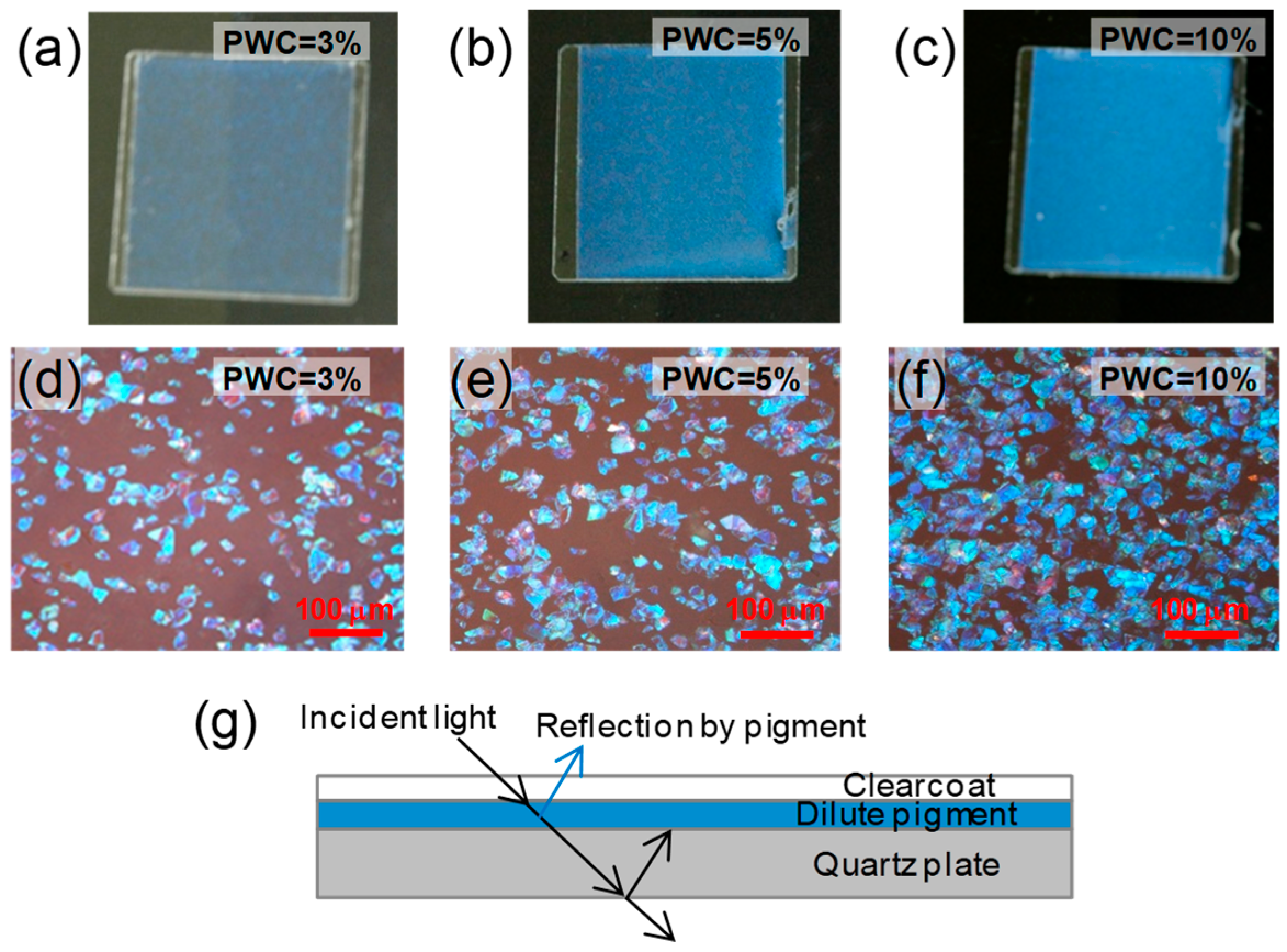
Figure 2a–c shows images of the coated dilute mica pigment on the quartz plate (20 × 20 mm2), which was placed on a black backsheet in order to reduce light incidence from the back side. Figure 2d–f show microscope images of the dilute pigment with varying PWCs. Clearly, although the pigments do not spread all over the area without gaps between them, the dilute pigment provides a uniform color throughout the fabricated area (20 × 20 mm2) even when the PWC is 3%. This is because the orientation of the pigment is random.
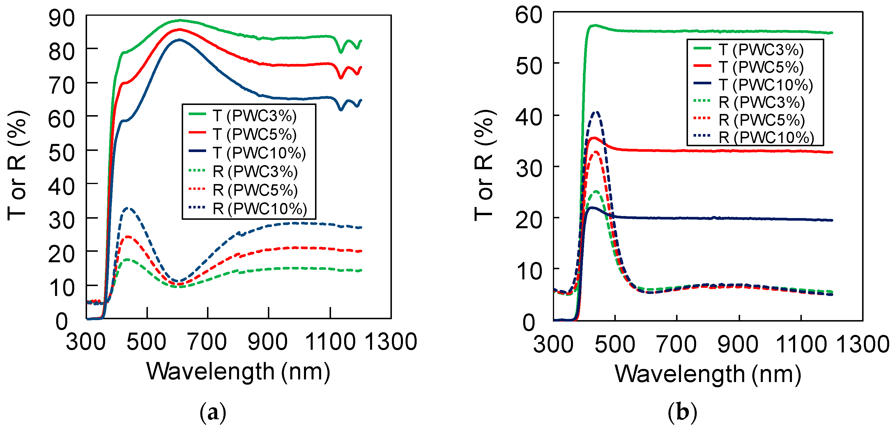
We then investigated the transmittance and reflection of the diluted pigment layers for both the mica and OSC pigments as a function of PWC. A dilute pigment-coated quartz plate (1 mm thick) was used for the measurements. Notably, the experimental data also consider the reflection at the back side of the quartz plate as shown in Figure 3g, which is nearly nil when the paint is applied to the solar module. Figure 3 shows the measurement results for (a) the mica pigment and (b) the OSC pigment. The R value is relatively large in the wavelength region of 400–500 nm for both pigments. Because almost all the photons transmitted through the dilute pigment layers in the visible region are absorbed by the solar cell or black backsheet, which is located under the layers, a blue color is generated, as shown in Figure 2. Owing to their similar reflection spectra in the wavelength region of 400–500 nm, both dilute pigments exhibit a similar blue color when coated on the solar module.
The R in the wavelength region of 400–500 nm become large as the PWC increases for both pigments. For the mica pigment, the peak T at around 600 nm is maintained at around 85%, and drops in small steps in the wavelength region of 800–1100 nm with increasing PWC. On the other hand, the T of the dilute OSC pigment reduces in larger steps over the entire region with increasing PWC. This is because the OSC pigment is designed to absorb photons in the visible and near-IR regions, except at 400–500 nm, in order to impart a bright appearance. The maximum T for the mica pigment is ~88%, while that for the OSC pigment is ~58% (Figure 3; note that the two graphs in Figure 3 have different scales for the vertical axes). The results indicate that the dilute mica pigment is suitable for coloring the solar module, because it provides a large T throughout the active region of the Si solar cell, except in a very narrow visible region for generating color.
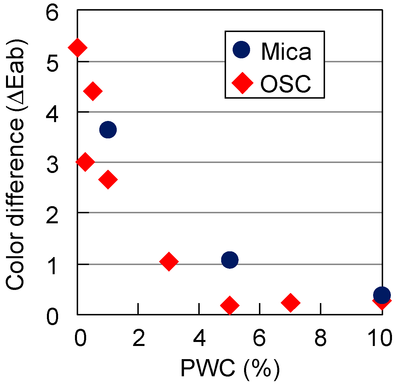
We then measured the color difference (ΔE) between the cell region and backsheet region of the colored solar modules using both dilute pigments, as a function of PWC. Figure 4 shows that ΔE reduces as PWC increases for both pigments. Although the mica pigment has much larger transmittance in the visible region compared to the OSC pigment, both dilute pigments exhibit a similar trend for ΔE reduction as a function of PWC. When the PWC exceeds 5% for the mica pigment, the paints provide a ΔE of less than 1, which is not perceptible to the naked eye, thus exhibiting the potential of the paint for application to solar modules due to the uniform generation of color throughout the module [21].
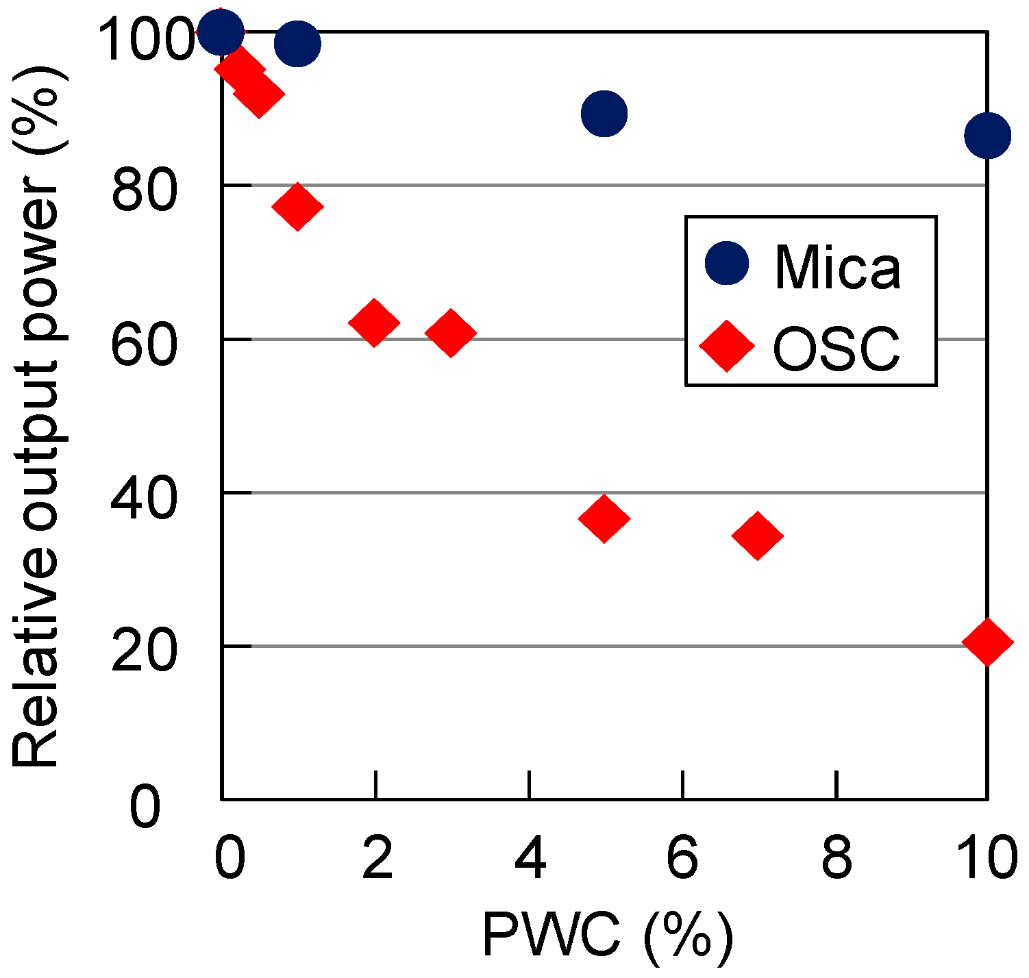
Having identified that the dilute mica pigment imparts a good appearance to the c-Si solar module with high transmittance, we then investigated the output power from the colored solar module. Figure 5 shows the measured relative output power as a function of PWC. The relative output power was defined as the power with the color paint/the power without the color paint. Although the OSC exhibited a brighter appearance, there was a significant reduction in output power with increasing PWC. On the other hand, the mica pigment showed a smaller output power reduction, and retained 80% of the original output power at a PWC of 10%.
Thus, we concluded that the mica pigment with 10% PWC is suitable for painting solar modules, both appearance-wise and in terms of power conservation.
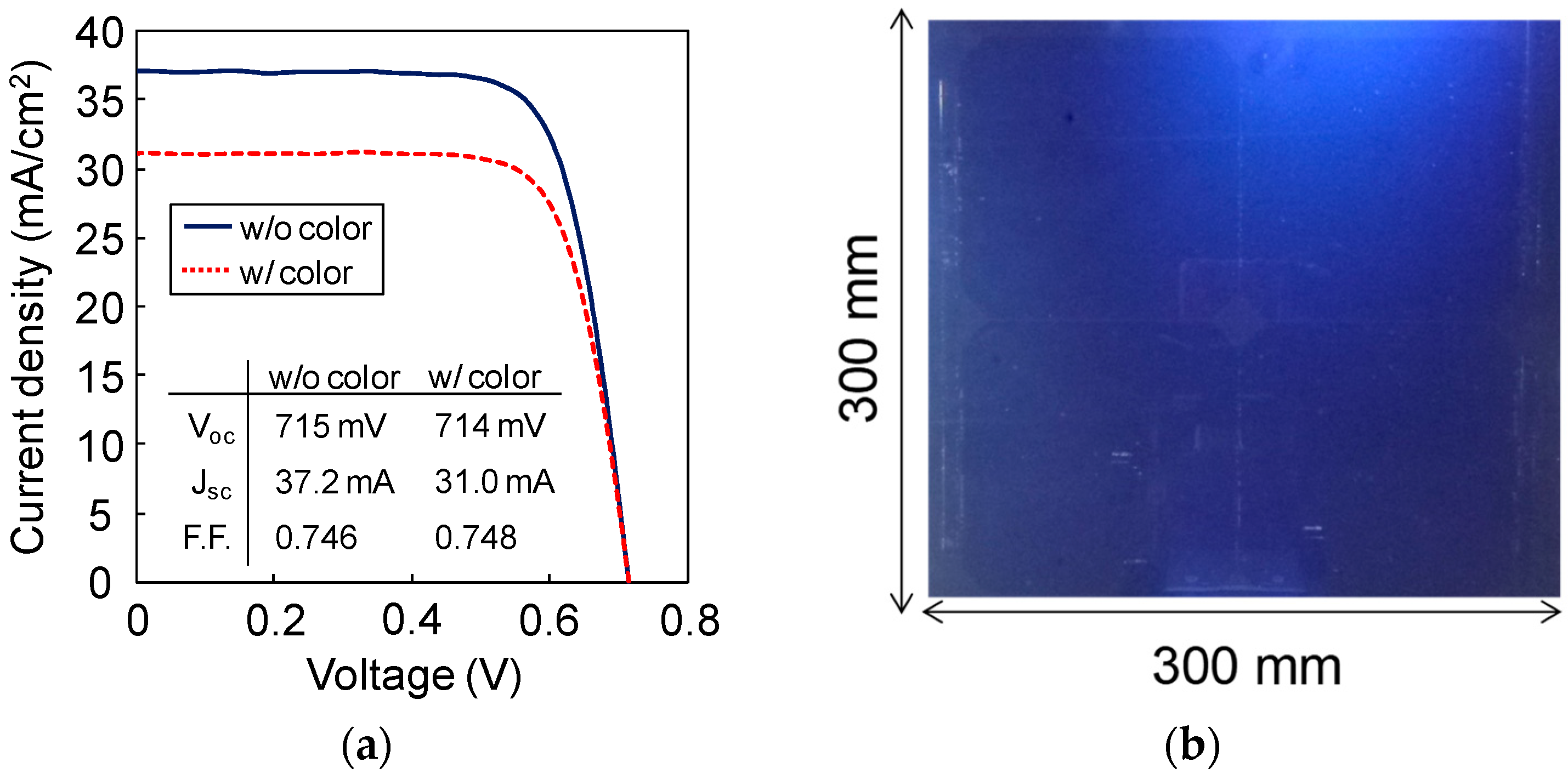
Finally, we fabricated a solar module of size 300 mm × 300 mm, containing four c-Si solar cells, and coated with 10% PWC dilute mica pigment. Figure 6a shows the measured LIV of the solar module with and without the dilute mica pigment. There is no reduction in the open-circuit voltage (Voc) and fill-factor (F.F.), while the short-circuit current density (Isc) is decreased by 15% owing to the generation of the blue color, as expected from Figure 3a. Thus, the output power decreased by 15% by adding the blue color.
Figure 6b is an image of the fabricated solar module with the 10% PWC dilute mica pigment. The dilute mica pigment provides a bright appearance and solid color, similar to the appearance of the standard exterior of mass-produced cars. The photo also shows that the dilute mica pigment provides uniform and consistent colors throughout the fabricated area (300 × 300 mm2), which is essential for achieving a high-quality finish. In addition to providing excellent appearance, the dilute mica pigment retains more than 80% of the output power, compared to the original module without color.
Thus, we conclude that semi-transparent automotive pigments, such as the mica pigment, are promising for coloring solar modules, because they provide the solar module with an excellent appearance as well as maintain a high output power, compared to original solar modules without color. The visual attractiveness of the solar module obtained by the use of automotive mica pigments could considerably increase the installable area of solar modules on cars. In future work, we will investigate the color variations [22] and color matching with a regular car body by changing the thickness and refractive index of the coating metal oxides in the pigments.
4. Conclusions
We presented a high-performance solar module colored using the automotive painting technique. The colored layers consisted of a semi-transparent mica pigment and an automotive clearcoat material, which was coated on a crystalline-Si solar module. Our measurements showed that the dilute mica pigment with ~10% pigment weight concentration is suitable for painting solar modules, because it not only makes the solar module look good, but also retains 80% of the output power compared to the original solar module. We believe that the proposed coloring technique for solar modules can considerably increase the installable area of solar modules on cars.
Author Contributions
Conceptualization, T.M. and D.B.; Methodology, Y.K.; Validation, T.M., Y.K. and D.B.; Formal Analysis, T.M., Y.K. and D.B.; Writing-Original Draft Preparation, T.M.; Writing-Review & Editing, T.M.; Supervision, T.M.
Funding
This research received no external funding.
Conflicts of Interest
The authors declare no conflict of interest.
References
- Light-Duty Automotive Technology, Carbon Dioxide Emissions, and Fuel Economy Trends: 1975 through 2015; EPA-420-R-15-016; United States Environmental Protection Agency: Washington, DC, USA, December 2015.
- Light-Duty Automotive Technology, Carbon Dioxide Emissions, and Fuel Economy Trends: 1975 through 2017; EPA-420-R-18-001; United States Environmental Protection Agency: Washington, DC, USA, January 2018.
- Masuda, T.; Araki, K.; Okumura, K.; Urabe, S.; Kudo, Y.; Kimura, K.; Nakado, T.; Sato, A.; Yamaguchi, M. Static concentrator photovoltaics for automotive applications. Sol. Energy 2017, 146, 523–531. [Google Scholar] [CrossRef]
- Klampaftis, E.; Ross, D.; Hardy, D.A.; Scanlan, P.; Richards, B.S. Adding colour and opening-up graphic design possibilities for photovoltaic modules in the urban landscape. In Proceedings of the 28th European Photovoltaic Solar Energy Conference and Exhibition, Villepinte, France, 30 September–4 October 2013. [Google Scholar]
- Masuda, T.; Araki, K.; Okumura, K.; Urabe, S.; Kudo, Y.; Kimura, K.; Nakado, T.; Sato, A.; Yamaguchi, M. Next environment-friendly cars: Application of solar power as automobile energy source. In Proceedings of the 43rd Photovoltaic Specialists Conference (PVSC 2016), Portland, OR, USA, 5–10 June 2016. [Google Scholar]
- Otaka, H.; Kira, M.; Yano, K.; Ito, S.; Mitekura, H.; Kawata, T.; Matsui, F. Multi-colored dye-sensitized solar cells. J. Photochem. Photobiol. A Chem. 2004, 164, 67–73. [Google Scholar] [CrossRef]
- Arinze, E.S.; Qui, B.; Palmquist, N.; Cheng, Y.; Lin, Y.; Nyirjesy, G.; Qian, G.; Thon, S.M. Color-tuned and transparent colloidal quantum dot solar cells via optimized multilayer interference. Opt. Exp. 2017, 25, A101–A112. [Google Scholar] [CrossRef] [PubMed]
- Park, H.J.; Xu, T.; Lee, J.; Ledbetter, A.; Guo, L. Photonic color filters integrated with organic solar cells for energy harvesting. ACS Nano 2011, 5, 7055–7060. [Google Scholar] [CrossRef] [PubMed]
- Lee, K.; Lee, J.; Seo, S.; Guo, L. Colored ultrathin hybrid photovoltaics with high quantum efficiency. Light Sci. Appl. 2014, 3, e215. [Google Scholar] [CrossRef]
- Galagan, Y.; Debije, M.G; Blom, P.W.M. Semitransparent organic solar cells with organic wavelength dependent reflectors. Appl. Phys. Lett. 2011, 98, 043302. [Google Scholar] [CrossRef] [Green Version]
- Zhang, W.; Anaya, M.; Lozano, G.; Calvo, M.E.; Johnston, M.B.; Míguez, H. Highly efficient perovskite solar cells with tunable structural color. Nano Lett. 2015, 15, 1698–1702. [Google Scholar] [CrossRef] [PubMed]
- Lee, K.-T.; Fukuda, M.; Joglekar, S.; Guo, L. Colored, see-through perovskite solar cells employing an optical cavity. J. Mater. Chem. C Mater. Opt. Electron. Devices 2015, 3, 5377–5382. [Google Scholar] [CrossRef]
- Quiroz, C.O.R.; Bronnbauer, C.; Levchuk, I.; Hou, Y.; Brabec, C.J.; Forberich, K. Coloring semitransparent perovskite solar cells via dielectric mirrors. ACS Nano 2016, 10, 5104–5112. [Google Scholar] [CrossRef] [PubMed]
- Krantz, J.; Stubhan, T.; Richter, M.; Spallek, S.; Litzov, I.; Matt, G.J.; Spiecker, E.; Brabec, C.J. Spray-coated silver nanowires as top electrode layer in semitransparent P3HT:PCBM-based organic solar cell devices. Adv. Funct. Mater. 2013, 23, 1711–1717. [Google Scholar] [CrossRef]
- Lee, Y.-Y.; Tu, K.-H.; Yu, C.-C.; Li, S.-S.; Hwang, J.-Y.; Lin, C.-C.; Chen, K.-H.; Chen, L.-C.; Chen, H.-L.; Chen, C.-W. Top laminated graphene electrode in a semitransparent polymer solar cell by simultaneous thermal annealing/releasing method. ACS Nano 2011, 5, 6564–6570. [Google Scholar] [CrossRef] [PubMed]
- Akafuah, N.K; Poozesh, S.; Salaimeh, A.; Patrick, G.; Lawler, K.; Saito, K. Evolution of the automotive body coating process—A review. Coatings 2016, 6, 24. [Google Scholar] [CrossRef]
- Streitberger, H.J.; Dössel, K.F. Automotive Paints and Coatings; Wiley-VCH Verlag GmbH & Co. KGaA: Weinheim, Germany, 2008. [Google Scholar]
- Kudo, Y.; Sato, A.; Kimura, K.; Iwamoto, S.; Ohba, H.; Sakabe, M.; Shirai, Y. Solar module laminated constitution for automobiles. In Proceedings of the SAE 2016 World Congress and Exhibition, Detroit, MI, USA, 12–14 April 2016. [Google Scholar]
- Banerjee, D.; Zhang, M. Omnidirectional structural color. In Proceedings of the Optical Interference Coatings 2010, Tucson, AZ, USA, 6–11 June 2010. [Google Scholar]
- Hunter, R.S. Photoelectric color-difference meter. J. Opt. Soc. Am. 1958, 48, 985–995. [Google Scholar] [CrossRef]
- Azimi, M.; Boitard, R.; Nasiopoulos, P.; Pourazad, M.T. Visual color difference evaluation of standard color pixel representations for high dynamic range video compression. In Proceedings of the 2017 25th European Signal Processing Conference (EUSIPCO), Kos, Greece, 28 August–2 September 2017. [Google Scholar]
- Masuda, T.; Hirai, S.; Inoue, M.; Chantana, J.; Kudo, Y.; Minemoto, T. Colorful, flexible, and light-weight Cu(In,Ga)Se2 solar cell by lift-off process with automotive painting. IEEE J. Photovolt. 2018. [Google Scholar] [CrossRef]
Figure 1.
(a) Schematic of the c-Si solar module used in this study, which was originally developed for automotive application; and (b) Photo of the fabricated solar module with four solar cells.
Figure 1.
(a) Schematic of the c-Si solar module used in this study, which was originally developed for automotive application; and (b) Photo of the fabricated solar module with four solar cells.

Figure 2.
(a–c) Images of the dilute mica pigment coated on a glass plate with varying PWCs; (d–f) Optical microscope images of the dilute mica pigment; (g) Schematic cross-sectional view of the fabricated sample. The black arrow represents incident light, while the blue arrow represents the light reflected by the pigment.

Figure 3.
Measured transmittance and reflection of the color layer on the quartz plate as a function of PWC using (a) mica pigment and (b) OSC pigment.
Figure 3.
Measured transmittance and reflection of the color layer on the quartz plate as a function of PWC using (a) mica pigment and (b) OSC pigment.

Figure 4.
Measured ΔE between the cell region and backsheet region as a function of PWC.

Figure 5.
Measured relative output power of the colored solar module with the dilute mica and OSC pigments, as a function of PWC.
Figure 5.
Measured relative output power of the colored solar module with the dilute mica and OSC pigments, as a function of PWC.

Figure 6.
(a) Measured solar module characteristics with and without the dilute mica pigment with 10% PWC. (b) Photo of the fabricated solar module with 10% PWC dilute mica pigment.
Figure 6.
(a) Measured solar module characteristics with and without the dilute mica pigment with 10% PWC. (b) Photo of the fabricated solar module with 10% PWC dilute mica pigment.

© 2018 by the authors. Licensee MDPI, Basel, Switzerland. This article is an open access article distributed under the terms and conditions of the Creative Commons Attribution (CC BY) license (http://creativecommons.org/licenses/by/4.0/).
Share and Cite
MDPI and ACS Style
Masuda, T.; Kudo, Y.; Banerjee, D. Visually Attractive and High-Power-Retention Solar Modules by Coloring with Automotive Paints. Coatings 2018, 8, 282. https://doi.org/10.3390/coatings8080282
AMA Style
Masuda T, Kudo Y, Banerjee D. Visually Attractive and High-Power-Retention Solar Modules by Coloring with Automotive Paints. Coatings. 2018; 8(8):282. https://doi.org/10.3390/coatings8080282
Chicago/Turabian StyleMasuda, Taizo, Yuki Kudo, and Debasish Banerjee. 2018. "Visually Attractive and High-Power-Retention Solar Modules by Coloring with Automotive Paints" Coatings 8, no. 8: 282. https://doi.org/10.3390/coatings8080282
Note that from the first issue of 2016, this journal uses article numbers instead of page numbers. See further details here.