The Tribocorrosion and Corrosion Properties of Thermally Oxidized Ti6Al4V Alloy in 0.9 wt.% NaCl Physiological Saline

1
School of Mechanical and Automotive Engineering, Qingdao University of Technology, Qingdao 266033, China
2
State Key Laboratory of Solid Lubrication, Lanzhou Institute of Chemical Physics, Chinese Academy of Sciences, Lanzhou 730000, China
3
Key Laboratory of Marine New Materials and Related Technology, Zhejiang Key Laboratory of Marine Materials and Protection Technology, Ningbo Institute of Material Technology and Engineering, Chinese Academy of Sciences, Ningbo 315201, China
*
Author to whom correspondence should be addressed.
Coatings 2018, 8(8), 285; https://doi.org/10.3390/coatings8080285
Submission received: 13 June 2018
/
Revised: 9 August 2018
/
Accepted: 12 August 2018
/
Published: 16 August 2018
(This article belongs to the Special Issue Nanocomposite Coatings)
Abstract
:Thermal oxidation of Ti6Al4V was carried out at 700 °C for 5 h in air atmosphere. The characteristics of morphology and structure, micro-hardness, and tribocorrosion behavior in 0.9 wt.% NaCl solution of thermally oxidized Ti6Al4V alloys were investigated and compared with those of the untreated one. The scanning electron microscope (SEM) and glow discharge spectrometer (GDS) results reveal that the oxide layer is completely coated on the substrate, which is a bilayer structure consisted of oxide film and oxygen diffusion zone (ODZ). X-ray diffraction (XRD) and Raman measurements reveal the rutile phase as the dominant phase. The micro-hardness and surface roughness (Ra) increase about 1.63 and 4 times than those of the untreated one. Thermally oxidized sample obtains corrosion and tribocorrosion resistance property in 0.9 wt.% NaCl solution. The corrosion potential has a more than 500 mV anodic shift, the corrosion current density decreases about 80%. The total material loss volume is reduced by almost an order of magnitude under tribocorrosion behavior, which is due to the improvement of the micro-hardness of the oxide layer and ODZ that reduce the corrosion and the synergistic effect of corrosion and wear.
1. Introduction
Biomedical devices are often suffering the rotational and sliding action between two articulating surfaces during their service in the vivo environment. Serious damage on their surfaces may result from localized stresses at the contact regions. Additionally, wear rate of the implant surface will remarkably increase due to the synergistic effect of corrosion and corrosion assisted wear in the human body. Titanium and titanium alloys are important biomedical materials due to their excellent properties such as high specific strength, high anti-corrosion property, and good biocompatibility [1,2,3,4,5]. The excellent anti-corrosion property of titanium alloy in a corrosive medium is attributed to the several nanometers naturally formed passive TiO2 film. However, this thin layer is fragile and easily fractured under fretting and sliding wear conditions, which results in poor corrosion resistance of titanium alloy. The degradation of materials is even accelerated when titanium alloys are used in the case of a tribocorrosion system which combines with wear and corrosion environments.
Surface modification treatments are the effective solutions to improve the surface properties of titanium. Many surface modification methods such as thermal oxidation [6,7,8,9,10,11,12], physical vapor deposition (PVD) [13,14,15,16], chemical vapor deposition (CVD) [17], nitriding [18], oxidizing [19], sol-gel technology [20], and laser surface modification [21,22] have been proposed. Among them, the thermal oxidation treatment is more convenient, economical, and effective in preparing thick, highly crystalline and in situ grown films than the others. The oxide films on titanium have been confirmed to offer enhanced tribological protection in both dry and lubricated conditions. They also provide additional corrosion protection as a physical or chemical barrier layer [23,24,25,26,27,28,29,30,31]. The tribocorrosion behavior of the thermally oxidized commercially pure titanium have been studied before [32,33]. However, more work still needs to be done in order to identify the tribocorrosion mechanism of the more widely used biomaterials (Ti6Al4V), especially after thermal oxidation treatment. The purpose of this work is to identify the relative contribution of the oxide layer and the oxygen diffusion zone (ODZ) on the tribocorrosion behavior of the thermal oxidized Ti6Al4V in 0.9 wt.% NaCl aqueous solution (physiological saline).
2. Materials and Methods
2.1. Materials and Sample Preparation
In this work, the specimen is commercially obtained Ti6Al4V material. The thickness is about 1.5 mm, and both length and width are 31 mm. The chemical composition of Ti6Al4V specimens is listed in Table 1, which is provided by the Boti International Metal Co., Ltd. (Baoji, China). The specimens were polished by 400, 800, 1200 grade sandpaper in sequence, and then these specimens are cleaned in absolute ethyl alcohol and deionized water bath in an ultrasonic cleaner, each progress for 10 min. In the end, they were dried under N2.
Thermal oxidation treatment was carried out in a muffle. The temperature was 700 °C and treatment time was 5 h. The whole treatment was conducted in the air. The heating rate was about 5 °C·min−1. These specimens were then furnace cooled to room temperature (about 25 °C).
2.2. Surface Characterization
Scanning electron microscope (SEM; S-3500N, Hitachi, Tokyo, Japan) with an EDS was used to characterize the micro-structure and elemental composition of the unworn and worn surfaces and to perform the cross-section structure of thermally oxidized specimens. Glow discharge spectrometry (GDA 750HP, Spectruma Analytik GmbH, Hof, Germany) was used to analyze compositional depth profile across the oxidized layer. Micro-Raman (Renishaw Invia Reflex, Renishaw, Wotton-under-Edge, UK) spectrometer measurements were taken to identify the structure of the worn surfaces of thermally oxidized samples with a laser excitation wavelength of 532 nm. The roughness (Ra) was measured by roughness tester (Mitutoyo, SJ-200, Kawasaki, Japan). The cut-off length is 0.8 mm, and the assessment length is 4 mm. These measurements were repeated ten times for each sample, and the average values were regarded as the effective data. The hardness was performed by a nanoindenter (G200, MTS, Eden Prairie, MN, USA) with a Berkovich diamond indenter.
2.3. Electrochemical Corrosion Test
The electrochemical corrosion tests of specimens were evaluated by using a CS350 (Corrtest, Wuhan, China) electrochemical work station. As shown in Figure 1, the reference electrode was an Ag/AgCl electrode (+197 mV versus standard hydrogen electrode), the counter electrode a graphite electrode and the specimen work electrode (4.8 cm2 exposed area). There is no load on the specimen when electrochemical corrosion tests were operating. The electrolyte of all tests was 0.9 wt.% NaCl solution (pH ≈ 7). All tests were repeated three times at room temperature (about 25 °C), and the average values were cited in this article. An electrode stabilization in the electrolyte lasts for 1 h before the electrochemical corrosion test. Subsequently, electrochemical impedance spectroscopy (EIS) measurements were performed at open circuit potential (OCP). The frequency range is from 105 to 10−2 Hz, and the AC amplitude is 10 mV. Finally, a potentiodynamic polarization test was operated starting from −300 mV below OCP in the cathodic zone, ending to 1200 mV above the OCP. The potential scan rate was 1 mV·s−1. The corrosion current densities were determined by the Tafel extrapolation method.
2.4. Tribocorrosion Test
Tribocorrosion tests were performed by a linear reciprocating the ball-on-flat module of tribocorrosive instrument (MFT-EC4000, Lanzhou Huahui Instrument Technology Co., Ltd.,Lanzhou, China). Before the test, the open circuit potential (OCP) was monitored during the 1 h stable time for electrode. From Figure 1, during the test, a Ø6 mm alumina ball (Al2O3, Grade25) slides on the specimen surface immersed in the electrolyte at room temperature (about 25 °C). The reciprocating stroke length was 6 mm, and the sliding frequency was 1 Hz. The normal force was 5 N, which corresponds to a maximum Hertzian contact pressure of 0.64 GPa, calculated based on the contact between the alumina ball and the Ti6Al4V flat surface. The 15 min stabilization (cell reciprocating but no contact) time before sliding test was to create a stable starting point for the samples and the other 15 min stabilization time after sliding test to see the passivation response once sliding had ceased. The sliding test were performed for 1 h. The friction force data were acquired by mechanical sensors and the open circuit potential data were acquired by the three-electrode system. Wear depth and width from each sample were then analyzed using a stylus profilometer (Form Talysurf PGI 800, Taylor Hobson, Leicester, UK) to measure the surface profiles across the wear track at 10 different locations. The total material loss in volume is calculated by the area of cross section of wear track and the stroke length. Wear track morphology was analyzed by SEM.
3. Results and Discussion
3.1. Characterization of Thermally Oxidized Samples
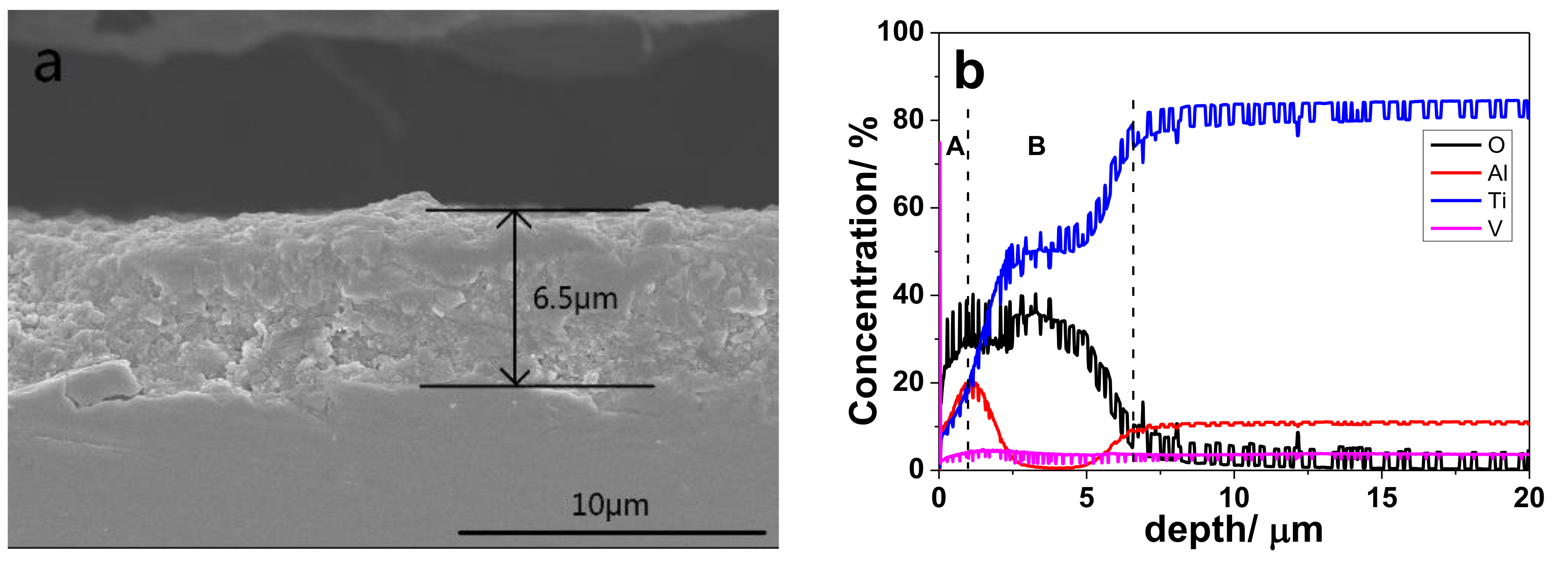
Figure 2 shows the cross-section morphology of the oxidized sample by SEM, together with elements compositional depth profile across the oxidized layer by glow discharge spectrometer (GDS). From Figure 2a, a dense and adherent oxidation structure (~6.5 μm thickness) had formed on the surface of Ti6Al4V sample. As shown in Figure 2b, the oxidation structure is made of an oxidation layer (Section A in Figure 2b) and an oxygen diffusion zone (ODZ) (Section B in Figure 2b) beneath oxidation layer. Thermal oxidation effectively hardens the surface of Ti6Al4V (from 5.1 ± 0.9 to 11.7 ± 1.1 GPa) and leads to an increase in surface roughness (from 0.072 ± 0.007 to 0.275 ± 0.057 μm). Detail structural characterization has been reported in our previous work [34].
3.2. Corrosion Behavior
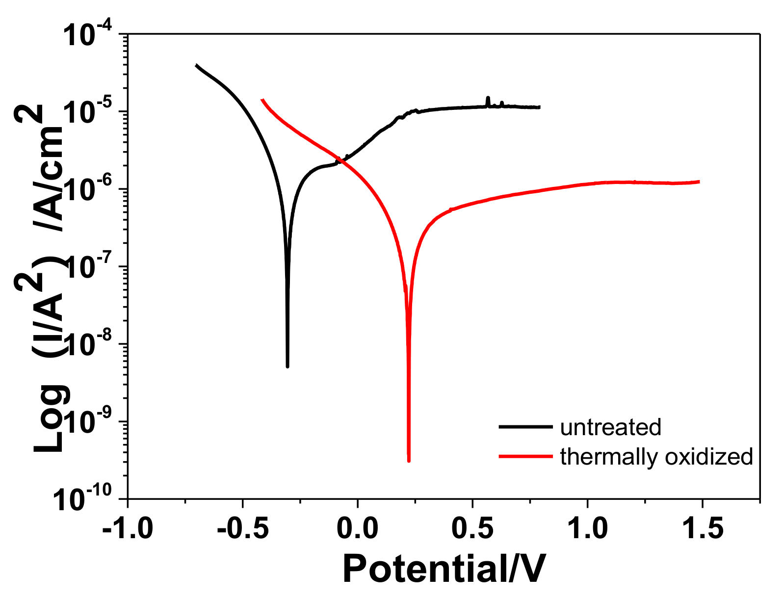
Figure 3 shows the potentiodynamic polarization curves of the two kinds of samples in 0.9 wt.% NaCl solution at room temperature. The corrosion potential (Ecorr) and corrosion current density (Icorr) for specimens tested are given in Table 2. Compared to the thin natural passive oxide film on the untreated samples, the protective oxide film formed by the thermal oxidation process has a more corrosive resistance. The rutile TiO2 has a stable octahedral structure which results in a high thermodynamic stability, thus, Ecorr of the untreated samples was significantly increased after a thermal oxidization process (from −0.3052 to 0.2226 V). Icorr is also lower for thermally oxidized samples (1.68 × 10⁻⁶ vs. 3.86 × 10⁻⁷ A·cm−2). This is because the thermal oxidation process is accompanied by forming a thicker protective oxide film which acts as a barrier, separating the substrate and the corrosive medium or extending the time corrosive medium meets the substrate [24,25]. Compared to the Ecorr of TiO2 layer deposited by atomic layer deposition and anodic oxidation [26,27], the larger value is observed after thermal oxidation. It could be due to different TiO2 structure prepared by these methods.
The EIS technique is also used to further investigate the corrosion characteristic for thermally oxidized sample in 0.9 wt.% NaCl solution at OCP. Due to the depression effects caused by the asperity of the samples surface, the semicircles of the plots shift to the quadrant IV. The diameter of the semicircle partly implies the corrosive resistance property. The semi-circle of thermally oxidized sample in Figure 4a shows a higher diameter, indicating the higher corrosion resistance than the untreated one.
According to other investigations [35,36], a porous outer layer and a dense inner layer make up the bi-layered oxide passive film on untreated sample in electrolyte. Therefore, due to cumulative capacitive effect of more than one time constant, a broad peak over a large range of frequency is shown in the Bode phase spectra (Figure 4b) for the untreated sample. The Bode phase spectra of thermally oxidized sample showed two obvious time constants. As to the two kinds of samples, the time constant at low frequencies could be related to the inner layer contacting with the substrate, and the one at high frequencies to outer layer. The peak of phase angle for untreated sample was close to −90°, indicating a good capacitive behavior [37] of the passive film, while the peaks for the thermally oxidized sample was about −50°.
It is clear that the impedance module value of thermally oxidized sample was always larger than that of the untreated sample at both low and high frequencies, which can be observed in the Bode impedance plot (Figure 4c). This could suggest the better corrosion behavior for thermally oxidized sample than untreated one, as previously indicated by the polarization curves in Figure 3 and Table 2.
As to the bilayer structure of samples, the EIS data were simulated by a relevant equivalent circuit as shown in Figure 4d. Table 3 list the electrochemical parameters fitted from the simulations results. The chi-square (χ2) of less than 0.01 indicated the EIS data adjusted well to the proposed equivalent circuit [38]. The model is consisted of resistance elements for solution (Rs), resistance elements for outer layer (Rout, porous layer of untreated sample and TiO2 layer of thermally oxidized layer), resistance elements for inner layer (Rin, dense inner layer of untreated sample and ODZ layer of thermally oxidized layer) and constant phase elements (Qin, Qout) for the capacitance of outer and inner layer.
The constant phase elements (Qin and Qout) are represented by the non-ideal capacitor which is associated with the non-uniform distribution of current as a result of roughness and surface defects. The impedance of a constant phase element is defined as Q = [C(jw)n]−1, where −1 ≤ n ≤ 1. The value of n specifies the deviation of CPE from an ideal capacitor. The value is closer to 1, implying that the CPE is less deviated from an ideal capacitor [39]. As listed in Table 3, the values of nin and nout of the untreated sample were closer to 1 than those for the thermally oxidized one, revealing a more ideal capacitive behavior for the untreated sample. This was due to a lower surface roughness (Ra = ~0.072 ± 0.007 μm) of the untreated sample, as compared with Ra of 0.275 ± 0.057 μm for the thermally oxidized one. It has been known that the layer’s thickness is inversely related to the calculated capacitance (Q) [40,41]. The thicker layer is formed on the substrate, the harder corrosive ions penetrate throughout, resulting in more corrosion-resistant performance. According to the simulated results, the higher thickness of the inner and outer layer of the thermally oxidized sample is formed compared with the untreated sample. Meanwhile, the resistance of the inner and outer layer of the thermally oxidized sample were also higher than the untreated one, representing better protective film properties and a higher corrosion resistance. However, the resistance of TiO2 formed by thermal oxidation is lower than other methods such as ALD and anodic oxidation [26,27].
3.3. Tribocorrosion Behavior
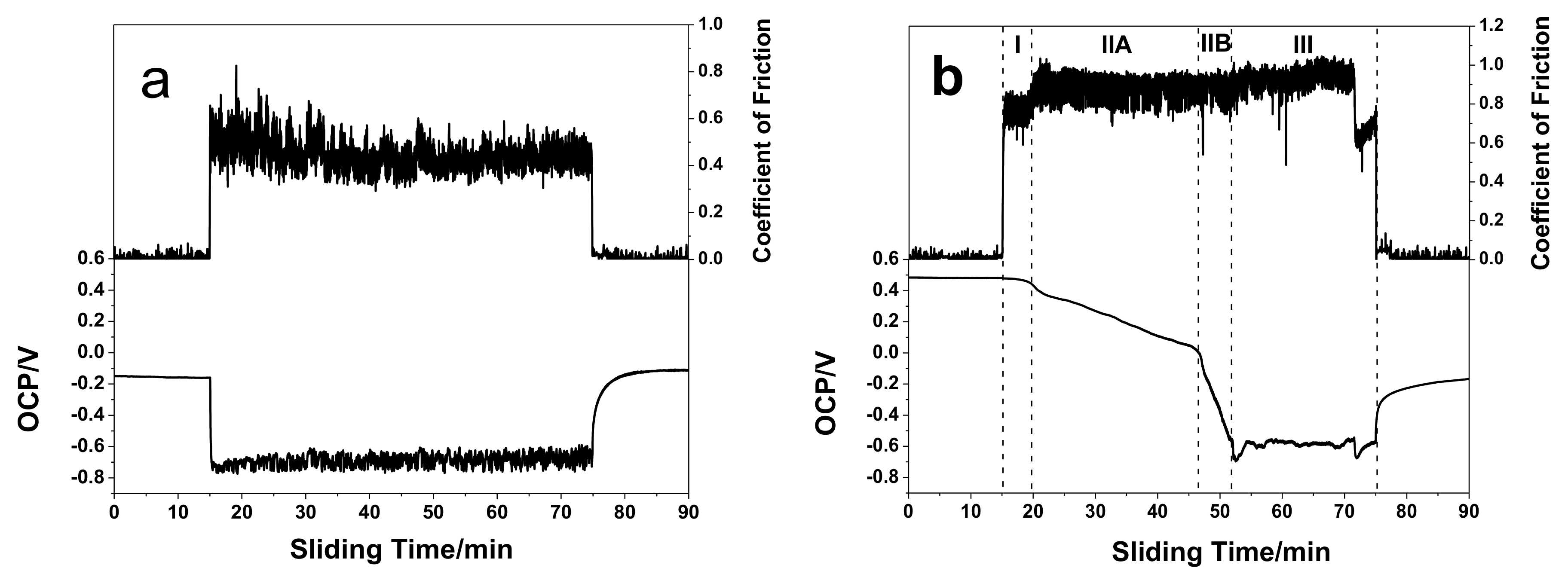
The evolution of open circuit potential (OCP) as sliding time in 0.9 wt.% NaCl solution is shown in Figure 5. The evolution of the coefficient of friction (COF) with sliding time is also shown. OCP stabilized after first 15 min of immersion of untreated and thermally oxidized samples, indicating that a stable electrochemical condition at the surface is achieved. OCP values of around −152 mV and 484 mV are showed for untreated sample and thermally oxidized samples. Higher OCP are related to nobler characteristics of materials, which demonstrate the improvement of corrosion tendency for untreated sample after thermally oxidized treatment.
For untreated sample in Figure 5a, a sudden decrease of the OCP was observed when rubbing starts. The OCP drops to a lower value of −740 mV and is fluctuating in phase with the reciprocating motion of the alumina ball. In the same time, COF jumps to about 0.5. This particular situation indicates that the natural passive film is disrupted or removed from the surface due to the rubbing action of the alumina counter body. Therefore, the fresh active Ti6Al4V substrate becomes exposed to the electrolyte in the sliding track, which results in the drop in OCP. During sliding, there is a small oscillation in OCP, which is from depassivation/passivation phenomena during the successive contact events. COF was observed to be stable at value of about 0.43 throughout whole sliding period. Once rubbing ceased, the OCP progressively increases to a high value for a steady state, indicating a progressive passivation of the wear track area.
In the case of the thermally oxidized sample in Figure 5b, a monotonic decrease in the OCP almost is observed at a rate much slower than untreated sample as soon as sliding starts. The OCP remains constant and starts to decrease after about 5 min of sliding. Correspondingly, there is the same gradual increase in COF after about 5 min sliding. After approximately 40 min of sliding, the OCP reaches a low value of about −600 mV, whereas COF remains at about 0.85. Just before the end of sliding, OCP increases to high value and COF sharply decreases to about 0.65. After sliding creases, the OCP reached to a high value of −200 mV, which is at level of untreated samples, but more than 600 mV lower than original OCP for thermally oxidized sample.
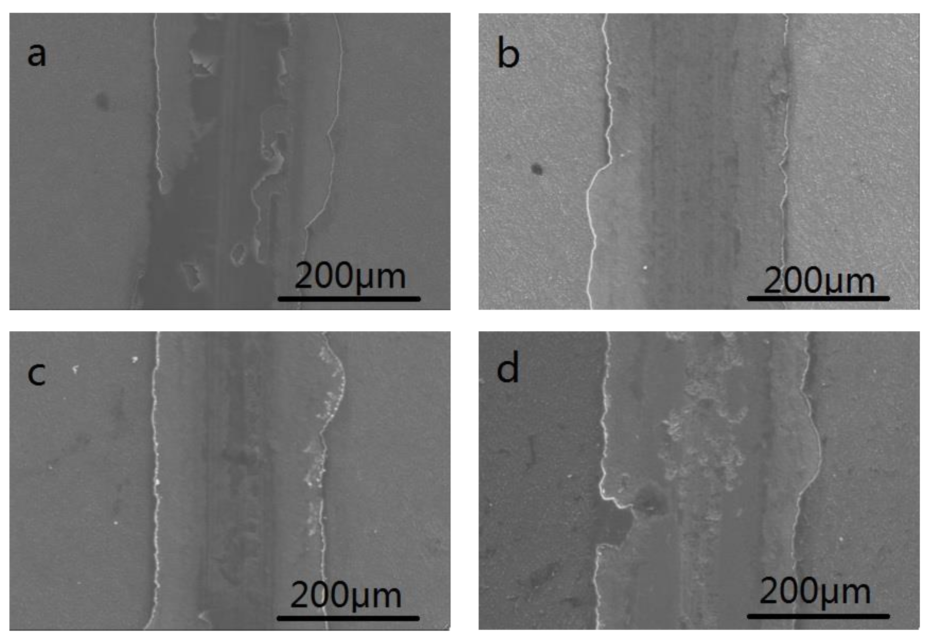
Figure 6 shows SEM image of worn scar and surface profiles which are measured across the wear tracks for untreated and thermally oxidized samples after tribocorrosion test. The surfaces of the wear track from the untreated sample presents a roughened surface with excessive plastically deformed features along with abrasive grooves, which is representative adhesive and abrasive wear. The wear tracks from thermally oxidized samples seem smoother, resulting from the higher hardness and strength of thermally oxidized sample that could enable the material to deform difficultly during tribocorrosion. The plastically deformed features and abrasive grooves on the wear surface of untreated sample lead to a larger effective surface area exposed to the corrosive medium which results in accelerated corrosion during wear process. Therefore, the wear volume of untreated sample is much larger than the thermally oxidized one.
EDS analysis of the wear surface of both samples are listed in Table 4. The oxygen content of untreated sample is kept in a low level both outside (region 1 in Figure 6a) and inside (region 2 in Figure 6a) of wear surface, suggesting the protective film is only the thin and weak natural passive film and passive film after sliding. However, for the thermally oxidized one, the oxygen content is still in a relatively high level in the most part of wear scar (region 2 in Figure 6b), indicating the most part of substrate is under the protection of oxidized diffusion zone. Nevertheless, region 3, on the fractured area in Figure 6b, shows lower oxygen content, implying the oxygen diffusion zone is also removed a little at the end of sliding.
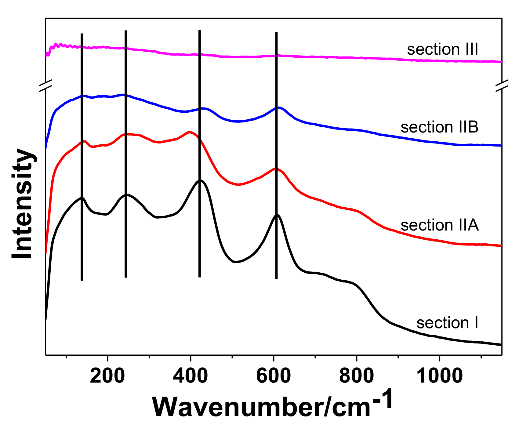
The thermally oxidized sample shows different OCP and COF evolution as sliding time, as shown in Figure 5b, when comparing to the untreated sample. The OCP and COF data can give the real-time status of samples surface chemistry of oxide layer. According to the OCP and COF curve, the tribocorrosion test can be divide into three sections on the basis of the surface state: (I) oxide film; (II) removal of oxide film and exposure of ODZ; and (III) removal of ODZ and exposure of substrate. Each section exhibits a unique OCP and COF response.
In section I, the OCP remained constant at 483 mV owing to the protection of oxide film, and the COF was about 0.75, which is larger than 0.43 for untreated sample. According to Figure 7a, for the SEM image of wear scar, the oxide film was not worn through and partly maintains its integrity. The similar result can also be obtained by the Raman spectra in Figure 8.
Subsequently, the OCP dropped from 483 to −600 mV in section II, while COF increased to approximately 0.85. In this section, the oxide film began to be removed and ODZ is exposed gradually. This section can be separated into two sub-sections, section IIA and section IIB, on the basis of the drop rate of OCP. In section IIA, due to the relatively high oxygen concentration in the top section of ODZ, the rate of passivation is equal to or little slower than the rate of depassivation. Therefore, the dominant part on the surface may be oxide film. This is proved by the SEM image of worn scar as shown in Figure 7b. The OCP dropped at a relatively slow rate. However, with the rubbing continuing, the worn behavior occurred in the bottom section of ODZ. Due to the relatively low oxygen concentration, the rate of passive film regeneration is much slower than the rate of depassivation. More and more cracks and scars occur in the center area of wear track. An electric coupling can be formed between the exposed ODZ and oxide film. This may accelerate the rate of removal of oxide film, which results in the higher drop rate of OCP. Therefore, ODZ turns to be the main composition in section IIB, as shown in Figure 6c for SEM image of worn scar. As shown is Figure 8, the intensity of Raman peaks become weaker with the sliding process, suggesting the removal behavior of the oxide layer.
In section III, full exposure of the ODZ to sliding contact results in a large cathodic shift of OCP, the OCP value rapidly goes down to about −680 mV. Then, the OCP is gradually shifted from −680 to −580 mV and fluctuated around it.
This is due to a thin passive film formation in the ODZ wear track. In the same time, COF maintains the similar value in the prior period. However, in the last 5 min of this section, there is an obvious reduction in COF and another cathodic shift in OCP, implying that some substrate is exposed in the electrolyte. The situation could be clearly observed in the center section of worn scar as shown in Figure 7d. The Raman peaks of this region in Figure 8 is almost disappeared, implying the exposure of Ti6Al4V substrate.
3.4. Material Loss Volume
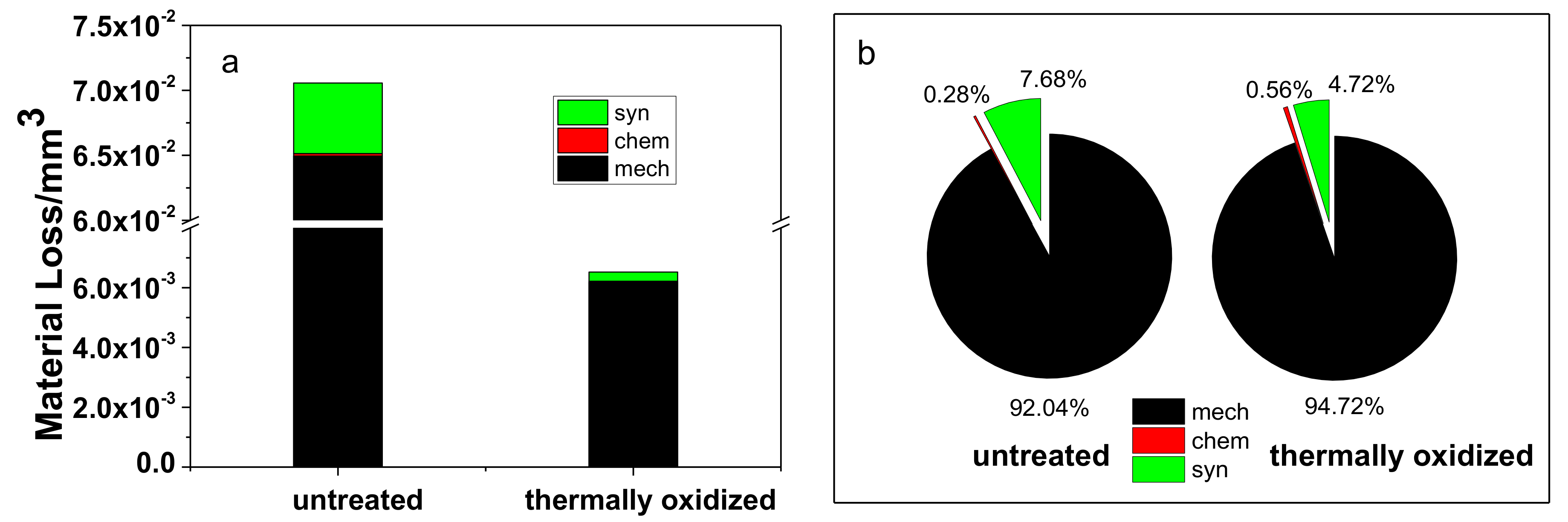
Morphology of the wear track was measured using a profilometer. The material loss volume was calculated by the area of wear track multiplied with stroke length. The results are shown in Table 5. The material loss volume (Vtotal) is a sum of mechanical (Vmech), chemical (Vchem) volume losses and synergistic effect volume losses, i.e.,:
Vtotal = Vmech + Vchem + Vsyn
The contribution of chemical wear in the tribocorrosion process is determined by Faraday’s law. The current can be obtained from the polarization curve and tribocorrosion test.
where I is the average current (A) developed during sliding contact or in static corrosion condition, t is the time (s) of sliding contact, F is Faraday’s constant (965,000 C·mol−1), M is the atomic mass of the metal (45.87 g·mol−1 for Ti), n is the charge number for the oxidation reaction (valance = +3.93 for Ti), and ρ is the density of the metal (4.42 g·cm−3).
Vchem = (ItM)/(nFρ)
From Table 5 and Figure 9, thermal oxidation reduces the material loss volume as compared to untreated sample by an order of magnitude at OCP when mechanical wear is predominant. Due to the anti-corrosion property of the oxide film and OZD layer, the material losses of corrosion and synergistic effect reduces a lot and the rate of corrosion and synergistic effect in the total material losses also reduces to about 5%. The material loss is almost caused by mechanical wear. At the same time, the micro-hardness is enhanced by the thermally oxidized treatment. This may be the major reason which results in the reduction of material loss. During the tribocorrosion period, the oxide film offers the protection against corrosion and wear. Once the oxide film has been removed, the ODZ can play the similar role.
4. Conclusions
The oxide structure formed by thermal oxidation improves the anti-corrosion property of Ti6Al4V by reducing corrosion current density and increasing corrosion potential. The corrosion potential has a more than 500 mV anodic shift, the corrosion current density decreases about 80%. During sliding action at OCP in electrolyte for the thermally oxidized sample, three sections can be divided by the typical friction curve and potential. Each section has its own characteristics corresponding to the oxide layer, the gradual or partial removal of the oxide layer, the diffusion zone, and the substrate. The anti-corrosive oxide layer and ODZ enhance the micro-hardness of the surface and reduce the corrosion and the synergistic effect of corrosion and wear. These can also decrease the mechanical wear. Therefore, the total material loss volume of thermally oxidized Ti6Al4V is reduced by almost an order of magnitude as comparing with untreated one.
Author Contributions
Conceptualization, L.C., J.P. and Y.W.; Methodology, L.C.; Software, L.C.; Validation, L.C.; Formal Analysis, L.C.; Investigation, L.C.; Resources, L.C., J.P. and Y.W.; Data Curation, L.C.; Writing-Original Draft Preparation, L.C.; Writing-Review & Editing, J.P., Y.W. and S.Y.; Visualization, L.C.; Supervision, Y.W.; Project Administration, Y.W.; Funding Acquisition, Y.W., L.C., and J.P.
Funding
This research was funded by National Natural Science Foundation of China (51375249, U1737214), Natural Science Foundation of Shandong Province (ZR2017PEE013) and Key Research & Development Plan of Shandong Province (2017GSF220012).
Conflicts of Interest
The authors declare no conflict of interest.
References
- Barao, V.A.; Mathew, M.T.; Assuncao, W.G.; Yuan, J.C.C.; Wimmer, M.A.; Sukotjo, C. Stability of cpTi and Ti6Al4V alloy for dental implants as a function of saliva pH—An electrochemical study. Clin. Oral Implants Res. 2012, 23, 1055–1062. [Google Scholar] [CrossRef] [PubMed]
- Faria, A.C.L.; Rodrigues, R.C.S.; Claro, A.P.R.A.; de Mattos, M.D.G.C.; Ribeiro, R.F. Wear resistance of experimental titanium alloys for dental applications. J. Mech. Behav. Biomed. 2011, 4, 1873–1879. [Google Scholar] [CrossRef] [PubMed]
- Licausi, M.P.; Muñoz, A.I.; Borrás, V.A. Influence of the fabrication process and fluoride content on the tribocorrosion behaviour of Ti6Al4V biomedical alloy in artificial saliva. J. Mech. Behav. Biomed. 2013, 20, 137–148. [Google Scholar] [CrossRef] [PubMed]
- Rack, H.J.; Qazi, J.I. Titanium alloys for biomedical applications. Mat. Sci. Eng. C 2006, 26, 1269–1277. [Google Scholar] [CrossRef]
- Yadroitsev, I.; Krakhmalev, P.; Yadroitsava, I. Selective laser melting of Ti6Al4V alloy for biomedical applications: Temperature monitoring and microstructural evolution. J. Alloy. Compd. 2014, 583, 404–409. [Google Scholar] [CrossRef]
- Dearnley, P.A.; Dahm, K.L.; Çimenoǧlu, H. The corrosion-wear behaviour of thermally oxidised CP-Ti and Ti6Al4V. Wear 2004, 256, 469–479. [Google Scholar] [CrossRef]
- Guleryuz, H.; Cimenoglu, H. Effect of thermal oxidation on corrosion and corrosion-wear behaviour of a Ti6Al4V alloy. Biomaterials 2004, 25, 3325–3333. [Google Scholar] [CrossRef] [PubMed]
- Guleryuz, H.; Cimenoglu, H. Oxidation of Ti6Al4V alloy. J. Alloy. Compd. 2009, 472, 241–246. [Google Scholar] [CrossRef]
- Kumar, S.; Narayanan, T.S.; Raman, S.G.S.; Seshadri, S.K. Thermal oxidation of Ti6Al4V alloy: Microstructural and electrochemical characterization. Mater. Chem. Phys. 2010, 119, 337–346. [Google Scholar] [CrossRef]
- Azadeh, A.; Ashrafizadeh, F. Structural features and corrosion analysis of thermally oxidized titanium. J. Alloy. Compd. 2009, 480, 849–852. [Google Scholar] [CrossRef]
- Wang, S.; Liu, Y.; Zhang, C.; Liao, Z.; Liu, W. The improvement of wettability, biotribological behavior and corrosion resistance of titanium alloy pretreated by thermal oxidation. Tribol. Int. 2014, 79, 174–182. [Google Scholar] [CrossRef]
- Wang, S.; Liao, Z.; Liu, Y.; Liu, W. Influence of thermal oxidation temperature on themicrostructural and tribological behavior of Ti6Al4V alloy. Surf. Coat. Technol. 2014, 240, 470–477. [Google Scholar] [CrossRef]
- Marin, E.; Offoiach, R.; Regis, M.; Fusi, S.; Lanzutti, A.; Fedrizzi, L. Diffusive thermal treatments combined with PVD coatings for tribological protection of titanium alloys. Mater. Des. 2016, 89, 314–322. [Google Scholar] [CrossRef]
- Rahmati, B.; Sarhan, A.A.; Zalnezhad, E.; Kamiab, Z.; Dabbagh, A.; Choudhury, D.; Abas, W.A.B.W. Development of tantalum oxide (TaO) thin film coating on biomedical Ti-6Al-4V alloy to enhance mechanical properties and biocompatibility. Ceram. Int. 2016, 42, 466–480. [Google Scholar] [CrossRef]
- Oliveira, V.M.C.A.; Aguiar, C.; Vazquez, A.M.; Robin, A.; Barboza, M.J.R. Improving corrosion resistance of Ti6Al4V alloy through plasma-assisted PVD deposited nitride coatings. Corros. Sci. 2014, 88, 317–327. [Google Scholar] [CrossRef]
- Mohseni, E.; Zalnezhad, E.; Bushroa, A.R.; Hamouda, A.M.; Goh, B.T.; Yoon, G.H. Ti/TiN/HA coating on Ti–6Al–4V for biomedical applications. Ceram. Int. 2015, 41, 14447–14457. [Google Scholar] [CrossRef]
- Kessler, O.; Surm, H.; Hoffmann, F.; Mayr, P. Enhancing surface hardness of titanium alloy Ti6Al4V by combined nitriding and CVD coating. Surf. Eng. 2002, 18, 299–304. [Google Scholar] [CrossRef]
- Sathish, S.; Geetha, M.; Pandey, N.D.; Richard, C.; Asokamani, R. Studies on the corrosion and wear behavior of the laser nitrided biomedical titanium and its alloys. Mater. Sci. Eng. C 2010, 30, 376–382. [Google Scholar] [CrossRef]
- Fernandes, A.; Vaz, F.; Ariza, E.; Rocha, L.; Ribeiro, A.; Vieira, A.; Rivière, J.; Pichon, L. Tribocorrosion behaviour of plasma nitrided and plasma nitrided + oxidised Ti6Al4V alloy. Surf. Coat. Technol. 2006, 200, 6218–6224. [Google Scholar] [CrossRef]
- Catauro, M.; Bollino, F.; Giovanardi, R.; Veronesi, P. Modification of Ti6Al4V implant surfaces by biocompatible TiO2/PCL hybrid layers prepared via sol-gel dip coating: Structural characterization, mechanical and corrosion behavior. Mater. Sci. Eng. C 2017, 74, 501–507. [Google Scholar] [CrossRef] [PubMed]
- Tian, Y.S.; Chen, C.Z.; Li, S.T.; Huo, Q.H. Research progress on laser surface modification of titanium alloys. Appl. Surf. Sci. 2005, 242, 177–184. [Google Scholar] [CrossRef]
- Vázquez Martínez, J.M.; Salguero Gómez, J.; Batista Ponce, M.; Botana Pedemonte, F.J. Effects of Laser Processing Parameters on Texturized Layer Development and Surface Features of Ti6Al4V Alloy Samples. Coatings 2018, 8, 6. [Google Scholar] [CrossRef]
- Aniołek, K.; Kupka, M.; Barylski, A. Sliding wear resistance of oxide layers formed on a titanium surface during thermal oxidation. Wear 2016, 356, 23–29. [Google Scholar] [CrossRef]
- Bailey, R.; Sun, Y. Unlubricated sliding friction and wear characteristics of thermally oxidized commercially pure titanium. Wear 2013, 308, 61–70. [Google Scholar] [CrossRef]
- Grotberg, J.; Hamlekhan, A.; Butt, A.; Patel, S.; Royhman, D.; Shokuhfar, T.; Sukotjob, C.; Takoudisa, C.; Mathew, M.T. Thermally oxidized titania nanotubes enhance the corrosion resistance of Ti6Al4V. Mater. Sci. Eng. C 2016, 59, 677–689. [Google Scholar] [CrossRef] [PubMed]
- Basiaga, M.; Kajzer, W.; Walke, W.; Kajzer, A.; Kaczmarek, M. Evaluation of physicochemical properties of surface modified Ti6Al4V and Ti6Al7Nb alloys used for orthopedic implants. Mater. Sci. Eng. C 2016, 68, 851–860. [Google Scholar] [CrossRef] [PubMed]
- Basiaga, M.; Szewczenko, J.; Walke, W.; Zbigniew, P.; Magdalena, A.; Agnieszka, H. Electrochemical properties of TiO2 oxide layer deposited on Ti6Al7Nb alloy. Innov. Biomed. Eng. 2017, 526, 3–10. [Google Scholar] [CrossRef]
- Jamesh, M.; Kumar, S.; Narayanan, T.S.N.; Chu, P.K. Effect of thermal oxidation on the corrosion resistance of Ti6Al4V alloy in hydrochloric and nitric acid medium. Mater. Corros. 2013, 64, 902–907. [Google Scholar] [CrossRef]
- Luo, Y.; Chen, W.; Tian, M.; Teng, S.H. Thermal oxidation of Ti6Al4V alloy and its biotribological properties under serum lubrication. Tribol. Int. 2015, 89, 67–71. [Google Scholar] [CrossRef]
- Lin, N.; Li, D.; Zou, J.; Xie, R.; Wang, Z.; Tang, B. Surface Texture-Based Surface Treatments on Ti6Al4V Titanium Alloys for Tribological and Biological Applications: A Mini Review. Materials 2018, 11, 487. [Google Scholar] [CrossRef] [PubMed]
- Martinez, J.M.V.; Pedemonte, F.J.B.; Galvin, M.B.; Gomez, J.S.; Barcena, M.M. Sliding Wear Behavior of UNS R56400 Titanium Alloy Samples Thermally Oxidized by Laser. Materials 2017, 10, 830. [Google Scholar] [CrossRef] [PubMed]
- Arslan, E.; Totik, Y.; Demirci, E.; Alsaran, A. Influence of surface roughness on corrosion and tribological behavior of CP-Ti after thermal oxidation treatment. J. Mater. Eng. Perform. 2010, 19, 428–433. [Google Scholar] [CrossRef]
- Bailey, R.; Sun, Y. Corrosion and tribocorrosion performance of thermally oxidized commercially pure titanium in a 0.9% NaCl solution. J. Mater. Eng. Perform. 2015, 24, 1669–1678. [Google Scholar] [CrossRef]
- Cao, L.; Liu, J.; Wan, Y.; Yang, S.; Gao, J.; Pu, J. Low-friction carbon-based tribofilm from poly-alpha-olefin oil on thermally oxidized Ti6Al4V. Surf. Coat. Technol. 2018, 337, 471–477. [Google Scholar] [CrossRef]
- De Assis, S.L.; Wolynec, S.; Costa, I. Corrosion characterization of titanium alloys by electrochemical techniques. Electrochim. Acta 2006, 51, 1815–1819. [Google Scholar] [CrossRef]
- Du, H.L.; Datta, P.K.; Lewis, D.B.; Burnell-Gray, J.S. Air oxidation behaviour of Ti6Al4V alloy between 650 and 850 °C. Corros. Sci. 1994, 36, 631–642. [Google Scholar] [CrossRef]
- Manhabosco, T.M.; Tamborim, S.M.; dos Santos, C.B.; Müller, I.L. Tribological, electrochemical and tribo-electrochemical characterization of bare and nitrided Ti6Al4V in simulated body fluid solution. Corros. Sci. 2011, 53, 1786–1793. [Google Scholar] [CrossRef]
- Mareci, D.; Chelariu, R.; Ciurescu, G.; Sutiman, D.; Gordin, D.M.; Gloriant, T. Corrosion behaviour of some titanium dental alloys synthesized by cold crucible levitation melting. J. Optoelectron. Adv. Mater. 2010, 12, 1590–1596. [Google Scholar]
- Montemor, M.F.; Ferreira, M.G.S. Electrochemical study of modified bis-[triethoxysilylpropyl] tetrasulfide silane films applied on the AZ31 Mg alloy. Electrochim. Acta 2007, 52, 7486–7495. [Google Scholar] [CrossRef]
- Fazel, M.; Salimijazi, H.R.; Golozar, M.A. A comparison of corrosion, tribocorrosion and electrochemical impedance properties of pure Ti and Ti6Al4V alloy treated by micro-arc oxidation process. Appl. Surf. Sci. 2015, 324, 751–756. [Google Scholar] [CrossRef]
- González, J.E.G.; Mirza-Rosca, J.C. Study of the corrosion behaviour of titanium and some of its alloys for biomedical and dental implant applications. J. Electroanal. Chem. 1999, 471, 109–115. [Google Scholar] [CrossRef]
Figure 1.
The scheme of the corrosion and tribocorrosion instrument.

Figure 2.
(a) Scanning electron microscope (SEM) image of the cross-sectional structure and (b) elements concentration depth profile measured by GDS across oxide structure on oxidized Ti6Al4V samples.
Figure 2.
(a) Scanning electron microscope (SEM) image of the cross-sectional structure and (b) elements concentration depth profile measured by GDS across oxide structure on oxidized Ti6Al4V samples.

Figure 3.
Potentiodynamic polarization curves of untreated and thermally oxidized samples. Sweep rate of 1 mV·s−1, electrolyte: 0.9 wt.% NaCl solution.
Figure 3.
Potentiodynamic polarization curves of untreated and thermally oxidized samples. Sweep rate of 1 mV·s−1, electrolyte: 0.9 wt.% NaCl solution.

Figure 4.
Electrochemical impedance spectroscopy (EIS) results for untreated and thermally oxidized Ti6Al4V sample: (a) NY Quist plots (Z′ and Z″ mean the real part and imaginary part of impedance under different frequency); (b) bode impedance plots (theta mean the phase angle of impedance under different frequency); (c) bode theta-angle plots (lzl mean the module value of impedance under different frequency); and (d) equivalent circuit model.

Figure 5.
Open circuit potential (OCP) and respective friction coefficient curve of (a) untreated and (b) thermally oxidized samples.
Figure 5.
Open circuit potential (OCP) and respective friction coefficient curve of (a) untreated and (b) thermally oxidized samples.

Figure 6.
SEM image of the wear track morphology and profiles of various samples after OCP tribocorrosion test. (a,c) Untreated and (b,d) thermally oxidized samples.
Figure 6.
SEM image of the wear track morphology and profiles of various samples after OCP tribocorrosion test. (a,c) Untreated and (b,d) thermally oxidized samples.

Figure 7.
SEM image of the wear track morphology in different sections of thermally oxidized sample (a) section I, (b) section IIA, (c) section IIB, and (d) section III as shown in Figure 5b.
Figure 7.
SEM image of the wear track morphology in different sections of thermally oxidized sample (a) section I, (b) section IIA, (c) section IIB, and (d) section III as shown in Figure 5b.

Figure 8.
Raman patterns of wear surface of thermally oxidized samples in different stage as shown in Figure 4b.
Figure 8.
Raman patterns of wear surface of thermally oxidized samples in different stage as shown in Figure 4b.

Figure 9.
The (a) bar chart and (b) pie chart of Table 5.
Figure 9.
The (a) bar chart and (b) pie chart of Table 5.


Table 1.
The chemical composition of Ti6Al4V.
| Material | Composition (wt.%) | ||||||
|---|---|---|---|---|---|---|---|
| Ti | Al | V | Zr | Mo | Fe | Ni | |
| Ti6Al4V | 89.740 | 6.188 | 4.067 | <0.100 | <0.100 | <0.100 | 0.005 |
Table 2.
Parameters obtained from potentiodynamic polarization curve in Figure 3.
Table 2.
Parameters obtained from potentiodynamic polarization curve in Figure 3.
| Parameter | Samples | |
|---|---|---|
| Untreated | Thermally Oxidized | |
| Ecorr (V) | −0.3052 | 0.2226 |
| Icorr (A·cm−2) | 1.68 × 10⁻⁶ | 3.86 × 10⁻⁷ |
Table 3.
Electrochemical impedance parameters.
| Sample | Rs (Ω cm2) | Qo (Ssn/cm2) | no | Ro (Ω cm2) | QODZ (Ssn/cm2) | nODZ | RODZ (Ω cm2) |
|---|---|---|---|---|---|---|---|
| Untreated | 514.6 | 8.54 × 10⁻⁵ | 0.906 | 333.1 | 8.46 × 10⁻⁶ | 0.896 | 5.51 × 10⁵ |
| Thermally oxidized | 388.8 | 8.42 × 10⁻⁷ | 0.813 | 1.6 × 10⁴ | 5.02 × 10⁻⁶ | 0.864 | 3.57 × 10⁶ |
Table 4.
The atomic concentration of unworn and worn surface of different samples by EDS.
| Samples | Region 1 | Element (at.%) | |||
|---|---|---|---|---|---|
| Ti | Al | V | O | ||
| Untreated | 1 | 90.31 | 6.01 | 1.16 | 2.52 |
| 2 | 90.13 | 6.53 | 1.32 | 2.02 | |
| Thermally oxidized | 1 | 21.47 | 8.66 | 1.71 | 68.16 |
| 2 | 53.99 | 6.64 | 2.86 | 36.51 | |
| 3 | 86.77 | 8.24 | 2.65 | 2.34 | |
1 The regions are indicated in Figure 6.
Table 5.
Contribution of mechanical wear, corrosion, and synergistic effect to total material loss volume of untreated and thermally oxidized sample.
Table 5.
Contribution of mechanical wear, corrosion, and synergistic effect to total material loss volume of untreated and thermally oxidized sample.
| Contribution | Untreated | Thermally Oxidized Sample | ||
|---|---|---|---|---|
| Material Loss Volume (10−3 mm3) | Proportion of Total Material Loss Volume (%) | Material Loss Volume (10−3 mm3) | Proportion of Total Material Loss Volume (%) | |
| mech | 64.95 ± 1.26 | 92.04 | 6.18 ± 0.16 | 94.72 |
| chem | 0.20 ± 0.02 | 0.28 | 0.04 ± 0.01 | 0.56 |
| syn | 5.42 ± 0.33 | 7.68 | 0.31 ± 0.04 | 4.72 |
| total | 70.57 ± 1.38 | 100 | 6.53 ± 0.19 | 100 |
© 2018 by the authors. Licensee MDPI, Basel, Switzerland. This article is an open access article distributed under the terms and conditions of the Creative Commons Attribution (CC BY) license (http://creativecommons.org/licenses/by/4.0/).
Share and Cite
MDPI and ACS Style
Cao, L.; Wan, Y.; Yang, S.; Pu, J. The Tribocorrosion and Corrosion Properties of Thermally Oxidized Ti6Al4V Alloy in 0.9 wt.% NaCl Physiological Saline. Coatings 2018, 8, 285. https://doi.org/10.3390/coatings8080285
AMA Style
Cao L, Wan Y, Yang S, Pu J. The Tribocorrosion and Corrosion Properties of Thermally Oxidized Ti6Al4V Alloy in 0.9 wt.% NaCl Physiological Saline. Coatings. 2018; 8(8):285. https://doi.org/10.3390/coatings8080285
Chicago/Turabian StyleCao, Lei, Yong Wan, Shuyan Yang, and Jibin Pu. 2018. "The Tribocorrosion and Corrosion Properties of Thermally Oxidized Ti6Al4V Alloy in 0.9 wt.% NaCl Physiological Saline" Coatings 8, no. 8: 285. https://doi.org/10.3390/coatings8080285
Note that from the first issue of 2016, this journal uses article numbers instead of page numbers. See further details here.