The Role of Thin-Film Vacuum-Plasma Coatings and Their Influence on the Efficiency of Ceramic Cutting Inserts


Department of High-efficiency Machining Technologies, Moscow State University of Technology STANKIN, Moscow 127055, Russia
*
Author to whom correspondence should be addressed.
Coatings 2018, 8(8), 287; https://doi.org/10.3390/coatings8080287
Submission received: 20 June 2018
/
Revised: 17 July 2018
/
Accepted: 6 August 2018
/
Published: 17 August 2018
(This article belongs to the Special Issue Design and Synthesis of Hard Coatings)
Abstract
:The main problem with ceramics used in cutting tools is related to the unpredictable failures caused by the brittle fracturing of ceramic inserts, which is critical for the intermittent milling of cyclic loading. A 125-mm-diameter eight-toothed end mill, with a mechanical fastening of ceramic inserts, was used as a cutting tool for milling hardened steel (102Cr6). For the experiments, square inserts of the Al2O3 + SiC ceramic were used and compared with the samples made of Al2O3 + TiC to confirm the obtained results. The samples were coated with diamond-like coating (DLC), TiZrN, and TiCrAlN coatings, and their bending strength and adhesion were investigated. Investigations into the friction coefficient of the samples and operational tests were also carried out. The effect of smoothing the microroughness and surface defects in comparison with uncoated inserts, which are characteristic of the abrasive processing of ceramics, was investigated and analyzed. The process developed by the authors of the coating process allows for the cleaning and activation of the surface of ceramic inserts using high-energy gas atoms. The impact of these particles on the cutting edge of the insert ensures its sharpening and reduces the radius of curvature of its cutting edges.
1. Introduction
The application of thin-film wear-resistant vacuum-plasma coatings (e.g., TiAlN, TiNbAlN, ZrN, TiCN, etc.) as a means of increasing the operational characteristics of various types of cutting tools from high-speed steels and hard alloys is now widespread in the industry. High operational parameters of the coated tools are ensured by an optimal combination of surface properties, such as a high microhardness, and a low coefficient of friction in relation to the material being processed, and volume properties, such as a good strength, toughness, crack resistance, etc. The effect of using thin-film coatings for these types of tools was repeatedly proven to increase their operational characteristics, and their role is obvious. Today, the development of coatings for tools made from hard alloys and high-speed steel is mainly related to the improvement of their architecture and compositions [1,2,3].
When it comes to discussing cutting tools made of ceramics, one of the most effective modern tool materials for the high-speed machining of hardened blanks, things are not so straightforward. On the one hand, the types of ceramics based on Al2O3 and Si3N4 used in the production of the instruments initially have a high hardness, which is more than 20 GPa, and a low friction coefficient within the range of 0.2–0.4 (compared with the tools mentioned above from high-speed steels and hard alloys), i.e., indicators that are comparable with the corresponding values of thin-film coatings based on the nitrides and carbonitrides of refractory metals [4,5,6,7]. On the other hand, ceramics (even the most modern brands of reinforced and composite ceramics) are inferior in regards to their strength characteristics compared to better grades of carbide and, especially, to high-speed steels. The main problem of using ceramics in cutting tools is still the occurrence of sudden and unpredictable failures due to the brittle fracturing of the cutting part of ceramic inserts—a consequence of the insufficient strength and sensitivity of ceramics to cyclic and thermal loads [8,9,10]. Because of this, enterprises operating ceramics are forced to significantly underestimate cutting regimes in order to reduce the likelihood of brittle fractures. It is especially characteristic during operations of intermittent cutting (milling) when the cutting part of the tool is subjected to cyclic loading, and the probability of the occurrence of brittle fractures (chipping and dying) increases noticeably.
Today, all areas of the development and improvement of ceramics used in the cutting tools are associated with the improvement of its strength properties, mainly due to the elimination and minimization of defects (e.g., cracks, craters, pores, etc.) formed at various stages of its manufacture and operation.
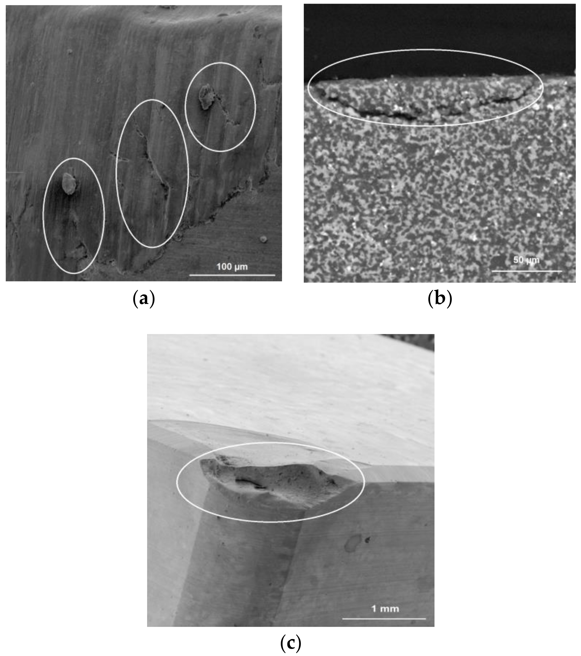
Figure 1 shows the images from a scanning electronic microscope of a classical defect of an insert made of ceramics based on Al2O3, leading to its failure during operation: the initial cracks on the main rear surface (Figure 1a), subsequently leading to the development of a crack (Figure 1b), and the brittle rupture (shearing) of the cutting edge during the process of cutting (Figure 1c).
As for the effectiveness of applying thin-film coatings to ceramics in order to improve the performance, there is no single opinion among scientists and manufacturing companies. Many manufacturers of ceramic tools consider the effects of coating of ceramic inserts to be dubious and unproven [11,12,13].
A quantitative effect from the coatings of ceramics, which is comparable to that which is achieved with the coating of high-speed and carbide tools, is often expected. It is well known that the tool life of high-speed steels and hard alloys is increased by up to eight times compared to tools without coatings, owing to innovative coatings. It is unreasonable to expect a comparable result from the coating of ceramics. Ceramics are a structurally heterogeneous material, and have significantly different physical and mechanical characteristics. Their specific features should be taken into account when designing coating technologies. It is evident that the technological principles used for developing and successfully improving high-speed steel and hard alloy tools should not be applied to ceramics, and the increase in durability cannot be repeated. Practice shows that a two-fold increase in the resistance of ceramics should be considered a perfect result.
Scientists immersed in this problem, including the scientific team of the Moscow State University of Technology STANKIN, developed the theory that the coating allows for the healing of surface defects, creates a barrier in the surface layer of the ceramic base that hinders the generation of operational defects, and forms an obstacle that prevents the exit of internal cracks in the surface (in their presence or origin), as well as limiting underwater energy at the mouth of the cracks [14,15,16].
Unfortunately, the processes of the nucleation (development) of the cracks, leading to the brittle fracture of the ceramic tool, occur rapidly in the process of cutting. The modern instrument base (vibroacoustic and acoustic-emissive sensors) makes it possible to adequately predict and identify the brittle fracturing process by collecting and processing the diagnostic information from the cutting zone [17,18,19]. However, visualization of the cutting zone is practically impossible due to the specific nature of metalworking, and all conclusions made are based mainly on the results of mathematical modeling [20,21,22,23,24].
The purpose of this article is to experimentally study the role of thin-film vacuum-plasma coatings when applied to ceramic inserts based on aluminum oxide, Al2O3 + SiC and Al2O3 + TiC. To achieve this goal, we set upon the task of experimentally evaluating the transformation of important surface characteristics and the surface layer of ceramic inserts that occur during the coating process of diamond-like coating (DLC), TiZrN, and TiCrAlN. In the final part of our research, the quantitative evaluation of the effects of the changes in the surface and surface layer properties on the performance of ceramic inserts during the milling process of hardened bearing steel was studied.
2. Materials and Methods
2.1. Cutting Tools and Material Being Processed
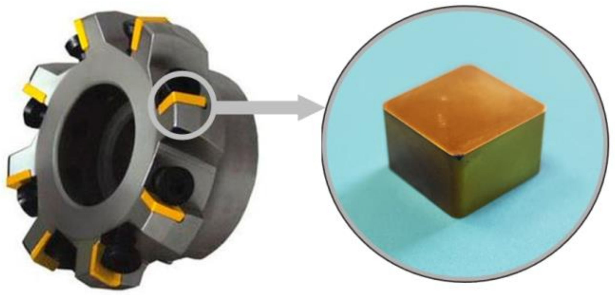
A 125-mm-diameter eight-toothed end mill with a mechanical fastening of ceramic inserts was used as a cutting tool during the experiments (Figure 2). Hardened steel 102Cr6 with a hardness of 60–62 HRC was used as the material.
Square inserts of 12 mm × 12 mm × 4.76 mm made from oxide ceramics strengthened with silicon carbides were used for the conducted experiments. This kind of ceramic has a composite structure which was achieved by adding ceramic powdered SiC to the main powdered Al2O3 in the form of whiskers [25,26,27,28,29,30,31,32]. The whiskers provide higher strength characteristics during sintering. Samples of the same shape and dimensions made from the most common ceramics, Al2O3 + TiC, were used to complementarily refine and confirm the obtained results [33,34,35]. CC650 and CC670 ceramic inserts produced by Sandvik Coromant (Stockholm, Sweden) were used during the experiments.
2.2. Deposition of Vacuum-Plasma Coatings on Ceramics and Coating Compositions
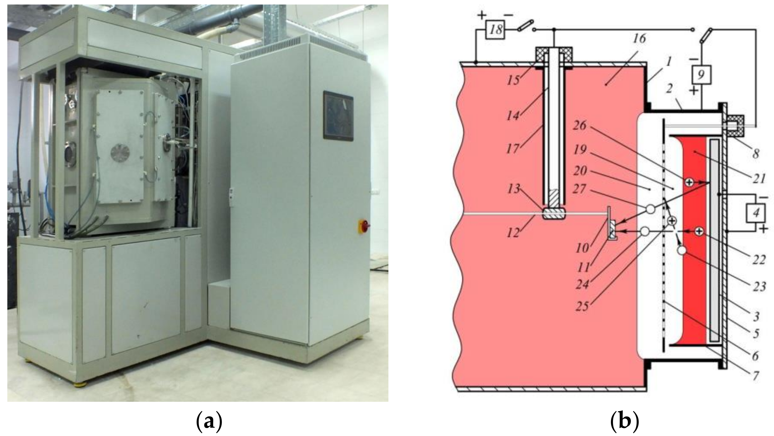
A unique technological vacuum-plasma plant, developed by the scientific group of scientists of Moscow State University of Technology STANKIN (Moscow, Russia), was used for the deposition of coatings onto ceramic inserts based on aluminum oxide, Al2O3 + SiC and Al2O3 + TiC. The construction of the plant ensures bombardment of the synthesized coatings using high-energy particles as fast atoms and gas molecules (Figure 3).
Because ceramics have low electrical conductivity, the application of traditional technological principles to them and the supply of negative voltage to them are less effective than with conductive materials (e.g., high-speed steels and hard alloys). Furthermore, the spraying of the surface of ceramics during cleaning is less intense, and when the coating is condensed due to insufficient surface activation, low-density coatings and low adhesion strength are often the result. It is essential to ensure continuity of the bombardment of the coating on the entire surface of the product during the synthesis of high-quality coatings. For this, the trajectories of the deposited atoms and the bombarded synthesized coating of fast molecules must coincide [40,41]. Otherwise, metal atoms and fast molecules will affect separate parts of the surface in turn, resulting in the deposition of coatings without the bombardment with fast particles alternating with the bombardment with fast particles without deposition of the coating. Thus, the conditions for obtaining the essential properties of the coatings will not be created. A complete coincidence of the trajectories was achieved as a result of the fact that both sources were combined in the same device with the emission surface common to the particles. As seen in Figure 3, the high-energy gas atoms (24) obtained by a charge exchange of ions (22) accelerated by high-voltage pulses applied to the grid (6) bombarded and synthesized on the ceramic substrate (11) from the atoms (27) of the sputtered target (3) and the nitride coating. The material of the target (3) can be changed depending on the composition of the applied coatings. The bombardment by high-energy gas atoms in the process of the coating deposition ensures the formation of high-quality coatings with grain sizes less than 100 nm. The choice of composition of the wear-resistant coatings for the cutting inserts made of ceramics is not a trivial task. It is necessary to choose or develop a coating composition that will create a compatible and practically useful system in combination with the main ceramic material. The following three systems were chosen as wear-resistant coatings for the ceramic inserts made from aluminum oxide of two systems, Al2O3 + SiC and Al2O3 + TiC, based on the results of previous works [42,43] and an in-depth analysis of the operating conditions of ceramics during the milling of hardened steels.
A diamond-like coating (DLC) was obtained by sputtering a graphite target in a glow discharge plasma, resulting in an amorphous coating structure consisting of carbon atoms with both diamond- and graphite-like bonds [44,45]. This coating is traditionally characterized by a low friction coefficient and has noticeably higher microhardness values in comparison to tool ceramics.
TiZrN coating is characterized by a relatively high microhardness, with a change in the coefficient of linear expansion close to the ceramic under heating, which is essential when resisting thermal loads arising in the cutting zone [46,47]. Moreover, it is possible to predict a sufficiently high thermodynamic stability and resistance to the propagation of cracks during operation caused by the high binding energy in the crystal lattice of this coating. TiCrAlN coating has a microhardness comparable to the hardness of the ceramic substrate, which eliminates the formation of stress at the interface due to the difference in properties; however, it is characterized by good elasticity and high resistance to the adhesion processes [48,49].
It is critical to select the optimum holding time in the vacuum chamber for deposition of the coatings, on which the thickness of the formed coating depends. Films which are too thick (over 6 μm) can significantly increase the number of defects in the coating, can reduce the adhesion bond strength of the coating to the ceramic substrate, and can reduce the ability of the coating to resist elastoplastic deformation. Excessively thin films (1 μm or less) will not have a noticeable effect on the operational properties of the ceramic inserts, because they will not be able to resist the adhesion processes and will not be a barrier preventing the development of cracks and their emergence on the surface. The preliminary experiments made it possible to find the rational thicknesses of the coatings for the current investigation under conditions of interrupted cutting for the diamond-like coating of 2 μm, and for the TiZrN and TiCrAlN coatings of 3.5 μm. The thickness of the coatings was directly dependent on the holding time of the ceramic inserts. The thickness was determined on a witness sample, which was placed in the vacuum chamber of the experimental plant along with the ceramic inserts. The control and quantitative evaluation were carried out using the standard method on an industrial coating thickness tester, CALOTEST, equipped with an optical measuring system.
After deposition of the coatings according to the described technology, their microhardness values were determined as follows: DLC coating—36 GPa, TiZrN coating—28 GPa, TiCrAlN coating—24 GPa.
2.3. Surface Topography and Microgeometry of Ceramic Cutting Inserts
A high-precision profilometer, Hommel Tester T8000 (JENOPTIK Industrial Metrology, Jena, Germany), was used to assess the roughness of the working surfaces of the ceramic inserts before and after coating. An additional analysis of the working surfaces of the ceramic inserts was carried out using a scanning electron microscope (SEM), Tescan VEGA3 LMH (Brno, Czech Republic).
The rounding radius of the cutting edges of the ceramic inserts was determined and measured using a certified high-precision three-dimensional (3D) microscope, MicroCAD Premium+ (GFMesstechnik GmbH, Teltow, Germany), with an error of ±1 μm. A color-imitating 3D model and a profilogram of the radius of the cutting edge were drawn based on the light-section method for each sample.
2.4. Strength Characteristics of Ceramic Cutting Inserts
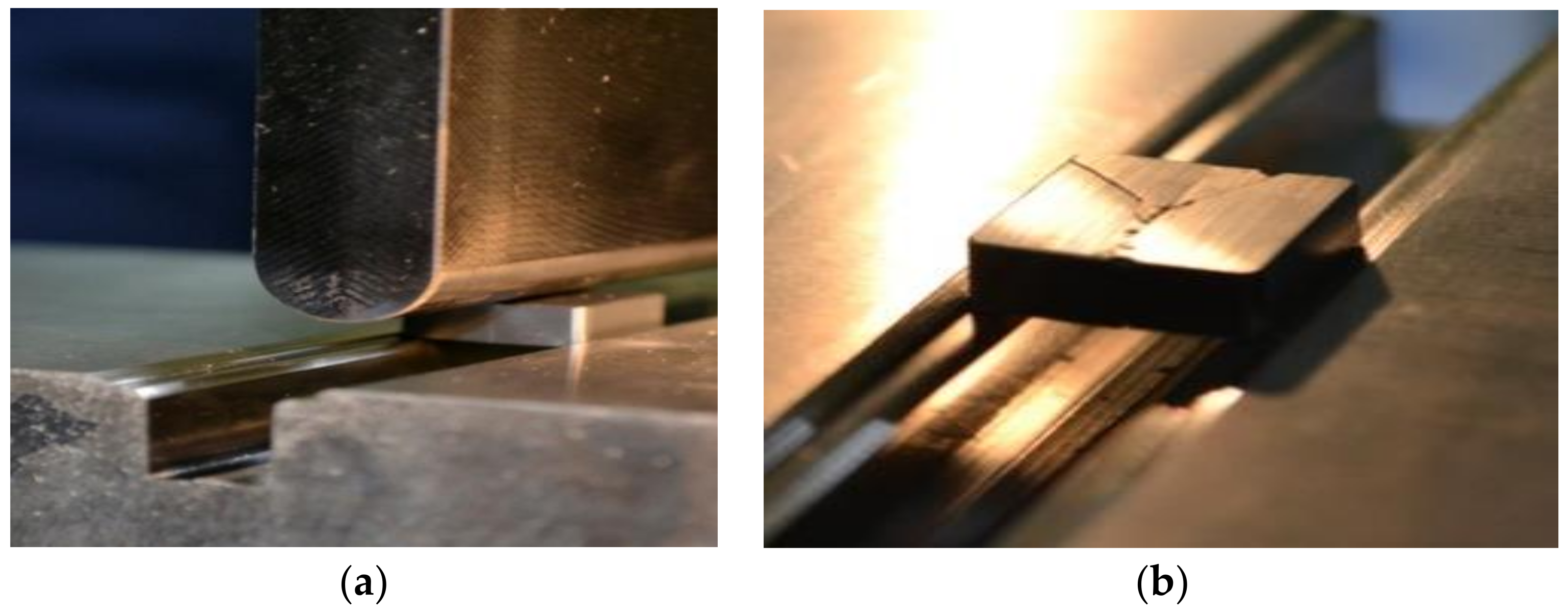
Traditionally, the bending strength tests of coated samples are carried out using three- or four-point bending methods, for which particular control samples (bunches) of a specific geometric shape are made. In the frames of this article, the idea was to maximally approximate the control samples to the configuration of the real cutting ceramic inserts. It was necessary to evaluate the effect of coating directly on the strength of the ceramic cutting insert. The rigging and experimental protocol were developed for the current research (Figure 4a,b). The device presented as a massive parallelepiped with a groove and ledge, on which a square ceramic insert with a size of 12 mm × 12 mm × 4.76 mm was installed with a small gap. During the course of the experiment, a force was applied to the punch rigidly attached to a universal test machine, INSTRON (Norwood, MA, USA), until the insert was destroyed. A critical requirement in the construction of the rigging was to ensure a strict application of the punch force to the sample. The diagrams of the force and the punch displacement along the Fz axis, and the critical force at which destruction occurred were recorded.
2.5. Adhesive Bonding of Coatings and Surface Layers of Ceramic Inserts
A micro-scratch tester, MST CSEM (CSEM Instruments, Neuchâtel, Switzerland), was used to assess the strength of adhesive bonding of the coatings with the ceramic substrates, involving scribing by a diamond pyramid with a variable load from 1 to 40 N, while recording the acoustic emission signal spectrum. The scribing was implemented by an indenter in the form of a diamond cone with an angle at the apex of 120° and a tip radius of 100 μm. The coated ceramic samples traveled at a constant speed, and the recording and decoding of the acoustic emission signals were carried out using the developed software.
In order to analyze the adhesion of the coatings to the ceramic substrates further, auxiliary studies were carried out. This consisted of studying the shape and dimensions of the crater due to the abrasive wear of the coatings, which was formed by the targeted impact on the surface of the ceramic inserts using abrasive particles of the Al2O3 ceramic. They were moved with air flow at a pressure of 1 bar (the effect of air-abrasive flow); the time of exposure to the surface of the experimental samples was 5 s.
2.6. Friction Coefficient of Ceramic Inserts
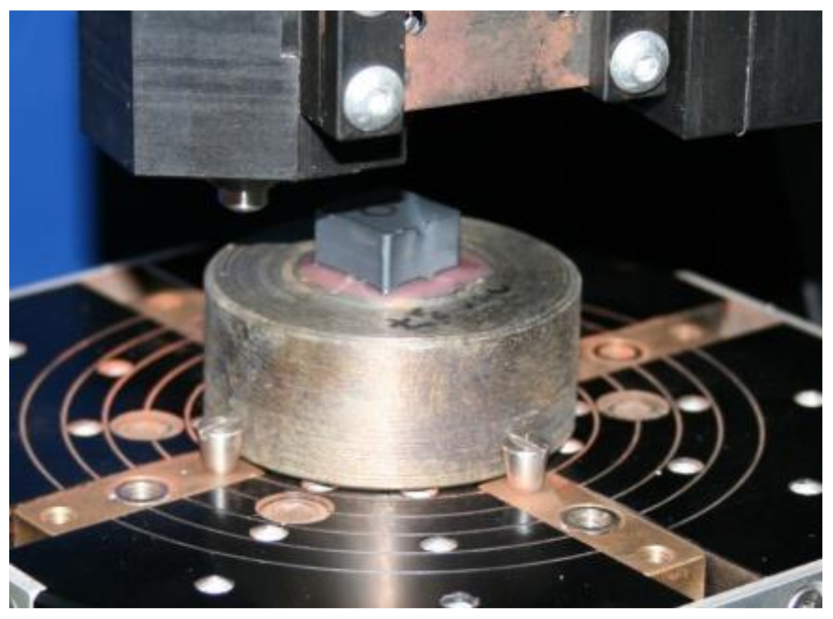
The friction coefficient was measured on a test machine, Tetra Basalt N2 Precision Tribometer (Falex Tribology NV, Rotselaar, Belgium), to evaluate the frictional properties of the ceramic samples with the coatings. During the tests, the coefficient of sliding friction of the friction pair of the ceramic insert and the counter body made of hardened steel 102Cr6 (Figure 5) was determined. The tests of all samples were carried out under conditions of dry friction at identical normal loads on the counter body (1 N), with the speed of relative displacement being 2 mm·s−1, and the friction path being 90 mm.
Since, during the cutting process, the tool with the workpiece undergoes increased thermal loads, it was critical to measure the friction coefficient not only at room temperature, but also under heating conditions of the samples. An infrared heater and temperature sensors were used for forced heating of the samples to a temperature of 500 °C.
2.7. Operational Testing of Ceramic Cutting Inserts
The wear studies and operational tests of the original cutting inserts (without coatings) and the ceramic inserts with the various coatings were carried out during face milling on a milling machine, Willemin-Macodel 528S (Willemin-Macodel SA, Delemont, Switzerland). The cutting conditions were as follows: cutting speed (V) = 380 m/min, feed (S) = 0.1 mm/tooth, and depth (t) = 1 mm. The cutting inserts of the ceramics with a special clamp were fixed in the cutter body as shown in Figure 2, which ensured the following tool geometry: primary (front) clearance angle (α) = 10°, and back rake angle (γ) = −7°. The blank being processed was made of hardened steel 102Cr6 in the form of a parallelepiped with the following dimensions: l = 800 mm, b = 85 mm, h = 85 mm.
The failure criterion of the ceramic insert during the experiments was the wear of the rear surface hr, the limiting value of which was 0.45 mm. As seen during the preliminary experiments, the tool maintained its operative state until the moment the specified value was reached. Exceeding this value increased the number of chips at the cutting edge (sudden failures) several times, which can lead to the formation of defects on the workpiece. Every three minutes during the operation, the quantitative value of the insert wear along the back surface was monitored. The values were recorded for subsequent processing. Each experiment was repeated at least five times to avoid errors.
3. Results
3.1. Surface Topography and Microgeometry
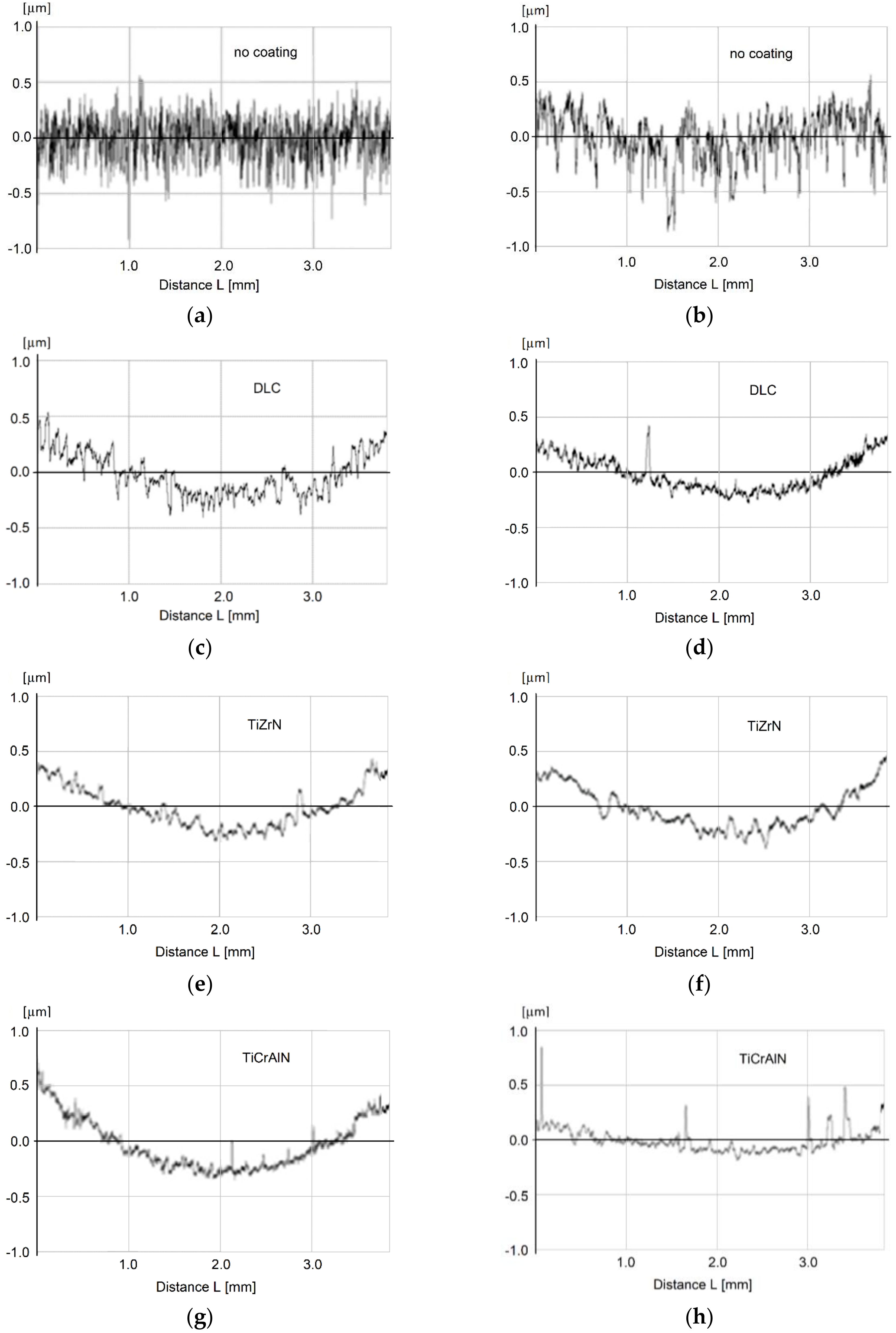
The obtained results show that the deposition of coatings onto the surfaces of ceramic inserts changed their relief considerably, and it had a significant effect on the size and shape of the microroughness formed during the final diamond grinding of the cutting inserts. Figure 6 shows the profilograms taken from the front surface of the samples of the Al2O3 + TiC and Al2O3 + SiC ceramics before and after deposition of the diamond-like coating. It is important to emphasize that the profilograms did not differ after coating with the two other compositions. It can be seen that, after the deposition of the coatings, the height of the microroughness decreased, and the regular microrelief of the surface changed markedly.
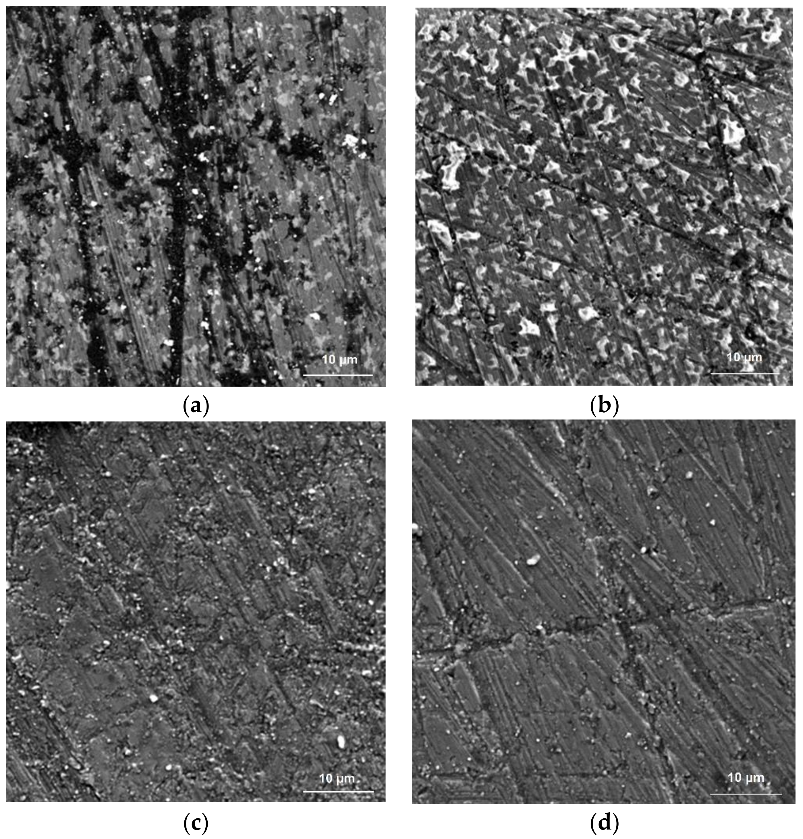
The noted effects are illustrated by the images of the working surfaces of the ceramics before and after deposition of the diamond-like coating, obtained using a scanning electronic microscope (Figure 7). It can be seen that the two types of ceramic inserts before the deposition of the coating had pronounced grinding scratches, which are typical for tool ceramics (Figure 7a,b). They are known as stress concentrators as they increase the roughness and the frictional force between the falling chips and the front surface of the cutting insert. At the same time, a large number of craters from the grains, which were torn out from the sample during grinding, were also detected on the sample of Al2O3 + TiC. The SEM images of the surface obtained on the samples with the diamond-like coating show the significant changes (Figure 7c,d). The surface became more homogeneous; no deep craters were observed; the scratches after grinding were still visible, but not as pronounced and profound as before; the cavities from torn grains were practically absent.
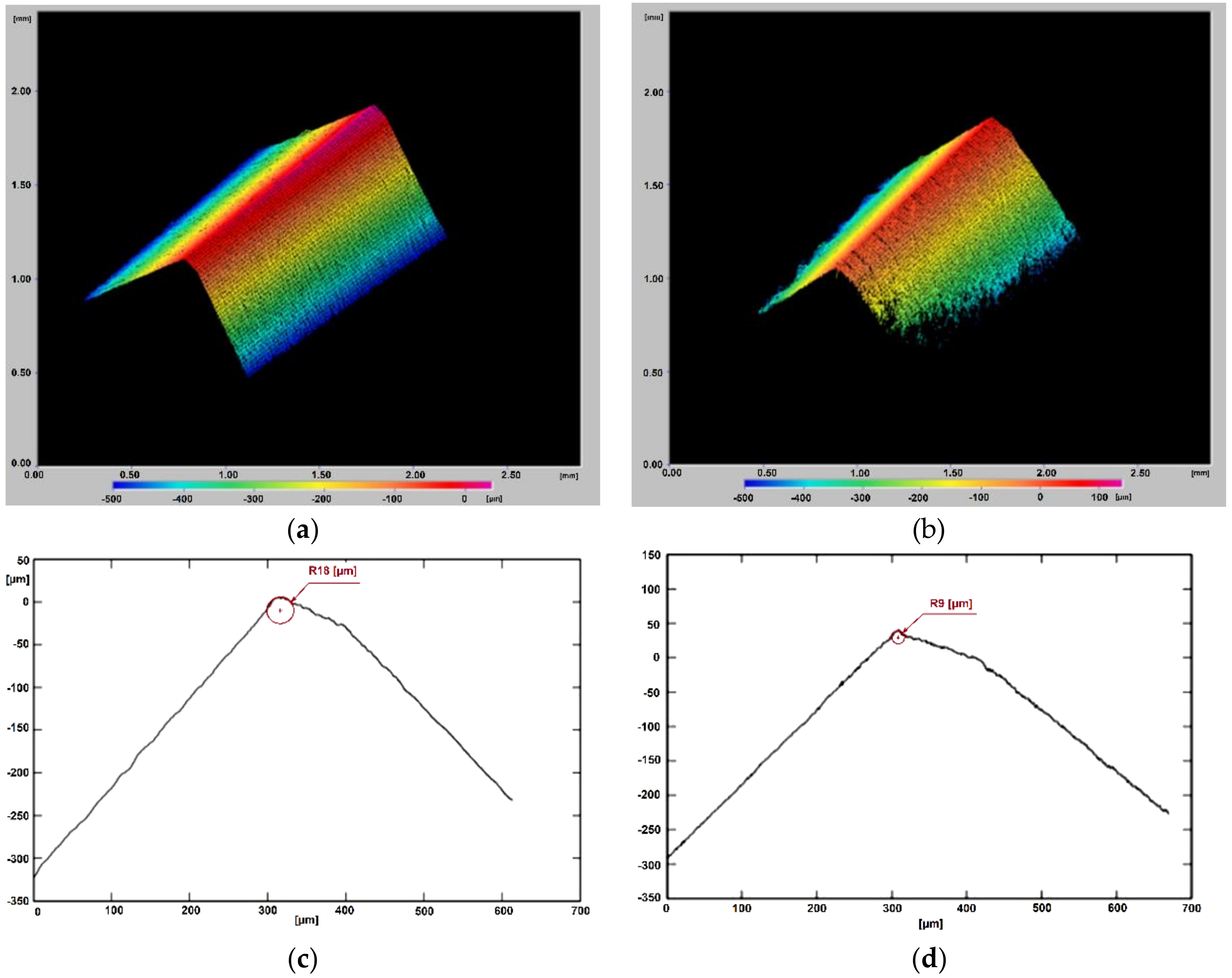
It was found that the application of coatings transformed the geometry of the ceramic cutting inserts. The radius of curvature of the cutting edges (R) decreased. Before the coating of the Al2O3 + TiC ceramic inserts, the radius (R) corresponded to a value within the range of 18–24 μm. For the Al2O3 + SiC ceramic inserts, the radius (R) was within the range of 15–19 μm. After coating, the radii decreased to the range of 10–13 and 7–10 μm, respectively. Figure 8 shows the obtained results for the sample of the Al2O3 + SiC ceramic with the diamond-like coating. It is important to emphasize that the results described above are valid not only for the ceramic samples with diamond-like coatings, but also for the two other investigated coatings, TiZrN and TiCrAlN.
3.2. Strength Characteristics
Figure 9 presents the experimentally obtained relationships of the applied load and the displacement of the punch along the Fz axis before the actual destruction of the ceramic inserts with the different coatings. The force–displacement diagram was recorded during the experiment. The graphs show the averaged straight lines approximating the obtained results. The drawing of each dependence (in the form of a straight line) was carried out based on testing four samples for each type of ceramic insert.
The obtained results show that the ceramic inserts after the application of the coatings demonstrated higher values in terms of the forces needed to break the samples, indirectly indicating their higher strength characteristics. In particular, the average destructive (critical) force corresponded to 5.3 kN for the samples of Al2O3 + TiC ceramic before the deposition of coatings. After coating, the average destructive (critical) force ranged from 6.2 to 7 kN, i.e., an increase in the range of 16%–32% was observed. Similar dynamics were revealed for the cutting inserts of the Al2O3 + SiC ceramic. If the breakdown of the samples occurred at 6.2 kN before deposition of the coatings, then, after coating, the average destructive (critical) force was in the range of 7.2–7.5 kN, which corresponds to a gain of 16%–20%. In this case, an increase in the displacement of the punch at which destruction occurred for the samples with coatings was detected.
3.3. Adhesive Bond of Coatings
Fragments of the results of the scratch test are shown in Figure 10. The given images refer to the samples of Al2O3 + SiC ceramic at loads on the indenter from 1 to 40 N. Analysis of the macro photographs of the tracks of the indenter displacement on the surface of the ceramic samples with the different coatings demonstrates the adequate strength of the adhesive bond with the ceramics for each type of studied coating. Even at the maximum values of the load on the indenter (on the order of 40 N), peeling of the coatings was not observed. Additionally, the acoustic emission sensors did not detect any sharp peaks, which traditionally indicate the separation of the coating from the ceramic substrate and the fixation of the value of the critical (destructive) load. Precisely the same picture was observed in the study of the samples of Al2O3 + TiC ceramic with the various coatings. The performed scratch test demonstrates a qualitative picture, but does not provide an opportunity to compare the different coatings quantitatively.
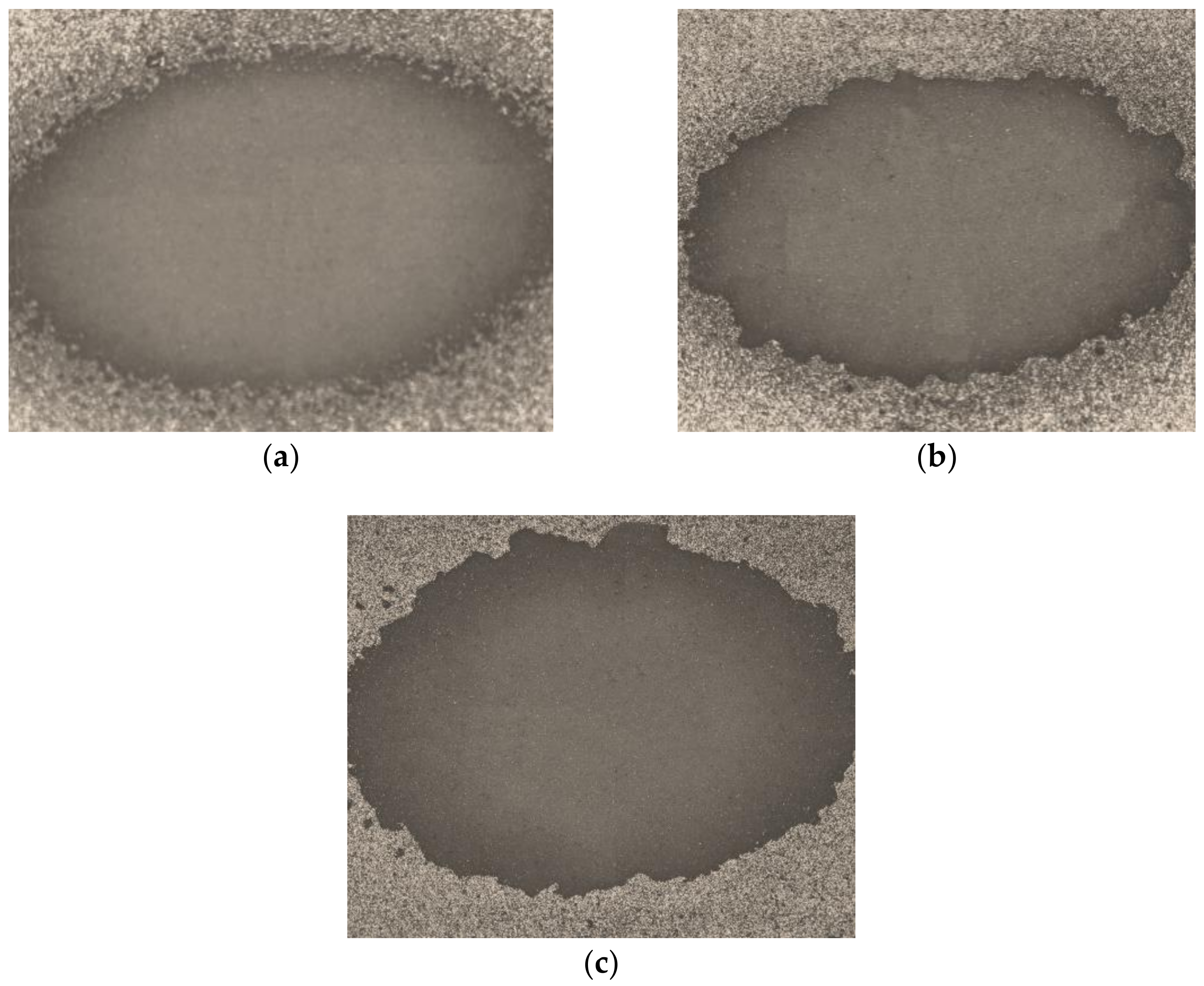
Therefore, additional experiments were subsequently carried out to determine the effect of air-abrasive flow on the surface of the ceramic inserts with various coatings. A comparative evaluation of the strength of their adhesion bond with the substrate shows more pronounced differences (Figure 11). The presented results demonstrate that the most significant hole and area were formed on the samples of Al2O3 + TiC ceramic coated with TiCrAlN. A similar result concerning the size of holes was observed for the samples with the diamond-like coating and the TiZrN coating. The principal difference lies in the fact that the hole boundaries on the sample coated with TiZrN had a more precise contour in the shape of an ellipse, while the hole on the sample with the diamond-like coating had “torn” edges. Similar results were obtained for the samples of Al2O3 + SiC ceramic.
3.4. Friction coefficient
Figure 12 shows the results of the measurements of the coefficient of sliding friction of the Al2O3 + TiC ceramic inserts with various coatings on the counter body of hardened steel 102Cr6 under dry friction conditions at room temperature (left-side graphs) and at a temperature of 500 °C (right-side graphs). Each experiment was carried out between three and nine times to minimize errors in measurement and errors in the interpretation of the results. Families of curves, which characterize the coefficient of friction of the surface of the samples with the coatings from a distance (friction path) were drawn. It can be seen that the results of the friction tests obtained at room temperature and under heating conditions were very different. In particular, all samples except the ceramic inserts with the TiCrAlN coating showed reasonably stable results. A slightly smaller coefficient of friction than for the other samples was observed for the sample with the diamond-like coating (in the range of 0.11–0.18), which was predicted and correlated with available data from the literature.
The tribological studies, which were carried out under heating conditions, showed that the uncoated ceramic samples behaved extremely unstably. The coefficient of friction firstly increased, then reached a maximum value (on the order of 1.2), before sharply decreasing to 0.12, and then increasing once more. The samples with coatings showed reasonably stable results in comparison to the uncoated ceramic samples. There were no sharp jumps and differences in the graphs. Even the TiCrAlN coating, which exhibited instability at room temperature, showed satisfactory results under heating conditions. The ceramic samples with the diamond-like coating and the TiZrN coating demonstrated the minimum values of the coefficient of friction under heating conditions (in the range of 0.12–0.49). The coefficient of friction of the samples with the TiCrAlN coating was in the range of 0.12–0.65.
3.5. Operational Testing
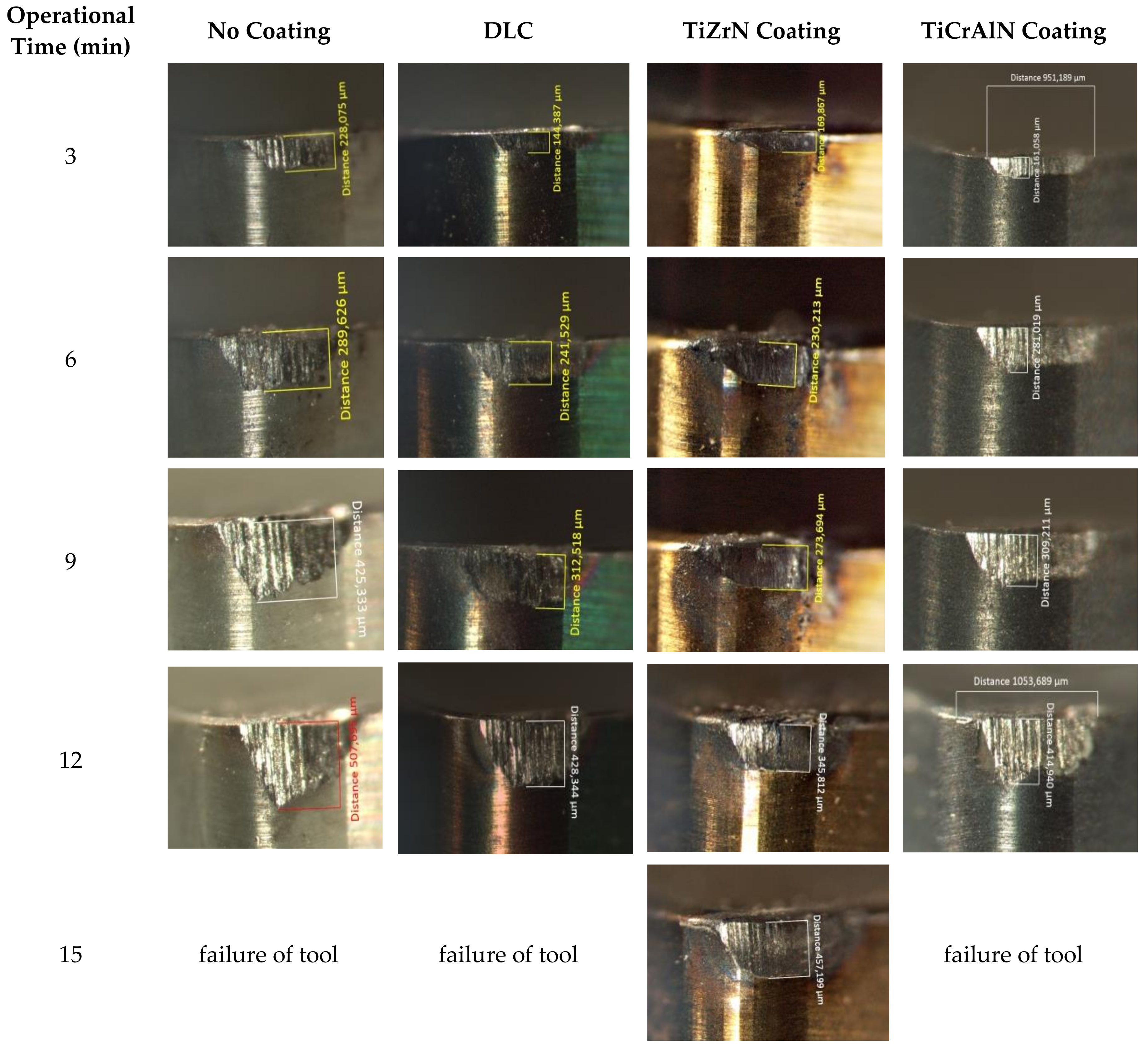
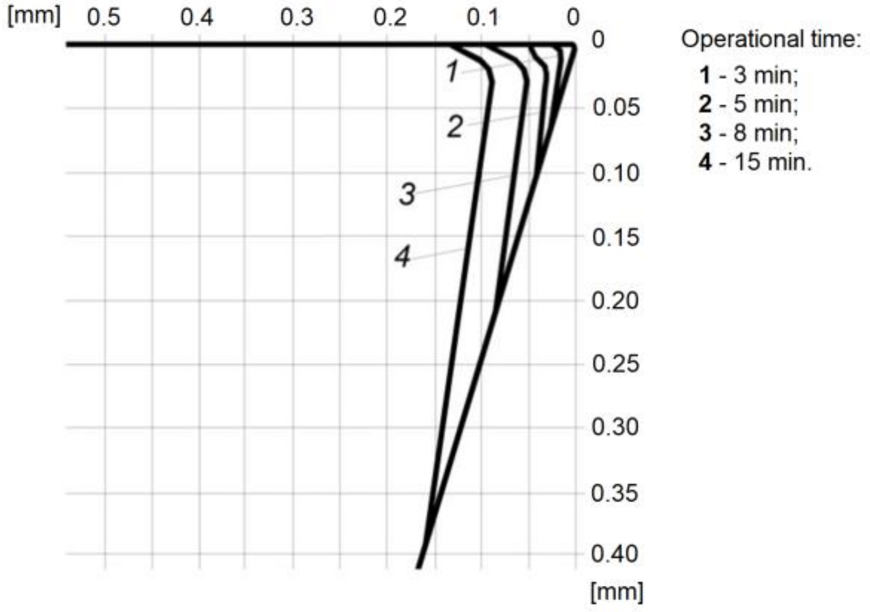
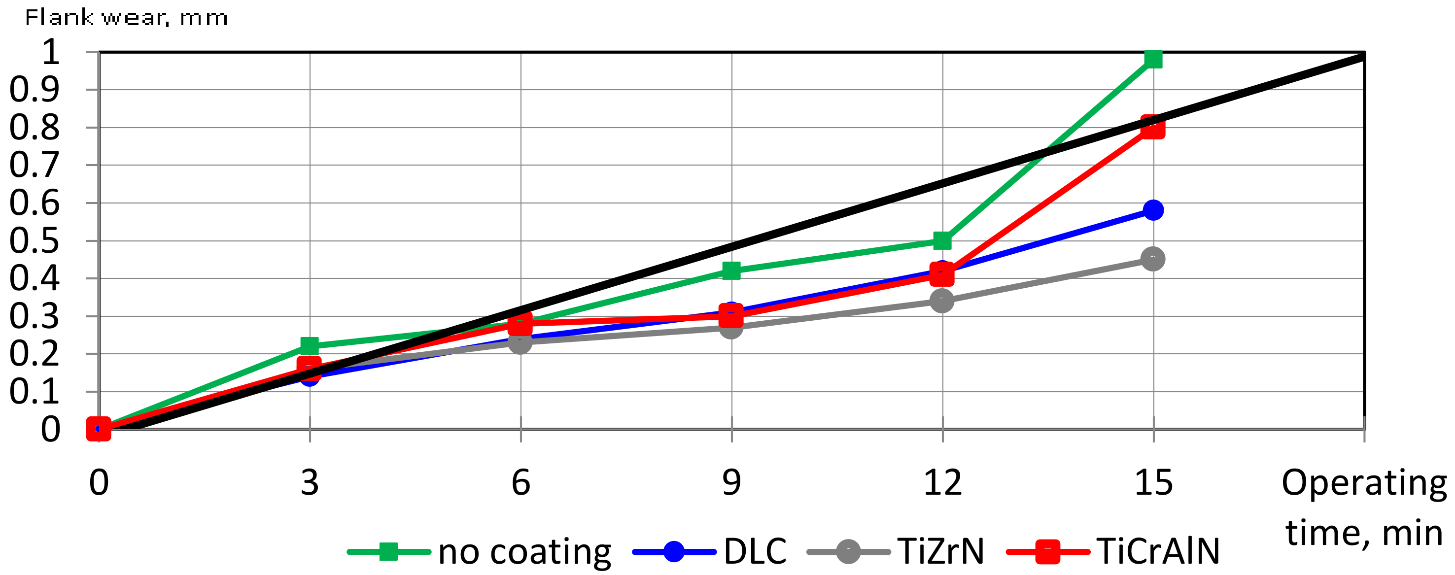
Figure 13 shows the characteristic depictions of the wear of the cutting part of the inserts of the Al2O3 + SiC ceramic with various coatings during the milling of hardened steel 102Cr6 with a cutting speed of V = 380 m·min−1, a feed of S = 0.1 mm/tooth, and a depth of t = 1 mm. It can be seen that the coating on the ceramics did not change the mechanism and nature of wear. The principal foci of wear developed on the rear surface of all samples. However, the development of the chamfer of wear on the rear surface was more intensive for the ceramic inserts without coating, in contrast to the inserts with coatings, which led to rapid and catastrophic wear. It should be noted that not all the coatings, which were considered in the current study, help slow the onset of catastrophic wear. For example, the TiCrAlN coating did not make a tangible contribution to an increase in the durability of the ceramic inserts. The described regularities were also noted in the study of the wear of the inserts of the Al2O3 + TiC ceramic. Figure 14 shows the profilograms of the wear development on the working surfaces of the ceramic insert with the diamond-like coating (DLC). The development of the tool wear can be seen over the course of the operation. The presented evolution of the wear helps in the understanding of the mechanism of the thin-coating operation. The main contribution to the decrease in the wear rate of the coated insert was made by the so-called “edge effect”, as described below. In the first minutes of the operation, as seen in the profilograms of its working surface, the coating rubs through its entire thickness in the areas near the cutting edge. However, the further growth of wear spots along the working surfaces of the insert is restrained by the edges of the contact areas, which preserve the improved characteristics achieved by the coating. The results of the comparative quantitative evaluation of the wear rate of the inserts of Al2O3 + SiC ceramic, depending on the presence of the coating and its composition, for the end milling of hardened steel 102Cr6 are shown in Figure 15. It can be seen that the operational times to the failure of the tool (a wear limit of 0.45 mm) were as follows:
- 10 min for the uncoated inserts;
- 13 min for the inserts coated with the DLC;
- 12 min for the inserts coated with TiCrAlN;
- 15 min for the inserts coated with TiZrN.
This regularity was preserved throughout the range of cutting conditions in the study of the milling of hardened steel 102Cr6. The resistance to failure of the Al2O3 + TiC and Al2O3 + SiC ceramic inserts with the TiZrN coating was 1.4–1.8 times higher than that with the uncoated inserts, while with the DLC, it was 1.2–1.5 times, higher, and with the TiCrAlN coating, the effect was the least significant, being 1.1–1.3 times higher.
4. Discussion
The obtained results demonstrate the important influence of the coatings on the properties of the surface and the surface layer of ceramics, as well as their strength characteristics and the microgeometry of the tool. An increase in the operational characteristics of the ceramic inserts during the milling process was observed as a consequence.
It is essential to understand that the smoothing and reduction of the surface micro-reflection level and the decrease in the surface defects of the ceramic inserts, which were observed in the profilograms and SEM images of the samples after deposition of the coatings (Figure 6 and Figure 7), are critical. The practice shows that even the most modern abrasive technologies cannot exclude the formation of certain defects on the surface of the ceramics, such as grain breaks, grinding scratches, burns, and residual abrasive in the cavities of microroughness. All these defects are the stress concentrators and the foci for the formation and development of the cracks in the structurally heterogeneous ceramic material, which creates excellent conditions for the subsequent crumbling or chipping of the working surfaces of the tool during operation.
Thus, it can be confirmed that the deposition of the coating contributes to the reduction of the surface defects, which are traditionally formed in the surface layer of the ceramics during its manufacturing. It is essential to understand the coating with 2–3 μm of thickness does not smooth the microroughness itself, but reproduces or copies the relief of the surface of the sample. The reduction in the height of microroughness and the noticeable change in the regular microrelief occur during the deposition of coatings in the vacuum chamber of the operational unit (Figure 3). The removal of submicron layers occurs during the stage of surface cleaning and activation when the high-energy gas atoms (24) bombard the surface of the ceramic samples (11).
The transformation of the microgeometry of the cutting inserts described above, namely the significant reduction in the radius of the rounding of the cutting edge (R, essentially the tool sharpening), is also a consequence of the bombarding high-energy gas atoms provided by the coating technology developed in the study (Figure 8). It is an original effect which was observed during deposition of the coating on the ceramic tool, since most coatings increased the radius of the rounding of the cutting edge. A similar phenomenon was observed and described in detail in [50], where a beam of high-energy gas atoms sharpened the knife blade made of dielectric ceramics based on zirconium dioxide. In that work, the radius of the cutting edge of the knife decreased from 5 to 1 μm, and its value directly depended on the distance between the axis of the beam of gas atoms and the cutting edge of the blade.
This geometric parameter has a simultaneously important and ambiguous influence on the cutting ability of the tool. On the one hand, the increase in R helps increase the strength of the cutting edge of the tool, which is a positive result. Mainly, this is correct in the case when machining with a ceramic tool is implemented under conditions of increased heat load. On the other hand, the increase in R limits the minimum possible depth of material cutting in the case of finishing and super-machining. If the radius (R) is too large and the cutting depths are small, the cutting edge will not cut, but the surface layer of the workpiece will be kneaded. Thus, the described feature of the proposed technology and its effect on the radius (R) must be taken into account when designing and applying a coating onto ceramic inserts.
Attention should be paid to the results of the strength tests of the ceramic inserts after deposition of the coatings, which show an increase in the values of destructive forces of up to 32% (Figure 9). There is no doubt that it is a consequence of the already discussed decrease in the height of surface microroughness and the reduction in the number of surface defects of the ceramic inserts, which are the stress concentrators and the foci for crack development. Thus, the bulk properties of the ceramic, its strength characteristics, can be transformed by acting on the surface layer of the ceramic during the coating process. Here, it is necessary to emphasize that the influence of applying coatings using the advanced technology occurs exclusively on the surface layer and does not affect the product volume (the temperature in the vacuum chamber was on the order of 600 °C; this temperature is not significant for heat-resistant ceramics). Moreover, heating to higher temperatures occurs in the near-surface layers of the samples due to high-energy atoms.
The obtained results for the evaluation of the strength of adhesion bonding of the coatings with the ceramic inserts demonstrate a satisfactory outcome. Delamination of the coatings after application of the load was not observed for all test samples (Figure 10). This indicates that the surface of the ceramic samples was well purified and activated by high-energy atoms in the process of coating.
A comparison of the wear craters formed on the coated samples during the targeted action of the air-abrasive flow showed that the largest delamination area was formed on the samples with the TiCrAlN coating (Figure 11).
The results of investigating the friction coefficient of the three different coatings showed that the TiCrAlN coating was the least stable both at room temperature and under heating conditions. The results obtained correlated with the results of the subsequent experiments. It was the TiCrAlN coating that showed the least wear resistance of the three coatings studied, conforming with the natural laws.
It should dwell on the results of experiments comparing the friction coefficients of the ceramic samples with the coatings and the original samples without coating under heating conditions (Figure 12). It is well known that the temperature in the processing zone during cutting and the temperature of the heating of the samples are significantly higher than that during the tribological tests. Today, it is practically impossible to reproduce the real loads that the tool experiences during the cutting process, and to obtain informative results on the values of friction coefficients of the samples at the same time. Nevertheless, the results obtained under heating conditions for the ceramic inserts (500 °C) show rather interesting experimental trends, and can be used as a basis for further research.
The results showed the extreme instability of uncoated samples. The coefficient of friction varied substantially within the range of 0.12–1.2. The effect of the high heat resistance of ceramics used in the cutting tools can be explained as follows, and it is related to the behavior of the counter body material from hardened steel 102Cr6 under heating conditions. Presumably, oxidants are formed under heating conditions in the presence of oxygen on the surface of the counter body under their physicochemical properties, which differ from those of the underlying material. Thus, an intermediate solid layer is formed between the ceramic insert and the counter body under heating conditions, which changes the resistance of deformation of the surface layer of the counter body. Firstly, the coefficient of friction grows with the rise in temperature, before reaching a maximum value, and subsequently decreasing. This pattern repeats cyclically. Presumably, the characteristics of the dependence can be explained by the following facts:
Firstly, the coefficient of friction grows due to the oxidation of the surface and the formation of solid metal oxides that impede the deformation of the counter body;
Next, the oxide film softens with the further rise in temperature, and it begins to play the role of a lubricant, reducing the coefficient of friction.
The coating deposed onto the cutting insert essentially acts as a solid lubricant, which acts as an intermediate layer between the counter body and the ceramic tool that entirely or partially isolates them from each other. This explains the more stable behavior of coated ceramic inserts in comparison with the uncoated samples during the tribological tests under heating conditions, and it allows understanding the nature of the changes occurring in the coefficient of friction. Here, it is necessary to take into account the surface changes that occur during the application of coatings in the microrelief. The dependence of the coefficient of friction on the roughness of a surface is quite complex and ambiguous, but there is an effect of its decrease.
The phenomena occurring during the tribological tests proceed identically during the interaction between the tool and the workpiece during the cutting process; they influence the results of the operational tests as well (Figure 13, Figure 14 and Figure 15).
It was found that the coatings effectively reduced the wear rate of the Al2O3 + TiC and Al2O3 + SiC ceramic inserts across a wide range of cutting conditions during the milling of hardened steel 102Cr6. The maximum effect was achieved with the TiZrN coating. The time to failure (operational durability) increased 1.8-fold in comparison with the uncoated inserts. The effect of depositing diamond-like coatings was less significant. The operational durability increased 1.5-fold in comparison with the uncoated inserts. The achieved increase in operational durability was a direct consequence of the changes in the properties of the surface and the surface layer of the ceramic described above, as well as the improvement of the strength characteristics.
The TiCrAlN coating of the ceramic inserts proved to be the least effective during the milling of hardened steel 102Cr6, which correlates with the results of the previous experiments. It also showed results inferior to that of the TiZrN coating and the diamond-like coating in evaluating the strength of adhesion bonding, and during the tribological tests. Perhaps this is caused by the affinity of the material of the TiCrAlN coating and the material of the workpiece, as well as their mutual diffusion of chromium at high temperatures that occur during the cutting process. It does not mean that the TiCrAlN coating cannot be recommended for coating ceramic tools; it means that the optimal conditions for its application will be different from those presented in the article. This could also be the subject of separate studies.
In conclusion, it should be mentioned that the choice of coating composition for the ceramic cutting inserts is an extraordinarily complex and ambiguous task. A coating can be effective for some cutting conditions, and can turn out to be utterly useless for others. It is necessary to choose or develop the coating composition that will create a compatible and efficient system in combination with the main ceramic material for each type of cutting process (e.g., turning, milling) and processing conditions (e.g., finishing, semi-finished) for each specific pair of tool and material to be processed.
5. Conclusions
The research carried out and the results show how much the application of coatings transforms the properties of the surface and the surface layer of the ceramic, as well as affecting the strength characteristics and microgeometry of the tool, and the operational stability as a consequence. The main role of coatings on ceramic inserts should be attributed to the following factors:
- The coatings smooth the microroughness of the surface and reduce the number of surface defects, which are traditionally formed during the abrasive processing of ceramics (e.g., diamond grinding and sharpening). At the same time, this effect does not depend on the composition of the applied coating. It is a technological feature of the coating process, which purifies and activates the surface of the ceramic inserts using high-energy gas atoms. Furthermore, the impact of these particles on the cutting edge of the insert ensures its sharpening and reduces the radius of the rounding of the cutting edges. The authors of the article developed the described method. The coatings also contribute to the increase in the strength characteristics of the ceramic inserts caused by the reduction in the number of stress concentrators on the surface and the potential foci of crack development.
- The coating acts as a solid lubricant between the intermediate layer of the material being processed and the ceramic tool, which isolates them from each other. It changes the friction conditions significantly, and ensures more stable operating conditions of the ceramic inserts with coating compared to the uncoated cutting inserts during machining accompanied by the effects of increased temperature.
- The TiZrN coating and diamond-like coating can be recommended as effective means of increasing the operational durability of the Al2O3 + TiC and Al2O3 + SiC ceramic inserts during face milling of high-strength bearing steel across a wide range of cutting conditions.
Author Contributions
Conceptualization, M.V. and S.G.; Methodology, A.M.; Software, A.S.; Validation, M.V., S.G., and A.M.; Formal analysis, A.S.; Investigation, M.V.; Resources, A.M.; Data Curation, A.S.; Writing—Original Draft Preparation, M.V.; Writing—Review & Editing, S.G.; Visualization, A.S.; Supervision, S.G.; Project Administration, A.M.; Funding Acquisition, A.M.
Funding
This research was funded by the Ministry of Education and Science of the Russian Federation (No. 9.7889.2017/8.9).
Acknowledgments
The research was done at the Laboratory of Coatings Deposition of the Department of High-efficiency Machining Technologies of MSTU Stankin.
Conflicts of Interest
The authors declare no conflict of interest.
References
- Koepf, A.; Keckes, J.; Todt, J.; Pitonak, R.; Weissenbacher, R. Nanostructured coatings for tooling applications. Int. J. Refract. Met. Hard Mater. 2017, 62, 219–224. [Google Scholar] [CrossRef]
- Vereschaka, A.A.; Grigoriev, S.N.; Sitnikov, N.N.; Batako, A.D. Delamination and longitudinal cracking in multi-layered composite nanostructured coatings and their influence on cutting tool life. Wear 2017, 390–391, 209–219. [Google Scholar] [CrossRef]
- Vereschaka, A.A.; Volosova, M.A.; Grigoriev, S.N.; Vereschaka, A.S. Development of wear-resistant complex for high-speed steel tool when using process of combined cathodic vacuum arc deposition. Procedia CIRP 2013, 9, 8–12. [Google Scholar] [CrossRef]
- Li, L.; Sun, L.; Liu, C.; Wang, X.H.; Wang, X.Z.; Zhang, J. Microstructure and properties of porous Si3N4/dense Si3N4 joints bonded using RE-Si-Al-O-N (RE = Y or Yb) glasses. Metals 2017, 7, 500. [Google Scholar] [CrossRef]
- Bai, Y.; Wang, Z.; Li, X.; Huang, G.; Li, C.; Li, Y. Microstructure and mechanical properties of Zn-Ni-Al2O3 composite coatings. Materials 2018, 11, 853. [Google Scholar] [CrossRef] [PubMed]
- Song, C.; Wang, S.; Liu, J.; Zhai, S. Microstructure and mechanical properties of Al2O3/Er3Al5O12 binary eutectic ceramic prepared by bridgman method. Materials 2018, 11, 534. [Google Scholar] [CrossRef] [PubMed]
- Filgueira, M.; Nascimento, Á.L.N.; Oliveira, M.P.; Souza, D.; Guimarães, Z.A.S.; dos Santos, C. HPHT sintering of binderless Si3N4: Structure, microstructure, mechanical properties and machining behavior. J. Braz. Soc. Mech. Sci. Eng. 2018, 40, 118. [Google Scholar] [CrossRef]
- Bouzakis, K.-D.; Michailidis, N.; Skordaris, G.; Bouzakis, E.; Biermann, D.; M’Saoubi, R. Cutting with coated tools: Coating technologies, characterization methods and performance optimization. CIRP Ann. Manuf. Technol. 2012, 61, 703–723. [Google Scholar] [CrossRef]
- Uhlmann, E.; Huhns, T.; Richarz, S.; Reimers, W.; Grigoriev, S. Development and application of coated ceramic cutting tools. Adv. Sci. Technol. 2006, 45, 1155–1162. [Google Scholar] [CrossRef]
- Aslantas, K.; Ucun, I.; Cicek, A. Tool life and wear mechanism of coated and uncoated Al2O3/TiCN mixed ceramic tools in turning hardened alloy steel. Wear 2012, 274, 442–451. [Google Scholar] [CrossRef]
- Shabani, M.; Sacramento, J.; Oliveira, F.J.; Silva, R.F. Multilayer CVD diamond coatings in the machining of an Al6061-15 vol % Al2O3 composite. Coatings 2017, 7, 165. [Google Scholar] [CrossRef]
- Panda, A.; Das, S.R.; Dhupal, D. Surface roughness analysis for economical feasibility study of coated ceramic tool in hard turning operation. Process Integr. Optim. Sustain. 2017, 1, 237–249. [Google Scholar] [CrossRef]
- Das, S.R.; Kumar, A.; Dhupal, D. Surface roughness analysis of hardened steel using TiN coated ceramic inserts. Int. J. Mach. Mach. Mater. 2015, 17, 22–38. [Google Scholar] [CrossRef]
- Long, Y.; Zeng, J.; Yu, D.; Wu, S. Microstructure of TiAlN and CrAlN coatings and cutting performance of coated silicon nitride inserts in cast iron turning. Ceram. Int. 2014, 40, 9889–9894. [Google Scholar] [CrossRef]
- Volosova, M.A.; Andreev, A.A.; Grigoriev, S.N. Vacuum-arc multilayer nanostructured TiN/Ti coatings: Structure, stress state, properties. Met. Sci. Heat Treat. 2012, 54, 28–33. [Google Scholar] [CrossRef]
- Dobrzanski, L.A.; Pakula, D.; Kriz, A.; Soković, M.; Kopač, J. Tribological properties of the PVD and CVD coatings deposited onto the nitride tool ceramics. J. Mater. Process. Technol. 2006, 175, 179–185. [Google Scholar] [CrossRef]
- Pimentel, J.V.; Klemm, R.; Dalgic, M.; Irretier, A.; Krieger, K.L. Automatic detection of fractures during tensile testing using vibroacoustic sensors. Proceedings 2017, 1, 6. [Google Scholar] [CrossRef]
- Kiselev, M.I.; Pronyakin, V.I.; Tulekbaeva, A.K. Technical diagnostics functioning machines and mechanisms. IOP Conf. Ser. Mater. Sci. Eng. 2018, 312, 012012. [Google Scholar] [CrossRef] [Green Version]
- Kozochkin, M.P.; Sabirov, F.S. Measurement of spatial vibrations for diagnostics of the performance of a set of spindle assemblies. Meas. Technol. 2017, 59, 1310–1315. [Google Scholar] [CrossRef]
- Huo, D.; Chen, W.; Teng, X. Modeling the influence of tool deflection on cutting force and surface generation in micro-milling. Micromachines 2017, 8, 188. [Google Scholar] [CrossRef]
- Tang, D.W.; Cong, P.; Zhao, R.L. Study of milling speed effect on uneven fields of stress, strain, strain rate and temperature in the processing of hardened steel SKD11. Sci. Adv. Mater. 2017, 9, 1307–1317. [Google Scholar] [CrossRef]
- Martinkovič, M.; Pokorný, P. Estimation of local plastic deformation in cutting zone during turning. Key Eng. Mater. 2015, 662, 173–176. [Google Scholar] [CrossRef]
- Wang, Y.Y.; Zhou, H.D.; Wen, D.H.; Ji, S.M.; Wang, H.Q. Investigation on affecting factors of vibration in milling harden steel assembled with different hardness. Key Eng. Mater. 2013, 546, 137–141. [Google Scholar] [CrossRef]
- Zhang, W.; Zheng, M.L.; Cheng, M.M.; Wang, W.T. Experiment research of cutter edge and cutting parameters influence on machined surface roughness for high speed milling hardened steel. Adv. Mater. Res. 2013, 670, 70–75. [Google Scholar] [CrossRef]
- Ali, M.S.; Hanim, M.A.A.; Tahir, S.M.; Jaafar, C.N.A.; Mazlan, N.; Amin Matori, K. The effect of commercial rice husk ash additives on the porosity, mechanical properties, and microstructure of alumina ceramics. Adv. Mater. Sci. Eng. 2017, 2586026. [Google Scholar] [CrossRef]
- Liang, X.; Li, Y.; Wang, Q.; Sang, S.; Xu, Y.; Chen, Y.; Li, B.; Aneziris, C.G. A nitride whisker template for growth of mullite in SiC reticulated porous ceramics. Ceram. Int. 2017, 43, 11197–11203. [Google Scholar] [CrossRef]
- Lao, X.B.; Xu, X.H.; Wu, J.F.; Xu, X.Y.; Zhang, Y.X.; Li, K. Effect of silicon on properties of Al2O3-SiCw composite ceramics in-situ synthesized by aluminium-assisted carbothermal reduction of coal series kaolin for solar thermal storage. J. Alloy. Compd. 2017, 692, 825–832. [Google Scholar] [CrossRef]
- Farahmandjou, M.; Golabiyan, N. Synthesis and characterization of alumina (Al2O3) nanoparticles prepared by a simple sol-gel method. Int. J. Bio-Inorg. Hybr. Nanomater. 2016, 5, 73–77. [Google Scholar]
- Rezaie, H.R.; Mohammad-Rahimi, R.; Nemati, A.; Samadani, M. Synthesis and characterization of Al2O3-SiC nano composite by sol-gel method and the effect of TiO2 on sintering. J. Nano Res. 2011, 13, 7–19. [Google Scholar] [CrossRef]
- Garshin, A.P.; Shumyacher, V.M.; Pushkarev, O.I.; Kulik, V.I. High temperature composites SiC-Al2O3-ceramics with Al2O3-matrix. J. Powder Metall. Min. 2015, 4, 131. [Google Scholar] [CrossRef]
- Zhang, X.P.; Ouyang, J.H.; Wang, Y.J.; Liu, Z.G.; Wang, Y.M. Microstructure and high-temperature mechanical properties of ZrO2-Al2O3-SiC ceramics. J. Mater. Eng. Perform. 2015, 24, 3615–3621. [Google Scholar] [CrossRef]
- Li, S.C.; Zhang, P.; Zhao, T.J.; Jin, Z.Q.; Gao, S. Preparation of SiCw/Al2O3 composite sheets through gel-tape-casting process. Mater. Sci. Forum 2011, 675–677, 119–122. [Google Scholar] [CrossRef]
- Kumar, R.; Chaubey, A.K.; Maity, T.; Prashanth, K.G. Mechanical and tribological properties of Al2O3-TiC composite fabricated by spark plasma sintering process with metallic (Ni, Nb) binders. Metals 2018, 8, 50. [Google Scholar] [CrossRef]
- Shalaby, M.; Veldhuis, S. New observations on high-speed machining of hardened AISI 4340 steel using alumina-based ceramic tools. J. Manuf. Mater. Process. 2018, 2, 27. [Google Scholar] [CrossRef]
- Yuan, J.; Boyd, J.M.; Covelli, D.; Arif, T.; Fox-Rabinovich, G.S.; Veldhuis, S.C. Influence of workpiece material on tool wear performance and tribofilm formation in machining hardened steel. Lubricants 2016, 4, 10. [Google Scholar] [CrossRef]
- Lee, G.; Olevsky, E.A.; Manière, C.; Maximenko, A.; Izhvanov, O.; Back, C.; McKittrick, J. Effect of electric current on densification behavior of conductive ceramic powders consolidated by spark plasma sintering. Acta Mater. 2018, 144, 524–533. [Google Scholar] [CrossRef]
- Ji, W.; Zou, B.; Zhang, S.; Xing, H.; Yun, H.; Wang, Y. Design and fabrication of gradient cermet composite cutting tool, and its cutting performance. J. Alloy. Compd. 2018, 732, 25–31. [Google Scholar] [CrossRef]
- Aimable, A.; Doubi, H.G.; Stuer, M.; Zhao, Z.; Bowen, P. Synthesis and sintering of ZnO nanopowders. Technologies 2017, 5, 28. [Google Scholar] [CrossRef]
- Sinescu, C.; Bradu, A.; Duma, V.-F.; Topala, F.; Negrutiu, M.; Podoleanu, A.G. Effects of temperature variations during sintering of metal ceramic tooth prostheses investigated non-destructively with optical coherence tomography. Appl. Sci. 2017, 7, 552. [Google Scholar] [CrossRef]
- Grigoriev, S.N.; Metel, A.S.; Volosova, M.A.; Melnyk, Y.A.; Bolbukov, V.P. Hardening of a surface of products of the complex geometrical shape in a mixture of a metallic vapour and fast molecules of gas. Metallofiz. I Noveish. Tekhnol. 2013, 35, 1551–1566. [Google Scholar]
- Grigoriev, S.N.; Melnik, Y.A.; Metel, A.S. Gas discharge source of metal vapor and fast gas atoms. Instrum. Exp. Tech. 2013, 56, 358–364. [Google Scholar] [CrossRef]
- Grigoriev, S.N.; Vereschaka, A.A.; Vereschaka, A.S.; Kutin, A.A. Cutting tools made of layered composite ceramics with nanoscale multilayered coatings. Procedia CIRP 2012, 1, 301–306. [Google Scholar] [CrossRef]
- Vereschaka, A.A.; Grigoriev, S.N.; Volosova, M.A.; Batako, A.; Vereschaka, A.S.; Sitnikov, N.N.; Seleznev, A.E. Nano-scale multi-layered coatings for improved efficiency of ceramic cutting tools. Int. J. Adv. Manuf. Technol. 2016, 90, 27–43. [Google Scholar] [CrossRef] [Green Version]
- Ciniero, A.; Le Rouzic, J.; Reddyhoff, T. The use of triboemission imaging and charge measurements to study DLC coating failure. Coatings 2017, 7, 129. [Google Scholar] [CrossRef]
- Silva, F.; Martinho, R.; Andrade, M.; Baptista, A.; Alexandre, R. Improving the wear resistance of moulds for the injection of glass fibre-reinforced plastics using PVD coatings: A comparative study. Coatings 2017, 7, 28. [Google Scholar] [CrossRef]
- Lin, Y.-W.; Chen, H.-A.; Yu, G.-P.; Huang, J.-H. Effect of bias on the structure and properties of TiZrN thin films deposited by unbalanced magnetron sputtering. Thin Solid Films 2016, 618, 13–20. [Google Scholar] [CrossRef]
- Jeon, S.; Ryu, J.; Shin, H.-G.; Lee, J.; Lee, H. Local atomic structures and degradation behaviors of Ti1−xZrxN coatings under laser thermal shock. Mater. Charact. 2017, 131, 374–379. [Google Scholar] [CrossRef]
- Forsen, R.; Johansson, M.; Oden, M.; Ghafoor, N. Decomposition and phase transformation in TiCrAlN thin coatings. J. Vac. Sci. Technol. A 2012, 30, 061506. [Google Scholar] [CrossRef]
- Hasegawa, H.; Yamamoto, T.; Suzuki, T.; Yamamoto, K. The effects of deposition temperature and post-annealing on the crystal structure and mechanical property of TiCrAlN films with high Al contents. Surf. Coat. Technol. 2006, 200, 2864–2869. [Google Scholar] [CrossRef]
- Grigoriev, S.N.; Melnik, Y.A.; Metel, A.S.; Volosova, M.A. Focused beams of fast neutral atoms in glow discharge plasma. J. Appl. Phys. 2017, 121, 223302. [Google Scholar] [CrossRef]
Figure 1.
The SEM images of the surface of a ceramic insert based on Al2O3: (a) The original cracks; (b) the development of cracks leading to brittle fractures; (c) the shearing of the cutting edge.
Figure 1.
The SEM images of the surface of a ceramic insert based on Al2O3: (a) The original cracks; (b) the development of cracks leading to brittle fractures; (c) the shearing of the cutting edge.

Figure 2.
The construction of the end mill with replacement ceramic inserts with coatings used in the process of experiments.
Figure 2.
The construction of the end mill with replacement ceramic inserts with coatings used in the process of experiments.

Figure 3.
The experimental technological plant for coating the ceramics: (a) the general view; (b) the schematic diagram of its operation, where (1) is the vacuum chamber; (2) is the housing of the plant; (3) is the target of the magnetron; (4) is the power supply magnetron; (5) is the magnetron flange; (6) is the accelerating ions grid; (7) is the anode plate; (8) is the place of input voltage; (9) is the generator of high-voltage pulses; (10) is the holder of ceramic samples; (11) is the ceramic sample; (12) is the rod; (13) is the bushing; (14) is the input rod (terminal) of voltage; (15) is the high-voltage insulator; (16) is the discharge plasma in the chamber; (17) is the grounded screen; (18) is the reference voltage source; (19) and (20) are the layers of positive space charge; (21) is the discharge plasma near the target; (22) is the argon ion, accelerated by a grid; (23) is the gas molecule; (24) is the fast argon atom; (25) is the slow ion formed during charge exchange; (26) is the ion that sprays the target; (27) is the atomized metal atom.

Figure 4.
The rigging for evaluating the bending strength of the ceramic inserts: (a) view of the working zone; (b) the insert after breaking and removing the load.
Figure 4.
The rigging for evaluating the bending strength of the ceramic inserts: (a) view of the working zone; (b) the insert after breaking and removing the load.

Figure 5.
The system for studying the friction coefficient of ceramic inserts.

Figure 6.
Profilograms from the front surface of the ceramic samples before coating and after depositing coatings: (a) The Al2O3 + TiC ceramic sample before coating; (b) The Al2O3 + SiC ceramic sample before coating; (c) The Al2O3 + TiC ceramic sample after depositing the diamond-like coating; (d) The Al2O3 + SiC ceramic sample after depositing the diamond-like coating; (e) The Al2O3 + TiC ceramic sample after depositing the TiZrN coating; (f) The Al2O3 + SiC ceramic sample after depositing the TiZrN coating; (g) The Al2O3 + TiC ceramic sample after depositing the TiCrAlN coating; (h) The Al2O3 + SiC ceramic sample after depositing the TiCrAlN coating.

Figure 7.
The SEM images (×5000) of the front surface of the samples before coating and after depositing the diamond-like coating: (a) The Al2O3 + TiC ceramic sample before coating; (b) The Al2O3 + SiC ceramic sample before coating; (c) The Al2O3 + TiC ceramic sample after depositing the diamond-like coating; (d) The Al2O3 + SiC ceramic sample after depositing the diamond-like coating.

Figure 8.
The radius of curvature of the cutting edge (R) of the insert made from the Al2O3 + SiC ceramic: (a) The three-dimensional (3D) model of the cutting edge before coating; (b) The 3D model of the cutting edge after depositing the diamond-like coating; (c) The profilogram of the cutting edge before coating; (d) The profilogram of the cutting edge after depositing the diamond-like coating.

Figure 9.
The diagrams of the applied load and displacement of the punch before the destruction of the cutting inserts with the different coatings: (a) Al2O3 + TiC ceramic; (b) Al2O3 + SiC ceramic.
Figure 9.
The diagrams of the applied load and displacement of the punch before the destruction of the cutting inserts with the different coatings: (a) Al2O3 + TiC ceramic; (b) Al2O3 + SiC ceramic.

Figure 10.
The tracks of the indenter displacement at loads from 1 to 40 N onto the surface of the samples of Al2O3 + SiC ceramic with various coatings: (a) diamond-like coating (DLC); (b) TiZrN coating; (c) TiCrAlN coating.
Figure 10.
The tracks of the indenter displacement at loads from 1 to 40 N onto the surface of the samples of Al2O3 + SiC ceramic with various coatings: (a) diamond-like coating (DLC); (b) TiZrN coating; (c) TiCrAlN coating.

Figure 11.
Images (×250) of wear craters (holes) on the surface of the samples of Al2O3 + SiC ceramic with various coatings after exposure to the air-abrasive flow: (a) TiZrN coating; (b) DLC; (c) TiCrAlN coating.
Figure 11.
Images (×250) of wear craters (holes) on the surface of the samples of Al2O3 + SiC ceramic with various coatings after exposure to the air-abrasive flow: (a) TiZrN coating; (b) DLC; (c) TiCrAlN coating.

Figure 12.
Dependence of the coefficient of friction of the surface of the Al2O3 + TiC ceramic inserts from the friction path of hardened steel 102Cr6: (a) without coating at room temperature; (b) without coating under heating conditions; (c) with the DLC at room temperature; (d) with the DLC under heating conditions; (e) with the TiZrN coating at room temperature; (f) with the TiZrN coating under heating conditions; (g) with the TiCrAlN coating at room temperature; (h) with the TiCrAlN coating under heating conditions.

Figure 13.
Kinetics of the wear of the cutting part of the Al2O3 + SiC ceramic inserts with various coatings during the milling of hardened steel 102Cr6 with the following cutting conditions: cutting speed (V) = 380 m/min, feed (S) = 0.1 mm/tooth, and depth (t) = 1 mm.
Figure 13.
Kinetics of the wear of the cutting part of the Al2O3 + SiC ceramic inserts with various coatings during the milling of hardened steel 102Cr6 with the following cutting conditions: cutting speed (V) = 380 m/min, feed (S) = 0.1 mm/tooth, and depth (t) = 1 mm.

Figure 14.
Profilograms of the development of wear on the working surfaces of the Al2O3 + SiC ceramic insert with the DLC over time.
Figure 14.
Profilograms of the development of wear on the working surfaces of the Al2O3 + SiC ceramic insert with the DLC over time.

Figure 15.
Dependences of the wear of the back surface of the Al2O3 + SiC ceramic cutting inserts with various coatings on operating time for the milling of hardened steel 102Cr6 with the following cutting conditions: V = 380 m/min, S = 0.1 mm/tooth, and t = 1 mm.
Figure 15.
Dependences of the wear of the back surface of the Al2O3 + SiC ceramic cutting inserts with various coatings on operating time for the milling of hardened steel 102Cr6 with the following cutting conditions: V = 380 m/min, S = 0.1 mm/tooth, and t = 1 mm.

© 2018 by the authors. Licensee MDPI, Basel, Switzerland. This article is an open access article distributed under the terms and conditions of the Creative Commons Attribution (CC BY) license (http://creativecommons.org/licenses/by/4.0/).
Share and Cite
MDPI and ACS Style
Volosova, M.; Grigoriev, S.; Metel, A.; Shein, A. The Role of Thin-Film Vacuum-Plasma Coatings and Their Influence on the Efficiency of Ceramic Cutting Inserts. Coatings 2018, 8, 287. https://doi.org/10.3390/coatings8080287
AMA Style
Volosova M, Grigoriev S, Metel A, Shein A. The Role of Thin-Film Vacuum-Plasma Coatings and Their Influence on the Efficiency of Ceramic Cutting Inserts. Coatings. 2018; 8(8):287. https://doi.org/10.3390/coatings8080287
Chicago/Turabian StyleVolosova, Marina, Sergey Grigoriev, Alexander Metel, and Alexander Shein. 2018. "The Role of Thin-Film Vacuum-Plasma Coatings and Their Influence on the Efficiency of Ceramic Cutting Inserts" Coatings 8, no. 8: 287. https://doi.org/10.3390/coatings8080287
Note that from the first issue of 2016, this journal uses article numbers instead of page numbers. See further details here.