The Temperature Distribution in Plasma-Sprayed Thermal-Barrier Coatings During Crack Propagation and Coalescence

1
School of Materials Science and Engineering, Xi’an Shiyou University, Xi’an 710065, Shaanxi, China
2
State key Laboratory for Performance and Structure Safety of Petroleum Tubular Goods and Equipment Materials, CNPC Tubular Goods Research Institute, Xi’an 710077, Shaanxi, China
*
Authors to whom correspondence should be addressed.
Coatings 2018, 8(9), 311; https://doi.org/10.3390/coatings8090311
Submission received: 7 August 2018
/
Revised: 25 August 2018
/
Accepted: 3 September 2018
/
Published: 4 September 2018
(This article belongs to the Special Issue From Metallic Coatings to Additive Manufacturing)
Abstract
:A Finite-Element Model (FEM) for thermal-barrier coatings was employed to elaborate the temperature distribution on yttria-stabilized zirconia (YSZ) free surface during cracks coalescing, then the influence of sintering of YSZ induced by heat-transfer overlapping on energy release rate was quantificationally evaluated. A three-dimensional model including three layers was fabricated. Two types of cracks, with and without depth variations in YSZ coating, were introduced into the model, respectively. The temperature rise of YSZ coating over the crack is independent of each other at the beginning of crack propagation. As crack distance shortens, the independent temperature-rise regions begin to overlap, while maximum temperature is still located at the crack center before crack coalescence. The critical distance that the regions of temperature rise, just overlapping, is the sum of half lengths of two coalescing cracks (i.e., a1 + a2), which is independent of cracking path. The maximum temperature in YSZ sharply increases once cracks coalesce. Compared with one delamination crack, the effective energy-release rate induced by heat-transfer overlapping increases in the range of 0.2%–15%, depending on crack length and crack distance, which is on some level comparable to that of deterioration of thermal expansion misfit induced by temperature jump between crack faces.
1. Introduction
The thermal barrier coatings (TBC) are fabricated via the ceramic material coated on the superalloy to protect the superalloy components and increase gas temperature, thereby significantly increasing the efficiency of the gas turbine [1,2,3,4]. Commercial TBC include four layers: ceramic topcoat, thermally grown oxide (TGO), bond coat, and superalloy substrate. The ceramic topcoat provides the thermal insulation and is typically made of 7%–8% yttria-stabilized zirconia (YSZ). MCrAlY is usually used as bond coat to reduce the thermal expansion misfit between YSZ and substrate. In addition, the bond coat also protects the substrate from hot corrosion and oxidation. TGO is not present in as-deposited TBC systems, which generates during TBC operation due to the high temperature oxidation of the bond coat.
The temperature difference between the YSZ free surface and the inside surface of the metal component is an objective reality, depending on the service environment of the TBC. It has been demonstrated that the temperature across YSZ decreases rather uniformly [2,5,6,7] during the high-temperature stage, in spite of appreciable microcracks and flaws in as-sprayed YSZ coating. It means that the microcracks in YSZ coating play a role, but it is very limited unless an adequate dimensional crack is generated. In our previous study, it has been indicated that the heat transfer from topcoat to substrate is blocked in YSZ coating by the large-sized delamination crack, and, thereby, the temperature in YSZ depending on heat accumulation in YSZ coating increases sharply [2,6,7,8]. The macrocharacterization of the sample is, therefore, the appearance of the bright spot on the YSZ free surface during heating [2,6,7]. Service temperature plays a very important role on YSZ sintering [6,9,10,11,12,13,14,15,16,17,18] and phase transformation [10,19,20,21], changing the thermodynamic property of the YSZ coating [9,10,11,16,18,19,20], and, ultimately, inducing temperature redistribution in TBC [22], and cracking propagation [11,16]. In our previous study, the distribution characteristic of temperature and YSZ sintering over one large delamination crack has been clarified [6]. The results showed that the increasing temperature contributes much to sintering the YSZ coating over the large delamination crack where cracks coalesce. However, how the temperature distribution in YSZ coating before crack coalescence happens is still not clear, while the correlation and interaction with coalescing cracks may remarkably affect temperature distribution. Meanwhile, the temperature in the YSZ coating between cracks rises inevitably as cracks come close together. Associated to this, the tendency and rate of sintering of YSZ coating increase [6,10,16,23]. Ultimately, the driving force of delamination cracks increases. Thus, to sketch the cracking force of cracks, it is very necessary to illustrate in detail a temperature distribution vs. crack coalescence relationship in YSZ coating that addresses the interactions of coalescing cracks.
In addition, the temperature is affected by crack depth in the YSZ coating; thus, the interactions of cracks with different depths may affect the temperature level and distribution in the YSZ coating. In actuality, the propagation path of cracks in atmospheric plasma-sprayed (APS) TBC can be roughly divided into two types, depending on TGO thickness [24,25]. Due to challenges at higher operating temperatures, TBC with multitopcoats were designed. The delamination cracks in this system generate at interfaces and/or TGO/YSZ interface, which locate at different depths in ceramic topcoat [26,27,28,29]. Thus, the coalescence of cracks on different planes frequently appears simultaneously [30,31,32], while the temperature change in YSZ coating corresponding to this case is ill-defined. The temperature distribution affected by coalescing cracks with different depths in YSZ coating needs, therefore, to be taken into account in addressing the driving force of cracking.
In the present paper, a three-dimensional model including three layers was fabricated. The cracks with two different types were introduced into the model. The cracks with an identical depth in YSZ were introduced into the model to evaluate the influence of coalescing cracks on temperature distribution in the YSZ coating. Meanwhile, the cracks located at different depths in YSZ coating were also drawn into the model to analyze the characteristic of temperature under the interaction of cracking modes. Furthermore, how this interaction affects the sintering of the YSZ coating was addressed, then the driving force of cracks was sketched via quantitative evaluation of the increasing rate of energy release.
2. Numerical Modeling
2.1. The Model of TBC Systems
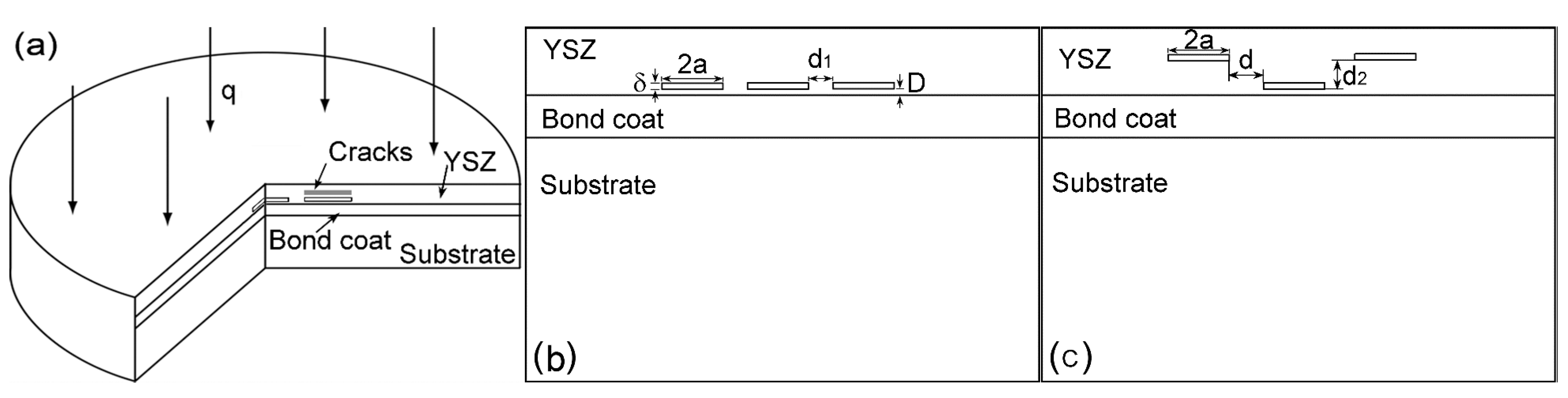
A cylindrical three-dimensional Finite-Element Model (FEM) was fabricated to evaluate the temperature distribution in TBC with coalescing cracks, as shown in Figure 1a. The model has been described in detail in our previous report [6,7] and will therefore be outlined here only shortly. The FEM included three layers: substrate, bond coat, and YSZ coating; the associated thicknesses of the three layers were 3.0 mm, 150 μm, and 250 μm, respectively. Penny-cracks with two different types were introduced into the model, respectively. The first type was that the cracks with an identical depth in YSZ coating were introduced into the model to illustrate the change of temperature distribution with inplane cracks coalescing, as shown in Figure 1b. All crack lengths (2a) in this model were fixed to be 2.0 mm. Associated crack widths (δ) were all 20 μm, depending on the ratio of crack length versus its width [33]. The various distances (d1) between adjacent edges of two cracks ranged from “0a” to “3.0a” were designed. Associated unit of the distance is millimeters (mm). Additionally, the cracks in the model were located in the YSZ coating with distance (D) to interface of 20 μm in term of location depth. In order to clarify the influence of cracking paths on temperature distribution, the second-type model with three penny-shaped cracks of different depths was conducted into YSZ coating. The middle crack located in YSZ coating with distance to interface of 20 μm, and, correspondingly, the depths of the other two cracks changed along YSZ thickness, as shown in Figure 1c. The distance (d2) between middle crack and side crack along YSZ thickness increased from 0 to 150 μm. Meanwhile, the inplane distance between edge of central crack and that of side crack (d) was 2.0 mm.
2.2. The Boundary Conditions and Heat Load
The roughness on both surfaces of substrate and bond coat was neglected during calculation. The thermal-expansion increments among layers were different, inducing local inplane slipping between layers. The local slipping in this model was ignored. Meanwhile, the radiation and convection within crack were ignored [7] and the boundary of model was supposed to be adiabatic. On the basis of the result that the high-temperature stage can be considered as a steady-state heat transfer, and the heat-flux density can be calculated by the simplified heat-transfer formula. The calculated heat-flux density (q, 0.66 × 10⁶ W/m2) was loaded on the YSZ free surface. The thermal properties of YSZ coating exhibit anisotropy because of its typical laminar structure [1,2,10,11,12,13,14,15,22,23,24,25,34]. As a result, the thermal conductivity of plasma-sprayed YSZ coating along thickness is different from that of inplane. The thermal conductivity of the bond coat in the case corresponds to the MCrAlTaY (Metco Amdry 997) and that of the substrate corresponds to the nickel-based superalloy (Inconel 738). The thermal conductivity of layers used in the model is shown in Table 1 [7].
3. Results and Discussion
3.1. The Temperature Distribution in YSZ Coating with Coalescing Cracks
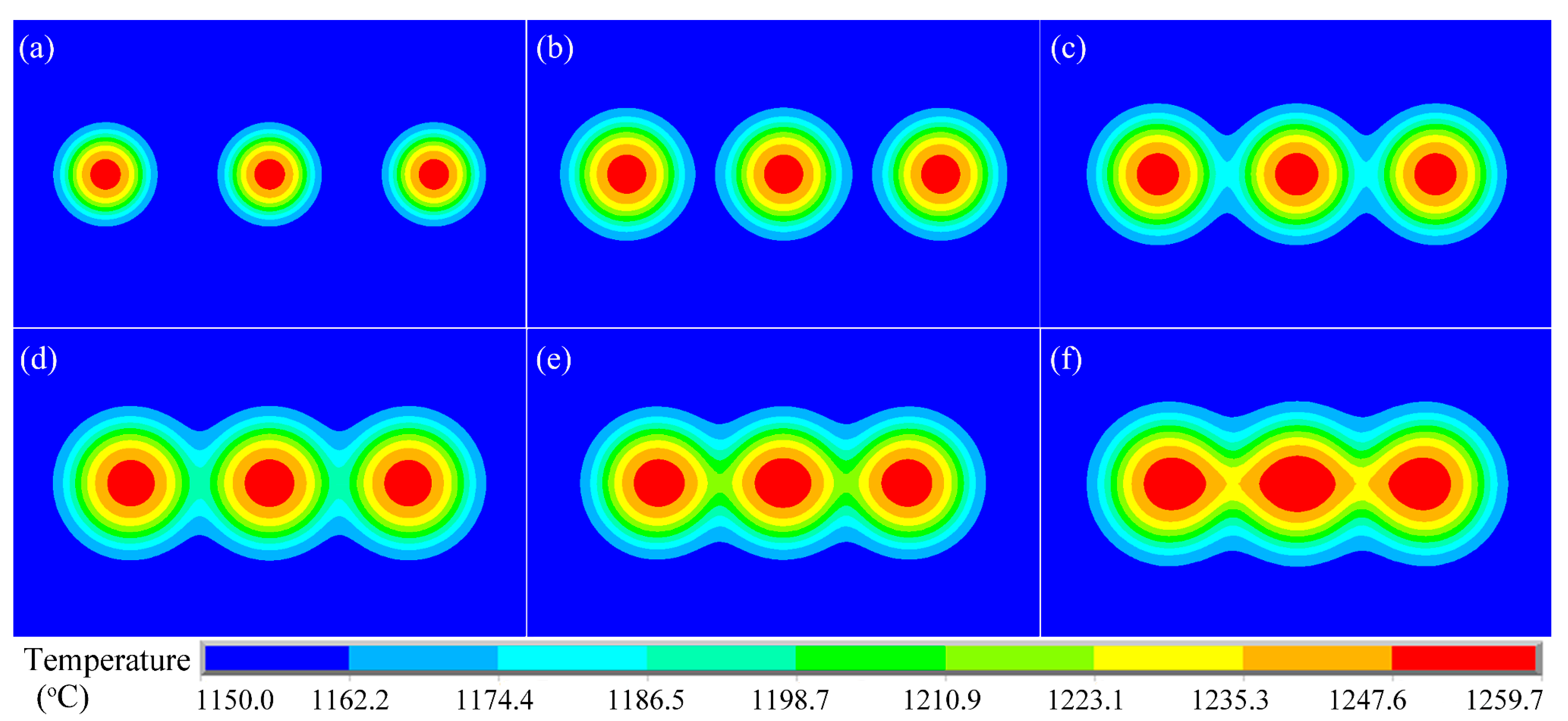
Figure 2 shows the temperature distribution on the YSZ free surface depending on the distance of cracks. The results show that the regions of temperature rose over the cracks, independent of each other when two cracks had enough distance. It means that the elevated temperatures corresponding to the delamination crack were independent from each other at the beginning of crack propagation. The area of the elevated temperature over the crack followed the crack shape. As a result, the region of the elevated temperature could be considered as a union of numerous circular isothermals, and the maximum temperature corresponded to the center of the crack. As crack distance shortened, the regions of temperature rose corresponding to the cracks contacting and overlapping each other. As a result, the isothermals no longer perfectly followed the crack shape, as shown in Figure 2. The results indicate that the independent elevated-temperature regions started to overlap due to crack propagation. Consequently, compared with the other crack-free regions, the sintering rate of YSZ between cracks increased although this region was also crack-free. The architecture (i.e., microcrack healing [6,9,10,13] and bonding of intersplat during thermal spraying [10,35]) induced by sintering caused the stiffening of YSZ. Associated energy-release rate increased, depending on increasing elastic modulus [6,11,16,36]. In addition, the corresponding thermal conductivity of YSZ in the region increased, reducing the thermal protection offered to the bond coat [37,38]. Moreover, the YSZ coating between cracks partly sintered before crack coalescence due to the temperature overlap. Thus, vertical cracks induced by sintering [6] would generate rapidly in this region once two cracks coalesced. Therefore, the temperature overlap partly affected the durability of TBC via the increasing sintering rate, and will therefore be discussed in detail in below section.
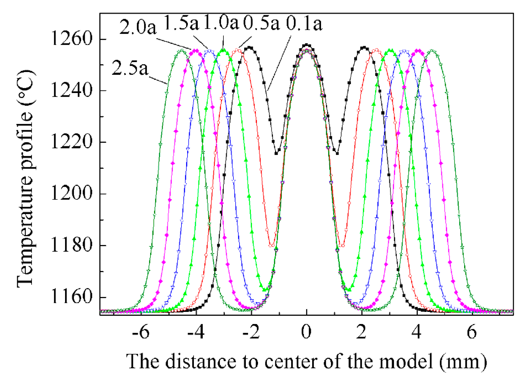
In order to address how the overlap affects temperature distribution, the temperature profiles along crack lengths were examined, as shown in Figure 3. In spite of no recognizable expression in the temperature field shown in Figure 2b, the temperature fields over the cracks did indeed have a role on each other. The majority heat transfer across the YSZ had to make a detour from the crack tip, because of the much lower thermal conductivity of the air in the delamination crack. This heat transfer overlaps when distance between two cracks ranges in a critical value, inducing a temperature rise in the YSZ between cracks. The increasing temperature between cracks induced an increasing driving force for YSZ sintering, then improved the sintering rate. It is interesting that the maximum temperature on the YSZ free surface still corresponded to the crack center, and the maximum temperature had no significant change with shortening crack distance. It means that YSZ coating over the center of a small crack prioritized sintering before cracks coalesced. This result can explain why a fraction of small vertical cracks sometimes did not distribute around the center of the large coalesced crack [6].
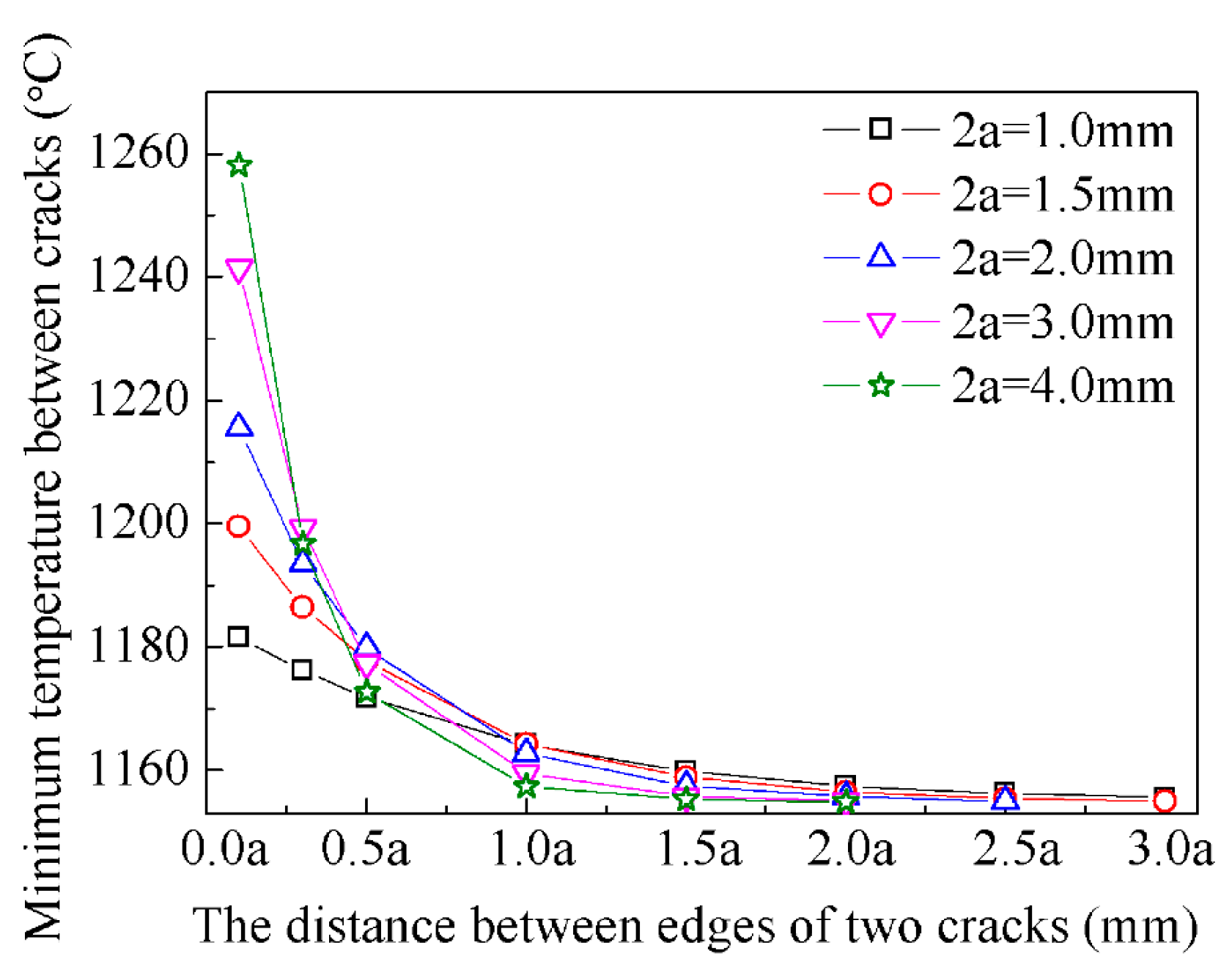
Figure 4 shows the minimum temperatures between two cracks with different distances. The results show that the minimum temperature was identical to the service temperature of as-sprayed YSZ when cracks were distant, as the distance shortened, and the temperature increased. In this paper, the critical distance is defined as the distance that the temperatures over cracks were perfectly independent from each other. Thus, the critical distance is appropriately equal to the crack length when the lengths of two cracks are comparable. Actually, the two crack lengths are various before coalescence. Thus, it is more significant to clarify the critical distance between two cracks with different lengths. The critical distance deduced via Figure 4 can be separated into two parts; the dimension of each temperature-rise area is about the half of the crack length. Thus, the critical distance is the sum of the half-lengths of two coalescing cracks (i.e., a1 + a2) when cracks with different lengths propagate to each other.
The sintering rate of YSZ between cracks increases with crack propagating, resulting in the elastic modulus increasing. On the basis of the data handling in the report [39], the evolution of elastic modulus, E, depended on sintering temperature, can be described by following formula:
where T represents the sintering temperature, and a, b, c are the fitting constants dependent on YSZ initial microstructure, sintering time and stress state, etc., which are in the range of 16–21, 8 × 10−50–10−47, and 15–16, respectively. The constant a presents the elastic modulus of as-sprayed YSZ coating via the test method in Reference [39].
The elastic modulus of YSZ corresponding to the different temperatures could be evaluated via Equation (1). Thus, in order to evaluate the increasing degree of energy-release rate merely induced by heat-transfer overlapping, the elastic modulus in crack-free regions with different distances to crack tip with and without heat-transfer overlapping were evaluated. The minimum temperatures between cracks were selected to calculate elastic modulus, i.e., the corresponding distance to crack tip is the half of the distance between cracks. Correspondingly, the second typical temperatures used in the case derive from the results of the delamination cracks [6]. It is worth pointing out that these two typical temperatures were from the regions that are identical distances to crack tips.
The fracture toughness of YSZ coating increases with increasing sintering degree of YSZ [6,40]. Thus, both cracking driving force and cracking resisting force increases with the sintering of YSZ. The influence of sintering of YSZ on durability of TBC is a fighting process between driving force and resisting force. The driving force was quantitatively evaluated in this case. The elastic modulus evaluated in the case was used to calculate the strain energy-release rate. The strain energy-release rate, Gh, is introduced to provide a quantitative description of driving force [11,16,41]:
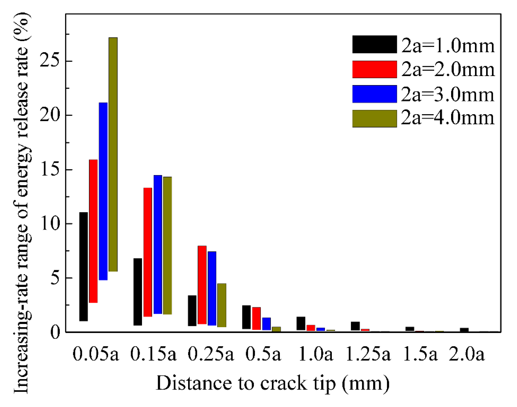
where h is the YSZ thickness, ε is the strain, υ refers to the Poisson’s ratio, Δα is the thermal expansion coefficient between YSZ and substrate, and ΔT is the temperature range. On the basis of elastic-modulus calculation, the strain energy release rate was calculated merely in term of elastic modulus induced by YSZ sintering. Figure 5 shows the range of increasing rate of energy-release rate in different crack-free regions before and after heat-transfer overlapping. The increment of strain energy-release rate can be neglected when the distance to crack tip exceeds the half of the crack length, 1.0a. The increasing rate of energy-release in the region with a distance to the crack tip of 1.0a is the range of 0.2%–1.0% when crack length is larger than 1.0 mm. As a crack propagates, i.e., the distance shortens, the strain energy-release rate in regions that heat transfer overlaps increases at various level. The increasing rate approaches 1.2%–28% when distance is 0.05a, depending on the crack length. However, the crack edge distance of 0.1a corresponding to the 0.05a in the case can not, indeed, keep for a long period because of the sudden coalescing. Thus, the increasing rate of energy release merely induced by increasing elastic modulus of YSZ is approximately 0.2%–15%, depending mainly on the crack length and the crack distance, as shown in Figure 5. In comparison, the additional thermal expansion misfit caused by temperature increment over the crack induces increment of the strain energy-release approach 10% when crack length is 1.0 mm [6]. Thus, the effect of stiffening induced by sintering on strain energy-release rate is on some level comparable to that of deterioration of thermal-expansion misfit induced by a temperature jump, both of which affect strain energy-release rate dramatically and increase with increasing crack length.
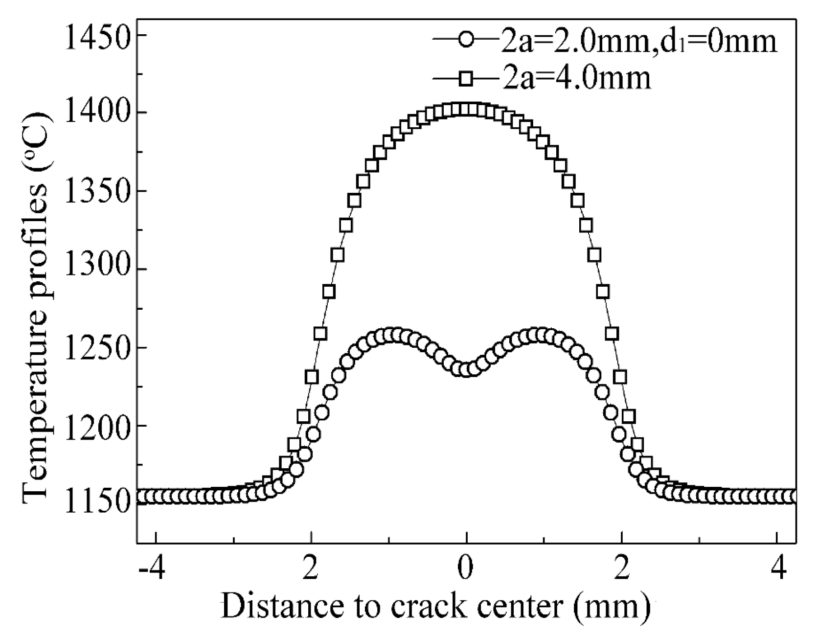
Figure 6 shows the temperature profiles of cracks before and after coalescence. The maximum temperature over the crack with a length of 2 mm in the case was about 1250 °C when two cracks just contacted each other. In comparison, the maximum temperature over the crack with a length of 4 mm exceeded 1400 °C. It signifies that the maximum temperature over the crack rose sharply accompanied with crack coalescence. As a result, crack coalescence dramatically improved the rate of sintering of YSZ coating. The lateral tension in YSZ coating induced by YSZ sintering [6,16] accelerates delamination cracking and also induces the vertical cracking. The morphology of vertical cracks is fairly analogous to that of segmentation cracks [42,43,44], while their effect on the durability of TBC is the opposite. The oxidation rate of bond coat under the vertical crack dramatically accelerates, the mixed oxides deteriorated the durability of TBC [45,46,47] locally generated under the vertical crack.
3.2. The Temperature Distribution Depended on Distance Between Cracks Across YSZ Coating
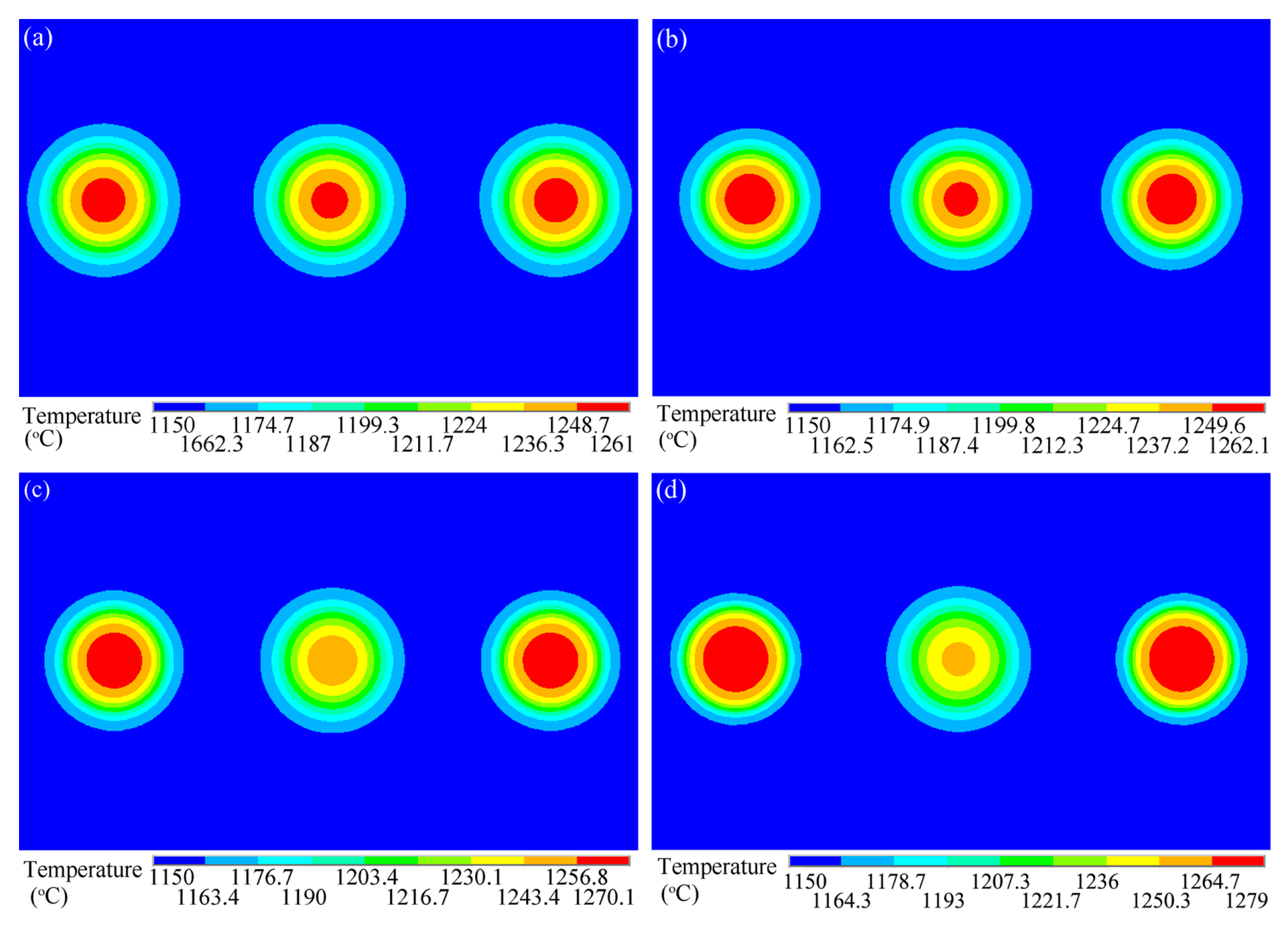
In order to clarify whether the relative depths of the cracks affect the critical distance that the temperatures over cracks are perfectly independent from each other, the influence of the distance between two cracks along YSZ thickness on temperature distribution was addressed, as shown in Figure 7. The inplane distance between cracks in the case was fixed to be the critical distance defined in the above section (i.e., a1 + a2). The results show no recognizable correlation between two elevated temperature regions over the cracks. It is in accordance with the result corresponding to the cracks in the absence of depth variation, as shown in Figure 2a. It indicates that the relative depths of the cracks maybe contribute little to the critical distance. A detailed discussion will be elaborated below. Compared with cracks in identical depth, the maximum temperature locates the center of the side crack, and the maximum temperature increases as the crack moves to the YSZ-coating free surface. Thus, the sintering rate of the YSZ coating increases as the cracking path moves to the YSZ-coating free surface.
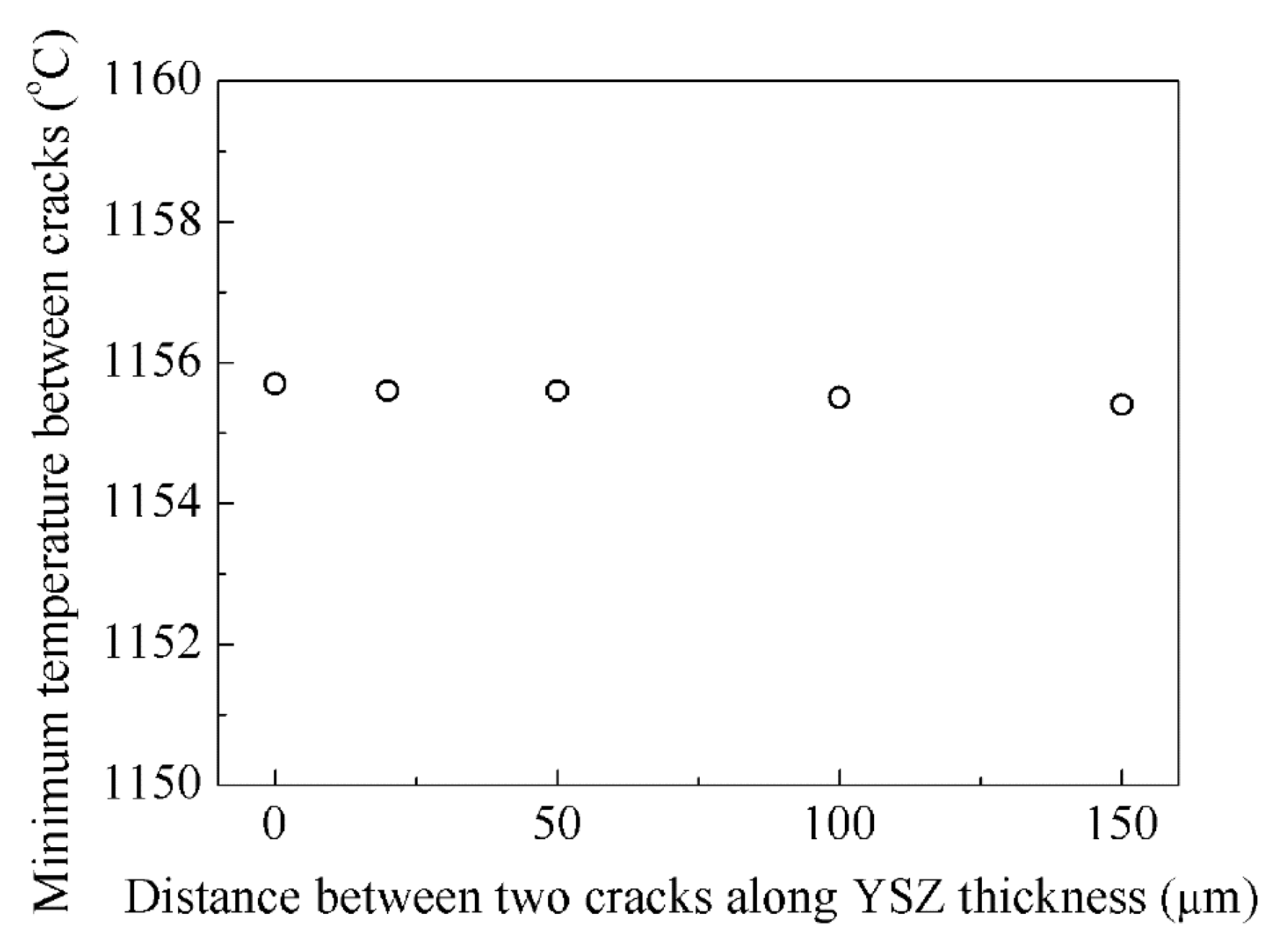
The minimum temperature between two cracks in Figure 7 was plotted, as shown in Figure 8. The inplane distance between two cracks in this case was fixed to be the sum of halves of two crack lengths (i.e., a1 + a2). These minimum temperatures are all comparable. Thus, the critical distance that the temperature regions over cracks just overlap can be considered as the sum of the half-lengths of two cracks, which is independent of the relative depths of the cracks.
4. Conclusions
A three-dimensional FEM was established to evaluate the influence of multicracks on temperature distribution characteristic in plasma-sprayed thermal-barrier coatings. The main results from this model are outlined here. The temperature rises of the YSZ coating over the crack were independent from each other at the beginning of crack propagation. As cracks propagated, the independent elevated-temperature regions started to overlap. The critical distance of the regions of temperature rises, just overlapping, was the sum of half-lengths of two coalescing cracks (i.e., a1 + a2), which was independent of the cracking path in TBC. The maximum temperature was still located at the crack center before crack coalescence, in spite of heat-transfer overlapping between crack tips. The maximum temperature on the YSZ free surface sharply increased once cracks coalesced.
Compared with one delamination crack, the heat-transfer overlapping around the crack tips appreciably increased the strain energy-release rate via the sintering of the YSZ coating. The effective energy-release rate merely induced by sintering of the YSZ increased in the range of 0.2%–15%, depending mainly on the crack length and the crack distance. The effect of stiffening induced by sintering on strain energy-release rate was on some level comparable to that of the deterioration of a thermal expansion misfit induced by a temperature jump between two crack faces.
Author Contributions
Conceptualization, H.D. and Y.H.; Data Curation, H.D.; Formal Analysis, J.-T.Y. and Y.L.; Investigation, H.D.; Methodology, Y.Z.; Resources, X.L.; Software, H.D. and Y.H.; Validation, Y.Z.; Writing-Original Draft, H.D.; Writing-Review & Editing, X.L.
Funding
The research was funded by the National Natural Science Foundation of China (No. 51605384), Natural Science Foundation Research Project of Shaanxi Province (No. 2017JQ5042), Materials Science and Engineering of Provincial Advantage Disciplines in Xi’an Shiyou University (No. YS37020203), and State Key Laboratory of Materials Processing and Die and Mould Technology, Huazhong University of Science and Technology (No. P2018-17).
Acknowledgments
The guidance and help of An-Qing Fu and Cheng-Xian Yin from CNPC Tubular Goods Research Institute are greatly acknowledged.
Conflicts of Interest
The authors declare no conflict of interest.
References
- Padture, N.P.; Gel, M.; Jordan, E.H. Thermal barrier coatings for gas-turbine engine applications. Science 2002, 296, 280–284. [Google Scholar] [CrossRef] [PubMed]
- Miller, R.A.; Lowell, C.E. Failure mechanisms of thermal barrier coatings exposed to elevated temperatures. Thin Solid Films 1982, 95, 265–273. [Google Scholar] [CrossRef] [Green Version]
- Hu, N.; Khan, M.; Wang, Y.; Lin, C.; Chang, C.; Zeng, Y. Effect of microstructure on the thermal conductivity of plasma sprayed Y2O3 stabilized zirconia (8% YSZ). Coatings 2017, 7, 198. [Google Scholar] [CrossRef]
- Zhou, D.; Guillon, O.; Vaßen, R. Development of YSZ thermal barrier coatings using axial suspension plasma spraying. Coatings 2017, 7, 120. [Google Scholar] [CrossRef]
- Prapamonthon, P.; Xu, H.; Yang, W.; Wang, J. Numerical study of the effects of thermal barrier coating and turbulence intensity on cooling performances of a nozzle guide vane. Energies 2017, 10, 362. [Google Scholar] [CrossRef]
- Dong, H.; Yao, J.T.; Li, X.; Zhou, Y.; Li, Y.B. The sintering behavior of plasma-sprayed YSZ coating over the delamination crack in low temperature environment. Ceram. Int. 2018, 44, 3326–3332. [Google Scholar] [CrossRef]
- Dong, H.; Yang, G.J.; Cai, H.N.; Li, C.X.; Li, C.J. Propagation feature of cracks in plasma-sprayed YSZ coatings under gradient thermal cycling. Ceram. Int. 2015, 41, 3481–3489. [Google Scholar] [CrossRef]
- Bolu, G.; Gachagan, A.; Pierce, G.; Harvey, G. Reliable thermosonic inspection of aero engine turbine blades. Insight Non-Destr. Test. Cond. Monit. 2010, 52, 488–493. [Google Scholar] [CrossRef]
- Paul, S. Stiffness of plasma sprayed thermal barrier coatings. Coatings 2017, 7, 68. [Google Scholar] [CrossRef]
- Yang, G.J.; Chen, Z.L.; Li, C.X.; Li, C.J. Microstructural and mechanical property evolutions of plasma-sprayed YSZ coating during high-temperature exposure: Comparison study between 8YSZ and 20YSZ. J. Therm. Spray Technol. 2013, 22, 1294–1302. [Google Scholar] [CrossRef]
- Cheng, B.; Yang, N.; Zhang, Q.; Zhang, Y.M.; Chen, L.; Yang, G.J.; Li, C.X.; Li, C.J. Sintering induced the failure behavior of dense vertically crack and lamellar structured TBCs with equivalent thermal insulation performance. Ceram. Int. 2017, 43, 15459–15465. [Google Scholar] [CrossRef]
- Li, G.; Yang, G.; Li, C.; Li, C. A comprehensive sintering mechanism for thermal barrier coatings-Part III: Substrate constraint effect on healing of 2D pores. J. Am. Ceram. Soc. 2018, 101, 3636–3648. [Google Scholar] [CrossRef]
- Yang, G.J.; Li, C.X.; Hao, S.; Xing, Y.Z.; Yang, E.J.; Li, C.J. Critical bonding temperature for the splat bonding formation during plasma spraying of ceramic materials. Surf. Coat. Technol. 2013, 235, 841–847. [Google Scholar] [CrossRef]
- Li, G.R.; Yang, G.J.; Li, C.X.; Li, C.J. Force transmission and its effect on structural changes in plasma-sprayed lamellar ceramic coatings. J. Eur. Ceram. Soc. 2017, 37, 2877–2888. [Google Scholar] [CrossRef]
- Duan, Y.; Zhao, L.; Zhang, Z.; Cui, H.; Gao, Y. Preparation of yttria-stabilized zirconia hollow sphere with reduced shell thickness by controlling ambient temperature during plasma process. Coatings 2018, 8, 245. [Google Scholar] [CrossRef]
- Cheng, B.; Zhang, Y.M.; Yang, N.; Zhang, M.; Chen, L.; Yang, G.J.; Li, C.X.; Li, C.J. Sintering-induced delamination of thermal barrier coatings by gradient thermal cyclic test. J. Am. Ceram. Soc. 2017, 100, 1820–1830. [Google Scholar] [CrossRef]
- Li, G.R.; Yang, G.J.; Li, C.X.; Li, C.J. Sintering characteristics of plasma-sprayed TBCs: Experimental analysis and an overall modelling. Ceram. Int. 2018, 44, 2982–2990. [Google Scholar] [CrossRef]
- Li, G.R.; Yang, G.J.; Chen, X.F.; Li, C.X.; Li, C.J. Strain/sintering co-induced multiscale structural changes in plasma-sprayed thermal barrier coatings. Ceram. Int. 2018, 44, 14408–14416. [Google Scholar] [CrossRef]
- Zhu, J.; Ma, K. Microstructural and mechanical properties of thermal barrier coating at 1400 °C treatment. Theor. Appl. Mech. Lett. 2014, 4, 021008. [Google Scholar] [CrossRef]
- Cernuschi, F.; Bison, P.; Mack, D.E.; Merlini, M.; Boldrini, S.; Marchionna, S.; Capelli, S.; Concari, S.; Famengo, A.; Moscatelli, A.; et al. Thermo-physical properties of as deposited and aged thermal barrier coatings (TBC) for gas turbines: State-of-the art and advanced TBCs. J. Eur. Ceram. Soc. 2018, 38, 3945–3961. [Google Scholar] [CrossRef]
- Shian, S.; Sarin, P.; Gurak, M.; Baram, M.; Kriven, W.M.; Clarke, D.R. The tetragonal-monoclinic, ferroelastic transformation in yttrium tantalate and effect of zirconia alloying. Acta Mater. 2014, 69, 196–202. [Google Scholar] [CrossRef] [Green Version]
- Zhang, W.W.; Li, G.R.; Zhang, Q.; Yang, G.J. Comprehensive damage evaluation of localized spallation of thermal barrier coatings. J. Adv. Ceram. 2017, 6, 230–239. [Google Scholar] [CrossRef] [Green Version]
- Wang, Q.; Yan, Z.; Guo, L.; Ye, F. Phase composition, thermal conductivity, and toughness of TiO2-doped, Er2O3-stabilized ZrO2 for thermal barrier coating applications. Coatings 2018, 8, 253. [Google Scholar] [CrossRef]
- Li, C.J.; Dong, H.; Ding, H.; Yang, G.J.; Li, C.X. The correlation of the TBC lifetimes in burner cycling test with thermal gradient and furnace isothermal cycling test by TGO effects. J. Therm. Spray Technol. 2017, 26, 378–387. [Google Scholar] [CrossRef]
- Dong, H.; Yang, G.J.; Li, C.X.; Luo, X.T.; Li, C.J. Effect of TGO thickness on thermal cyclic lifetime and failure mode of plasma-sprayed TBCs. J. Am. Ceram. Soc. 2014, 97, 1226–1232. [Google Scholar] [CrossRef]
- Dwivedi, G.; Yang, T.; Viswanathan, V.; Sampath, S. Process-property relationship for air plasma-sprayed gadolinium zirconate coatings. J. Therm. Spray Technol. 2015, 24, 454–466. [Google Scholar] [CrossRef]
- Viswanathan, V.; Dwivedi, G.; Sampath, S. Multilayer, multimaterial thermal barrier coating systems: Design, synthesis, and performance assessment. J. Am. Ceram. Soc. 2015, 98, 1769–1777. [Google Scholar] [CrossRef]
- Cheng, B.; Yang, G.J.; Zhang, Q.; Yang, N.; Zhang, M.; Zhang, Y.M.; Li, C.X.; Li, C.J. Gradient thermal cyclic behaviour of La2Zr2O7/YSZ DCL-TBCs with equivalent thermal insulation performance. J. Eur. Ceram. Soc. 2018, 38, 1888–1896. [Google Scholar] [CrossRef]
- Doleker, K.M.; Ozgurluk, Y.; Karaoglanli, A.C. Isothermal oxidation and thermal cyclic behaviors of YSZ and double-layered YSZ/La2Zr2O7 thermal barrier coatings (TBCs). Surf. Coat. Technol. 2018, 351, 78–88. [Google Scholar] [CrossRef]
- Song, J.; Li, S.; Yang, X.; Qi, H.; Shi, D. Numerical investigation on the cracking behaviors of thermal barrier coating system under different thermal cycle loading waveforms. Surf. Coat. Technol. 2018, 349, 166–176. [Google Scholar] [CrossRef]
- Huang, J.; Wang, W.; Lu, X.; Hu, D.; Feng, Z.; Guo, T. Effect of particle size on the thermal shock resistance of plasma-sprayed YSZ coatings. Coatings 2017, 7, 150. [Google Scholar] [CrossRef]
- Huang, J.; Wang, W.; Lu, X.; Liu, S.; Li, C. Influence of lamellar interface morphology on cracking resistance of plasma-sprayed YSZ coatings. Coatings 2018, 8, 187. [Google Scholar] [CrossRef]
- Ahmadian, S.; Jordan, E.H. Explanation of the effect of rapid cycling on oxidation, rumpling, microcracking and lifetime of air plasma sprayed thermal barrier coatings. Surf. Coat. Technol. 2014, 244, 109–116. [Google Scholar] [CrossRef]
- Tan, Y.; Shyam, A.; Choi, W.B.; Curzio, E.L.; Sampath, S. Anisotropic elastic properties of thermal spray coatings determined via resonant ultrasound spectroscopy. Acta Mater. 2010, 58, 5305–5315. [Google Scholar] [CrossRef]
- Chen, L.; Yang, G.J. Epitaxial growth and cracking of highly tough 7YSZ splats by thermal spray technology. J. Adv. Ceram. 2018, 7, 17–29. [Google Scholar] [CrossRef]
- Dong, H.; Yang, G.J.; Cai, H.N.; Ding, H.; Li, C.X.; Li, C.J. The influence of temperature gradient across YSZ on thermal cyclic lifetime of plasma-sprayed thermal barrier coatings. Ceram. Int. 2015, 41, 11046–11056. [Google Scholar] [CrossRef]
- Curry, N.; Janikowski, W.; Pala, Z.; Vilémová, M.; Markocsan, N. Impact of impurity content on the sintering resistance and phase stability of dysprosia- and yttria-stabilized zirconia thermal barrier coatings. J. Therm. Spray Technol. 2014, 23, 160–169. [Google Scholar] [CrossRef]
- Thibblin, A.; Jonsson, S.; Olofsson, U. Influence of microstructure on thermal cycling lifetime and thermal insulation properties of yttria-stabilized zirconia thermal barrier coatings for diesel engine applications. Surf. Coat. Technol. 2018, 350, 1–11. [Google Scholar] [CrossRef]
- Thompson, J.A.; Clyne, T.W. The effect of heat treatment on the stiffness of zirconia top coats in plasma-sprayed TBCs. Acta Mater. 2001, 49, 1565–1575. [Google Scholar] [CrossRef]
- Dwivedi, G.; Viswanathan, V.; Sampath, S.; Shyam, A.; Curzio, E.L. Fracture toughness of plasma-sprayed thermal barrier ceramics: Influence of processing, microstructure, and thermal aging. J. Am. Ceram. Soc. 2014, 97, 2736–2744. [Google Scholar] [CrossRef]
- Shinozaki, M.; Clyne, T.W. A methodology, based on sintering-induced stiffening, for prediction of the spallation lifetime of plasma-sprayed coatings. Acta Mater. 2013, 61, 579–588. [Google Scholar] [CrossRef]
- Tailor, S.; Upadhyaya, R.; Manjunath, S.Y.; Dub, A.V.; Modi, A.; Modi, S.C. Atmospheric plasma sprayed 7%-YSZ thick thermal barrier coatings with controlled segmentation crack densities and its thermal cycling behavior. Ceram. Int. 2018, 44, 2691–2699. [Google Scholar] [CrossRef]
- Fan, Z.; Wang, K.; Dong, X.; Wang, R.; Duan, W.; Mei, X.; Wang, W.; Cui, J.; Zhang, S.; Xu, C. The role of the surface morphology and segmented cracks on the damage forms of laser re-melted thermal barrier coatings in presence of a molten salt (Na2SO4 + V2O5). Corros. Sci. 2017, 115, 56–67. [Google Scholar] [CrossRef]
- Chen, X.; Wang, X.; Wang, H. Modeling segmentation cracking of a brittle coating due tounderneath periodic eigenstrains. Mech. Res. Commun. 2015, 66, 27–33. [Google Scholar] [CrossRef]
- Zhang, W.; Zhang, J.; Wang, H.; Lou, W.; Liu, X. Influences of Cr and Co on the growth of thermally grown oxide in thermal barrier coating during high-temperature exposure. Coatings 2018, 8, 195. [Google Scholar] [CrossRef]
- Jonnalagadda, K.P.; Erikssona, R.; Yuan, K.; Li, X.H.; Ji, X.; Yu, Y.; Peng, R.L. A study of damage evolution in high purity nano TBCs during thermal cycling: A fracture mechanics based modelling approach. J. Eur. Ceram. Soc. 2017, 37, 2889–2899. [Google Scholar] [CrossRef]
- Liu, Y.Z.; Zheng, S.J.; Zhu, Y.L.; Wei, H.; Ma, X.L. Microstructural evolution at interfaces of thermal barrier coatings during isothermal oxidation. J. Eur. Ceram. Soc. 2016, 36, 1765–1774. [Google Scholar] [CrossRef]
Figure 1.
The schematic model of thermal-barrier coatings (TBC): (a) the penny-shaped cracks in a three-dimensional view; (b) cross-sectional view of the model included cracks with an identical depth; and (c) the model contained cracks with different depths.
Figure 1.
The schematic model of thermal-barrier coatings (TBC): (a) the penny-shaped cracks in a three-dimensional view; (b) cross-sectional view of the model included cracks with an identical depth; and (c) the model contained cracks with different depths.

Figure 2.
The distance of crack edges dependence of temperature distribution on the YSZ free surface: (a) 2.0a; (b) 1.0a; (c) 0.5a; (d) 0.3a; (e) 0.1a; and (f) 0 μm. “a” is the half length of the crack. The lengths of three cracks are all 2.0 mm.
Figure 2.
The distance of crack edges dependence of temperature distribution on the YSZ free surface: (a) 2.0a; (b) 1.0a; (c) 0.5a; (d) 0.3a; (e) 0.1a; and (f) 0 μm. “a” is the half length of the crack. The lengths of three cracks are all 2.0 mm.

Figure 3.
Temperature profiles plotted as a function of the crack distance.

Figure 4.
The minimum temperature between two cracks as a function of the distance between edges of two cracks. “a” is the half length of the crack.
Figure 4.
The minimum temperature between two cracks as a function of the distance between edges of two cracks. “a” is the half length of the crack.

Figure 5.
The influence of heat-transfer overlapping on increasing-rate range of energy-release rate.
Figure 5.
The influence of heat-transfer overlapping on increasing-rate range of energy-release rate.

Figure 6.
The temperature profiles of cracks before and after coalescence.

Figure 7.
The crack distance across the YSZ coating dependent of temperature distribution on the YSZ free surface: (a) 20 μm; (b) 50 μm; (c) 100 μm; and (d) 150 μm. The lengths of cracks and inplane distances between two cracks are all 2 mm.
Figure 7.
The crack distance across the YSZ coating dependent of temperature distribution on the YSZ free surface: (a) 20 μm; (b) 50 μm; (c) 100 μm; and (d) 150 μm. The lengths of cracks and inplane distances between two cracks are all 2 mm.

Figure 8.
The minimum temperature between two cracks as a function of the distance along YSZ thickness, the lengths of cracks, and inplane distances between two cracks are all 2 mm.
Figure 8.
The minimum temperature between two cracks as a function of the distance along YSZ thickness, the lengths of cracks, and inplane distances between two cracks are all 2 mm.


Table 1.
The thermal conductivity used in the model [7].
Table 1.
The thermal conductivity used in the model [7].
| Parameters | Values (W·m−1·K−1) |
|---|---|
| Yttria-stabilized zirconia (YSZ) coating (outplane) | 1.1 |
| YSZ coating (inplane) | 2.2 |
| Bond coat | 16.8 |
| Substrate | 31.1 |
| Air in crack | 0.0915 |
© 2018 by the authors. Licensee MDPI, Basel, Switzerland. This article is an open access article distributed under the terms and conditions of the Creative Commons Attribution (CC BY) license (http://creativecommons.org/licenses/by/4.0/).
Share and Cite
MDPI and ACS Style
Dong, H.; Han, Y.; Zhou, Y.; Li, X.; Yao, J.-T.; Li, Y. The Temperature Distribution in Plasma-Sprayed Thermal-Barrier Coatings During Crack Propagation and Coalescence. Coatings 2018, 8, 311. https://doi.org/10.3390/coatings8090311
AMA Style
Dong H, Han Y, Zhou Y, Li X, Yao J-T, Li Y. The Temperature Distribution in Plasma-Sprayed Thermal-Barrier Coatings During Crack Propagation and Coalescence. Coatings. 2018; 8(9):311. https://doi.org/10.3390/coatings8090311
Chicago/Turabian StyleDong, Hui, Yan Han, Yong Zhou, Xiao Li, Jian-Tao Yao, and Yan Li. 2018. "The Temperature Distribution in Plasma-Sprayed Thermal-Barrier Coatings During Crack Propagation and Coalescence" Coatings 8, no. 9: 311. https://doi.org/10.3390/coatings8090311
Note that from the first issue of 2016, this journal uses article numbers instead of page numbers. See further details here.