Article

Ultra-High Sensitive Strain Sensor Based on Post-Processed Optical Fiber Bragg Grating

1
INESC Porto, Rua do Campo Alegre, 687, Porto 4169-007, Portugal
2
Faculdade de Ciências da Universidade do Porto, Rua do Campo Alegre, 687, Porto 4169-007, Portugal
3
IPHT Jena, Institute of Photonic Technology, Albert-Einstein-Str. 9, Jena 07745, Germany
*
Author to whom correspondence should be addressed.
These authors contributed equally to this work.
Fibers 2014, 2(2), 142-149; https://doi.org/10.3390/fib2020142
Submission received: 28 December 2013 / Revised: 28 March 2014 / Accepted: 8 April 2014 / Published: 14 April 2014

Abstract

:
An ultra-high sensitive strain sensor is proposed. The sensing head, based on the post-processing of a fiber Bragg grating, is used to perform passive and active strain measurements. Both wavelength and full width half maximum dependences with the applied strain are studied for the passive sensor, where maximum sensitivities of 104.1 pm/µε and 61.6 pm/µε are respectively obtained. When combining the high performance of this sensor with a ring laser cavity configuration, the Bragg grating will act as a filter and high resolution measurements can be performed. With the proposed sensor, a resolution of 700 nε is achieved.

1. Introduction

Optical fiber tapers, usually applied in sensors or fiber lasers, can be divided in two groups according to their manufacture: mechanical or chemical tapers. Mechanical tapers, produced by stretching the fiber, present reduced core and cladding diameters. Usually, these structures have a biconical structure. Different fibers have been tapered such as a large-mode-area microstructured fiber [1], suspended-core fiber [2] and large-mode-area holey fiber [3]. The development of these, and other structures, has opened a new window in optical fiber sensing. For instance, the tapering of long period gratings (LPGs) proved to be suitable to measure pressure [4], temperature and strain [5]. In addition, the use of fiber Bragg gratings (FBGs) in tapered fibers was used to measure strain and temperature [6]. A different approach has been proposed by depositing metals in tapered fibers, in order to have surface plasmon resonances [7,8]. The production of an S-tapered fiber sensor led to an axial strain sensor with a maximum sensitivity of −183.4 pm/µε [9].
Chemically etched tapers do not suffer modification of the fiber core, whereas the cladding is partially or totally removed. Besides the biconical tapers [10,11], fiber tip sensors have been proposed. These sensors present high-sensitivity to the environment [12] and are very well suited to perform biosensing [13].
Fiber Bragg gratings have attracted significant attention not only from academia, but also from industry [14]. These structures have been widely explored as sensors as well as optical filters that are suitable, for instance, for application in fiber lasers. The periodical structure is easy to manufacture, reproducible and very straightforward for application in various situations.
In this paper, a sensor based on a post-processed fiber Bragg grating is proposed. The sensing head is subjected to strain measurements, where it exhibits an ultra-high sensitivity. Two different configurations are compared, for passive and active measurements.

2. Experimental Results

A 3 mm long fiber Bragg grating (FBG) was written in photosensitive single mode fiber (SMF) using an excimer laser.
Due to the photosensitivity of the fiber, there was no need to hydrogenate it prior to the grating inscription. The sensing head used was produced by splicing the FBG to the end section of SMF. The end section of the sensor was cleaved, guaranteeing that there were 2 mm of SMF with no inscription between the FBG and the fiber end. This ensured that the post-processing would not destroy the FBG length. The fiber tip with the FBG was then subjected to wet chemical etching, being submerged in a 40% hydrofluoric acid (HF) solution during 55 min. This led to a tapering of the fiber, with a final tip diameter of ~12 µm, and a length of 4.5 mm, accordingly to the scheme of Figure 1a. Due to the strength of the etch near the end face of the fiber tip relative to that throughout the cladding, the sensor acquired a conical shape. Consequently, the reflection spectrum of the grating changed, not only did its Bragg wavelength shift ~10 nm, but also the full width half maximum (FWHM) increased from 0.36 nm to 6.03 nm, see Figure 1b. This chirp behavior had a strong influence in the sensing head response to strain. Due to the predictability of the etching behavior, it was possible to obtain several sensing heads with identical properties.
Figure 1. (a) Fiber tip schematic design; (b) Reflection spectra of the un-etched fiber Bragg gratings (FBG) and the etched FBG.
Fibers 02 00142 g001

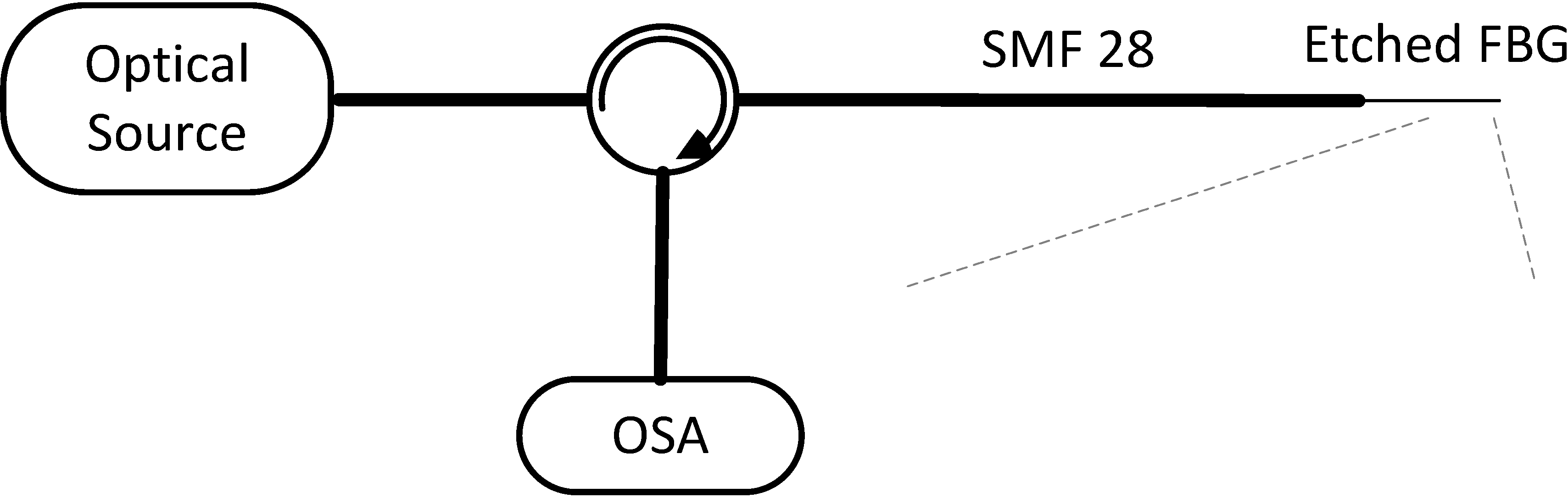
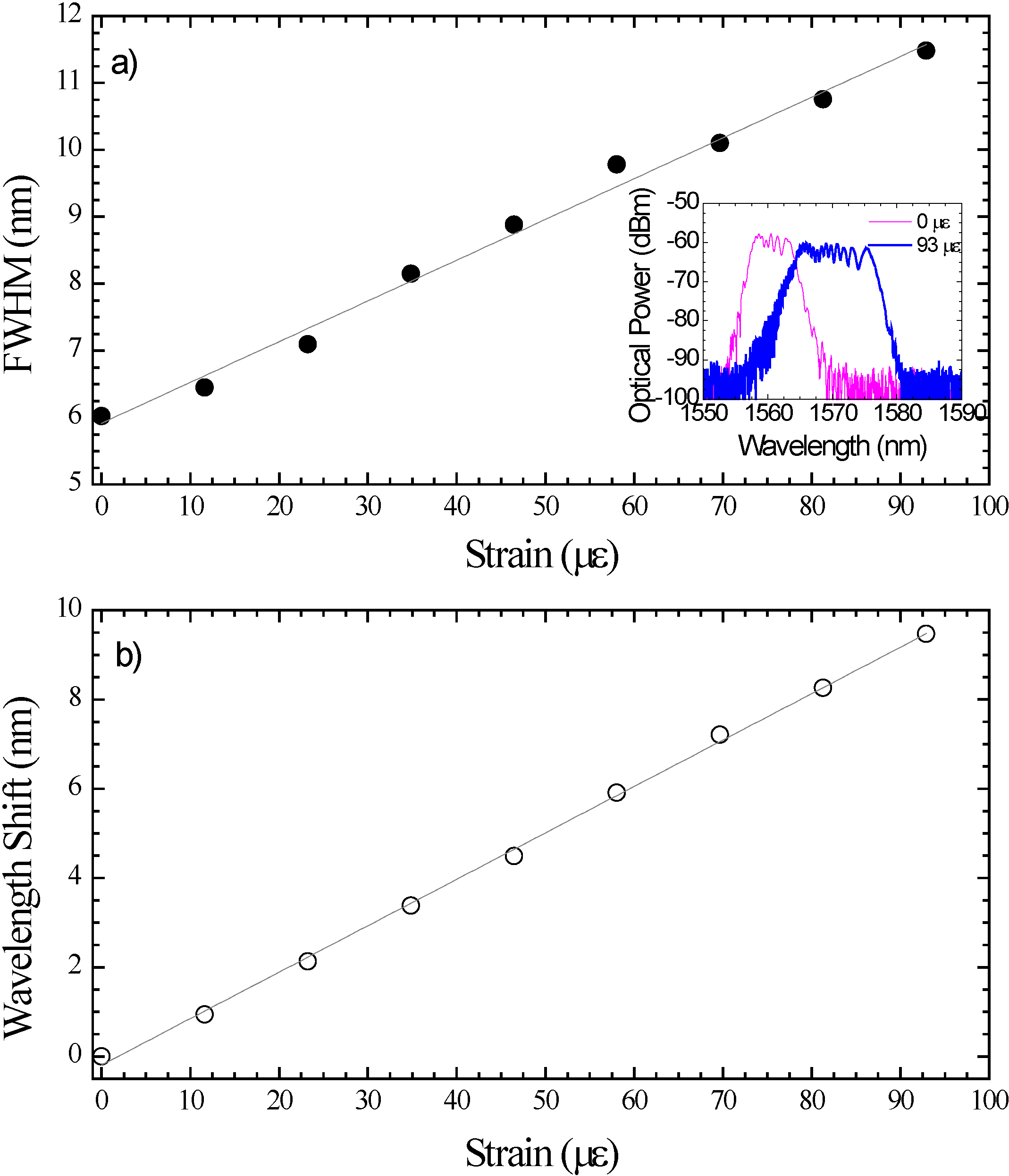
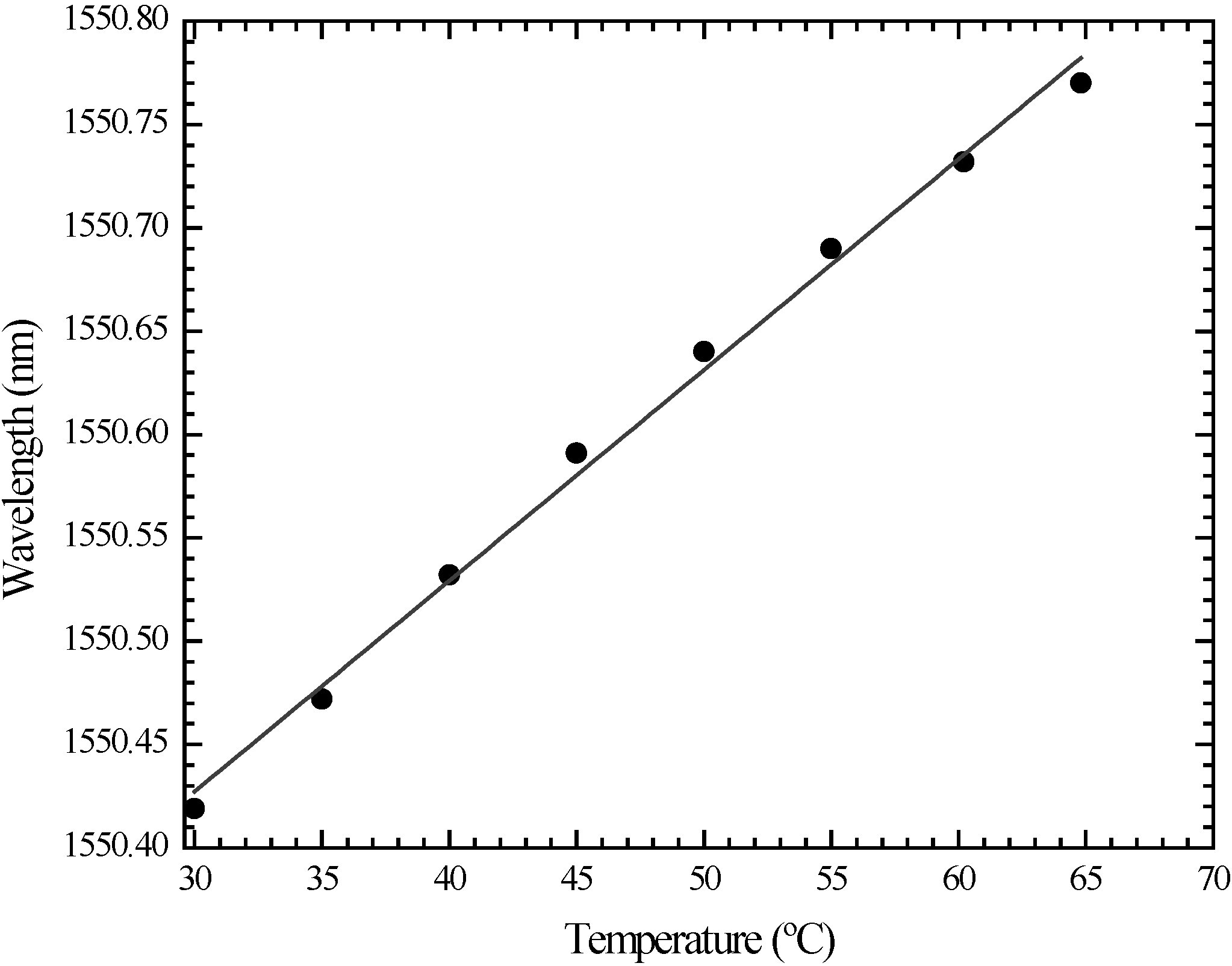
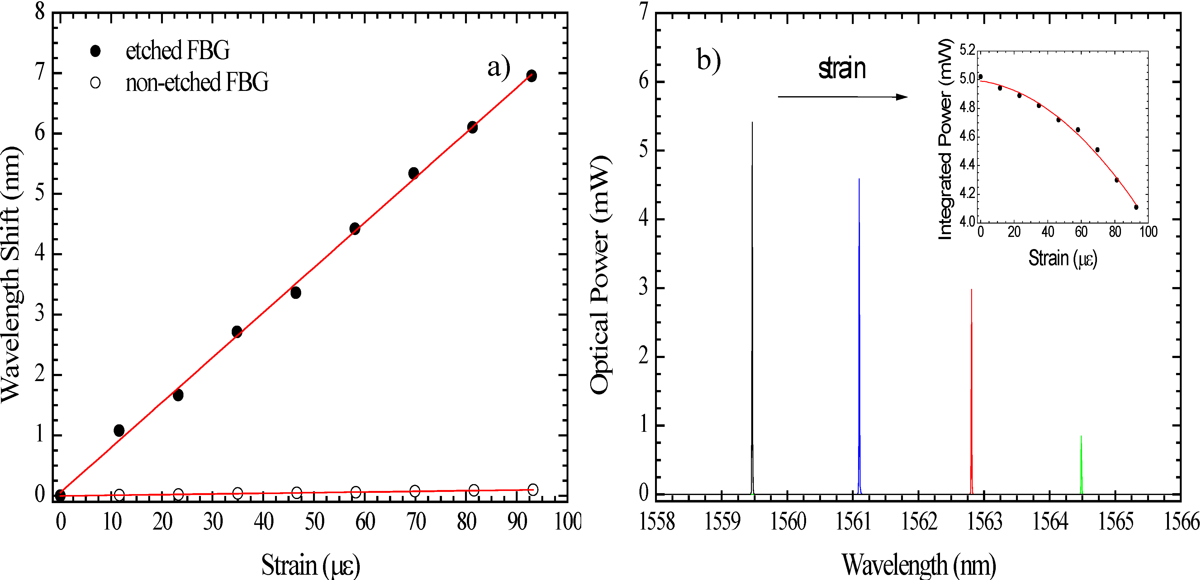
2.1. Ultra-High Sensitivity Strain Sensor

The passive measurements were done by using a typical reflection measurement setup, schematically shown in Figure 2. A broadband optical source centered at 1570 nm and with a bandwidth of 100 nm was connected to an optical circulator. The reflection readings were performed by an optical spectrum analyzer (OSA) with a resolution of 0.01 nm. All measurements were carried out at room temperature (~23 °C).
Figure 2. Strain sensor experimental setup.
Fibers 02 00142 g002
The sensing head was placed in a translation stage with a resolution of 1 µm and strain measurements were performed in a range of 100 µε. Even though the fiber tip was extremely thin, it was relatively easy to handle. As strain was applied, besides a shift of the Bragg wavelength, the spectrum became broader, accordingly to the inset of Figure 3a). In this case, when strain is applied, due to the conical shape of the sensor, the stress is not constant. This translates in the elongation of the FBG periods, with a consequent widening of the range of wavelengths filtered. The analysis of strain measurements can be done from two different points of view, with respect to the FWHM changes and to the wavelength shift. Regarding the FWHM, there is an increase of this parameter with the applied strain, with a linear tendency, according to Figure 3a. The sensitivity is, in this case, of 61.6 pm/µε. Figure 4b presents the Bragg wavelength shift with the applied strain, which presents a linear behavior. In this case, the sensitivity is of 104.1 pm/µε. Thus, with this configuration it is possible to improve ~100 times the sensitivity of a standard FBG [14]. The reason why it was only tested up to 100 µε was the intention of comparing the sensing head behavior in the different situations. However, throughout the experiment higher strain was applied without damaging the fiber.
Figure 3. (a) Full width half maximum (FWHM) variation with the applied strain. Inset: etched FBG optical spectra with no strain applied and with a strain of 93 µε; (b) Bragg wavelength shift with the applied strain.
Fibers 02 00142 g003
Figure 4. Sensing head response to temperature.
Fibers 02 00142 g004
The sensing head was placed in a tubular oven and temperature measurements were done with a resolution of 0.1 °C. The sensor exhibited the same response of a typical un-etched FBG, with a linear sensitivity of 10.2 pm/°C (see Figure 4). It should be noted that in this case no broadening of the spectra was observed, only a shift of the Bragg wavelength. Thus, by taking this effect in temperature and the FWHM changes in strain, it is possible to use this sensing head to perform simultaneous measurement of strain and temperature.

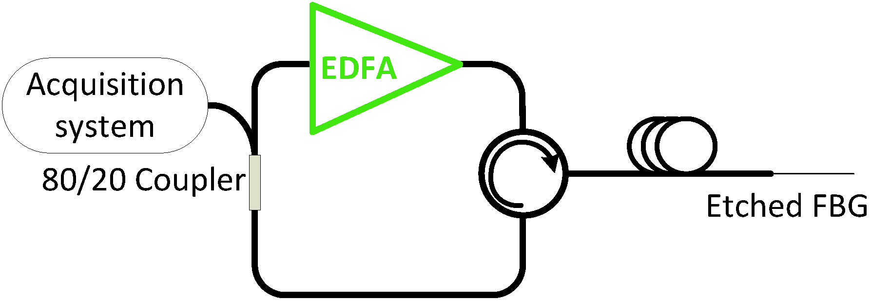
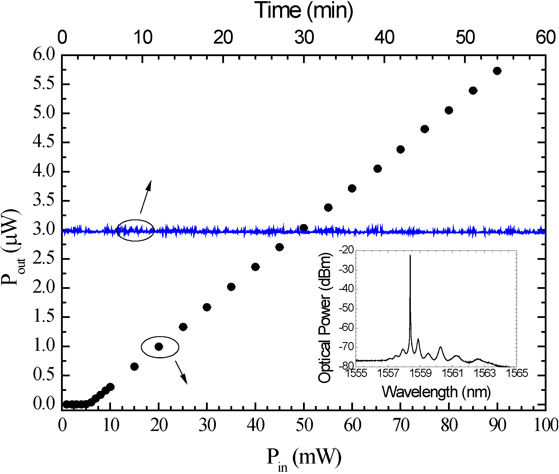
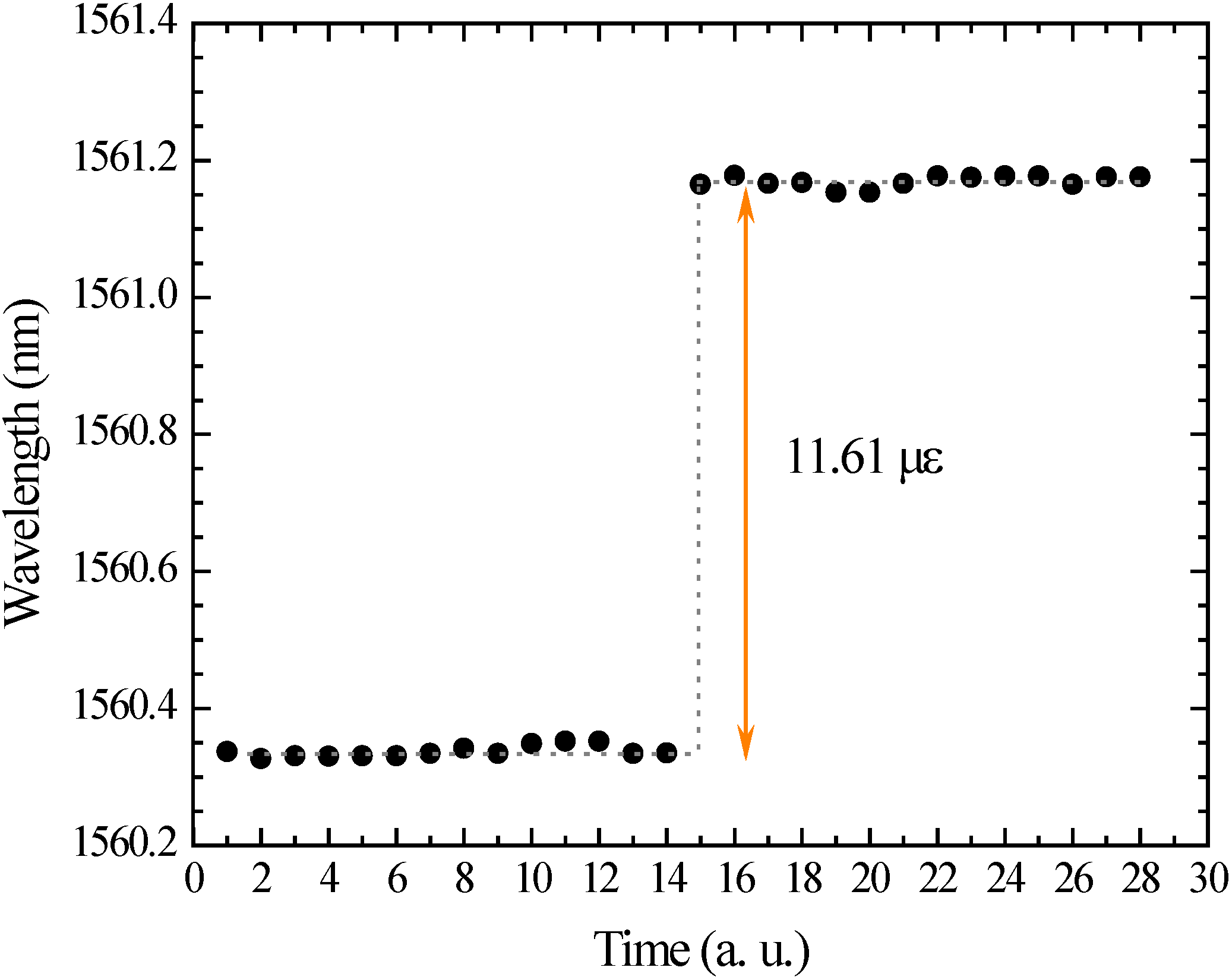
2.2. Fiber Laser Strain Sensor

The same sensing head was included in a fiber ring laser configuration. In this case, the FBG acted as a filter and laser action occurred in the grating spectral region. The experimental setup, depicted in Figure 5, was constituted by an Erbium doped fiber amplifier (EDFA) enclosed between an optical circulator and an 80/20 optical coupler. From the optical circulator, a connection was made to the input port of the optical coupler. The 20% port of this device was connected to the data acquisition system, whereas the 80% arm was connected to the input port of the EDFA. The sensing head was connected to the optical circulator in order to be read in reflection. Depending on the type of measurement, an OSA or a powermeter were used as data acquisition systems.
Figure 5. Fiber laser sensor experimental setup.
Fibers 02 00142 g005
Figure 6. Laser output power as a function of the pump power. Also shown the laser stability for a constant input power of 50 mW, over 60 min. Inset: Fiber laser sensor spectrum.
Fibers 02 00142 g006
The laser exhibited a threshold power of 5.48 mW, an efficiency of 7.4%, and a signal-to-noise ratio (SNR) higher than 50 dB. The stability was studied by fixing the input power at 50 mW and measuring the output power over one hour. A fluctuation of 0.11 mW was observed; however, the emission was quite stable, as can be seen in the blue line of Figure 6.
Strain measurements were done by using the same translation stages as in the passive sensor measurement. The inset of Figure 6 presents the fiber laser spectrum. The laser is emitting in the lower wavelength region of the chirp spectrum (at 1558.4 nm). Since the chirp increases for longer wavelengths, due to the pronouncing of the taper, the active sensor is expected to be less sensitive than the passive one. Nevertheless, if there was a tuning of the lasing wavelength, it would be expectable to achieve higher sensitivities. Figure 7a presents the results obtained for the etched FBG along with the ones measured with a non-etched FBG. The non-etched FBG exhibited a linear sensitivity of 1.1 pm/µε, whilst the etched FBG presented a sensitivity of 74.5 pm/µε. It should be highlighted that throughout the experiments the laser peak did not suffer from mode hopping. As strain was applied, it was observed that the peak optical power decreased, following the EDFA gain curve. Figure 7b shows the spectral shift of the laser peak. The inset in Figure 7b exhibits the integrated power variation with the applied strain measured with the power-meter. The pronounced decrease in the optical power, due to the gain variation of the EDFA represents the main constraint of this sensing head, since above the 100 µε, the filter was placed out of the EDFA gain range and there was no laser emission. Nevertheless, this sensor can also be used to measure variations in optical power, translating in a low-cost, temperature independent and high-sensitive system. Combining the high-sensitivity of this sensing head with the emission characteristics of a fiber laser, it is worth studying its resolution regarding strain measurements. In this context, the resolution of the sensor is shown in Figure 8. In order to determine the resolution, the following equation was used: δε/δλ = 2Δε/Δλ. A step of 11.61 µε Δε) was applied for 30 s, which corresponded to a Δλ of ~0.85 nm. A resolution of 700 nε was attained. This value was mainly limited by the signal acquisition system.
Figure 7. (a) Wavelength dependence on applied strain, for a non-etched FBG and an etched FBG; (b) Laser emission dependence on the applied strain. Inset: integrated power as a function of the applied strain.
Fibers 02 00142 g007
Figure 8. Laser strain sensor resolution.
Fibers 02 00142 g008

3. Conclusions

An optical fiber sensor based on the post-processing of a fiber Bragg grating was proposed. The sensor was characterized as a passive element, where ultra-high strain sensitivity was obtained. However, the signal processing is more complex if a commercial interrogation system is used. When incorporated in a fiber laser, the laser peak varied not only in wavelength, but also in integrated power. In addition, its performance was limited by the EDFA gain curve. However, this sensor presents a very high signal-to-noise ratio, being very suitable for applications in remote sensing and can also be useful as a vibration sensor. In both cases, the sensor presented sensitivity to temperature similar to a standard FBG. Nevertheless, it is possible to use the laser strain sensor with temperature independence, if the optical power variations are considered instead of phase variations.

Acknowledgments

This work was supported in part by the FCT–Fundação para a Ciência e Tecnologia under the grant SFRH/BD/76965/2011 and by COST Action TD1001. This work was supported by project "NORTE-07-0124-FEDER-000058"which is financed by the North Portugal, Regional Operational Programme (ON.2 – O Novo Norte), under the National Strategic Reference Framework (NSRF), through the European Regional Development Fund (ERDF).

Conflicts of Interest

The authors declare no conflict of interest.

References

  1. Villatoro, J.; Minkovich, V.P.; Monzon-Hernandez, D. Compact modal interferometer built with tapered microstructured optical fiber. IEEE Photon. Tech. Lett. 2006, 18, 1258–1260. [Google Scholar] [CrossRef]
  2. André, R.M.; Silva, S.O.; Becker, M.; Schuster, K.; Rothardt, M.; Bartelt, H.; Marques, M.B.; Frazão, O. Strain sensitivity enhancement in suspended core fiber tapers. Photon. Sen. 2013, 3, 118–123. [Google Scholar] [CrossRef]
  3. Villatoro, J.; Minkovich, V.P.; Monzon-Hernandez, D. Temperature-independent strain sensor made from tapered holey optical fiber. Opt. Lett. 2006, 31, 305–307. [Google Scholar] [CrossRef]
  4. Bock, W.J.; Chen, J.; Mikulic, P.; Eftimov, T. A novel fiber-optic tapered long-period grating sensor for pressure monitoring. IEEE Trans. Instrum. Measur. 2007, 56, 1176–1180. [Google Scholar] [CrossRef]
  5. Yoon, M.S.; Kim, H.J.; Kim, S.J.; Han, Y.G. Influence of the waist diameters on transmission characteristics and strain sensitivity of microtapered long-period fiber gratings. Opt. Lett. 2013, 38, 2669–2672. [Google Scholar] [CrossRef]
  6. Silva, S.F.O.; Ferreira, L.A.; Araujo, F.M.; Santos, J.L.; Frazao, O. Fiber bragg grating structures with fused tapers. Fiber Integr. Opt. 2011, 30, 9–28. [Google Scholar] [CrossRef]
  7. Diaz-Herrera, N.; Gonzalez-Cano, A.; Viegas, D.; Santos, J.L.; Navarrete, M.C. Refractive index sensing of aqueous media based on plasmonic resonance in tapered optical fibres operating in the 1.5 mu m region. Sens. Actuat. B Chem. 2010, 146, 195–198. [Google Scholar] [CrossRef]
  8. Verma, R.K.; Sharma, A.K.; Gupta, B.D. Modeling of tapered fiber-optic surface plasmon resonance sensor with enhanced sensitivity. IEEE Photon. Tech. Lett. 2007, 19, 1786–1788. [Google Scholar] [CrossRef]
  9. Yang, R.; Yu, Y.S.; Chen, C.; Xue, Y.; Zhang, X.L.; Guo, J.C.; Wang, C.; Zhu, F.; Zhang, B.L.; Chen, Q.D.; et al. S-tapered fiber sensors for highly sensitive measurement of refractive index and axial strain. J. Lightw. Technol. 2012, 30, 3126–3132. [Google Scholar] [CrossRef]
  10. Putha, K.; Dantala, D.; Kamineni, S.; Pachava, V.R. Etched optical fiber vibration sensor to monitor health condition of beam like structures. Photon. Sens. 2013, 3, 124–130. [Google Scholar] [CrossRef]
  11. Yun, B.F.; Chen, N.; Cui, Y.P. Highly sensitive liquid-level sensor based on etched fiber Bragg grating. IEEE Photon. Tech. Lett. 2007, 19, 1747–1749. [Google Scholar] [CrossRef]
  12. Raikar, U.S.; Kulkarni, V.K.; Lalasangi, A.S.; Madhav, K.; Asokan, S. Etched fiber Bragg grating as ethanol solution concentration sensor. Optoelectron. Adv. Mater. 2007, 1, 149–151. [Google Scholar]
  13. Gao, H.H.; Chen, Z.P.; Kumar, J.; Tripathy, S.K.; Kaplan, D.L. Tapered fiber tips for fiber optic biosensors. Opt. Eng. 1995, 34, 3465–3470. [Google Scholar] [CrossRef]
  14. Kersey, A.D.; Davis, M.A.; Patrick, H.J.; LeBlanc, M.; Koo, K.P.; Askins, C.G.; Putnam, M.A.; Friebele, E.J. Fiber grating sensors. J. Lightw. Technol. 1997, 15, 1442–1463. [Google Scholar] [CrossRef]

