Article

Manufacturing and Spectral Features of Different Types of Long Period Fiber Gratings: Phase-Shifted, Turn-Around Point, Internally Tilted, and Pseudo-Random

Institute of Applied Physics “Nello Carrara”, National Research Council of Italy (IFAC-CNR), Via Madonna del Piano 10, 50019 Sesto Fiorentino (FI), Italy
*
Author to whom correspondence should be addressed.
Fibers 2017, 5(3), 29; https://doi.org/10.3390/fib5030029
Submission received: 5 July 2017 / Revised: 5 July 2017 / Accepted: 1 August 2017 / Published: 8 August 2017
(This article belongs to the Special Issue Advances in Optical Fibers II)

Abstract

:
The manufacturing and spectral features of different types of long period fiber gratings (LPFGs), ranging from phase-shifted, turn-around point, and internally tilted gratings, to pseudo-random gratings, are described and discussed in detail. LPFGs were manufactured on boron-germanium co-doped photosensitive optical fibers with the point-by-point technique using an excimer KrF laser operating at 248 nm. The developed experimental setup to manufacture high-quality LPFGs was designed to totally customize any type of gratings with the possibility of setting different parameters, such as the grating period (or pitch), the number of grating planes, the number of laser shots for each plane, etc. Some important spectral features of the LPFGs’ spectra were taken into account. This allows realizing homemade devices useful in several fiber-based applications, such as optical filtering, coupling systems, random lasers, physical and chemical sensing, and biosensing.

1. Introduction

The continuous and increasing request of compact, portable, lightweight, high-performance devices is pushing both the research and industrial community to develop novel sensing concepts and platforms. Those based on optical fibers are surely interesting due to their intrinsic and typical features [1,2,3]. Moreover, the possibility of realizing resonant photonic structures or selective light coupling systems within an optical fiber increased the dissemination of fiber-based applications [4]. One of the most interesting and widespread approach to develop an integrated fiber-based device regards the manufacturing of a periodic modulation of the refractive index (RI) within the core of a single-mode fiber, better known as an optical fiber grating (OFG). OFGs are classified into two groups: fiber Bragg gratings (FBGs), where the grating period Λ (i.e., the distance between two consecutive modulations) is of the order of hundreds of nm, and long-period fiber gratings (LPFGs), where Λ is of the order of hundreds of μm. There is no competition between them; in fact, both the configurations are extensively used in several fields, ranging from telecommunication applications (optical filtering, coupling systems, random lasers, etc.) [5,6,7,8,9,10,11] up to sensing applications (physical, chemical and biological sensors, etc.) [12,13,14,15,16]. However, given the easier and cheaper customization of LPFGs’ manufacturing process, the topic of this paper will be entirely focused on them.
Looking at Figure 1, the light coupling inside a standard LPFG due to the induced RI modulation inside the fiber core occurs according to the characteristic equation when the phase-matching condition (PMC) between the fundamental core mode and the m-th cladding mode is reached [17]:
λ r e s   ( m ) = Λ · ( n c o r e e f f n c l a d   ( m ) e f f ) ,
where λ r e s   ( m ) represents the resonance wavelength of the attenuation band at the PMC, Λ is the grating period or pitch, n c o r e e f f and n c l a d   ( m ) e f f are the effective RIs of the core and m-th cladding modes, respectively. In Figure 1, the white arrows indicate the travelling light of the fundamental core mode, whereas the yellow arrows show the part of the travelling light coupled to co-propagating cladding modes. As known, this coupling generates several attenuation bands in the transmission spectrum of the fiber, each of which is related to a specific cladding mode [5,12,13]. For the sake of completeness, the travelling light of the fundamental core mode couples with the respective counter-propagating mode in standard FBGs, while also with counter-propagating cladding modes in tilted FBGs. The two main differences between an FBG and an LPFG concern the bandwidth of the attenuation bands, which is roughly two orders of magnitude narrower in FBGs, and the sensing capability in terms of sensitivity and resolution, where LPFGs exhibit usually a higher sensitivity to the detriment of resolution. All the other details of the typical spectral features of an FBG can be found in the literature [18].
Considering the general coupling mechanism, and taking advantages of this resonant structure, other configurations of LPFGs different from the standard one, where all the grating planes are orthogonal with respect to the propagation direction of the light (see Figure 1), have been proposed and are described in the literature. The first configuration consists of grating planes steadily tilted with a certain angle with respect to the propagation direction of the light; this configuration has been extensively used in FBGs with tilt angles from 4°–10° up to 80°–85° [19,20,21,22]. The second configuration consists of a defect in the central grating plane by splitting the standard grating into two identical sub-gratings with a half-period phase difference between them; this configuration is called “phase-shifted” and has been used in both FBGs and LPFGs [23,24]. Figure 2a shows an example of this kind of grating structure where the length of the central defect equals to Λ + Λ/2, which represents a phase shift of π. Differently from the previous grating configuration, Figure 2b shows an internally-tilted grating structure where the grating planes are gradually tilted moving from the symmetry center of the structure (central grating plane) toward both the edges of the grating [25]. This structure essentially mimics the effect of an external bending of the optical fiber, while a straight configuration of the fiber is maintained. It was proved that the sensitivity to the surrounding RI changes of internally-tilted LPFGs is higher than standard LPFGs, considering the same cladding mode order, and this effect increases when greater tilt angles are realized [26]. Lastly, it is worth pointing out that chirped LPFGs, which represent another class of fiber gratings where the grating period increases monotonically according to a chirp value, can be also manufactured with the proposed experimental setup. They are mostly used in telecommunications to compensate the dispersion phenomenon [27] or for physical sensing [28,29].
For the very first time, another grating configuration applied to LPFGs was taken into account. Figure 2c details a random grating structure where the period of the each grating plane Λ i is not fixed (as in standard LPFGs), but randomly changes within a certain interval with respect to a selected value of the period Λ f i x e d according to the following equation:
Λ i = Λ f i x e d ± δ i ,
where δ i is a random number in the interval [−δ; +δ] (randomness δ) and can be expressed in terms of μm or percentage. This means that the vector containing all the values of the grating period Λ ¯ can be written as follows:
Λ ¯ = Λ f i x e d ¯ + δ ¯ ,
where δ ¯ is the vector of random-generated numbers, while N representing the number of grating planes is the vector length. Since the grating structure remains fixed after its manufacturing, this configuration of LPFGs could be called pseudo-random.
Here, the manufacturing and spectral features of different type of LPFGs, ranging from standard (see Figure 1), phase-shifted (see Figure 2a) and internally tilted (see Figure 2b) gratings up to pseudo-random gratings (see Figure 2c), are described and discussed in detail. An in-house procedure, as well as an ad-hoc developed setup allow the high-quality manufacturing of any type of LPFGs with a total customization by setting different parameters, such as the grating period, the number of grating planes, the number of laser shots for each plane, etc. LPFGs were manufactured on photosensitive optical fibers with the point-by-point technique using an excimer KrF laser. Without any purpose to show the application of the realized gratings and in addition to the previous literature on the field [30,31], the attention of this paper will be completely focused on how all the above-mentioned manufacturing parameters strongly influence the spectral features of the grating in the transmission spectrum.

2. Materials and Methods

All the gratings with a total length of 19 mm–21 mm were manufactured on boron-germanium co-doped photosensitive optical fibers, PS1250/1500, purchased from FiberCore (Southampton, Hampshire SO16 7QQ, UK). The characteristics reported by the manufacturer are the followings: core concentricity of 0.58 μm, cut-off wavelength of 1209 nm, fiber diameter of 124.6 μm, mode field diameter of 9.6 μm, core diameter of 6.9 μm, and a numerical aperture of 0.13. The inherent photosensitivity of the fibers allows the grating inscription using an excimer KrF laser source (LAMBDA Physik COMPex 110, Coherent Inc., Santa Clara, CA 95054, USA) operating at a wavelength of 248 nm, and working at constant pulse energy. The other manufacturing parameters are as follows: energy of 140 mJ, fluence of 200 mJ cm−2–300 mJ cm−2, and a repetition rate of 50 Hz. Moreover, the use of the point-by-point technique allows a good degree of customization of the grating parameters (Λ, N, the number of laser shots for each plane). This level of customization cannot be provided by other manufacturing techniques that use a phase-mask or an amplitude mask. Electric arc or CO2 laser techniques are valid options to manufacture LPFGs with grating planes orthogonal to the fiber axis (no tilt), even if the phenomenon of grating formation is slightly different and involves a geometrical deformation of the fiber or the residual stress relaxation, respectively. On the other hand, the present experimental setup allows manufacturing of many grating configurations.
Figure 3a shows a picture of the experimental setup used for the LPFG manufacturing that consists of:
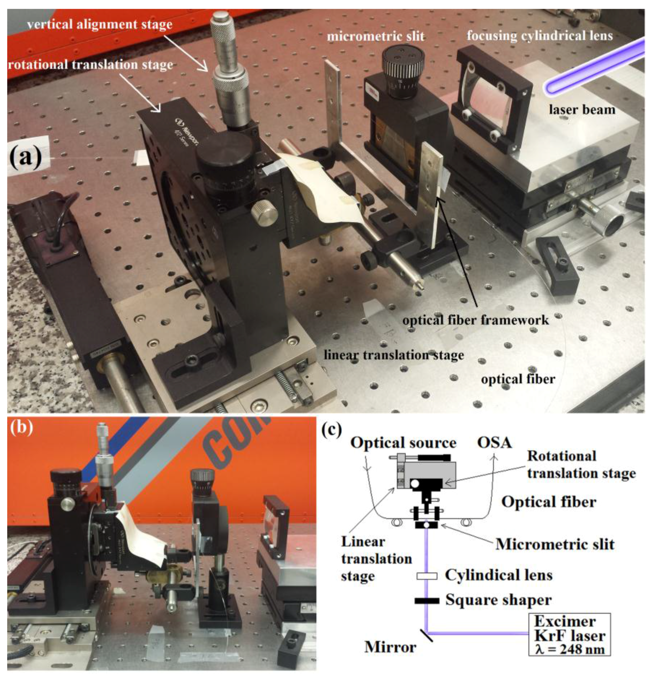
  • a focusing cylindrical lens (focal length 10 cm) placed at a horizontal distance of 85 mm with respect to the fiber, which allows the best focusing of the laser beam on the fiber;
  • a manual-adjusting micrometric slit that is set to half of the chosen grating period, Λ/2 (1 μm resolution; Micro-Controle, France);
  • a homemade framework that allows placing the optical fiber into U-grooves and keeping it straight;
  • a vertical (manual) translation stage that allows positioning the optical fiber at the same height of the laser beam (0.5 μm resolution; differential micrometer DM-13 mounted on a Newport 460A-XYZ series translation stage) (Newport Corporation, Irvine, CA 92606, USA);
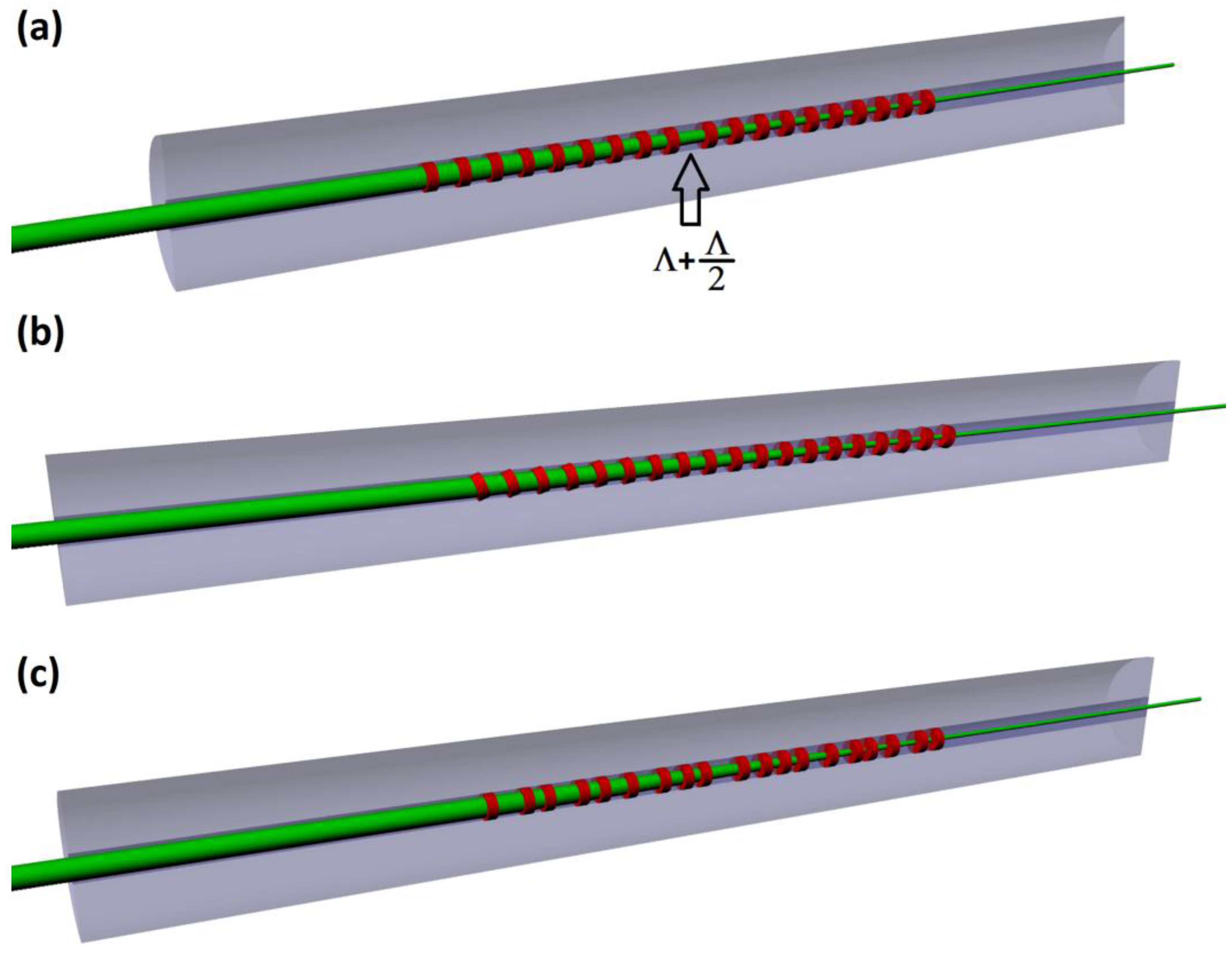
  • a rotational (manual) translation stage that allows the manufacturing of tilted grating planes as in Figure 2a (0.01° resolution; precision rotation stage, Newport 472 series); and
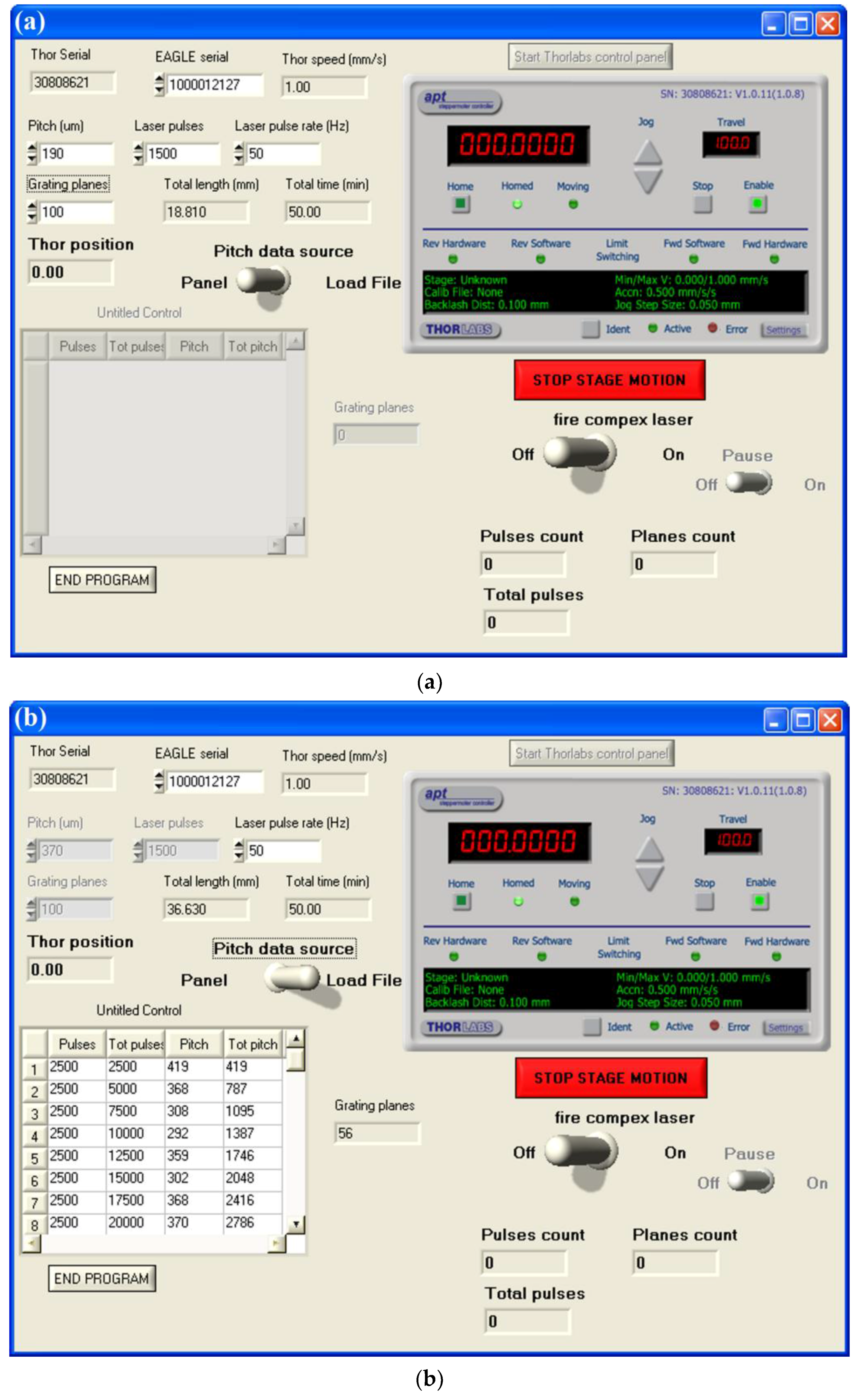
  • a linear PC-controlled translation stage that allows the horizontal movement of the optical fiber according to the chosen grating period (0.1 μm resolution and 0.3 μm bidirectional repeatability; an LNR 50 series stepper motor driver controlled by an APT stepper motor controller, Thorlabs BSC001, Thorlabs Inc., Newton, NJ, USA).
Figure 3b,c detail the lateral view and a top-view sketch of the experimental setup, respectively, where the laser beam is fixed (in position) and the optical fiber mounted on the translation stages moves step-by-step.
The software part of the experimental setup consists both of a program developed in an ad-hoc manner by means of the NI LabWindows/CVI 2015 (National Instruments Corporation, Austin, TX, USA) environment and of a digital input/output board (Eagle μ-DAQUSB-96C) (Eagle Appliances (Pty) Ltd. T/A Eagle Technology, Zonnebloem, Cape Town 8001, South Africa). In this way, the PC controls and synchronizes both the linear translation stage and the laser action. If any tilt should be realized in the grating, after the correct alignment of the optical fiber with respect to the laser beam using the vertical translation stage, the above-mentioned program manages everything. Figure 4a shows the front panel of the software used to manufacture LPFGs with a fixed value of Λ, like standard LPFGs and turn-around point (TAP) gratings. For the sake of completeness, TAP LPFGs are a special class of standard gratings where, by decreasing the value of Λ down to 200 μm, the coupled cladding mode (high order) exhibits a dual-band feature in the transmission spectrum [32,33,34]. When those bands merge into a broader one, the TAP in the PMC of the mode is reached.
On the other hand, Figure 4b details the front panel of the software used to manufacture LPFGs with a variable value of Λ, like phase-shifted and internally-tilted gratings, and/or of laser pulses for each grating plane, like pseudo-random gratings. In the first case, a .txt file is loaded and contains all the information related to the different period, while the rotation in internally tilted LPFGs is manually induced step-by-step according the total tilt angle to realize [25]. In the second case, another .txt file is loaded and contains all the information related to both the period and the number of laser pulses for each grating plane as shown in Figure 4b. After inserting all the parameters or loading the correct file, the program provides the manufacturing time expressed in minutes and the grating inscription can be started turning on the switch named “fire compex laser.”
It is worth highlighting that the proposed experimental setup for grating inscription makes it possible to avoid any pre- and post-fabrication operation, such as the hydrogen loading of the fiber, grating annealing, etc. Moreover, it can also be used to manufacture FBGs in the same photosensitive fiber with the help of the phase-mask technique by slightly modifying the experimental setup [35].
Finally, in order to record the transmission spectra of the LPFGs, the measuring setup consists simply of a broadband light source, SLD-1310/1430/1550/1690-10 (FiberLabs Inc., Fujimino-shi, Saitama, 356-8502 Japan), with a wavelength range from 1250 nm up to 1750 nm, and an optical spectrum analyzer, Anritsu MS9030A and MS9701B (Anritsu Company, Atsugi-shi, Kanagawa 243-8555, Japan), with a wavelength range from 350 nm up to 1750 nm and with an optical resolution of 0.1 nm.

3. Results and Discussion

In this section, different kinds of LPFGs will be described in terms of both manufacturing parameters, such as grating period (Λ), number of grating planes (N), and number of laser shots (Nlas), and spectral features, such as resonance wavelength (λres), transmission depth (Tmax), spectral displacement (∆λ), and full width at half maximum (FWHM). As a general observation, by considering all the noise sources coming from the entire experimental setup and by manufacturing several LPFGs of different kinds, these spectral features that will be discussed in detail in the next section were evaluated in their repeatability: the resonance wavelength (±5 nm), the maximum transmission depth (±1 dB), and the bandwidth (±2 nm). In particular, the attention will be focused on phase-shifted LPFGs (Section 3.1), TAP LPFGs (Section 3.2), internally-tilted LPFGs (Section 3.3), and pseudo-random LPFGs (Section 3.4).

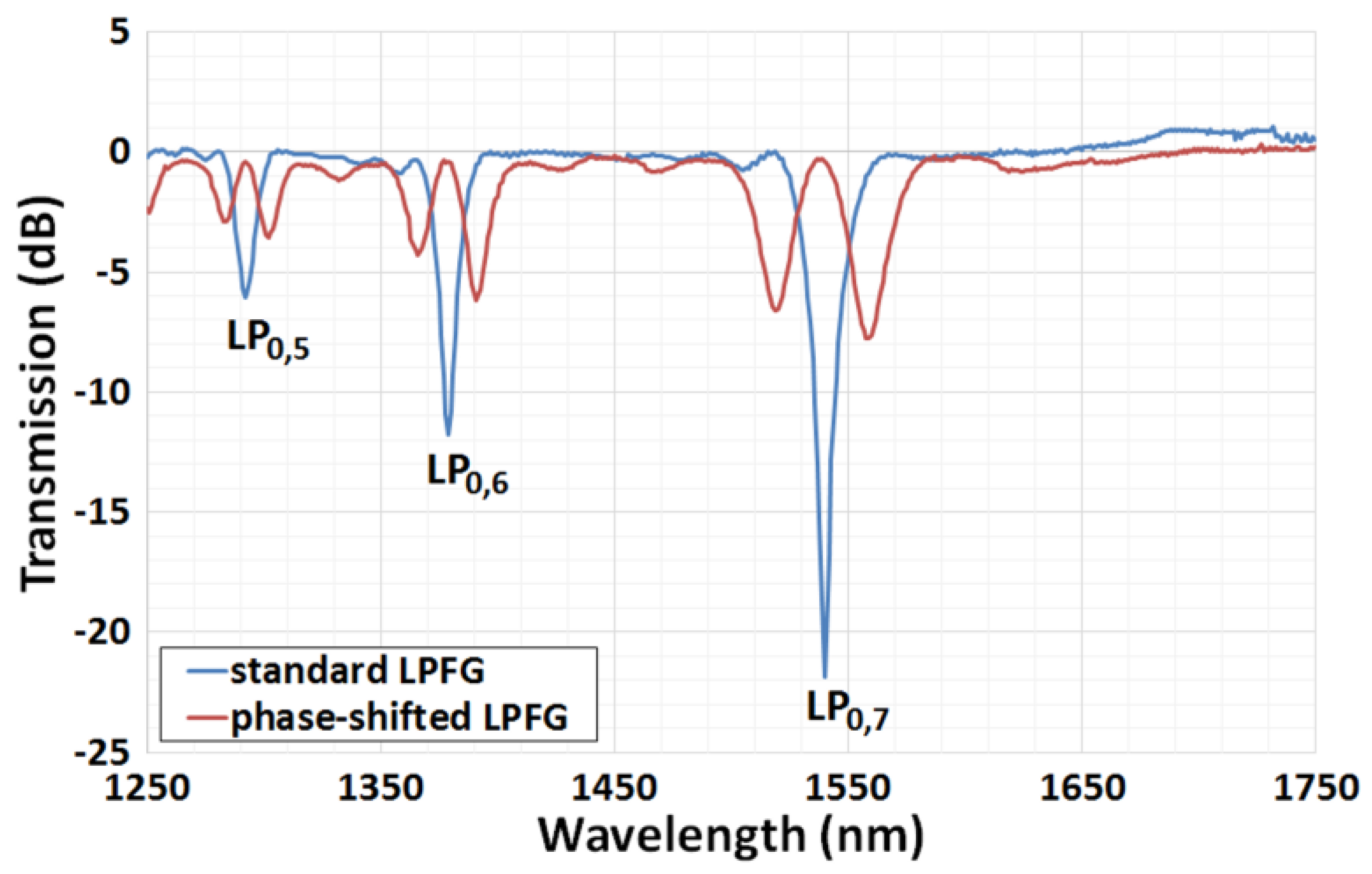
3.1. Phase-Shifted LPFGs

The phase-shifted configuration of grating planes (see Figure 2a) was formerly applied to FBGs [23,24]. Afterwards, the same structure was also applied to LPFGs [30,36]. This kind of grating found applications not only in telecommunications, as wavelength demultiplexing and optical filters, but also in sensing for the measurement of temperature and refractive index [37].
Here, an example of phase-shifted LPFGs was manufactured along with a standard one for comparison purposes, where the coupling within the spectral range of 1250 nm–1750 nm occurs at increasing wavelengths with the LP0,5, LP0,6 and LP0,7 (linearly polarized) cladding modes. Figure 5 shows the transmission spectra of those gratings: the standard LPFG (blue curve, Λ = 356 nm) and the phase-shifted one (red curve), where the period of the central grating plane that induces a π phase shift is 534 μm (3Λ/2; see Figure 2a). In fact, for each cladding mode, the two resonant bands of the phase-shifted configuration are placed exactly in between the original one. By focusing on the LP0,7 (higher) cladding mode, the spectral features are as follows: λres,left and λres,right equal to 1519 nm and 1559 nm, respectively (λres equal to 1540 nm for the standard LPFG), Tmax,left and Tmax,right equal to 6.6 dB and 7.8 dB, respectively (Tmax equal to 21.9 dB for the standard LPFG), and FWHMleft and FWHMright equal to 17 nm and 20 nm, respectively (FWHM equal to 9 nm for the standard LPFG). It is worth mentioning that, for the two gratings, the other general manufacturing parameters are the followings: Λ equal to 356 μm and N equal to 56 for both the phase-shifted and the standard LPFGs, and Nlas equal to 2000 and 2500 for the phase-shifted LPFG and for the standard LPFG, respectively. This difference in Nlas can easily explain the higher transmission depths of the attenuation bands in the standard LPFG.

3.2. Turn-Around Point LPFGs

TAP LPFGs are very interesting gratings because they exhibit a higher RI sensitivity with respect to standard LPFGs [17] and also the presence of a dual-band feature in the transmission spectrum allows a differential measurement of the minimum of the two bands (spectral displacement). For those reasons, TAP LPFGs found several applications especially in biosensing [32,38].
Four different TAP LPFGs were manufactured, where the coupling occurs always with the LP0,11 cladding mode. Figure 6 shows the transmission spectra of the four TAP LPFGs: from the grating at the TAP (blue curve) up to dual-band gratings with higher values of Tmax obtained by increasing the number of laser shots (red, grey, and violet curves). Table 1 collects both the manufacturing parameters and the most important spectral features of those gratings. Here, the critical point is to find the right combination of parameters (especially Λ and Nlas) to attain the requested spectral characteristics. For instance, the highest RI sensitivity is obtained when the single broad band tends to split into the narrower dual-band feature [17,32,39]. Moreover, in this case, the FWHM is smaller, thus, a higher resolution is expected [40,41]. This is clearly visible looking at the violet curve in Figure 6 and as detailed in Table 1.

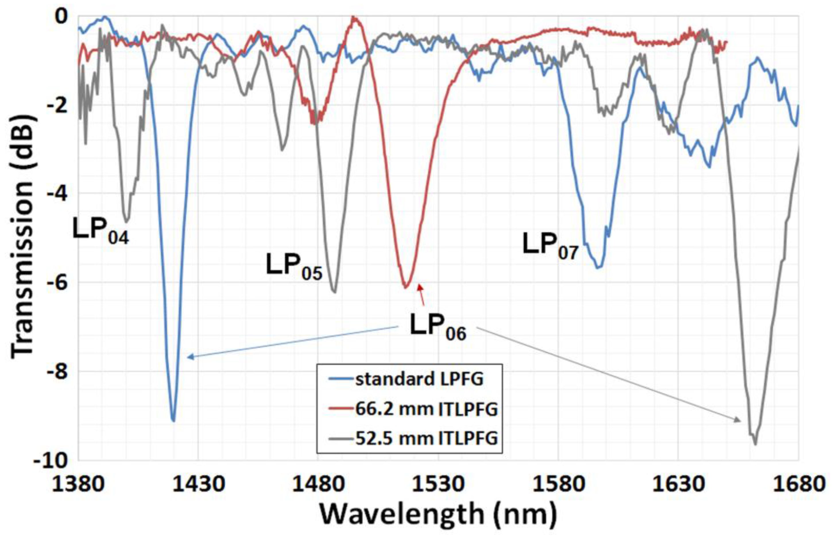
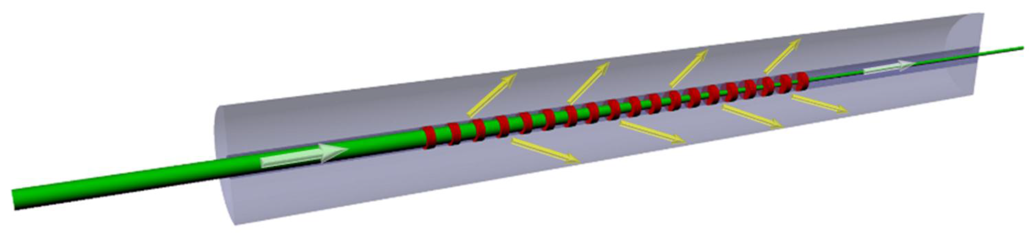
3.3. Internally-Tilted LPFGs

The third configuration of LPFGs that can be manufactured with the developed experimental setup described in the previous section is called internally tilted (see Figure 2b). The main advantage of this configuration is that the intrinsic RI sensitivity of each cladding mode increases, while the temperature sensitivity remains almost constant [25]. Moreover, this effect becomes larger when the realized inner curvature C (C = 1/R, R is the radius of curvature) of the grating planes increases as well (or R decreases) [25,26]. It was experimentally demonstrated that the previous effect follows a non-linear exponential behavior [26].
Two different internally-tilted LPFGs were manufactured, where the coupling occurs with the several cladding modes, from LP0,4 up to LP0,6. Figure 7 shows the transmission spectra of those LPFGs: from the standard LPFG (blue curve) up to internally tilted gratings with decreasing values of R (66.2 mm for the red curve and 52.5 mm for the grey curve). Table 2 collects both the manufacturing parameters and the most important spectral features of those gratings. Here, the critical point is to evaluate the feasibility of the grating in terms of R and the tilting angle θ: considering the procedure used to manufacture those device [25], there are some issues that could prevent the realization of low R or large θ. In addition, it is also known that the increase of the grating plane curvature shifts the resonance wavelength of each cladding mode toward longer wavelengths (see Table 2) [42]. For this reason and for comparing the spectral features of the same cladding mode, LP0,6 in this case, the period of the second internally tilted LPFG was decreased (330 μm) while N was increased (61), with respect to the first internally-tilted LPFG and to a standard LPFG (Λ = 370 μm and N = 55), in order to keep a comparable grating length.
Looking at Figure 7, it is apparent that novel nearside attenuation bands, probably not related to LP modes, came out with the realization of tilted grating planes. This phenomenon occurred in both the internally tilted LPFGs. The origin of those bands is still under investigation but it is clear that with the increase of the curvature (or the decrease of R) the attenuation band of each LP mode becomes broader with a larger FWHM (see Table 2). On the other hand, the value of the transmission depth is not directly influenced by the induced curvature, but depends mainly on the value of the coupling strength of the mode according to the manufacturing parameters of the grating, such as Λ and N [12].

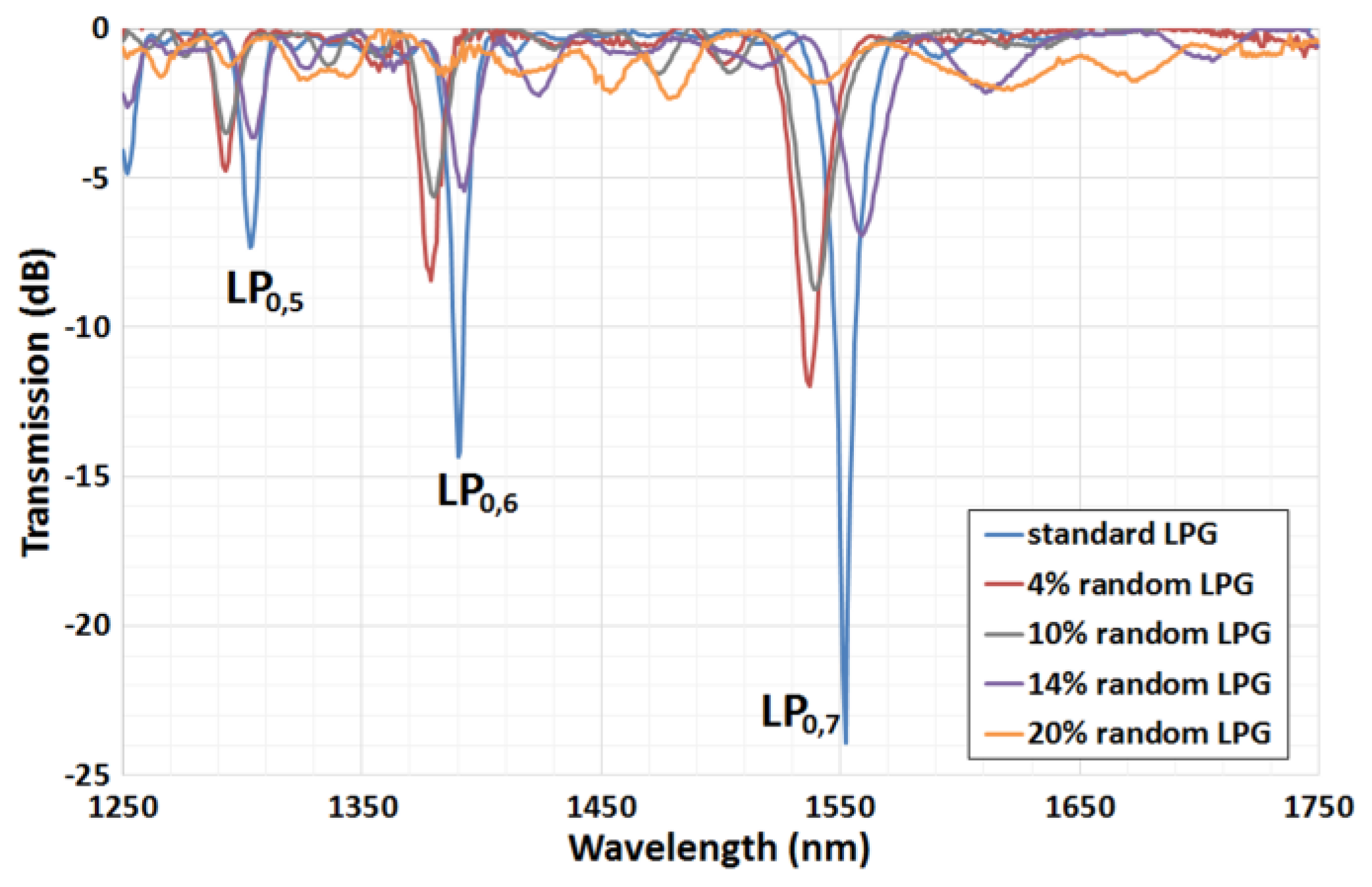
3.4. Pseudo-Random LPFGs

The last configuration of LPFGs that was manufactured with the proposed experimental setup is called pseudo-random (see Figure 2c). Given the novelty of this configuration applied to an LPFG, no sensing experiments have been performed yet, but the achieved spectral features suggest that this kind of grating could deserve to be examined in depth.
Four different pseudo-random LPFGs were manufactured, along with a standard one for comparison purposes, where the coupling within the spectral range of 1250–1750 nm occurs at increasing wavelengths with the LP0,5, LP0,6 and LP0,7 cladding modes. Figure 8 shows the transmission spectra of those gratings: from the standard LPFG (blue curve) up to pseudo-random gratings with increasing values of randomness δ (see Equation (2); red, grey, violet, and orange curves). Table 3 collects both the manufacturing parameters and the most important spectral features of the gratings related to the LP0,7 (higher) cladding mode only. It is worth mentioning that for all the gratings the other general manufacturing parameters are the followings: Λ of 355 μm ( Λ f i x e d ), N of 56 (thus, a total grating length of 19.88 mm) and Nlas of 2500. For the sake of completeness, the vector of δ was generated using the “RANDBETWEEN” function of Excel (Microsoft Office 2016): after establishing the desired randomness and providing the edging values in terms of maximum deviation with respect to the selected randomness, the function automatically creates the vector of randomness.
Looking at Figure 8, it is evident that, with the increase of the randomness, novel attenuation bands appear, probably not related to the LP modes. This effect became very strong in the case of the 20% pseudo-random LPFG (orange curve in Figure 8). The origin of those bands is still under investigation, but it is clear that with the increase of the randomness the attenuation band of each LP mode becomes broader with a lower transmission depth (see Table 3). Moreover, it should be pointed out that the random variations (δ) that were induced on purpose in the grating planes are surely greater than those due to the all the sources of randomness related to intrinsic manufacturing process, like laser power fluctuations, positioning errors, any “natural” random change in the grating period, etc. Finally, it is worth highlighting that any evidence of polarization effects was observed for this novel configuration of grating, with maximum variations of the λres and Tmax lower than 1 nm and 0.5 dB, respectively, by manually changing the injected polarization of light by means of a linear polarizer and a polarization controller.

4. Conclusions

The manufacturing and spectral features of different type of LPFGs, ranging from standard, phase-shifted, and internally-tilted gratings, to pseudo-random gratings, were described and discussed in detail. Thanks to the development of the proposed manufacturing setup, the total customization of the grating parameters allows the realization of several grating configurations and a combination of them can be easily obtained toward the development of novel grating structures, such as pseudo-random gratings. It is worth pointing out that any intrinsically photosensitive fiber, or a fiber made photosensitive by hydrogen loading, could be used to manufacture gratings with the proposed experimental setup, as, for instance, photonic crystal fibers or any other specialty optical fiber. Moreover, with the developed setup, the repeatability of some important spectral features was evaluated from the LPFGs’ spectra, such as the achieved resonance wavelength (±5 nm), the maximum transmission depth (±1 dB), and the full width at half maximum (±2 nm), considering all the noise sources coming from the entire experimental setup. In addition, these features were also taken into account in order to use them for different fiber-based applications, such as optical filtering, coupling systems, random lasers, physical and chemical sensing, and biosensing. For instance, in applications that require a multiplexing scheme for selective wavelength addressing, the control of the spectral features of the grating is crucial. With regard to the novel grating structure, i.e., pseudo-random LPFGs, since complex fiber optics ring structures recently exhibited a random lasing action [43], an interesting field of investigation is represented by the random laser linear topology. In this field, random LPFGs could play a very promising role as a new photonic structure. The present work can provide the basis for the development of novel grating configurations to be used in different fields, from physics to biochemistry.

Acknowledgments

The authors would like to acknowledge Simone Berneschi, Franco Cosi, Gualtiero Nunzi Conti, Ambra Giannetti, and Sara Tombelli from IFAC-CNR (Italy) for the insightful discussions and advice always provided.

Author Contributions

F.C. conceived the paper; F.C., C.T., and F.B. designed the experiments; C.T. designed and realized the gratings manufacturing software; F.C. performed the experiments; F.C. and C.T. analyzed the data; F.C. wrote the paper; and all the authors reviewed and edited the final paper.

Conflicts of Interest

The authors declare no conflict of interest. Moreover, the founding sponsors had no role in the design of the study; in the collection, analyses, or interpretation of data; in the writing of the manuscript, and in the decision to publish the results.

References

  1. Grattan, K.T.V.; Sun, T. Fiber optic sensor technology: An overview. Sens. Actuators A 2000, 82, 40–61. [Google Scholar] [CrossRef]
  2. Baldini, F.; Brenci, M.; Chiavaioli, F.; Giannetti, A.; Trono, C. Optical fibre gratings as tools for chemical and biochemical sensing. Anal. Bioanal. Chem. 2012, 402, 109–116. [Google Scholar] [CrossRef] [PubMed]
  3. Chiavaioli, F.; Baldini, F.; Tombelli, S.; Trono, C.; Giannetti, A. Biosensing with optical fibre gratings. Nanophotonics 2017, 6, 663–679. [Google Scholar] [CrossRef]
  4. Vaiano, P.; Carotenuto, B.; Pisco, M.; Ricciardi, A.; Quero, Q.; Consales, M.; Crescitelli, A.; Esposito, E.; Cusano, A. Lab on Fiber Technology for biological sensing applications. Laser Photonics Rev. 2016, 10, 922–961. [Google Scholar] [CrossRef]
  5. Vengsarkar, A.M.; Lemaire, P.J.; Judkins, J.B.; Bhatia, V.; Erdogan, T.; Sipe, J.E. Long-period fiber gratings as band-rejection filters. J. Lightwave Technol. 1996, 14, 58–65. [Google Scholar] [CrossRef]
  6. Wang, Z.; Ramachandran, S. Ultrasensitive long-period fiber gratings for broadband modulators and sensors. Opt. Lett. 2003, 28, 2458–2460. [Google Scholar] [CrossRef] [PubMed]
  7. Ashrafi, R.; Li, M.; Azaña, J. Coupling-strength-independent long-period grating designs for THz-bandwidth optical differentiators. IEEE Photonics J. 2013, 5, 7100311. [Google Scholar] [CrossRef]
  8. Farnesi, D.; Chiavaioli, F.; Righini, G.C.; Soria, S.; Trono, C.; Jorge, P.; Nunzi Conti, G. Long period grating-based fiber coupler to whispering gallery mode resonators. Opt. Lett. 2014, 39, 6525–6528. [Google Scholar] [CrossRef] [PubMed]
  9. Farnesi, D.; Chiavaioli, F.; Baldini, F.; Righini, G.C.; Soria, S.; Trono, C.; Nunzi Conti, G. Quasi-distributed and wavelength selective addressing of optical micro-resonators based on long period fiber gratings. Opt. Express 2015, 23, 21175–21180. [Google Scholar] [CrossRef] [PubMed]
  10. Gagné, M.; Kashyap, R. Random fiber Bragg grating Raman fiber laser. Opt. Lett. 2014, 39, 2755–2758. [Google Scholar] [CrossRef] [PubMed]
  11. Yin, H.; Gbadebo, A.; Turitsyna, E.G. Top-hat random fiber Bragg grating. Opt. Lett. 2015, 40, 3592–3594. [Google Scholar] [CrossRef] [PubMed]
  12. Kersey, A.D.; Davis, M.A.; Patrick, H.J.; LeBlanc, M.; Koo, K.; Askins, C.; Putnam, M.; Friebele, E.J. Fiber grating sensors. J. Lightwave Technol. 1997, 15, 1442–1463. [Google Scholar] [CrossRef]
  13. Bhatia, V.; Vengsarkar, A.M. Optical fiber long-period grating sensors. Opt. Lett. 1996, 21, 692–694. [Google Scholar] [CrossRef] [PubMed]
  14. Huang, Q.; Chen, H. Multi-parameter optochemical sensing based on coated cascaded long-period fiber gratings and frequency division multiplexing. Optik 2017, 132, 348–355. [Google Scholar] [CrossRef]
  15. Chiavaioli, F.; Biswas, P.; Trono, C.; Jana, S.; Bandyopadhyay, S.; Basumallick, N.; Giannetti, A.; Tombelli, S.; Bera, S.; Mallick, A.; et al. Sol-gel-based titania-silica thin film overlay for long period fiber grating-based biosensors. Anal. Chem. 2015, 87, 12024–12031. [Google Scholar] [CrossRef] [PubMed]
  16. Chiavaioli, F.; Trono, C.; Giannetti, A.; Brenci, M.; Baldini, F. Characterisation of a label-free biosensor based on long period grating. J. Biophotonics 2014, 7, 312–322. [Google Scholar] [CrossRef] [PubMed]
  17. Shu, X.; Zhang, L.; Bennion, I. Sensitivity characteristics of long-period fiber gratings. J. Lightwave Technol. 2002, 20, 255–266. [Google Scholar]
  18. Erdogan, T. Fiber grating spectra. J. Lightwave Technol. 1997, 15, 1277–1294. [Google Scholar] [CrossRef]
  19. Dong, X.; Zhang, H.; Liu, B.; Miao, Y. Tilted fiber Bragg gratings: Principle and sensing applications. Photonics Sens. 2011, 1, 6–30. [Google Scholar] [CrossRef]
  20. Guo, T.; Liu, F.; Guan, B.-O.; Albert, J. Tilted fiber grating mechanical and biochemical sensors. Opt. Laser Technol. 2016, 78, 19–33. [Google Scholar] [CrossRef]
  21. Liu, Y.; Zhang, L.; Bennion, I. Fabricating fibre edge filters with arbitrary spectral response based on tilted chirped grating structures. Meas. Sci. Technol. 1999, 10, L1–L3. [Google Scholar] [CrossRef]
  22. Chen, X.; Zhou, K.; Zhang, L.; Bennion, I. In-Fiber twist sensor based on a Fiber Bragg Grating with 81° tilted structure. IEEE Photonics Technol. Lett. 2006, 18, 2596–2598. [Google Scholar] [CrossRef]
  23. Agrawal, G.P.; Radic, S. Phase-shifted fiber Bragg gratings and their application for wavelength demultiplexing. IEEE Photonics Technol. Lett. 1994, 6, 995–997. [Google Scholar] [CrossRef]
  24. Liu, T.; Han, M. Analysis of π-Phase-Shifted Fiber Bragg Gratings for ultrasonic detection. IEEE Sens. J. 2012, 12, 2368–2373. [Google Scholar] [CrossRef]
  25. Chiavaioli, F.; Trono, C.; Baldini, F. Specially designed long period grating with internal geometric bending for enhanced refractive index sensitivity. Appl. Phys. Lett. 2013, 102, 231109. [Google Scholar] [CrossRef]
  26. Arjmand, M.; Chiavaioli, F.; Berneschi, S.; Baldini, F.; Soltanolkotabi, M.; Trono, C. Effect of induced inner curvature on refractive index sensitivity in internally tilted long-period gratings. Opt. Lett. 2016, 41, 1443–1446. [Google Scholar] [CrossRef] [PubMed]
  27. He, T.; Rishoj, L.; Demas, J.; Ramachandran, S. Dispersion compensation using chirped long period gratings. In Proceedings of the Conference on Lasers and Electro-Optics, San Jose, CA, USA, 5–10 June 2016. [Google Scholar]
  28. Verma, D.S.; Tripathi, S.M. Simultaneous measurement of temperature and strain using chirped long-period gratings. In Proceedings of the 13th International Conference on Fiber Optics and Photonics, Kanpur, India, 4–8 December 2016. [Google Scholar]
  29. Wong, R.Y.N.; Chehura, E.; James, S.W.; Tatam, R.P. A chirped long period grating sensor for monitoring flow direction and cure of a resin. In Proceedings of the Smart Sensor Phenomena, Technology, Networks, and Systems Integration 2013, San Diego, CA, USA, 10 March 2013. [Google Scholar]
  30. James, S.W.; Topliss, S.M.; Tatam, R.P. Properties of length-apodized phase-shifted LPGs operating at the phase matching turning point. J. Lightwave Technol. 2012, 30, 2203–2209. [Google Scholar] [CrossRef] [Green Version]
  31. Wong, R.Y.N.; Chehura, E.; Staines, S.E.; James, S.W.; Tatam, R.P. Fabrication of fiber optic long period gratings operating at the phase matching turning point using an ultraviolet laser. Appl. Opt. 2014, 53, 4669–4674. [Google Scholar] [CrossRef] [PubMed]
  32. Chiavaioli, F.; Biswas, P.; Trono, C.; Bandyopadhyay, S.; Giannetti, A.; Tombelli, S.; Basumallick, N.; Dasgupta, K.; Baldini, F. Towards sensitive label-free immunosensing by means of turn-around point long period fiber gratings. Biosens. Bioelectron. 2014, 60, 305–310. [Google Scholar] [CrossRef] [PubMed]
  33. Colaço, C.; Caldas, P.; Del Villar, I.; Chibante, R.; Rego, G. Arc-induced long-period fiber gratings in the dispersion turning points. IEEE J. Lightwwave Technol. 2016, 34, 4584–4590. [Google Scholar] [CrossRef]
  34. Szymańska, M.; Krogulski, K.; Mikulic, P.; Bock, W.J.; Śmietana, M. Sensitivity of long-period gratings modified by their bending. Proc. Eng. 2014, 87, 1180–1183. [Google Scholar] [CrossRef]
  35. Trono, C.; Baldini, F.; Brenci, M.; Chiavaioli, F.; Mugnaini, M. Flow cell for strain- and temperature-compensated refractive index measurements by means of cascaded optical fibre long period and Bragg gratings. Meas. Sci. Technol. 2011, 22, 075204. [Google Scholar] [CrossRef]
  36. Liu, Y.; Williams, J.A.R.; Zhang, L.; Bennion, I. Phase shifted and cascaded long-period fiber gratings. Opt. Commun. 1999, 164, 27–31. [Google Scholar] [CrossRef]
  37. Hishiki, K.; Li, H. Phase-shift formed in a long period fiber grating and its application to the measurements of temperature and refractive index. Opt. Express 2013, 21, 11901–11912. [Google Scholar] [CrossRef] [PubMed]
  38. Tripathi, S.M.; Bock, W.J.; Mikulic, P.; Chinnappan, R.; Ng, A.; Tolba, M.; Zourob, M. Long period grating based biosensor for the detection of Escherichia coli bacteria. Biosens. Bioelectron. 2012, 35, 308–312. [Google Scholar] [CrossRef] [PubMed]
  39. Biswas, P.; Basumallick, N.; Bandyopadhyay, S.; Dasgupta, K.; Ghosh, A.; Bandyopadhyay, S. Sensitivity enhancement of turn-around-point long period gratings by tuning initial coupling condition. IEEE Sens. J. 2015, 15, 1240–1245. [Google Scholar] [CrossRef]
  40. Chiavaioli, F.; Gouveia, C.A.J.; Jorge, P.A.S.; Baldini, F. Towards uniform metrological assessment of grating-based optical fiber sensors: From refractometers to biosensors. Biosensors 2017, 7, 32. [Google Scholar] [CrossRef] [PubMed]
  41. White, I.M.; Fan, X. On the performance quantification of resonant refractive index sensors. Opt. Express 2008, 16, 1020–1028. [Google Scholar] [CrossRef] [PubMed]
  42. Tsuda, H.; Urabe, K. Characterization of long-period grating refractive index sensors and their applications. Sensors 2009, 9, 4559–7145. [Google Scholar] [CrossRef] [PubMed]
  43. Lepri, S.; Trono, C.; Giacomelli, G. Complex active optical networks as a new laser concept. Phys. Rev. Lett. 2017, 118, 123901. [Google Scholar] [CrossRef] [PubMed]
Figure 1. 3D cross-section of a long period fiber grating and a sketch of the light coupling inside a single-mode fiber containing a standard LPFG. The induced refractive index modulation inside the fiber core allows the coupling with several cladding modes according to Equation (1), thus, a part of the light travels along the fiber cladding and is then missing from the fundamental core mode.
Fibers 05 00029 g001
Figure 2. (a) 3D cross-section of a phase-shifted LPFG where there is a kind of defect in the central grating plane equal to Λ + Λ/2 as highlighted by the black arrow; (b) a 3D cross-section of an internally-tilted LPFG where the grating planes are gradually tilted, moving from the symmetry center of the structure (central grating plane) toward both the edges of the grating; and (c) a 3D cross-section of a random LPFG where the period of the grating planes is not fixed, but changes within a selected value of randomness.
Fibers 05 00029 g002
Figure 3. (a) Picture of the experimental setup for the LPFG manufacturing consisting of a focusing cylindrical lens, a manual-adjusting micrometric slit, a homemade framework, and vertical, rotational, and linear translation stages; (b) a lateral view of the experimental setup; and (c) a sketch of the experimental setup.
Fibers 05 00029 g003
Figure 4. (a) Front panel of the ad-hoc-developed software (LabWindows/CVI) used to manufacture LPFGs with a fixed value of the grating period Λ (standard and TAP gratings); (b) front panel of the ad-hoc-developed software (LabWindows/CVI) used to manufacture LPFGs with a variable value of the grating period Λ (phase-shifted and internally-tilted gratings) and/or of laser pulses for each grating plane (random gratings).
Fibers 05 00029 g004
Figure 5. Fiber transmission spectra of a phase-shifted LPFGs (red curve) and of a standard grating with Λ = 356 μm (blue curve) for comparison. The coupling with different LP cladding modes ranging from LP0,5 up to LP0,7 occurs clearly. The length of the central defect equals to 534 μm (π-shifted).
Fibers 05 00029 g005
Figure 6. Fiber transmission spectra of four TAP LPFGs corresponding to different coupling conditions of the same LP0,11 cladding mode: grating at the TAP (blue curve), dual-band gratings with increasing transmission depths of 4 dB (red curve), 9 dB (grey curve), and 23 dB (violet curve) obtained by increasing the number of laser shots from 400, then 1000 up to 1500, respectively.
Fibers 05 00029 g006
Figure 7. Fiber transmission spectra of two internally-tilted LPFGs and a standard grating for comparison: standard LPFG (blue curve), 66.2 mm internally-tilted LPFG (red curve), and 52.5 mm internally-tilted LPFG (grey curve).
Fibers 05 00029 g007
Figure 8. Fiber transmission spectra of four pseudo-random LPFGs and a standard grating for comparison: standard LPFG (blue curve), 4% pseudo-random LPFG (red curve), 10% pseudo-random LPFG (grey curve), 14% pseudo-random LPFG (violet curve), and 20% pseudo-random LPFG (orange curve). The coupling with different LP cladding modes (from LP0,5 to LP0,7) and with other modes clearly occurs.
Fibers 05 00029 g008
Table 1. Manufacturing parameters and spectral features of four different TAP LPFGs corresponding to different coupling conditions of the same LP0,11 cladding mode.
Main CharacteristicsΛ (μm)NNlasλres (nm), LP0,11Tmax (dB)∆λ (nm)FWHM (nm)
TAP192100100015803.5-125
Dual-band1911004001430 (left), 1740 (right)431055
Dual-band19110010001468 (left), 1718 (right)925045
Dual-band19111215001525 (left), 1665 (right)2314021
Table 2. Manufacturing parameters and spectral features of two different internally-tilted LPFGs compared to a standard LPFG.
Main CharacteristicsΛ (μm)NNlasR (mm)θλres (nm), LP0,6Tmax (dB)FWHM (nm)
Standard37055700--14199.111
Internally tilted3705570066.217.3°15166.220
Internally tilted3306190052.521.6°16629.625
Table 3. Manufacturing parameters and spectral features of four different pseudo-random LPFGs compared to a standard LPFG.
Main Characteristicsδ (μm)δ (%)λres (nm), LP0,7Tmax (dB)FWHM (nm)
Standard--1552248
Pseudo-random154.215371214
Pseudo-random359.815408.816
Pseudo-random5014.11559718
Pseudo-random7019.71542225

