
Multi-Scale Carbon (Micro/Nano) Fiber Reinforcement of Polyetheretherketone Using High Shear Melt-Processing


Department of Materials Science and Engineering, Rutgers University, 607 Taylor Road, Piscataway, NJ 08854, USA
*
Author to whom correspondence should be addressed.
Fibers 2017, 5(3), 32; https://doi.org/10.3390/fib5030032
Submission received: 8 July 2017
/
Revised: 2 August 2017
/
Accepted: 17 August 2017
/
Published: 28 August 2017
(This article belongs to the Special Issue Fiber Reinforced Polymer Composites or Polymer-Carbon Nanotube Nanocomposites)
Abstract
:Fiber-reinforced polymer matrix composites offer lightweight, high mechanical performance but have required much effort to achieve good fiber–matrix adhesion and uniform distribution, and generally suffer from low impact resistance. In this work, a uniform, high shear melt-processing method was used to prepare carbon fiber (CF) reinforced polyetheretherketone (PEEK), carbon nanofiber (CNF) reinforced PEEK, and multi-scale CF and CNF reinforced PEEK composites. Scanning electron microscopy images show good fiber distribution and fiber–matrix interaction, as well as surface crystallization of PEEK from the fiber surfaces. Tensile modulus and strength increase most significantly with the addition of CF but with a loss in ductility. The multi-scale composite of CF–CNF-PEEK displays the stiffening effect from the CF and retains more ductility due to the CNF. Further, the CF–CNF-PEEK composite displays the highest impact energy absorption. This study shows that good mixing of CFs and CNFs is achievable in PEEK using a uniform, high shear processing method that can easily produce intricate shapes and provides a stiff, high impact energy absorption multi-scale carbon fiber-reinforced composite.
1. Introduction
Polymer matrix composites (PMCs) are widely used to obtain crucial functionality while replacing traditional, heavier materials. In particular, carbon-reinforced polymer matrix composites (C-PMCs), including carbon fiber (CF), carbon nanofiber (CNF), and carbon nanotubes (CNT), offer beneficial mechanical, thermal, and electrical properties to polymers. The highly specific properties of C-PMCs offer a lightweight alternative to traditional materials, such as wood, aluminum, and steel, in certain applications.
Carbon fiber is derived from polyacrylonitrile (PAN) or petroleum pitch. Typically, it is spun into a filament yarn to orient the polymer atoms, which is then taken through multiple heat treatments to oxidize, carbonize, and graphitize the filament [1]. The high temperature heat treatments produce filaments of very high modulus and high strength. Carbon fiber-reinforced polymer matrix composites (CF-PMCs), the most mature of the commercially available, lightweight alternative C-PMCs, allow load transfer between the strong, high modulus carbon fiber and the matrix but, as a result, suffer from brittleness [2,3]. Carbon nanofibers (CNF) are vapor-grown, resulting in cylindrical type nanostructures of graphene arranged as stacked cones. CNFs, due to their exceptional properties, have been used in carbon nanofiber-reinforced polymer matrix composites (CNF-PMCs) for a variety of applications for their mechanical, thermal and electrical properties [4,5,6]. CNF reinforcement of polymers does not tend to significantly increase modulus; however, toughness and fracture resistance are enhanced [7].
In order to enhance both modulus and toughness of polymers, multi-scale carbon micro/nano fiber composites have been developed and offer good mechanical properties [8], such as a 65% increase in tensile strength [9], 36% increase in tensile modulus [10], and 20% increase in fracture toughness [11], as compared to neat polymers. Multi-scale carbon micro/nano fiber reinforcement research has been predominantly limited to thermoset polymeric systems, typically epoxy systems, for which processing and part fabrication are limited or cost prohibitive for many applications. Thermoplastic polymers, however, offer more variability in processing and easy part fabrication, allowing the production of intricate geometry parts.
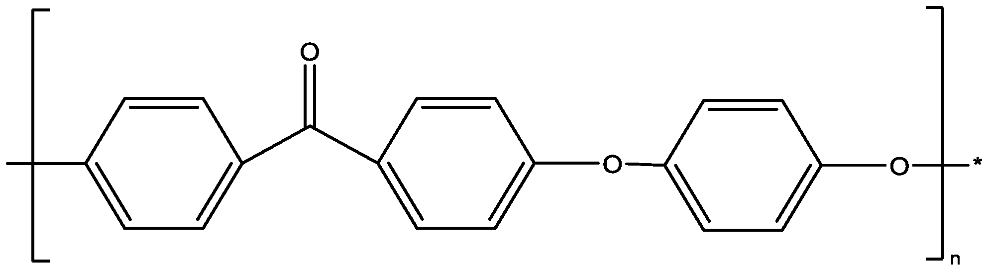
Polyetheretherketone (PEEK) is a high performance, semi-crystalline thermoplastic engineering polymer that maintains mechanical properties at high temperatures. PEEK is synthesized by the dialkylation of bisphenolate in step-growth polymerization [12], and the chemical structure is shown in Figure 1. Due to PEEK’s robust mechanical properties, chemical inertness and high temperature resistance, PEEK-based composites are used in a vast array of industries, including automotive, aerospace, chemical, and biomedical, with applications including flywheels, pumps, bearings, and implants. Carbon fiber reinforcement in PEEK provides a composite with enhanced mechanical properties [13,14], while the addition of nanoparticles to PEEK enhances friction and wear properties [15]. Further, CNF reinforcement of PEEK provides an increase in modulus to 5.5 GPa with the addition of 15 wt. % CNF [16]. To date, however, there is no reported use of multi-scale reinforcement of CF and CNF in PEEK. Multi-scale carbon-reinforced thermoplastic composites have been limited to growing CNFs on the CF surface prior to melt processing [17], in an attempt to reduce agglomeration. CNF agglomeration within the polymer matrix reduces the mechanical properties of the composite, specifically, lower strength, toughness and fracture resistance are reported. For example, it has been found that CNF agglomeration occurs at concentrations greater than 1 wt. % CNF in an epoxy, which reduced fracture toughness, fracture resistance, and strength [18]. It is suggested that CNF agglomeration impedes efficient stress transfer between CNF and the matrix, as well as, acting as stress concentration causing premature fracture [19]. For particle-matrix optimization, good dispersion followed by uniform distribution is required in order to enhance mechanical properties [20].
The aim of this study is to determine the effect of multi-scale reinforcement (CF and CNF) on PEEK using a novel, high shear melt-processing method [21]. Firstly, PEEK is reinforced with CF, secondly, PEEK is reinforced with CNF, and lastly, PEEK is reinforced with both CF and CNF. The composition dependence of the carbon reinforcement agents on PEEK is investigated and the morphology, tensile properties, impact resistance, and dynamic mechanical properties in torsion are presented.
2. Materials and Methods
2.1. Materials
Two types of carbon reinforcement, including carbon fiber (CF, Tenax-A HT C723, Toho Tenax America, Inc., Rockwood, TN, USA), and carbon nanofiber (CNF, PR-19-XT-LHT, Pyrograf Products Inc., Cedarville, OH, USA) were used for multi-scale reinforcement of polyetheretherketone (PEEK, KT-820NT, Solvay Specialty Polymers, Alpharetta, GA, USA). The CF is a general purpose, PAN-derived chopped fiber (length is 6 mm, diameter is 5 μm–7 μm) with a tensile modulus of 225 GPa and a tensile strength of 4275 MPa. The CNF is vapor-grown and produced via high temperature gas-phase molecule decomposition with carbon deposited in the presence of a transition metal catalyst on a substrate where the fiber grows. The LHT grade used in this work is heat treated at 1500 °C to carbonize chemically-vapor-deposited carbon present on the fiber surface and provides a short-range ordered structure. The CNF average fiber diameter is 150 nm and length is 50 µm–200 µm with a tensile modulus of 600 GPa and a tensile strength of 7000 MPa. This grade of PEEK has a low specific gravity of 1.32, high viscosity of 440 Pa-s, a glass transition temperature of 150 °C, melting temperature at 340 °C, tensile modulus of 3.5 GPa, and tensile strength of 95 MPa, as reported by the manufacturer.
2.2. Processing
Using a uniform, high shear injection molding method, PEEK was reinforced with CF, CNF and both CF and CNF [21]. Firstly, PEEK was reinforced with 0 wt. % CF, 5 wt. % CF, 10 wt. % CF, and 20 wt. % CF. Secondly, PEEK was reinforced with 0, 0.5, 1, 2, and 5 wt. % CNF. Thirdly, PEEK was reinforced with 20 wt. % CF and 2.5 wt. % CNF. The compositions are labeled as (wt. % reinforcement) (Reinforcing Agent)-PEEK, as shown in Table 1.
PEEK was dried at 160 °C for 6 h in a forced air convection oven, dry-blended with CF or CNF, and melt-processed using a V55-200 injection molding machine (Negri Bossi North America, Inc., New Castle, DE, USA) with a novel screw design that imparts uniform, high shear. When processing 20CF–2.5CNF-PEEK, segregation due to differing bulk densities is of great concern, thus a two-step process was used. Firstly, 20 wt. % CF and 80 wt. % PEEK were dry-blended in 100 gram batches and compounded using a Randcastle single screw extruder under a nitrogen blanket. Secondly, the pelletized extrudate was dried at 160 °C for 6 h and dry-blended with 2.5 wt. % CNF followed by injection molding using the same method previously described.
For all of the composite samples, components were injection molded under a nitrogen blanket at 100 RPM with processing temperatures for zones 1, 2, 3, and the nozzle at 362 °C, 362 °C, 362 °C, and 365 °C, respectively. Experimental testing was performed according to methods defined by American Society for Testing and Materials (ASTM). ASTM D638 Type 1 tensile and ASTM D256 impact specimens were produced with cross-sectional dimensions of approximately 3.2 mm by 12.5 mm. An experimental control of PEEK specimens was injection molded under the same processing conditions.
2.3. Characterization
Morphological characterization was performed using field emission scanning electron microscopy (SEM) of the prepared composites, including CF-PEEK, CNF-PEEK, CF–CNF-PEEK, and as received fibers, including CF and CNF. As received CF and CNF specimens were prepared by placing the fibers on adhesive carbon black tape mounted on an aluminum stud. CF-PEEK, CNF-PEEK, and CF–CNF-PEEK composite specimens were prepared by cryogenic fracture of injection molded specimens and fractured surfaces mounted on aluminum studs. To prevent charging of composite specimens, a 5 nm thick gold coating was sputtered on the fractured surface, and the sample placed under vacuum overnight prior to observation. A Sigma Field Emission SEM (Zeiss, Oberkochen, Germany) was used with both in-lens and secondary electron detectors to observe dispersion/distribution of the carbon reinforcement within PEEK and fiber–matrix interactions. Accelerating voltages of 5 keV and 10 keV were used to obtain optimum images.
Mechanical properties in tension and Izod impact resistance were characterized for CF-PEEK, CNF-PEEK, and CF–CNF-PEEK samples. All testing was conducted at room temperature (~23 °C), and test specimens were conditioned at 50% relative humidity for a minimum of 40 h after injection molding and prior to testing, according to ASTM standards. Tensile properties were determined using a QTest/25 Elite Controller Universal Testing System (MTS Systems Corp., Eden Prairie, MN, USA) with an extensometer mounted to the specimen, a 25 kN load cell, and a cross-head rate of 5 mm/min, according to ASTM D 638 “Standard Test Method for Tensile Properties of Plastics”. A minimum of 5 specimens per sample were tested to failure. The average results and standard deviation of each sample is reported, for statistical analysis, according to ASTM standards. A representative stress–strain curve is shown per sample, as well. Notched Izod impact properties were characterized using a Dynatup POE2000 Instrumented Pendulum Impact Tester (Instron Corporation, Norwood, MA, USA) at an impact velocity of 3.4 m/sec, according to ASTM D256 “Standard Test Methods for Determining the Izod Pendulum Impact Resistance of Plastics”. A minimum of 10 specimens per sample were tested, results averaged, and the standard deviation reported.
Dynamic mechanical testing was conducted in torsion using an AR 2000 Rheometer (TA Instruments, New Castle, DE, USA) for PEEK and 20CF–2.5 CNF-PEEK samples. The temperature ramp was performed over a temperature range of 25 °C–225 °C at a rate of 5 °C/min and a frequency of 1 Hz. Prior to the temperature ramp tests, the linear viscoelastic region was determined for each sample and the % strain selected from this region. The % strain for each temperature ramp was 0.016% and 0.011% for PEEK and 20 CF–2.5 CNF-PEEK, respectively.
3. Results and Discussion
3.1. Morphology
3.1.1. CF-PEEK
SEM micrographs of CF and CF-PEEK are shown in Figure 2. Microscopy of the carbon fiber surface (Figure 2a) displays a few surface disconformities in the form of particles, likely dust, with individual fibers bundled together with a 5 µm–7 µm diameter and 6 mm length, matching the manufacturer’s specifications. At low magnification of CF-PEEK (Figure 2b), there is an abundance of evenly separated carbon fibers in PEEK, showing good particle dispersion and distribution in the matrix. Upon close inspection, PEEK is seen wrapped around the CF, indicating very strong fiber–matrix adhesion, as shown by the arrow in Figure 2c. Similarly, strong fiber–matrix adhesion is seen along the CF length, with PEEK remaining on the CF surface even after cryogenic fracture, as indicated by the arrow in Figure 2d. Along the length of the fiber, evidence of transcrystallinity, or surface crystallization of PEEK, is evident by the directional crystal growth from the carbon fiber, resulting in a preferred orientation (indicated in the enclosed region in Figure 3d). Surface crystallization is a well-studied occurrence in CF–PEEK composites with the highlighted region matching known transcrystallinity features [22]. In general, polymer surface cyrstallization on CF provides good adhesion between the high stiffness fiber and less stiff polymer, resulting in enhanced mechanical properties [23]. There is evidence of some fiber pullout, as evident by black holes in Figure 2b, which most likely occurred when the main length of the well-adhered CF resided in the opposing fracture surface.
3.1.2. CNF-PEEK
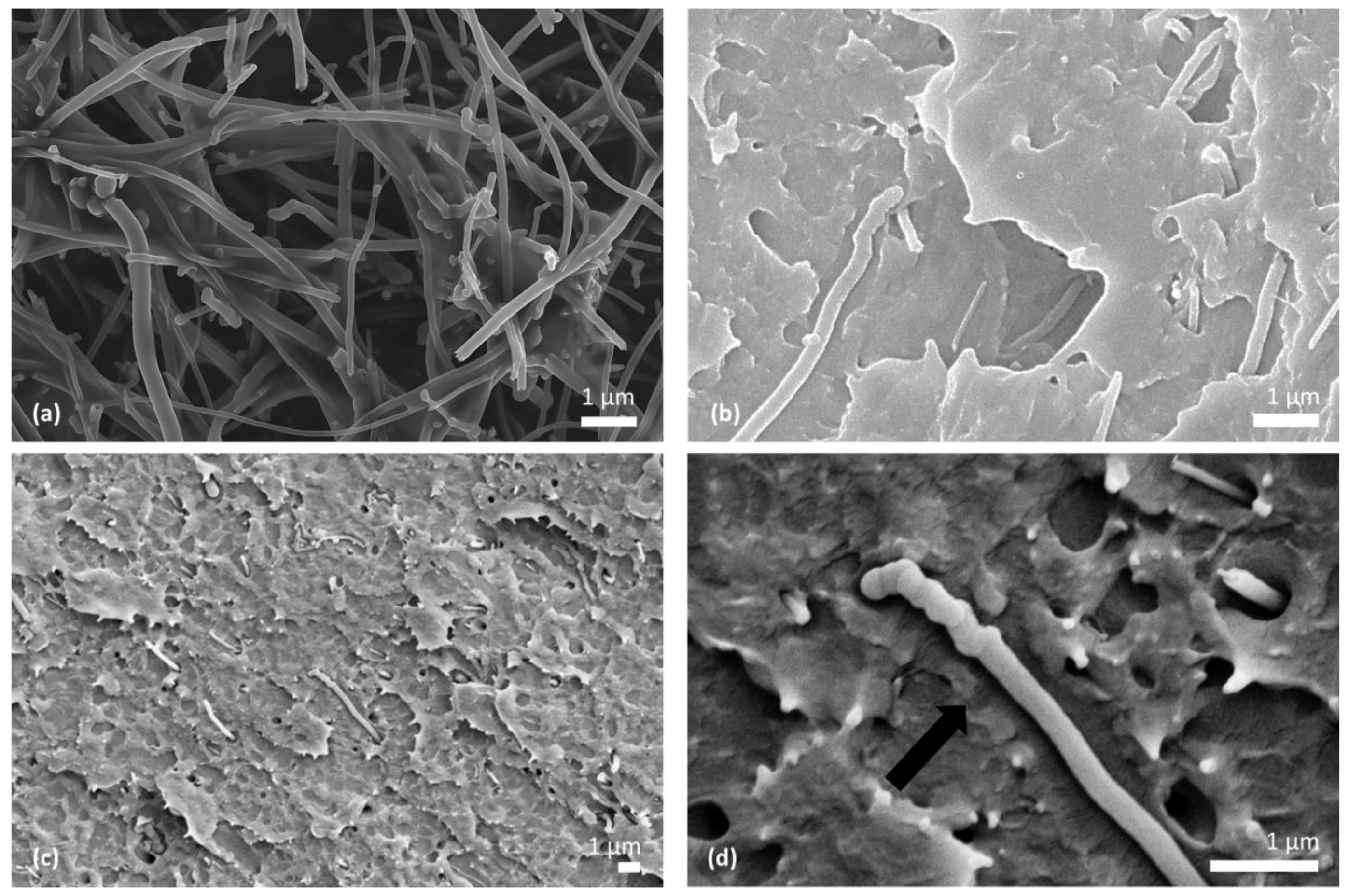
SEM micrographs of CNF and CNF-PEEK are shown in Figure 3. The morphology of the CNFs matches the manufacturer’s specifications and displays a diameter of 100 nm–200 nm and length up to 200 μm (Figure 3a). Good dispersion and distribution of CNF in PEEK at 2 and 5 wt. % CNF is evident in Figure 3b,c respectively. Transcrystallinity, similar to that observed within the CF-PEEK system, is visible perpendicular to the main CNF axis direction, as highlighted by the arrow in Figure 3d. Additionally, there are kinks visible on the CNF surface, which may act as a shape effect and impede fiber pullout.
3.1.3. 20CF–2.5CNF-PEEK, the Multi-Scale Composite
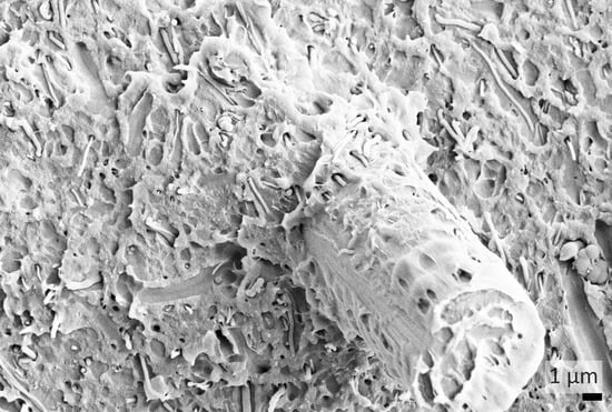
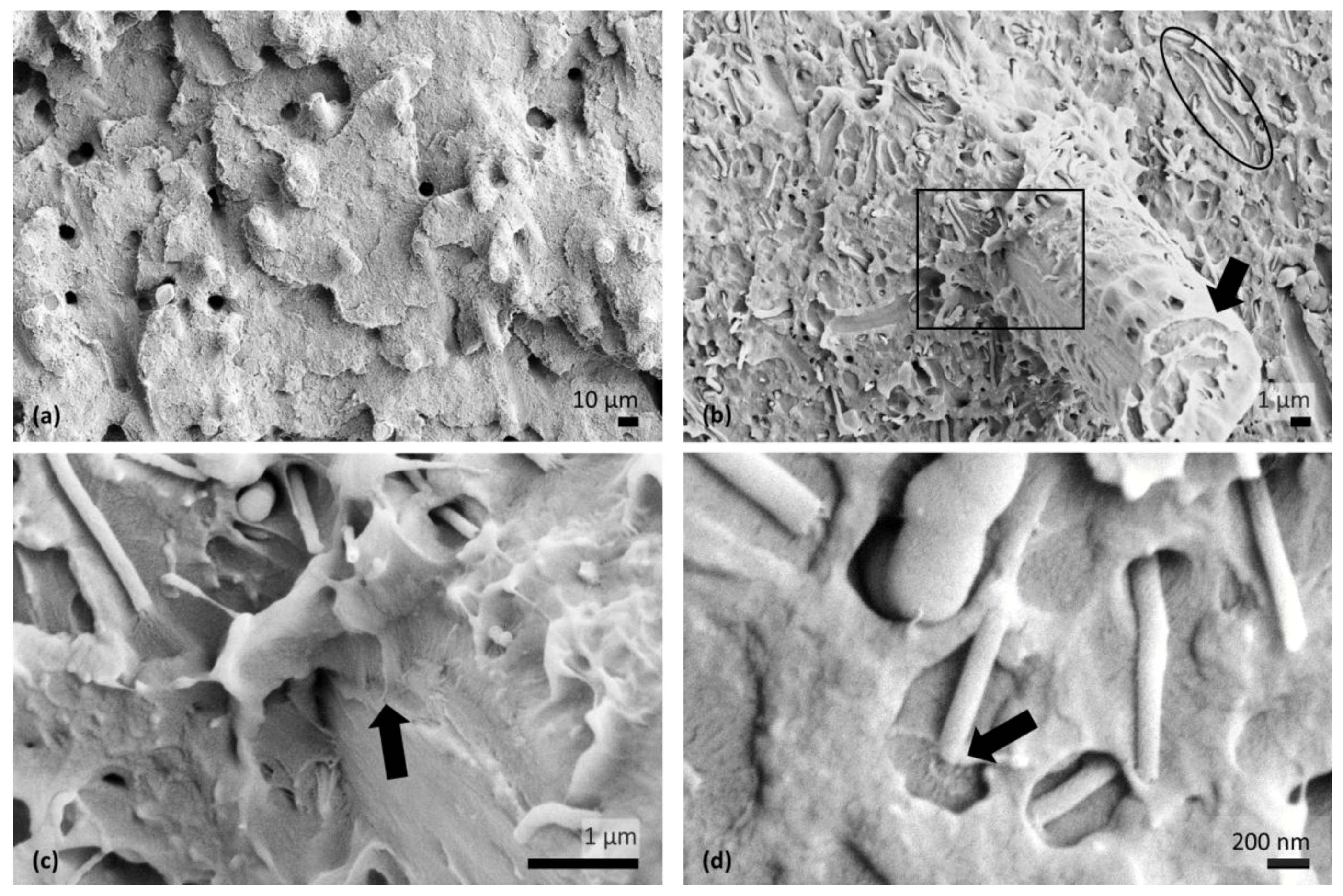
The morphology of the 20CF–2.5CNF-PEEK composite is shown in SEM micrographs in Figure 4. At low magnification (Figure 4a), there is an abundance of evenly separated CFs in PEEK, indicating good fiber dispersion and distribution. At higher magnification (Figure 4b), CF is well adhered and wetted along the fiber length and the ends, as indicated by the arrow. Near the base of the CF, the square region in Figure 4b is magnified and shown in Figure 4c, revealing well dispersed and distributed CNF in the PEEK matrix that is sprawled along the CF surface. Surface crystallization of PEEK in a preferred orientation is also observed throughout the structure, both surrounding the CF, as indicated by the arrow in Figure 4c, and along the length and ends of the CNF, as observed in the circled region in Figure 4b and the arrow in Figure 4d, respectively.
3.2. Tensile Results
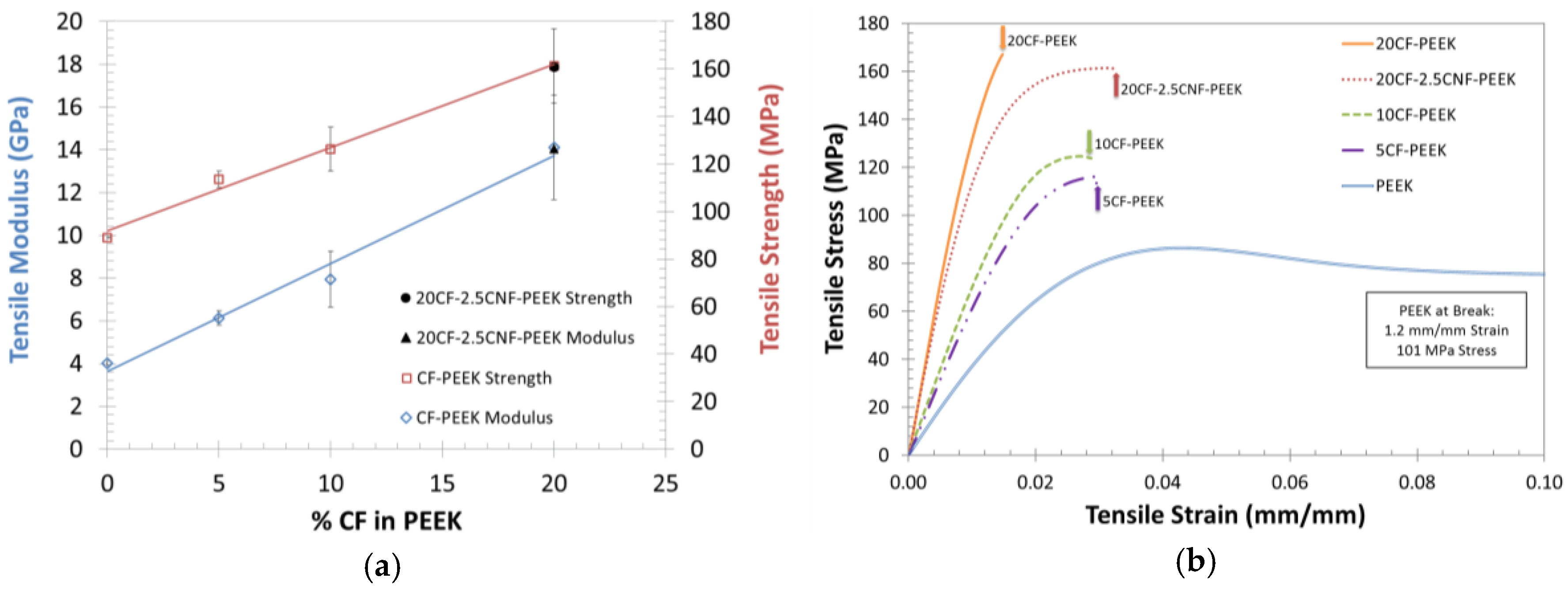
The tensile mechanical properties of the CF-PEEK and 20CF–2.5CNF-PEEK composites, along with the corresponding representative tensile stress–strain curves, are shown in Figure 5. With the addition of CF to the PEEK, the average tensile modulus and tensile strength increase linearly; however, % strain at fracture decreases, which is typical for fiber-reinforced PMCs. Notably, polymers produced using this uniform, high shear injection molding method attain significantly higher % strain at fracture than quoted by the manufacturer [21]. In this case, PEEK has a % strain at fracture of 120%, while the manufacturer simply states >50%. For 20CF-PEEK, tensile modulus and strength increase to 14.1 GPa ± 2.4 GPa and 161 MPa ± 15.5 MPa, respectively, matching the average tensile modulus, 14.3 GPa ± 0.6 GPa, and tensile strength, 161 MPa ± 2 MPa, of 20CF–2.5CNF-PEEK. Interestingly, addition of 2.5 wt. % CNF to 20CF-PEEK enhances ductility, while maintaining similar modulus and strength values as 20CF-PEEK, as seen in Figure 5b. This is likely due to CNFs acting as bridges throughout the matrix, thereby increasing the composite’s shear rigidity and improving the load transfer at higher strains [24].
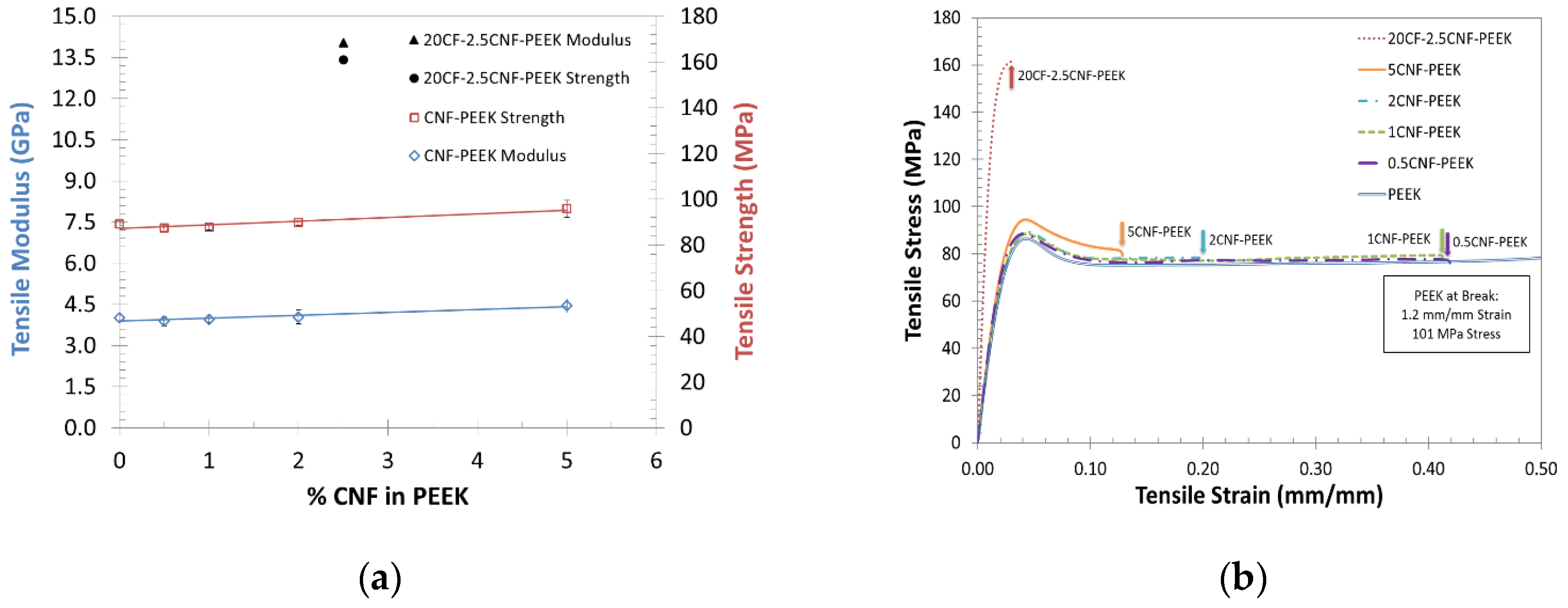
The tensile mechanical properties of the CNF-PEEK and 20CF–2.5CNF-PEEK composites, along with the corresponding representative stress–strain curves, are found in Figure 6. The addition of CNF to PEEK resulted in a slight linear increase to the average tensile modulus and tensile strength from that of neat PEEK. For 5CNF-PEEK, tensile modulus and strength increase to 4.45 GPa ± 0.25 GPa and 96 MPa ± 3.7 MPa, respectively, showing agreement with reported values [16]. All concentrations of the CNF-PEEK composites are more ductile than 20CF–2.5CNF-PEEK, as shown in Figure 6b. This supports the observation that CNFs likely act as bridges throughout the matrix due to good interfacial bonding between the fibers and the matrix, as well as kinks on the CNF surface impeding fiber pullout, and that CFs provide the main load bearing capability [24].
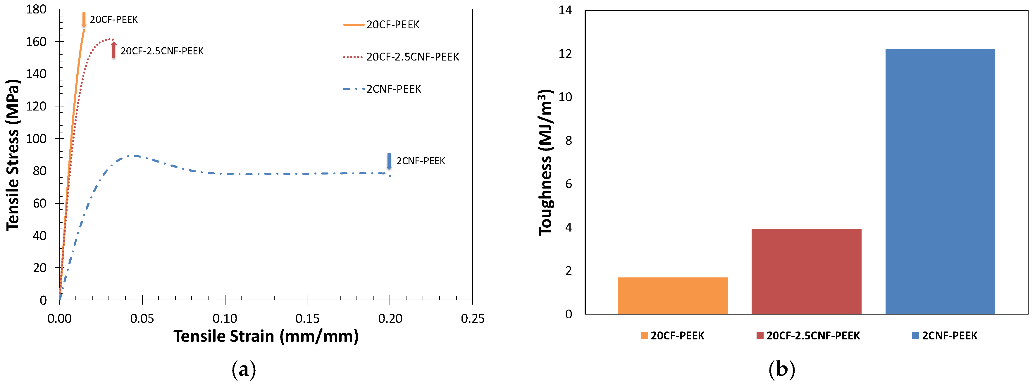
The 20CF–2.5CNF-PEEK multi-scale composite combines the stiffening, reinforcing effect of the CF and the enhanced ductility effect of the CNF, as shown in the stress–strain curves in Figure 7a. The most ductile composite in Figure 7a is 2CNF-PEEK, fracturing at 20% strain; however, tensile modulus and strength are the lowest. With the same CF concentration, 20CF-PEEK and 20CF–2.5CNF-PEEK have similar high values for tensile modulus and strength; however, addition of 2.5 wt. % CNF to 20CF-PEEK regains some of the lost ductility, or toughness. Toughness is measured by the area under the stress–strain curve, which is known to decrease with the addition of fibers to a polymer matrix. Remarkably, the addition of 2.5 wt. % CNF to 20CF-PEEK increases toughness (Figure 7b).
In general, CF and CNF reinforcement of PEEK using this novel injection molding method enhances mechanical properties; however, ideal fiber reinforcement in composites is not practically attainable. At best, law of mixtures performance is targeted when fabricating composites [25]. Ideal fiber reinforcement efficiency depends on fiber chemistry; fiber length, diameter, and cross-sectional geometry [26]; fiber surface chemistry and topography [4]; and fiber geometrical and spatial characteristics within the composite, including concentration, distribution, orientation, and the presence of voids or other processing side effects [25,27]. More specifically, there has been much effort in optimizing surface, or interfacial, fiber–matrix chemistry to attain better adhesion and subsequently enhanced performance. Ideal fiber reinforcement efficiency will always be limited by fiber–matrix interaction.
3.3. Impact Resistance Results
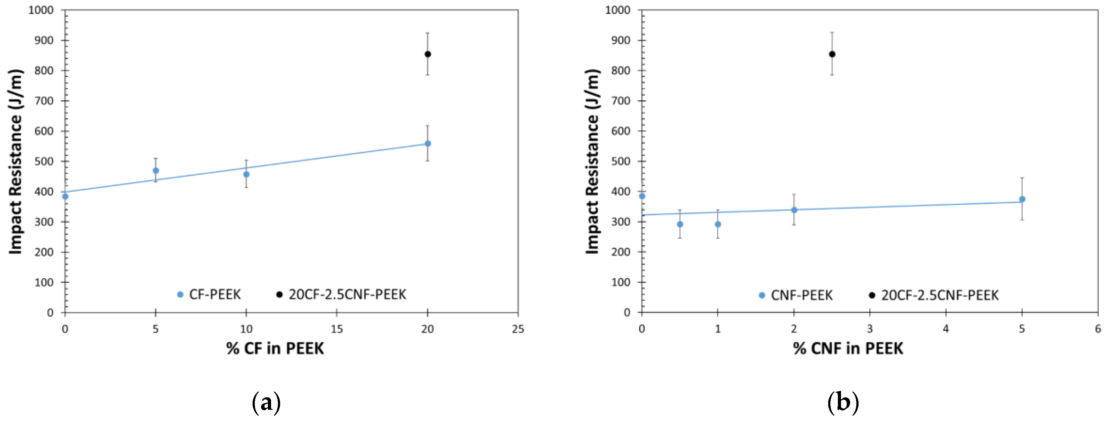
Average Izod impact resistance is shown in Figure 8 for the CF-PEEK, CNF-PEEK, and 20CF–2.5CNF-PEEK composites. All specimens in the composite samples underwent complete fracture, while all PEEK specimens underwent a hinge fracture type. Notably, the impact resistance of 20CF–2.5CNF-PEEK is vastly higher, 855 J/m ± 70 J/m, than that of any concentration of CF-PEEK and CNF–PEEK. Multi-scale CF–CNF reinforcement of PEEK provides a synergistic effect, and we suggest this is due to (1) intimate fiber–matrix interaction and (2) CNFs that are well-dispersed and distributed within 20CF-PEEK, providing a bridging effect and more tortuous path for crack propagation.
3.4. Dynamic Mechanical Torsion Results
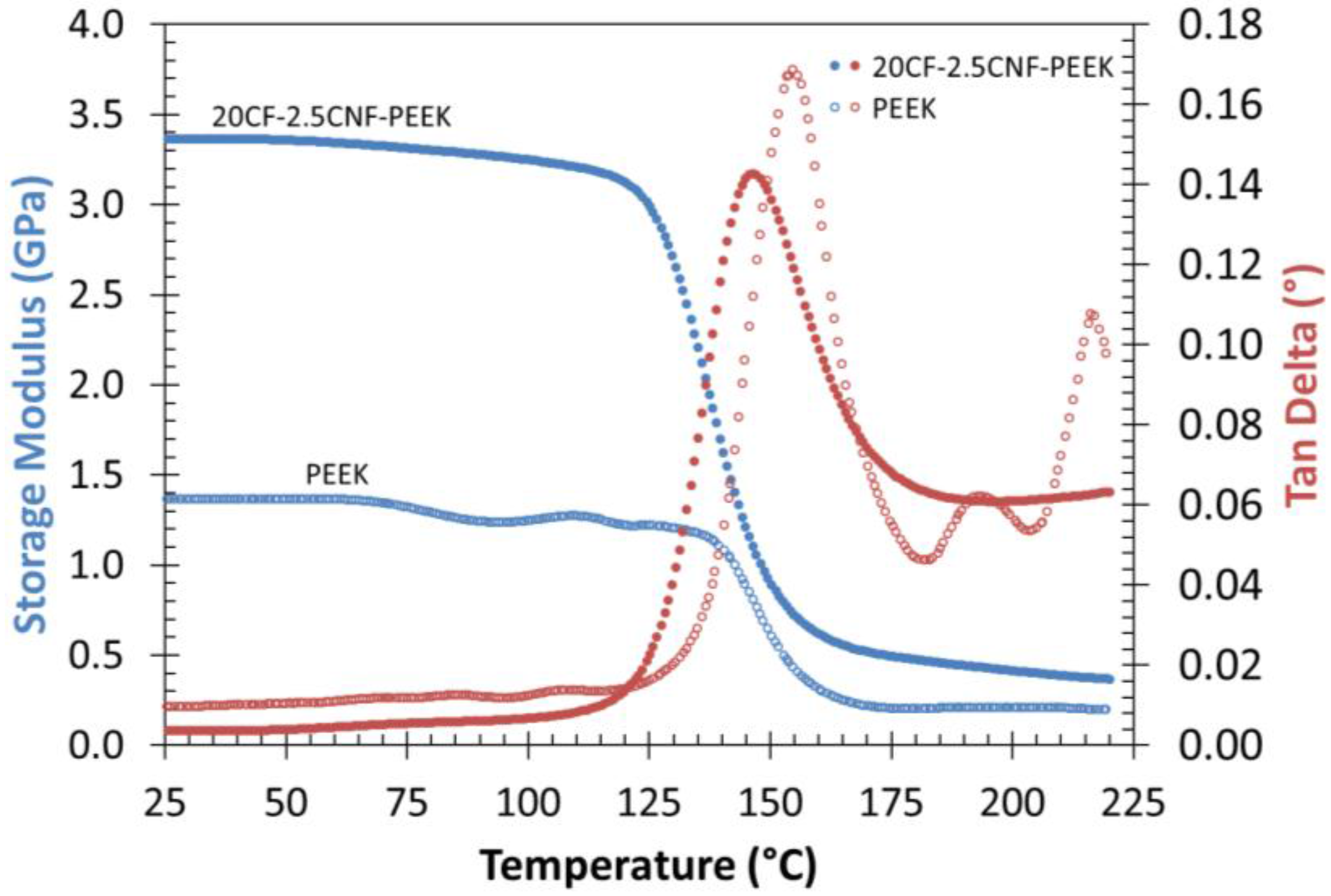
Dynamic mechanical torsion results for PEEK and 20CF–2.5CNF-PEEK are shown in Figure 9. Storage modulus increases with multi-scale CF and CNF reinforcement of PEEK before and after the glass transition temperature, Tg. The Tg is measured as 154 °C for PEEK and 146 °C for 20CF–2.5CNF-PEEK, as indicated by the peak maximum of the tan delta curves. This slight decrease in Tg is indicative of molecular motion occurring at a lower temperature in 20CF–2.5CNF-PEEK, since bulk crystallization may have been inhibited due to the large CF and CNF weight concentrations in the matrix.
4. Conclusions
In summary, a uniform, high shear melt-processing method was used to produce well-mixed nanocomposites of CF in PEEK, CNF in PEEK, and a multi-scale composite of 20 wt. % CF and 2.5 wt. % CNF in PEEK. SEM observations indicate that CF and CNF were well mixed (dispersed and distributed), separately and together within PEEK, resulting in intimate fiber–matrix interaction and surface crystallization of PEEK from the CF and CNF surfaces and ends.
Tensile modulus and ultimate tensile strength are greatly enhanced with the addition of CF to PEEK. For 20CF-PEEK, tensile modulus and strength increased by 350% and 160%, respectively, in comparison with PEEK; however, strain at break decreased significantly, as is typical with fiber-reinforced composites. On the other hand, CNF-PEEK composites exhibit only a slight increase in tensile modulus and strength but retain much more ductility.
The multi-scale-reinforced composite of 20CF–2.5CNF-PEEK combines both effects and exhibits high modulus and strength, similar to 20CF-PEEK, but with increased ductility due to the CNF reinforcement. Further, the 20CF–2.5CNF-PEEK multi-scale composite has the highest Izod impact resistance, as compared with CF-PEEK, CNF-PEEK, and PEEK, indicating the highest resistance to crack propagation and highest impact energy absorption capability. In essence, multi-scale carbon reinforcement of PEEK, using high shear processing, provides a superior composite to traditional fiber-reinforced composites.
Acknowledgments
This work was funded by the Center for Advanced Materials via Immiscible Polymer Processing (AMIPP) at Rutgers University and the Aresty Research Center at Rutgers University.
Author Contributions
The experiments were conceived and designed by Jennifer Lynch-Branzoi and Thomas Nosker. Justin Hendrix, Jennifer Lynch-Branzoi, Thomas Nosker and Arya Tewatia processed the materials. Justin Hendrix and Arya Tewatia performed mechanical property experiments and SEM analysis. Arya Tewatia and Jennifer Lynch-Branzoi analyzed the data. The manuscript was written and edited by Arya Tewatia and Jennifer Lynch-Branzoi, respectively.
Conflicts of Interest
The authors declare there are no conflicts of interest.
References
- Chung, D.D.L. Processing of Carbon Fibers. In Carbon Fiber Composites; Elsevier: Amsterdam, The Netherlands, 1994; pp. 13–53. [Google Scholar]
- Kim, J.-K.; Mai, Y.-W.; Mai, Y.-W. Interface mechanics and fracture toughness theories. In Engineered Interfaces in Fiber Reinforced Composites; Elsevier: Amsterdam, The Netherlands, 1998; pp. 239–277. [Google Scholar]
- Zhu, L. Investigations on damage resistance of carbon fiber composite panels toughened using veils. Chin. J. Aeronaut. 2013, 26, 807–813. [Google Scholar] [CrossRef]
- Poveda, R.L.; Gupta, N. Carbon Nanofibers: Structure and Fabrication. In SpringerBriefs in Materials; Springer International Publishing: Cham, Switzerland, 2016; pp. 11–26. [Google Scholar]
- Feng, L.; Xie, N.; Zhong, J. Carbon nanofibers and their composites: A review of synthesizing, properties and applications. Materials 2014, 7, 3919–3945. [Google Scholar] [PubMed]
- Kumar, R. Manufacturing of High Performance Polymer Nanocomposites Containing Carbon Nanotubes And Carbon Nanofibers Using Ultrasound Assisted Extrusion Process. Ph.D. Thesis, The University of Akron, Akron, OH, USA, December 2010. [Google Scholar]
- Bortz, D.R.; Merino, C.; Martin-Gullon, I. Carbon nanofibers enhance the fracture toughness and fatigue performance of a structural epoxy system. Compos. Sci. Technol. 2011, 71, 31–38. [Google Scholar] [CrossRef]
- Koissin, V.; Bor, T.; Kotanjac, Ž.; Lefferts, L.; Warnet, L.; Akkerman, R. Carbon Nanofibers Grown on Large Woven Cloths: Morphology and Properties of Growth. J. Carbon Res. 2016, 2, 19. [Google Scholar] [CrossRef]
- Rana, S.; Alagirusamy, R.; Fangueiro, R.; Joshi, M. Effect of carbon nanofiber functionalization on the in-plane mechanical properties of carbon/epoxy multiscale composites. J. Appl. Polym. Sci. 2012, 125, 1951–1958. [Google Scholar] [CrossRef]
- Hu, N.; Li, Y.; Nakamura, T.; Katsumata, T.; Koshikawa, T.; Arai, M. Reinforcement effects of MWCNT and VGCF in bulk composites and interlayer of CFRP laminates. Compos. B 2012, 43, 3–9. [Google Scholar] [CrossRef]
- Arai, M.; Hirokawa, J.I.; Hanamura, Y.; Ito, H.; Hojo, M.; Quaresimin, M. Characteristic of mode i fatigue crack propagation of CFRP laminates toughened with CNF interlayer. Compos. B 2014, 65, 26–33. [Google Scholar] [CrossRef]
- Kurtz, S.M. Synthesis and Processing of PEEK for Surgical Implants; Elsevier: Amsterdam, The Netherlands, 2012. [Google Scholar]
- Bozarth, M.J.; Gillespie, J.W.; McCullough, R.L. Fiber orientation and its effect upon thermoelastic properties of short carbon fiber reinforced poly(etheretherketone) (PEEK). Polym. Compos. 1987, 8, 74–81. [Google Scholar] [CrossRef]
- Lee, Y.; Porter, S.R. Crystallization of Poly(etheretherketone) (PEEK) in Carbon Fiber Composites. Polym. Eng. Sci. 1986, 26, 633–639. [Google Scholar] [CrossRef]
- Paul, D.R.; Robeson, L.M. Polymer nanotechnology: Nanocomposites. Polymer 2008, 49, 3187–3204. [Google Scholar] [CrossRef]
- Sandler, J.; Werner, P.; Shaffer, M.S.P.; Demchuk, V.; Altstädt, V.; Windle, A.H. Carbon-nanofibre-reinforced poly(ether ether ketone) composites. Compos. A 2002, 33, 1033–1039. [Google Scholar] [CrossRef]
- Ghaemi, F.; Ahmadian, A.; Yunus, R.; Ismail, F.; Rahmanian, S. Effects of Thickness and Amount of Carbon Nanofiber Coated Carbon Fiber on Improving the Mechanical Properties of Nanocomposites. Nanomaterials 2016, 6, 6. [Google Scholar] [CrossRef] [PubMed]
- Palmeri, M.J.; Putz, K.W.; Ramanathan, T.; Brinson, L.C. Multi-scale reinforcement of CFRPs using carbon nanofibers. Compos. Sci. Technol. 2011, 71, 79–86. [Google Scholar] [CrossRef]
- Zhou, Y.; Pervin, F.; Jeelani, S.; Mallick, P.K. Improvement in mechanical properties of carbon fabric-epoxy composite using carbon nanofibers. J. Mater. Process. Technol. 2008, 198, 445–453. [Google Scholar] [CrossRef]
- Rostamiyan, Y.; Fereidoon, A.B.; Omrani, A.; Ganji, D.D. Preparation, modeling, and optimization of mechanical properties of Epoxy/HIPS/silica hybrid nanocomposite using combination of central composite design and genetic algorithm. Part 2. Studies on flexural, compression, and impact strength. Strength Mater. 2013, 45, 703–715. [Google Scholar] [CrossRef]
- Lynch, J.K. High shear melt-processing of fiberglass-reinforced poly(trimethylene) terephthalate composites. J. Appl. Polym. Sci. 2015, 132. [Google Scholar] [CrossRef]
- Ishida, H.; Bussi, P. Surface-Induced Crystallization in Ultrahigh-Modulus Polyethylene Fiber Reinforced Polyethylene Composites. Macromolecules 1991, 24, 3569–3577. [Google Scholar] [CrossRef]
- Ishida, H.; Bussi, P. Surface Induced Crystallization in Fiber Reinforced Semicrystalline Thermoplastic Composites; Defense Technical Information Center: Fort Belvoir, VA, USA, 1991. [Google Scholar]
- Vivet, A.; Leclerc, W.; Doudou, B.; Chen, J.; Poilâne, C. Improvement by Nanofibers of Load Transfer in Carbon Fiber Reinforced Composites. Fibers 2015, 3, 134–150. [Google Scholar] [CrossRef]
- Harris, B. Engineering Composite Materials; IOM: Geneva, Switzerland, 1999. [Google Scholar]
- Steinmann, W.; Saelhoff, A.-K. Essential Properties of Fibres for Composite Applications. In Fibrous and Textile Materials for Composite Applications; Springer: Singapore, 2016; pp. 39–73. [Google Scholar]
- Callister, W.D. Composites. In Materials Science and Engineering: An Introduction, 7th ed.; John Wiley & Sons: Chichester, UK, 2006; pp. 577–620. [Google Scholar]
Figure 1.
Chemical structure of Polyetheretherketone (PEEK).

Figure 2.
Morphology of (a) as received CF; (b) 5CF-PEEK at low magnification; (c) 20CF-PEEK at high magnification with the axial cross section of carbon fiber visible; and (d) 20CF-PEEK at high magnification with the longitudinal orientation of the fiber visible, via SEM.
Figure 2.
Morphology of (a) as received CF; (b) 5CF-PEEK at low magnification; (c) 20CF-PEEK at high magnification with the axial cross section of carbon fiber visible; and (d) 20CF-PEEK at high magnification with the longitudinal orientation of the fiber visible, via SEM.
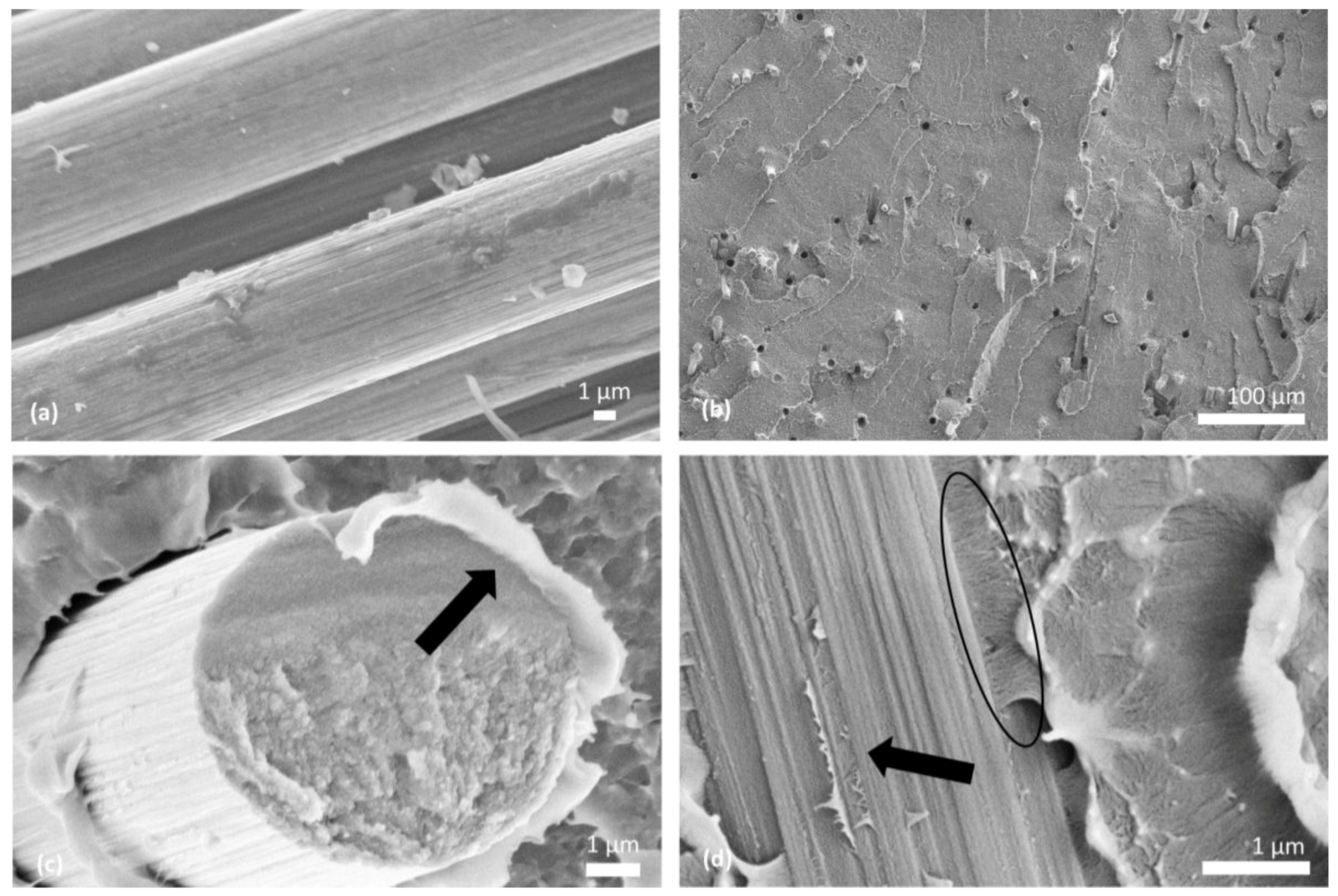
Figure 3.
SEM micrographs showing the morphology of (a) as received CNF; (b) 2CNF-PEEK; (c) 5CNF-PEEK at low magnification; (d) 5CNF-PEEK at high magnification via SEM.
Figure 3.
SEM micrographs showing the morphology of (a) as received CNF; (b) 2CNF-PEEK; (c) 5CNF-PEEK at low magnification; (d) 5CNF-PEEK at high magnification via SEM.

Figure 4.
SEM micrographs showing the morphology of 20CF–2.5CNF-PEEK (a) at low magnification; (b) at higher magnification with the axial carbon fiber visible; (c) at high magnification with the longitudinal orientation of the fiber visible; and (d) at high magnification.
Figure 4.
SEM micrographs showing the morphology of 20CF–2.5CNF-PEEK (a) at low magnification; (b) at higher magnification with the axial carbon fiber visible; (c) at high magnification with the longitudinal orientation of the fiber visible; and (d) at high magnification.

Figure 5.
Average tensile modulus and strength for varying wt. % CF in PEEK and the 20CF–2.5CNF-PEEK (a); and the corresponding representative stress–strain curve for those samples (b).
Figure 5.
Average tensile modulus and strength for varying wt. % CF in PEEK and the 20CF–2.5CNF-PEEK (a); and the corresponding representative stress–strain curve for those samples (b).

Figure 6.
Average tensile modulus and strength for wt. % CNF in PEEK and the 20CF–2.5CNF-PEEK (a); and the corresponding representative stress–strain curves for those samples (b).
Figure 6.
Average tensile modulus and strength for wt. % CNF in PEEK and the 20CF–2.5CNF-PEEK (a); and the corresponding representative stress–strain curves for those samples (b).

Figure 7.
Tensile results of 20CF-PEEK, 20CF–2.5CNF-PEEK, and 2CNF-PEEK (a) tensile stress–strain curves and (b) toughness.
Figure 7.
Tensile results of 20CF-PEEK, 20CF–2.5CNF-PEEK, and 2CNF-PEEK (a) tensile stress–strain curves and (b) toughness.

Figure 8.
Notched Izod impact resistance comparison for 20CF–2.5CNF-PEEK and (a) CF-PEEK and (b) CNF-PEEK.
Figure 8.
Notched Izod impact resistance comparison for 20CF–2.5CNF-PEEK and (a) CF-PEEK and (b) CNF-PEEK.

Figure 9.
Dynamic mechanical torsion comparison for PEEK and 20CF–2.5CNF-PEEK.

Table 1.
Carbon fiber (CF), carbon nanofiber (CNF), and CF–CNF-reinforced PEEK Composites Produced.
| wt. % CF | Label | wt. % CNF | Label | wt. % CF | wt. % CNF | Label |
|---|---|---|---|---|---|---|
| 0 | PEEK | 0 | PEEK | 0 | 0 | PEEK |
| 5 | 5CF-PEEK | 0.5 | 0.5CNF-PEEK | 20 | 2.5 | 20CF–2.5CNF-PEEK |
| 10 | 10CF-PEEK | 1 | 1CNF-PEEK | |||
| 20 | 20CF-PEEK | 2 | 2CNF-PEEK | |||
| 5 | 5CNF-PEEK |
© 2017 by the authors. Licensee MDPI, Basel, Switzerland. This article is an open access article distributed under the terms and conditions of the Creative Commons Attribution (CC BY) license (http://creativecommons.org/licenses/by/4.0/).
Share and Cite
MDPI and ACS Style
Tewatia, A.; Hendrix, J.; Nosker, T.; Lynch-Branzoi, J. Multi-Scale Carbon (Micro/Nano) Fiber Reinforcement of Polyetheretherketone Using High Shear Melt-Processing. Fibers 2017, 5, 32. https://doi.org/10.3390/fib5030032
AMA Style
Tewatia A, Hendrix J, Nosker T, Lynch-Branzoi J. Multi-Scale Carbon (Micro/Nano) Fiber Reinforcement of Polyetheretherketone Using High Shear Melt-Processing. Fibers. 2017; 5(3):32. https://doi.org/10.3390/fib5030032
Chicago/Turabian StyleTewatia, Arya, Justin Hendrix, Thomas Nosker, and Jennifer Lynch-Branzoi. 2017. "Multi-Scale Carbon (Micro/Nano) Fiber Reinforcement of Polyetheretherketone Using High Shear Melt-Processing" Fibers 5, no. 3: 32. https://doi.org/10.3390/fib5030032
Note that from the first issue of 2016, this journal uses article numbers instead of page numbers. See further details here.