
Polymer/Carbon Nanotubes (CNT) Nanocomposites Processing Using Additive Manufacturing (Three-Dimensional Printing) Technique: An Overview


Voith Paper Fabric & Roll Systems Inc. (Syn Strand Inc.—R&D), 215 Deming Way, Summerville, SC 29483, USA
Fibers 2017, 5(4), 40; https://doi.org/10.3390/fib5040040
Submission received: 3 August 2017
/
Revised: 8 September 2017
/
Accepted: 16 October 2017
/
Published: 23 October 2017
(This article belongs to the Special Issue Fiber Reinforced Polymer Composites or Polymer-Carbon Nanotube Nanocomposites)
Abstract
:Additive manufacturing (AM)/3D printing (3DP) is a revolutionary technology which has been around for more than two decades, although the potential of this technique was not fully explored until recently. Because of the expansion of this technology in recent years, new materials and additives are being searched for to meet the growing demand. 3DP allows accurate fabrication of complicated models, however, structural anisotropy caused by the 3DP approaches could limit robust application. A possible solution to the inferior properties of the 3DP based materials compared to that of conventionally manufactured counterparts could be the incorporation of nanoparticles, such as carbon nanotubes (CNT) which have demonstrated remarkable mechanical, electrical, and thermal properties. In this article we review some of the research, products, and challenges involved in 3DP technology. The importance of CNT dispersion in the matrix polymer is highlighted and the future outlook for the 3D printed polymer/CNT nanocomposites is presented.
1. Introduction
The additive-manufacturing (AM) technique through material extrusion, known as three-dimensional printing (3DP), has drawn remarkable attention from both academia and industry in recent years and this emerging field has been showing an exponential increase of the scientific interest. The technology of 3DP allows accurate fabrication of complicated sub-micron to few meters range structures from models by computer-aided design (CAD) or animation modeling software [1,2,3]. 3DP, which is widely regarded as a revolution in manufacturing technology, has been developed for a large range of applications, for example, in the field of aerospace and automotive [4], energy storage [5], electronics [6], engineered composites [7], biotechnology, tissue engineering [8], medical and pharmaceutical domains [9]. 3DP utilizes different techniques for the manufacturing of prototypes. Such techniques include Inkjet printing, Fused deposition modeling (FDM), Powder-bed technology, Micro-stereolithography (MSL), Dynamic optical projection stereolithography (DOPsL), Direct-write assembly (DW), selective laser sintering (SLS), Solvent-cast 3DP (SC-3DP), Conformal 3DP (C-3DP), Two-photon polymerization (TPP), and UV-3DP, among others [10,11,12,13].
There are numerous compatible materials available for 3DP, for example, metals, polymers, and ceramics [14,15,16]. Among these materials, polymers are in demand because of their diversified types, availability, processability, unique properties and price. Using 3DP technique objects could be fabricated by utilizing different polymeric materials such as latex, acrylonitrile-butadiene-styrene (ABS), poly(lactic acid) (PLA), poly(caprolactone) (PCL), polyamides, and photosensitive resins based on acrylic oligomer [17,18,19,20,21,22,23]. Moreover, combining polymer with nanoparticles such as carbon based nanofillers (carbon nanotubes (CNTs), graphene oxide (GO), carbon black, carbon nano-fibers), nanoclay and metallic nanofillers, it is possible to manufacture 3D materials with optimized target properties and multifunctionality beyond those of conventional pure printing materials, which enables a wide range of application [24,25,26].
The article of Iijima on CNTs in 1991 [27] was ground breaking in the field of materials science and soon after, researchers from different disciplines started to focus on this fascinating material. Since then, a tremendous amount of research work has been concentrated on the CNT incorporated advanced nanocomposites. CNTs are a long, thin cylinder of carbon with very high aspect ratio which possess outstanding tensile properties like tensile strength and modulus, and superior thermal and electrical conductivity [28,29,30,31,32,33,34]. CNTs, having the ability to induce the formation of highly ordered interphase polymer layer, can facilitate mechanical reinforcement by interfacial stress transfer between the nanotubes and polymer [35,36,37,38,39,40,41,42,43]. CNT, with a diameter comparable to the radius of gyration of the polymer chains, forces these chains to align parallel to the CNT axis upon crystallization. Thus, CNTs possess the ability to nucleate polymer crystal growth at the polymer/CNT interphase. This is due to the geometric confinement effect induced by the highly curved surface of CNTs [44,45]. The templating effect thus induced by the CNTs contributes toward the stress transfer mechanism of load between the polymer matrix and CNTs. Over the years, different routes have been developed for synthesizing verities of nanotubes like single-wall nanotubes (SWCNTs), double-wall nanotubes and multi-wall nanotubes (MWCNTs). Some prominent methods for the synthesis of CNTs include chemical vapor deposition (CVD), catalyst chemical vapor deposition (CCVD), arc discharge, and laser ablation [46,47,48,49,50,51,52,53,54,55,56,57,58]. However, after more than two decades of extensive research, the potential of CNTs as polymer reinforcement has not been fully utilized. Entanglement and bundling of CNTs, which arise because of the high aspect ratio and strong van der Waals interaction, prohibit their homogeneous dispersion in the polymer matrix [35,59,60,61,62]. Nevertheless, polymer/CNT nanocomposite processed by additive manufacturing has gained much attention in recent years and continuous efforts have been made to overcome these limitations.
In this review, the current progress on the processing of polymer/CNT nanocomposites for 3DP will be highlighted. The advantage and limitations of such nanocomposites as well as their future scopes for the 3DP techniques will be discussed.
A summary of all abbreviations used in this review is presented in Table 1.
2. Processing of Carbon CNT/Polymer Nanocomposites Using 3DP
Because of the outstanding properties of CNTs as mentioned before, initially they are a suitable candidate to integrate into 3D printing polymers. CNTs, with some structural defects, provide suitable nucleation sites which allow stronger interactions with polymers for crystallization [63,64,65,66]. Despite all these benefits, agglomeration of nanoparticles like CNTs can be detrimental to 3DP processing, especially for the methods like FDM, where blockages at the nozzle and flux instability can occur [67]. Better dispersion of the nanotubes along with the compatibility with the matrix polymer and optimization of their loading significantly improve the properties of nanocomposites [68] because of the magnificent properties of an individual CNT at well-dispersed condition which can be translated into the properties of a printed nanocomposite. In this section, a number of relevant studies has been discussed to follow the current trend and state-of-the-art 3D printed nanocomposites.
Sandoval et al. [69] carried out one of the preliminary studies on 3D printed polymer/CNT nanocomposites to understand the interfacial bonding between the commercially available epoxy-based SL resins and MWCNTs using the stereolithography (SL) layered manufacturing process. The dispersion of MWCNT in the epoxy resin was carried out by means of a few consecutive steps such as shear, non-localized ultrasonic dispersion and mechanical stirring via paddle. The dispersion was stable for a week which was attributed to the high viscosity of the SL epoxy resins. The highly viscus system overcomes the attractive forces between CNTs and delays the formation of CNT agglomerates, and thus, their precipitation. It was found that a MWCNT concentration of as low as 0.05% (w/v) increased the ultimate tensile stress and fracture stress on the nanocomposites to 17% and 37%, respectively, compared to that of the control sample. Increasing the MWCNT concentration to 0.5% (w/v) enhanced the integrity of the nanocomposite samples over much wider operating temperatures and showed an increase in the elastic modulus at temperatures beyond ~200 °C. Zhang et al. [70] used stereolithography (SL) technique as well to fabricate highly customized radar absorbing materials (RAM) and novel RAM structures. In this work, dispersion of CNTs in acrylic ester matrix was carried out by homogenization only and the microwave absorbing properties of CNTs/photopolymer composites was measured as a function of the concentration of CNTs.
Incorporation of MWNTs can significantly improve the electrical conductivity as shown in [71] and [72]. Postiglione et al. [71] studied a new three-dimensional (3D) printing system based on liquid deposition modeling (LDM) technique for the fabrication of conductive 3D nanocomposite-based microstructures with arbitrary shapes. This technology consists of the additive multilayer deposition of polymeric nanocomposite liquid dispersions based on poly(lactic acid) (PLA) and multi-walled carbon nanotubes (MWCNTs). MWCNT was exploited to impart conductive character to the final MWCNT/PLA nanocomposite. A homogeneous dispersion of MWCNTs in PLA was achieved by magnetic stirring of the stock solution followed by ultrasonication at room temperature and in the presence of an ice bath. Optimum processing parameters were achieved from the electrical and rheological measurements on the nanocomposites. From the processed nanocomposite, electrical conductivity in the range of as high as 10 S/m–100 S/m was obtained for high (>5 wt. %) MWCNT concentration. Guo et al. [72] processed PLA/MWCNT nanocomposite in a novel freeform helical geometry using the solvent-cast 3DP technique to obtain a 3D liquid sensor. With increasing MWCNT loadings, typical concentration percolation behavior of electrical conductivities of the extruded nanocomposite filaments was observed and the electrical percolation threshold was approximately 0.3 wt. % MWCNT concentration. Comparing the straight line and 3D helix composites, it was found that the 3D helical sensor can trap a larger amount of the liquid inside the structure when immersed in a target solvent and the helical sensor was approximately three times more sensitive than the straight line sensor to certain solvents under investigation.
While MWCNTs are considered one of the popular choices of nanoparticles for the 3DP, Ushiba et al. [73] used two-photon polymerization (TPP) lithography to develop 3D micro/nano structural single-wall carbon nanotube (SWCNT)/polymer nanocomposites into arbitrary structures, as shown in Figure 1a–f. Using this technique, the authors could achieve the spatial resolution as small as 200 nm in lateral direction. In this work, SWCNT was dispersed into an acrylate monomer by sonication followed by mixing of photo-initiator and photo-sensitizer by stirring. As shown in Figure 1g–k, the nanocomposites were characterized using Raman microscopy experiments to study the incorporation and distribution of SWCNTs into the whole structures. Due to the self-alignment of SWCNTs inside the wire, as observed with the use of polarized Raman spectroscopy, it was predicted that the resultant structures would exhibit higher mechanical and electrical properties. It was predicted that the alignment of SWCNTs inside the wire arises from spatial confinement in the nanowire and/or volume shrinkage of polymer during the rinse and dry processes [74,75].
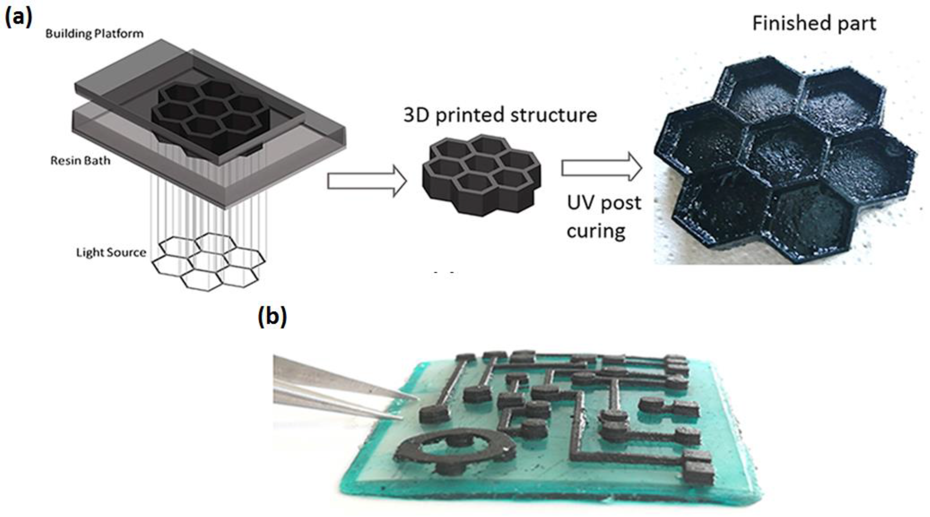
Overcoming the usual nozzle jam issue while nanocomposites are processed using the Fused Deposition Modeling (FDM) technique, Gnanasekaran et al. [76] printed non-conventional polymer nanocomposites (CNT- and graphene-based polybutylene terephthalate (PBT)) on a commercially available desktop 3D printer. It was addressed that the nozzle jam issue can be controlled by the optimization of the size and size distribution of the conductive fillers as well as the printing parameters/conditions, such as printing temperature, printing speed, residence time and printing bed temperature. In this study, CNT and graphene dispersions were achieved in PBT by sonicating the nanoparticles in isopropanol solvent in an ice bath and subsequent vigorous stirring after adding the PBT while evaporating the solvent. In this way, PBT powder containing conductive fillers was processed and extruded later to obtain composite filaments for 3DP. The printed structures were characterized for electrical conductivity, morphology, crystallization behavior, thermal stability and viscoelastic behavior. It was found that PBT/CNT 3D printed structures have better functional properties (elastic behavior and conductive properties) than that of the PBT/G 3D printed structures. The authors concluded with some vital recommendations/comments regarding the printing of abrasive materials since such materials could potentially damage the printing nozzle. The recommendation includes manufacturing the FDM nozzles using harder materials, such as silicon carbide. It was also stated that change in nozzle design such as use of co-extruding nozzles instead of double nozzles could help with the clogging of conductive fillers. Health and safety issues upon printing ultra-small nanoparticles is another vital concern in this field which should be addressed properly in the manufacturing environment. Gonzalez et al. [77] studied the blend of PEGDA and PEGMEMA and mixed the MWNTs into it. The authors achieved the CNT dispersion by sonicating PEGMEMA/CNT mixture, followed by high-shear homogenizing the mixture after addition of PEGDA resin and BAPO photoinitiator. Digital light processing (DLP) technique was used to print a series of objects such as 3 mm cubes, sub-mm films, cm-scale hexagonal structures (Figure 2a) and a circuit model (Figure 2b) and the mechanical and electrical properties of the polymer/CNT nanocomposites were evaluated. It was found that the addition of CNTs to the formulation causes a slight decrease in crosslinking density, which reduces its mechanical performance. However, it was found that with the addition of as low as 0.1 wt. % of CNTs, the conductivity rises almost 3 orders or magnitude with respect to the pure PEGDA:PEGMEMA 1:1.5 formulation. Tsiakatouras et al. [78] processed ABS filaments with different CNT concentrations and conducted a comparative mechanical properties study between injection molding, a conventional manufacturing method and 3DP. Carbon fibers (CF) were also introduced into the 3D printed specimens during printing, however, no further details regarding the type of CF and the process of addition were discussed in this work. It was found that injection molding produces more rigid structures compared to that of 3DP, however, 3DP showed better manufacturing flexibility because of rapid prototyping by producing commercial objects which are possible to test under real operational conditions and by in situ incorporation of carbon fibres.
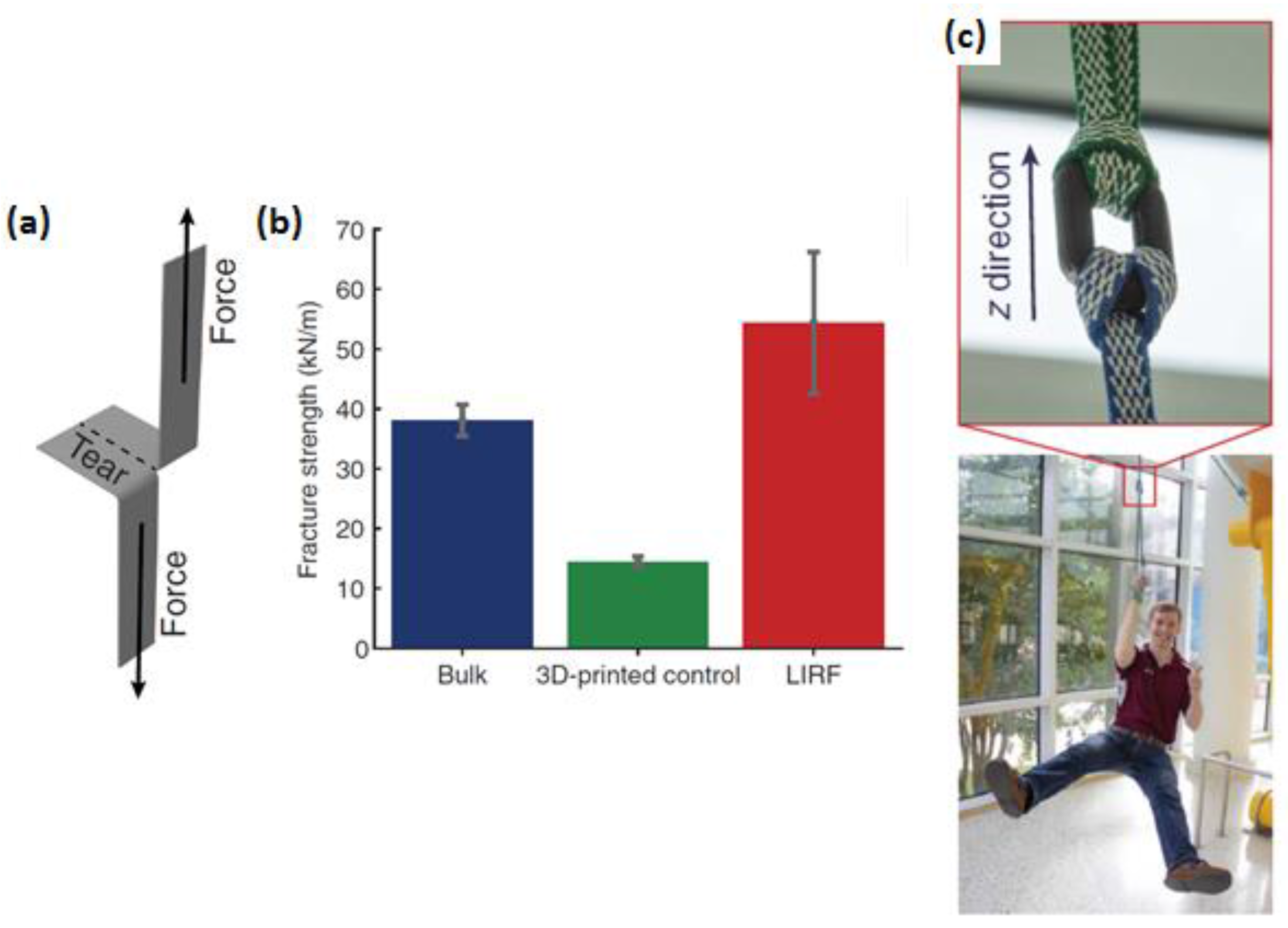
To improve the weak weld zone between successive filament traces in the 3D printed plastic engineering parts, Sweeney et al. [79] developed a novel concept for welding 3D printed thermoplastic interfaces. The authors used intense localized heating of carbon nanotubes (CNTs) by microwave irradiation which was introduced as locally induced RF (LIRF) welding method. As shown in Figure 3a, 3D printed filaments result in a macroscopic structure with MWCNTs localized only at the interfaces between each trace because of the MWCNT-rich polymer film coating around the thermoplastic filaments. Upon exposure to microwave irradiation as can be seen in Figure 3b, these MWCNTs loaded interfaces create localized heating, which promotes increased local polymer mobility and entanglement across the interface. To characterize the weld strength, a single 3D printed layer weld line was subjected to trouser tear tests, as shown in Figure 4a. In this method, the sample is torn such that the fracture propagates along a single z direction weld line. It was found that fracture strength increased by 275% over baseline 3D-printed parts. SEM images of the fracture surfaces further showed that the fracture surface of the LIRF-welded samples exhibit large necked zones along the tear path with significant bulk plastic deformation which closely resembled that of the bulk hot-pressed PLA films. This suggested that both the strength and ductility of the LIRF-welded samples have been restored as the bulk film sample. The authors demonstrated impressive load-supporting structures with complex shapes such as the 3D-printed chain link (Figure 4b).
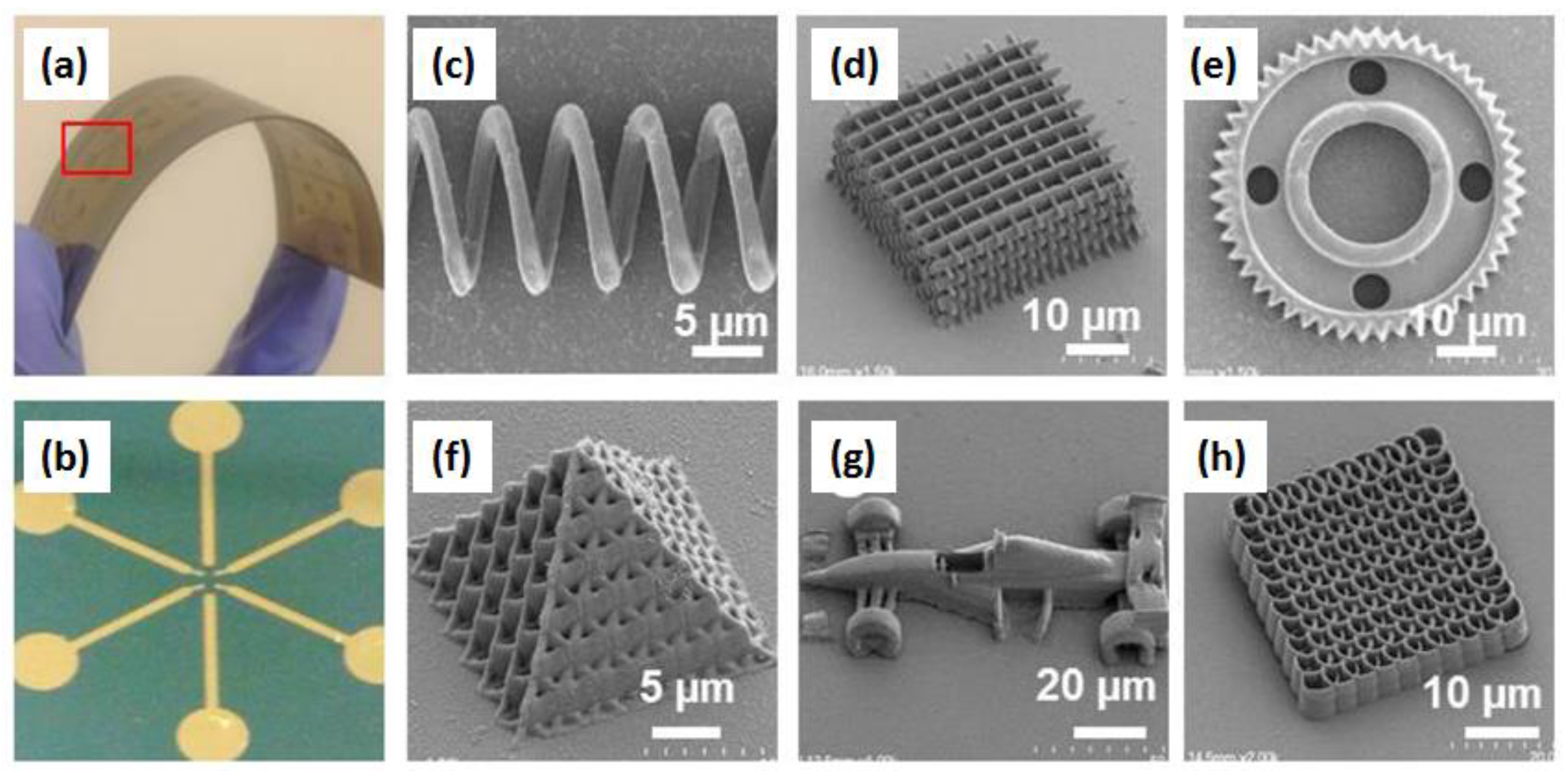
Liu et al. [80] fabricated arbitrary 3D micro/nanostructures (Figure 5) from MWNT-thiol-acrylate (MTA) composite resins via TPP technique with ultrahigh spatial resolution. For TPP fabrication, MTA composite resin was prepared by mixing acid-purified MWNTs and thiol-acrylate using ultrasonic agitation under ice bath. Large agglomerated MWNTs were removed using high-speed centrifugation. The authors confirmed excellent distribution of MWNTs with high concentrations and stability in the MTA composite. It was found that with 0.2 wt. % MWNTs loaded into the acrylate polymer, the electrical conductivity of the composite resin increased over 11 orders of magnitude and reached 46.8 S/m. Wu et al. [81] prepared printing ink by milling CNTs in a solution composed of isopropyl alcohol, ethylene glycol, and the dispersion agent. This ink was used to make carbon nanotubes-based 3D printed microsupercapacitors (MSCs). The printing was carried out via a micronozzle, with printing speeds and micronozzle-to-base distances controlled, and with predesigned base temperature and preprogrammed printing trajectory. It was claimed that the heated base introduces benefits such as (a) lowering the demand of highly concentrated solid contents which is required in the traditional extrusion-based 3D printing and (b) promoting adhesion between the printed features. MSCs produced utilizing this method deliver a specific capacitance of 2.44 F cm−2 and exhibit superior cycle stability and reliable energy storage capacity.
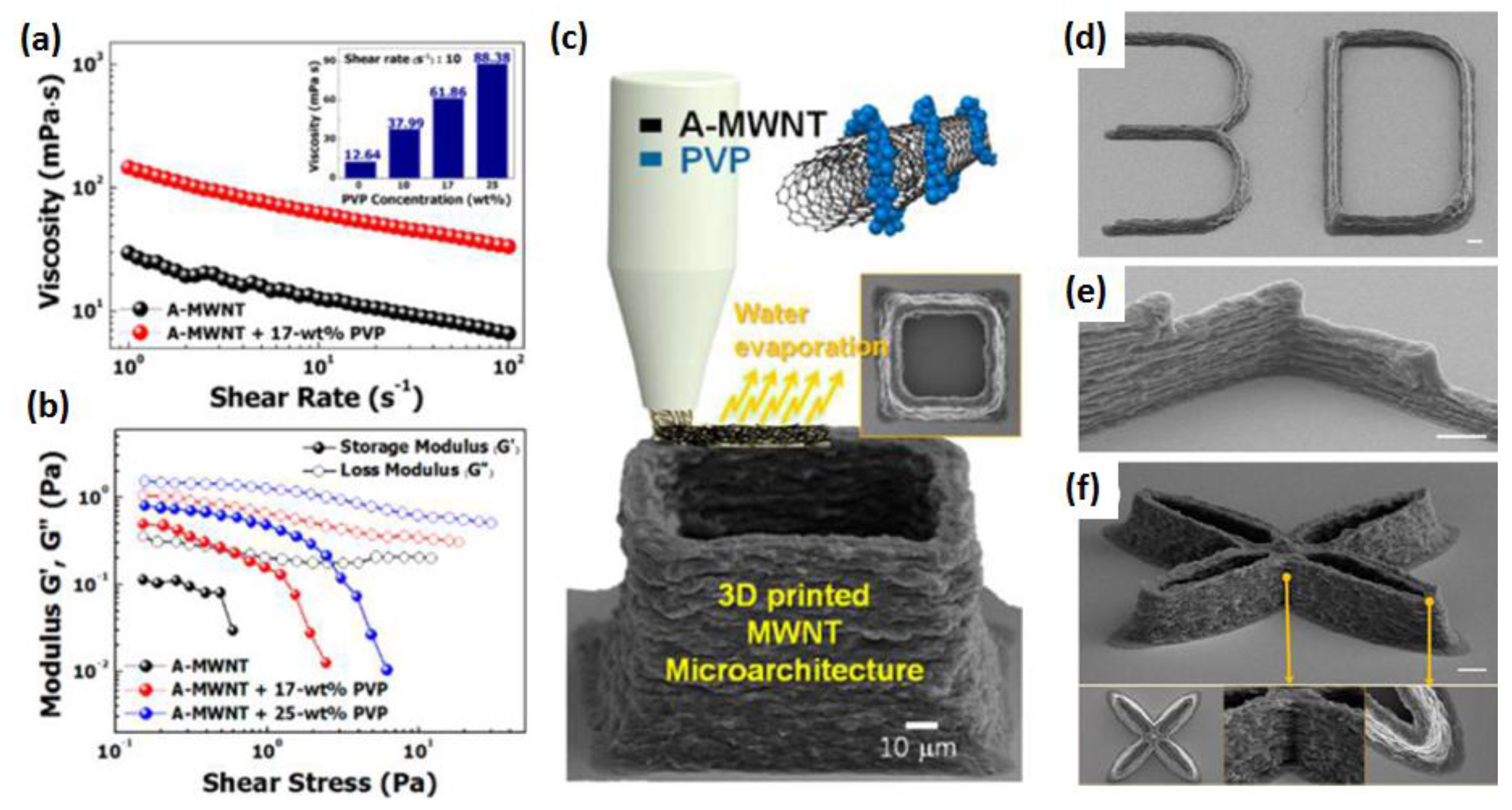
Kim et al. [82] demonstrated a 3D-printing strategy to produce highly conductive 3D MWNT microarchitectures with a MWNT concentration as high as ~75 wt. % via meniscus-guided printing method [83]. In this method, CNT aqueous ink was composed of MWNTs and polyvinylpyrrolidone (PVP). Later, PVP was removed via thermal decomposition at 450 °C for 1 h in vacuum. Rheological properties of CNT inks showed clear shear thinning behavior, occurring from the rearrangement of MWNTs under shear stress (Figure 6a) and fluid-like behavior (G′ is lower than G″) (Figure 6b). 3D MWNT microstructures were printed using the developed CNT fluid ink as shown in Figure 6c–f. It was pointed out that the key factor for the successful 3D printing of MWNT structures presented in this study was the modification of the MWNT suspension. Since the A-MWNT suspension did not possess the required rheological behavior for 3D-printable ink, addition of PVP to the suspension improved the CNT ink printability. Thus, uniform dispersion and appropriate rheological properties of the PCP/CNT suspension ensured consistent flow through a confined nozzle geometry.
Recently, Chizari et al. [84] fabricated highly conductive CNTs/PLA nanocomposites used as 3D printable conductive inks for fabrication of conductive scaffold structures. A ball mill mixing method was used to disperse the MWCNTs with a concentration up to 40 wt. % in PLA, however, it was reported that up to 30 wt. % of CNT concentration was 3D printable without blocking of the printing nozzle and fragility of the printed structures. The dried CNT/PLA composites were dissolved in dichloromethane (DCM) and the CNT/PLA-DCM was used directly after mixing as the printing ink using solvent cast 3DP method. It was found that the sensitivity of the liquid sensors decreased by increasing the filament diameter and/or the thickness of the fabricated scaffolds. On the other hand, the scaffold showed electrical conductivity of up to ≈2350 S/m−1 which is higher than that of many recently reported polymer based conductive composites (maximum < 100 S/m−1) suitable for 3D printing [84]. Gonçalves et al. [85] demonstrated that a 3D printed nanocomposite scaffold system possesses enough compressive strength and electrical conductivity along with bioactivity, biocompatibility, porosity, and pore size which could be a suitable option for the application in the field of bone regenerative medicine. The scaffold was printed from three-phase monocrystalline hydroxyapatite (HA)/CNTs/PCL system with optimum viscosity. The CNT/HA suspension was homogenized for 1 hour to mix HA and CNTs. PCL solution was then added to the suspension to prepare the slurry for printing. Maximum CNT concentration used in this study was 10 wt. % and no nozzle jam was reported. CNT loading was optimized and it was found that 2% CNT scaffold offers the best combination of mechanical behavior and electrical conductivity for scaffold application. Selective laser sintering (SLS) was used by Li et al. [86] to prepare the flexible thermoplastic polyurethane (TPU) conductor using self-made MWCNTs wrapped TPU powder. The authors claimed that having lower percolation threshold, the electrical conductivity for the SLS processed TPU/CNTs composite reached ≈10−1 S/m−1 at 1 wt. % CNTs content, which is seven orders of magnitude higher than that of conventional injection-molded TPU/CNTs composites at the same CNTs content. In this study, CNT dispersion in ethanol was carried out by ultrasonication. The TPU powder was then added to the CNTs suspension and mechanically stirred before filtered and dried to obtain the MWCNTs wrapped TPU powder. For the printed flexible nanocomposites, no considerable change was observed after 1000 bending cycles, but there was a decrease in mechanical strength to some extent.
3. Applications
This review is directed at providing an overview on the up-to-date on-going research in the field of manufacturing of polymer/CNT nanocomposites using 3DP, along with their potential applications. A summary of the recent investigates as discussed in the previous section are presented in Table 2. From the table, it is clear that the most widespread use of 3D printed CNT nanocomposites is in electronics. More specifically, owing to the outstanding electrical conductivity (102 S/m to 107 S/m at 300 K) of CNTs [33], most of the 3D printed polymer/CNT nanocomposites structures are concentrated on improving electrical properties. The applications of the polymer/CNT nanocomposites include energy storage devices like microsupercapacitors, electronic components such as transducers, flexible conductor, emitters, and radio frequency inductors, absorber of electromagnetic energy, liquid sensors such as gas or strain sensors, precise electrical micro-interconnectors in 3D circuits and so on. High electrically conductive polymer/CNT nanocomposites can be beneficial as the 3D printable biomaterials electrical stimuli to enhance the cell functions [85]. As significant improvement in electrical conductivity is observed at very low CNT loading, 3D printed precise macro and micro-structured CNT/polymer nanocomposites could be a light weight, low cost and highly effective option for particular applications. Other than that, very high tensile modulus (270 GPa–950 GPa) and tensile strength (11 GPa–63 GPa) [28] of CNTs qualified them as an appropriate candidate for reinforcement in 3D printed nanocomposites to address their strength limitations. The incorporation of CNTs could also improve the thermal transport properties of polymer composites due to the excellent thermal conductivity (200 W/m/K–3000 W/m/K at 300 K) [31,87] of CNTs.
It is predicted that by 2019, the 3DP market will reach $10 billion (with an annual growth rate (CAGR) of 32.2% from 2014 to 2019) which was only $1 billion by 2009 after more than 20 years of exploitation. It is worth noting that it took only three more years to reach $2 billion, which highlights the prospect of this industry [88,89]. CNT nanocomposites will undoubtedly be a part of this growth which opens up a new age of advanced multifunctional materials.
4. Conclusions and Future Developments
Recent studies presented in this review on 3D printed CNT/polymer nanocomposite suggest its enormous potential in the respective fields. However, in spite of the rapid evolution of the 3DP technique towards different applications from simple devices for day to day use to high-tech complex structures, significant gaps still remain in the knowledge relating to the introduction of CNTs as a part of nanocomposites manufactured using 3DP technique.
First and foremost, carbon nanotube dispersion is the biggest challenge in realizing the full potential of CNTs, which is addressed by many researchers. It was found that sonication, homogenization and other mechanical mixing are the tools employed for the separation of entangled or agglomerated CNTs and centrifugation for filtering out the agglomerated residue. Non-covalent and covalent functionalization of the CNTs and/or coating or wrapping of the individual nanotubes using appropriate compatibilizer [35] could be an effective route while processing 3D printed CNT/polymer nanocomposite and it needs further exploration. Chemical functionalization purposefully creates defects on the CNT surface which subsequently generates active functional groups. These newly created functional groups assist the bonding between the CNT and the polymer chain [90]. It was found that acid treated CNTs could improve the electrical conductivity of the composites compared with that of CNT-polymer composites made from the same pristine CNTs [91]. At the same time, it is important that such types of additional processing steps are economically viable and scalable preserving the intrinsic properties of CNTs. Too many defects caused by the nanotube functionalization could potentially degrade the properties of the CNTs and thus adversely affect the composite properties. Aside from dispersion, surface tension and viscosity of the inks are other important characteristics that the researchers considered while processing nanocomposites for certain 3DP applications. These parameters are largely dependent on the CNT loading, dispersion in the matrix, alignment of CNTs with the polymer chain and interaction between the polymer and the CNTs. Good mechanical reinforcement of the nanocomposites is another important criterion for better mechanical properties of the nanocomposites. Such a reinforcement could be tailored by the types of CNTs (MWCNT or SWCNT), diameter and length of CNTs (aspect ratio) other than the parameters stated above. Systematic studies optimizing all of these parameters are essential for user specific 3D printed CNT/polymer nanocomposites production.
As a final remark, it can be concluded that recent rapid progress in the 3D printed polymer/CNT nanocomposites is leading to new, exciting developments and breakthroughs targeting the theoretical or fundamental aspects as well as the commercialization of new materials.
Acknowledgments
Fruitful discussion with Bapi Sarker (Postdoctoral Research Associate at Washington University in St. Louis, MO, USA) is gratefully acknowledged.
Conflicts of Interest
The author declares no conflict of interest.
References
- Wimpenny, D.I.; Pandey, P.M.; Kumar, L.J. Advances in 3D Printing & Additive Manufacturing Technologies; Springer: Berlin, Germany, 2016. [Google Scholar]
- Chua, C.K.; Wong, C.H.; Yeong, W.Y. Standards, Quality Control, and Measurement Sciences in 3D Printing and Additive Manufacturing; Academic Press: Cambridge, MA, USA, 2017. [Google Scholar]
- Badiru, A.B.; Valencia, V.V.; Liu, D. Additive Manufacturing Handbook: Product Development for the Defense Industry; CRC Press: Boca Raton, FL, USA, 2017. [Google Scholar]
- Matsuzaki, R.; Ueda, M.; Namiki, M.; Jeong, T.-K.; Asahara, H.; Horiguchi, K.; Nakamura, T.; Todoroki, A.; Hirano, Y. Three-Dimensional Printing of Continuous-Fiber Composites by In-Nozzle Impregnation. Sci. Rep. 2016, 6, 23058. [Google Scholar] [CrossRef] [PubMed]
- Xiaocong, T.; Jun, J.; Shangqin, Y.; Kai, C.C.; Beng, T.S.; Kun, Z. Emerging 3D-Printed Electrochemical Energy Storage Devices: A Critical Review. Adv. Energy Mater. 2017, 7, 1614–6840. [Google Scholar]
- Lewis, J.; Ahn, B.Y. Device Fabrication: Three-Dimensional Printed Electronics. Nature 2015, 518, 42–43. [Google Scholar] [CrossRef] [PubMed]
- Lewicki, J.P.; Rodriguez, J.N.; Zhu, C.; Worsley, M.A.; Wu, A.S.; Kanarska, Y.; Horn, J.D.; Duoss, E.B.; Ortega, J.M.; Elmer, W.; et al. 3D-Printing of Meso-structurally Ordered Carbon Fiber/Polymer Composites with Unprecedented Orthotropic Physical Properties. Sci. Rep. 2017, 7, 43401. [Google Scholar] [CrossRef] [PubMed]
- Bose, S.; Vahabzadeh, S.; Bandyopadhyay, A. Bone tissue engineering using 3D printing. Mater. Today 2013, 16, 496–504. [Google Scholar] [CrossRef]
- Kalaskar, D.M. 3D Printing in Medicine; Woodhead Publishing: Duxford, UK, 2017. [Google Scholar]
- Farahani, R.D.; Dubé, M.; Therriault, D. Three-Dimensional Printing of Multifunctional Nanocomposites: Manufacturing Techniques and Applications. Adv. Mater. 2016, 28, 5794–5821. [Google Scholar] [CrossRef] [PubMed]
- Lipson, H.; Francis, C.M.; Jimmy, H.; Paventi, C. 3-D printing the history of mechanisms. J. Mech. Des. 2005, 127, 1029. [Google Scholar] [CrossRef]
- Jacobs, P.F. Rapid Prototyping & Manufacturing: Fundamentals of Stereolithography; Society of Manufacturing Engineers: Dearborn, MI, USA, 1992. [Google Scholar]
- Tian, X.Y.; Tian, T.F.; Yang, C.C.; Wang, Q.R.; Li, D.C. Interface and performance of 3D printed continuous carbon fiber reinforced PLA composites. Compos. A Appl. Sci. Manuf. 2016, 88, 198–205. [Google Scholar] [CrossRef]
- Lee, J.-Y.; An, J.; Chua, C.K. Fundamentals and applications of 3D printing for novel materials. Appl. Mater. Today 2017, 7, 120–133. [Google Scholar] [CrossRef]
- Acquah, S.F.A.; Leonhardt, B.E.; Nowotarski, M.S.; Magi, J.M.; Chambliss, K.A.; Venzel, T.E.S.; Delekar, S.D.; Al-Hariri, L. Carbon Nanotubes and Graphene as Additives in 3D Printing (Chapter 8). In Carbon Nanotubes—Current Progress of their Polymer Composites; Berber, M.R., Ed.; InTech: Rijeka, Croatia, 2016. [Google Scholar] [CrossRef]
- Liu, H.; Webster, T.J. Enhanced biological and mechanical properties of well-dispersed nanophase ceramics in polymer composites: From 2D to 3D printed structures. Mater. Sci. Eng. C 2011, 31, 77–89. [Google Scholar] [CrossRef]
- Wang, X.; Jiang, M.; Zhou, Z.W.; Gou, J.H.; Hui, D. 3D printing of polymer matrix composites: A review and prospective. Compos. B Eng. 2017, 110, 442–458. [Google Scholar] [CrossRef]
- Cunico, M.W.M.; Carvalho, J.D. Development of novel additive manufacturing technology: An investigation of a selective composite formation process. Rapid Prototyp. J. 2016, 22, 51–66. [Google Scholar] [CrossRef]
- Lukic, M.; Clarke, J.; Tuck, C.; Whittow, W.; Wells, G. Printability of elastomer latex for additive manufacturing or 3D printing. J. Appl. Polym. Sci. 2016, 133. [Google Scholar] [CrossRef] [Green Version]
- Cunico, M.W.M.; Carvalho, J.D. Development of acrylate-based material using a multivariable approach: Additive manufacturing applications. Rapid Prototyp. J. 2014, 20, 121–132. [Google Scholar] [CrossRef]
- Weng, Z.X.; Zhou, Y.; Lin, W.X.; Senthil, T.; Wu, L.X. Structure-property relationship of nano enhanced stereolithography resin for desktop SLA 3D printer. Compos. A Appl. Sci. Manuf. 2016, 88, 234–242. [Google Scholar] [CrossRef]
- Amel, H.; Rongong, J.; Moztarzadeh, H.; Hopkinson, N. Effect of section thickness on fatigue performance of laser sintered nylon 12. Polym. Test. 2016, 53, 204–210. [Google Scholar] [CrossRef]
- Schmid, M.; Wegener, K. Additive manufacturing: polymers applicable for laser sintering (LS). Procedia Eng. 2016, 49, 457–464. [Google Scholar] [CrossRef]
- Fu, K.; Yao, Y.Y.; Dai, J.Q.; Hu, L.B. Progress in 3D Printing of Carbon Materials for Energy-Related Applications. Adv. Mater. 2017, 29, 1603486. [Google Scholar] [CrossRef] [PubMed]
- Jin, Y.F.; Liu, C.C.; Chai, W.X.; Compaan, A.; Huang, Y. Self-Supporting Nanoclay as Internal Scaffold Material for Direct Printing of Soft Hydrogel Composite Structures in Air. ACS Appl. Mater. Interfaces 2017, 9, 17456–17465. [Google Scholar] [CrossRef] [PubMed]
- Zhai, X.Y.; Ma, Y.F.; Hou, C.Y.; Gao, F.; Zhang, Y.Y.; Ruan, C.S.; Pan, H.B.; Lu, W.J.; Liu, W.G. 3D-Printed High Strength Bioactive Supramolecular Polymer/Clay Nanocomposite Hydrogel Scaffold for Bone Regeneration. ACS Biomater. Sci. Eng. 2017, 3, 1109–1118. [Google Scholar] [CrossRef]
- Iijima, S. Helical microtubules of graphitic carbon. Nature 1991, 56, 354. [Google Scholar] [CrossRef]
- Yu, M.-F.; Lourie, O.; Dyer, M.J.; Moloni, K.; Kelly, T.F.; Ruoff, R.S. Strength and breaking mechanism of multiwalled carbon nanotubes under tensile load. Science 2000, 287, 637–640. [Google Scholar] [CrossRef] [PubMed]
- Bachilo, S.M. Structure-assigned optical spectra of single walled carbon nanotubes. Science 2002, 298, 2361–2366. [Google Scholar] [CrossRef] [PubMed]
- Tans, S.J.; Devoret, M.H.; Dai, H.J.; Thess, A.; Smalley, R.E.; Geerligs, L.J.; Dekker, C. Individual single-wall carbon nanotubes as quantum wires. Nature 1997, 386, 474–477. [Google Scholar] [CrossRef]
- Samani, M.K.; Khosravian, N.; Chen, G.C.K.; Shakerzadeh, M.; Baillargeat, D.; Tay, B.K. Thermal conductivity of individual multiwalled carbon nanotubes. Int. J. Therm. Sci. 2012, 62, 40–43. [Google Scholar] [CrossRef]
- Hone, J.; Batlogg, B.; Benes, Z.; Johnson, A.; Fischer, J.E. Quantized phonon spectrum of single-wall carbon nanotubes. Science 2000, 289, 1730–1733. [Google Scholar] [CrossRef] [PubMed]
- Ebbesen, T.W.; Lezec, H.J.; Hiura, H. Electrical-conductivity of individual carbon nanotubes. Nature 1996, 382, 54–56. [Google Scholar] [CrossRef]
- Schlagenhauf, L.; Nüesch, F.; Wang, J. Release of Carbon Nanotubes from Polymer Nanocomposites. Fibers 2014, 2, 108–127. [Google Scholar] [CrossRef]
- Wang, P.; Ghoshal, S.; Gulgunje, P.; Verghese, N.; Kumar, S. Polypropylene nanocomposites with polymer coated multiwall carbon nanotubes. Polymer 2016, 100, 244–258. [Google Scholar] [CrossRef]
- Newcomb, B.A.; Chae, H.G.; Gulgunje, P.V.; Gupta, K.; Liu, Y.D.; Tsentalovich, D.E.; Pasquali, M.; Kumar, S. Stress Transfer in Polyacrylonitrile/Carbon Nanotube Composite Fibers. Polymer 2014, 55, 2734–2743. [Google Scholar] [CrossRef]
- Xie, L.; Xu, F.; Qiu, F.; Lu, H.B.; Yang, Y.L. Single-Walled Carbon Nanotubes Functionalized with High Bonding Density of Polymer Layers and Enhanced Mechanical Properties of Composites. Macromolecules 2007, 40, 3296–3305. [Google Scholar] [CrossRef]
- Downes, R.D.; Hao, A.; Park, J.G.; Su, Y.-F.; Liang, R.; Jensen, B.D.; Siochi, E.J.; Wise, K.E. Geometrically Constrained Self-Assembly and Crystal Packing of Flattened and Aligned Carbon Nanotubes. Carbon 2015, 93, 953–966. [Google Scholar] [CrossRef]
- Minus, M.L.; Chae, H.G.; Kumar, S. Polyethylene Crystallization Nucleated by Carbon Nanotubes under Shear. ACS Appl. Mater. Interfaces 2012, 4, 326–330. [Google Scholar] [CrossRef] [PubMed]
- Minus, M.L.; Chae, H.G.; Kumar, S. Single Wall Carbon Nanotube Templated Oriented Crystallization of Poly(Vinyl Alcohol). Polymer 2006, 47, 3705–3710. [Google Scholar] [CrossRef]
- Chae, H.G.; Minus, M.L.; Kumar, S. Oriented and Exfoliated Single Wall Carbon Nanotubes in Polyacrylonitrile. Polymer 2006, 47, 3494–3504. [Google Scholar] [CrossRef]
- Zhang, Y.Y.; Song, K.N.; Meng, J.S.; Minus, M.L. Tailoring Polyacrylonitrile Interfacial Morphological Structure by Crystallization in the Presence of Single-Wall Carbon Nanotubes. ACS Appl. Mater. Interfaces 2013, 5, 807–814. [Google Scholar] [CrossRef] [PubMed]
- Zhang, Y.; Tajaddod, N.; Song, K.N.; Minus, M.L. Low Temperature Graphitization of Interphase Polyacrylonitrile (PAN). Carbon 2015, 91, 479–493. [Google Scholar] [CrossRef]
- Li, L.; Li, C.Y.; Ni, C.Y. Polymer Crystallization-Driven, Periodic Patterning on Carbon Nanotubes. J. Am. Chem. Soc. 2006, 128, 1692–1699. [Google Scholar] [CrossRef] [PubMed]
- Zong, G.Y.; Zhang, W.; Ning, N.Y.; Tang, C.Y.; Yang, M.B.; Fu, Q. Study of PE and iPP Orientations on the Surface of Carbon Nanotubes by Using Molecular Dynamic Simulations. Mol. Simul. 2013, 39, 1013–1021. [Google Scholar] [CrossRef]
- Rothschild, A.; Sloan, J.; Tenne, R. Growth of WS2 nanotubes phases. J. Am. Chem. Soc. 2000, 122, 5169–5179. [Google Scholar] [CrossRef]
- Nath, M.; Govindaraj, A.; Rao, C.N.R. Simple synthesis of MoS2 and WS2 nanotubes. Adv. Mater. 2001, 13, 283–286. [Google Scholar] [CrossRef]
- Dloczik, L.; Engelhardt, R.; Ernst, K.; Fiechter, S.; Sieber, I.; Könenkamp, R. Hexagonal nanotubes of ZnS by chemical conversion of monocrystalline ZnO columns. Appl. Phys. Lett. 2001, 78, 3687. [Google Scholar] [CrossRef]
- Lourie, O.R.; Jones, C.R.; Bartlett, B.M.; Buhro, W. CVD growth of boron nitride nanotubes. Chem. Mater. 2000, 12, 1808–1810. [Google Scholar] [CrossRef]
- Ye, C.; Ye, C.H.; Meng, G.W.; Jiang, Z.; Zhang, L. Rational growth of Bi2S3 nanotubes from quasi-twodimensional precursors. J. Am. Chem. Soc. 2002, 124, 15180–15181. [Google Scholar] [CrossRef] [PubMed]
- Nath, M.; Rao, C.N.R. New metal disulfide nanotubes. J. Am. Chem. Soc. 2001, 123, 4841–4842. [Google Scholar] [CrossRef] [PubMed]
- Galvan, D.H. Formation of NbSe2 nanotubes by electron irradiation. Fuller. Sci. Technol. 2000, 8, 143–151. [Google Scholar] [CrossRef]
- Wu, Q.; Hu, Z.; Wang, X.Z.; Lu, Y.N.; Chen, X.; Xu, H.; Chen, Y. Synthesis and characterization of faceted hexagonal aluminum nitride nanotubes. J. Am. Chem. Soc. 2003, 125, 10176–10177. [Google Scholar] [CrossRef] [PubMed]
- Goldberger, J.; He, R.; Zhang, Y.F.; Lee, S.; Yan, H.Q.; Chol, H.-J.; Yang, P. Single-crystal gallium nitride nanotubes. Nature 2003, 422, 599–602. [Google Scholar] [CrossRef] [PubMed]
- Bakkers, E.P.A.M.; Verheijen, M.A. Synthesis of InP nanotubes. J. Am. Chem. Soc. 2003, 125, 3440–3441. [Google Scholar] [CrossRef] [PubMed]
- Fan, R. Fabrication of silica nanotube arrays from vertical silicon nanowire templates. J. Am. Chem. Soc. 2003, 125, 5254–5255. [Google Scholar] [CrossRef] [PubMed]
- Zhang, X.H.; Xie, S.-Y.; Jiang, Z.-Y.; Zhang, X.; Tian, Z.-Q.; Xie, Z.-X.; Huang, R.-B.; Zheng, L.-S. Rational Design and Fabrication of Zno Nanotubes from Nanowire Templates in a Microwave Plasma System. J. Phys. Chem. B 2003, 107, 10114. [Google Scholar] [CrossRef]
- Baddour, C.E.; Briens, C. Carbon Nanotube Synthesis: A Review. Int. J. Chem. React. Eng. 2005, 3, R3. [Google Scholar] [CrossRef]
- Kong, Y.; Yuan, J.; Wang, Z.M.; Qiu, J. Study on the preparation and properties of aligned carbon nanotubes/polylactide composite fibers. Polym. Compos. 2012, 33, 1613–1619. [Google Scholar] [CrossRef]
- Thess, A.; Lee, R.; Nikolaev, P.; Dai, H.J.; Petit, P.; Robert, J.; Xu, C.H.; Lee, Y.H.; Kim, S.G.; Rinzler, A.G.; et al. Crystalline ropes of metallic carbon nanotubes. Science 1996, 273, 483–487. [Google Scholar] [CrossRef] [PubMed]
- Murray, A.R.; Kisin, E.R.; Tkach, A.V.; Yanamala, N.; Mercer, R.; Young, S.H.; Fadeel, B.; Kagan, V.E.; Shvedova, A.A. Factoring-in agglomeration of carbon nanotubes and nanofibers for better prediction of their toxicity versus asbestos. Part. Fibre Toxicol. 2012, 9, 10. [Google Scholar] [CrossRef] [PubMed]
- Chu, C.-C.; White, K.L.; Liu, P.L.; Zhang, X.; Sue, H.-J. Electrical conductivity and thermal stability of polypropylene containing well-dispersed multi-walled carbon nanotubes disentangled with exfoliated nanoplatelets. Carbon 2012, 50, 4711–4721. [Google Scholar] [CrossRef]
- Bhattacharyya, A.R.; Sreekumar, T.V.; Liu, T.; Kumar, S.; Ericson, L.M.; Hauge, R.H.; Smalley, R. Crystallization and orientation studies in polypropylene/single wall carbon nanotube composite. Polymer 2003, 44, 2373–2377. [Google Scholar] [CrossRef]
- Zhang, S.; Minus, M.; Zhu, L.B.; Wong, C.-P.; Kumar, S. Polymer transcrystallinity induced by carbon nanotubes. Polymer 2008, 49, 1356–1364. [Google Scholar] [CrossRef]
- Anand, K.A.; Agarwal, U.S.; Joseph, R. Carbon nanotubes induced crystallization of poly(ethylene terephthalate). Polymer 2006, 47, 3976–3980. [Google Scholar] [CrossRef]
- Zhang, S.; Kumar, S. Shaping polymer particles by carbon nanotubes. Macromol. Rapid Commun. 2008, 29, 557–561. [Google Scholar] [CrossRef]
- Wei, X.J.; Li, D.; Jiang, W.; Gu, Z.; Wang, X.J.; Zhang, Z.X.; Sun, Z.Z. 3D printable graphene composite. Sci. Rep. 2015, 5, 11181. [Google Scholar] [CrossRef] [PubMed]
- Ghoshal, S.; Wang, P.; Gulgunje, P.; Verghese, N.; Kumar, S. High Impact Strength Polypropylene Containing Carbon Nanotubes. Polymer 2016, 100, 259–274. [Google Scholar] [CrossRef]
- Sandoval, J.H.; Soto, K.F.; Murr, L.E.; Wicker, R.B. Nanotailoring Photocrosslinkable Epoxy Resins with Multi-Walled Carbon Nanotubes for Stereolithography Layered Manufacturing. J. Mater. Sci. 2007, 42, 156. [Google Scholar] [CrossRef]
- Zhang, Y.Y.; Li, H.M.; Yang, X.; Zhang, T.; Zhu, K.Q.; Si, W.; Liu, Z.L.; Sun, H.J. Additive Manufacturing of Carbon Nanotube-Photopolymer Composite Radar Absorbing Materials. Polym. Compos. 2016. [Google Scholar] [CrossRef]
- Postiglione, G.; Natale, G.; Griffini, G.; Levi, M.; Turri, S. Conductive 3D Microstructures by Direct 3D Printing of Polymer/Carbon Nanotube Nanocomposites via Liquid Deposition Modeling. Compos. A Appl. Sci. Manuf. 2015, 76, 110–114. [Google Scholar] [CrossRef]
- Guo, S.; Yang, X.; Heuzey, M.-C.; Therriault, D. 3D Printing of a Multifunctional Nanocomposite Helical Liquid Sensor. Nanoscale 2015, 7, 6451–6456. [Google Scholar] [CrossRef] [PubMed]
- Ushiba, S.; Shoji, S.; Masui, K.; Kuray, P.; Kono, J.; Kawata, S. 3D Microfabrication of Single-Wall Carbon Nanotube/Polymer Composites by Two-Photon Polymerization Lithography. Carbon 2013, 59, 283–288. [Google Scholar] [CrossRef]
- Li, Y.; Qi, F.J.; Yang, H.; Gong, Q.H.; Dong, X.Z.; Duan, X.M. Nonuniform shrinkage and stretching of polymerized nanostructures fabricated by two-photon polymerization. Nanotechnology 2008, 19, 055303. [Google Scholar] [CrossRef] [PubMed]
- Takada, K.; Wu, D.; Chen, Q.-D.; Shoji, S.; Xia, H.X.; Kawata, S.; Sun, H.-B. Size-dependent behaviors of femtosecond laser-phototyped polymer micronanowires. Opt. Lett. 2009, 34, 566–568. [Google Scholar] [CrossRef] [PubMed]
- Gnanasekaran, K.; Heijmans, T.; Bennekom, S.V.; Woldhuis, H.; Wijnia, S.; With, G.D.; Friedrich, H. 3D Printing of CNT- and Graphene-Based Conductive Polymer Nanocomposites by Fused Deposition Modeling. Appl. Mater. Today 2017, 9, 21–28. [Google Scholar] [CrossRef]
- Gonzalez, G.; Chiappone, A.; Roppolo, L.; Fantino, E.; Bertanna, V.; Perrucci, F.; Scaltrito, L.; Pirri, F.; Sangermano, M. Development of 3D Printable Formulations Containing CNT with Enhanced Electrical Properties. Polymer 2017, 109, 246–253. [Google Scholar] [CrossRef]
- Tsiakatouras, G.; Chiappone, A.; Roppolo, I.; Fantino, E.; Bertana, V.; Perrucci, F.; Scaltrito, L.; Pirri, F.; Sangermano, M. Comparative Study on Nanotubes Reinforced with Carbon Filaments for the 3D Printing of Mechanical Parts. World Trans. Eng. Technol. Educ. 2014, 12, 392–396. [Google Scholar]
- Sweeney, C.B.; Lackey, B.A.; Pospisil, M.J.; Achee, T.C.; Hicks, V.K.; Moran, A.G.; Teipel, B.R.; Saed, M.A.; Green, M.J. Welding of 3D-Printed Carbon Nanotube—Polymer Composites by Locally Induced Microwave Heating. Sci. Adv. 2017, 3, 1700262. [Google Scholar] [CrossRef] [PubMed]
- Liu, Y.; Xiong, W.; Jiang, L.J.; Zhou, Y.S.; Lu, Y.F. Precise 3D Printing of Micro/Nanostructures using Highly Conductive Carbon Nanotube-Thiol-Acrylate Composites. SPIE Proc. 2016, 9738, 973808. [Google Scholar]
- Yu, W.; Zhou, H.; Li, B.Q.; Ding, S.J. 3D Printing of Carbon Nanotubes-Based Microsupercapacitors. ACS Appl. Mater. Interfaces 2017, 9, 4597–4604. [Google Scholar] [CrossRef] [PubMed]
- Kim, J.H.; Zhou, H.; Li, B.Q.; Ding, S.J. Three-Dimensional Printing of Highly Conductive Carbon Nanotube Microarchitectures with Fluid Ink. ACS Nano 2016, 10, 8879–8887. [Google Scholar] [CrossRef] [PubMed]
- Kim, J.T.; Seol, S.K.; Pyo, J.; Lee, J.S.; Je, J.H.; Margaritondo, G. Three-Dimensional Writing of Conducting Polymer Nanowire Arrays by Meniscus-Guided Polymerization. Adv. Mater. 2011, 23, 1968–1970. [Google Scholar] [CrossRef] [PubMed]
- Chizari, K.; Daoud, M.A.; Ravindran, A.R.; Therriault, D. 3D Printing of Highly Conductive Nanocomposites for the Functional Optimization of Liquid Sensors. Small 2016, 12, 6076–6082. [Google Scholar] [CrossRef] [PubMed]
- Gonçalves, E.M.; Oliveira, F.J.; Silva, R.F.; Neto, M.A.; Fernandes, M.H.; Amaral, M.; Vallet-Regi, M.; Vila, M. Three-Dimensional Printed PCL-Hydroxyapatite Scaffolds Filled with CNTs for Bone Cell Growth Stimulation. J. Biomed. Mater. Res. B 2016, 104, 1210–1219. [Google Scholar] [CrossRef] [PubMed]
- Li, Z.C.; Wang, Z.H.; Gan, X.P.; Fu, D.H.; Fei, G.X.; Xia, H.S. Selective Laser Sintering 3D Printing: A Way to Construct 3D Electrically Conductive Segregated Network in Polymer Matrix. Macromol. Mater. Eng. 2017. [Google Scholar] [CrossRef]
- Yang, D.J.; Zhang, Q.; Chen, G.; Yoon, S.F.; Ahn, J.; Wang, S.G.; Zhou, Q.; Wang, Q.; Li, J.Q. Thermal conductivity of multiwalled carbon nanotubes. Phys. Rev. B 2002, 66, 165440. [Google Scholar] [CrossRef]
- McWilliams, A. Advanced Materials for 3D Printing: Technologies and Global Markets; BCC Research: Wellesley, MA, USA, 2014. [Google Scholar]
- Varotto, A. Global Markets for 3D Printing; Report No.: IAS102A; BCC Research: Wellesley, MA, USA, 2015. [Google Scholar]
- Sahoo, N.G.; Rana, S.; Cho, J.W.; Li, L.; Chan, S.H. Polymer Nanocomposites Based on Functionalized Carbon Nanotubes. Prog. Polym. Sci. 2010, 35, 837–867. [Google Scholar] [CrossRef]
- Gong, S.; Zhu, Z.H.; Li, J.; Meguid, S.A. Modeling and Characterization of Carbon Nanotube Agglomeration Effect on Electrical Conductivity of Carbon Nanotube Polymer Composites. J. Appl. Phys. 2014, 116, 194306. [Google Scholar] [CrossRef]
Figure 1.
3D micro/nano structural SWCNT/polymer composites are fabricated by using the TPP lithography. The structures in (a–f) are a 8-µm-long micro bull, a micro tea pod, a micro lizard, a nanowire suspended between two micro boxes, magnified image of (d), and perspective view of the nanowire, respectively; (g) shows a Raman spectrum taken from the box suspending the nanowire with an excitation wavelength of 785 nm. Laser power and exposure time are 2.8 mW and 60 s, respectively; (h) A bright field image of the 300-nm-thick nanowire suspended between two boxes; (i) A G-band Raman image taken at the same area in (h). Laser power and exposure time are 1.4 mW and 10 s, respectively; (j) A bright field image of a 8-µm-long micro bull; (k) A G-band Raman image taken at the same area in (h). Laser power and exposure time are 2.8 mW and 10 s, respectively. Copyright © 2013, with permission from Elsevier [73].
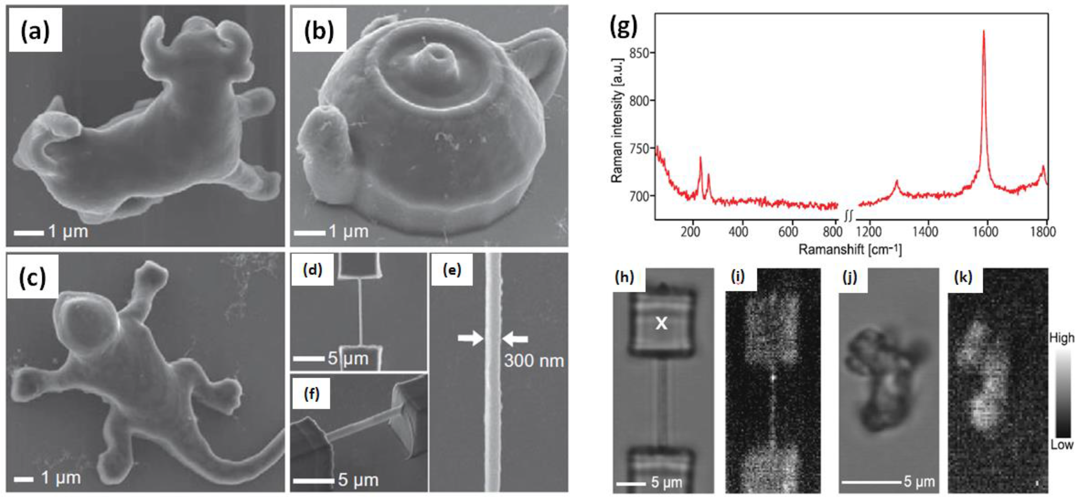
Figure 2.
(a) Representative scheme of the DLP 3D printing process and 3D hexagonal structure (thickness of 5 mm) containing, 0.1 wt. % CNTs as finished part; (b) Circuit-like structure built on an insulating base (PEGDA:PEGMEMA 1:1.5 wt/wt with brilliant green as colorant) with suspended elements containing 0.1 wt. % CNTs (30 × 50 mm. Copyright © 2017, with permission from Elsevier [77].

Figure 3.
(a) 3D-printed parts tend to display weak tensile properties in the y and z directions due to poor interlayer welding. To address this, the authors coated thermoplastic filament with a CNT-rich layer; the resulting 3D-printed part contains RF-sensitive nanofillers localized at the interface; (b) When a microwave field is applied, the interface is locally heated to allow for polymer diffusion and increased fracture strength [79].
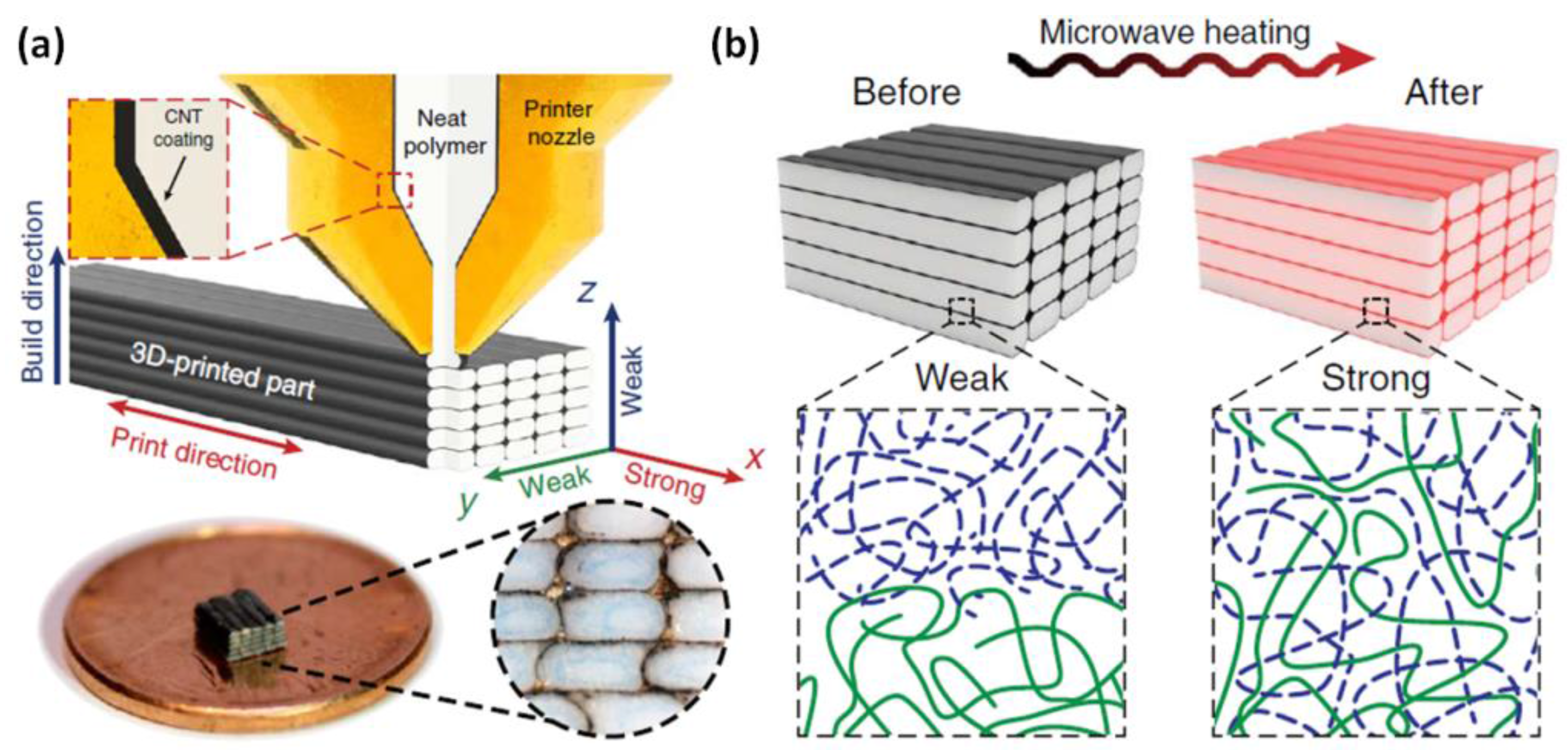
Figure 4.
(a) Tear tests are used to determine that (b) the fracture strength of 3D-printed PLA coupons is increased by 275% when CNT coatings and LIRF welding are applied; (c) A nanotube-coated, LIRF-welded PLA chain link printed in the z direction is able to support the weight of the co-author. This LIRF welding enables new, high-strength applications of additive manufacturing [79].

Figure 5.
Functional micro/nanostructures fabrication based on MTA composite resins by TPP lithography. Bent polyethylene terephthalate (PET) substrate (a) and SiO2/Si substrate (b) used for TPP fabrication with Au electrode patterns; (c–h) Scanning electron microscopy (SEM) micrographs of various functional micro/nanostructures including a microcoil inductor (c); a woodpile (d); a microgear (e); a micro-pyramid (f); a microcar (g) and a spiral-like photonic crystal (h). The laser power and scanning speed used in the TPP fabrication were 15 mW and 0.5 mm/s, respectively. Copyright © 2016, with permission from SPIE [80].

Figure 6.
(a) Viscosity as a function of shear rate and (b) storage and loss moduli as functions of ink shear stress. ((a), Inset) Histogram comparing viscosities of CNT inks with 7 wt. % A-MWNT and different PVP concentrations (0, 10, 17, 25 wt. %). The viscosity at a 10 s−1 shear rate increases gradually from 12.64 to 88.38 mPa·s; (c) Schematic diagram of 3D-printing process based on meniscus-guided printing. A 3D square MWNT microarchitecture (FE-SEM image) is printed by horizontally pulling a micronozzle filled with CNT ink (PVP-wrapped A-MWNT suspended in water), with water evaporating from the ink meniscus during the nozzle pulling. (d–f) FE-SEM images of 3D wall architectures with different shapes: (d) “3D” shaped wall (thickness (t) = 10 μm and height (h) = 24 μm); (e) Four-stair structure with orthogonal feature (t = 10 μm, h = 48 μm); (f) Three-dimensional cross-shaped structure with elliptical hollow feature (t = 10 μm, h = 40 μm). All scale bars are 20 μm. Reprinted (adapted) with permission from [82]. Copyright (2016) American Chemical Society.


Table 1.
Abbreviations and their elaborations.
| Abbreviations | Elaborations |
|---|---|
| AM | Additive manufacturing |
| 3DP | 3D printing |
| CNT | Carbon nanotubes (CNT) |
| SWCNTs | Single-wall carbon nanotubes |
| MWCNTs | Multi-wall carbon nanotubes |
| GO | Graphene oxide |
| CAD | Computer-aided design |
| RP | Rapid prototyping |
| FDM | Fused deposition modeling |
| SL | Stereolithography |
| MSL | Micro-stereolithography |
| DOPsL | Dynamic optical projection stereolithography |
| DW | Direct-write assembly |
| SLS | Selective laser sintering |
| SC-3DP | Solvent-cast 3DP |
| C-3DP | Conformal 3DP |
| TPP | Two-photon polymerization |
| DLP | Digital light processing |
| ABS | Acrylonitrile-butadiene-styrene |
| PLA | Poly(lactic acid) |
| PBT | Polybutylene terephthalate |
| PCL | Poly(caprolactone) |
| PEGDA | Poly(-ethylene glycol) diacrylate |
| PEGMEMA | Poly(ethylene glycol) methyl ether methacrylate |
| BAPO | Bis(2,4,6-trimethylbenzoyl)-phosphineoxide |
| PVP | Poly(vinylpyrrolidone) |
| CVD | Chemical vapor deposition |
| LDM | Liquid deposition modeling |
| CF | Carbon fiber |
| SEM | Scanning electron microscopy |
| MTA | Multi-walled carbon nanotube-thiol-acrylate |
| MSCs | Microsupercapacitors |
| DCM | Dichloromethane |
| HA | Hydroxyapatite |
| TPU | Polyurethane |
Table 2.
CNTs/polymer composites preparation using various additive manufacturing fabrication methods.
Table 2.
CNTs/polymer composites preparation using various additive manufacturing fabrication methods.
| Technique | Polymer | CNT Type | CNT Concentration | Potential Applications/Additional Information | Year Published | Ref. |
|---|---|---|---|---|---|---|
| Stereolithography (SLA) | Epoxy | MWCNTs | 0.05% (w/v) | Nanocomposites with high tensile and fracture stress | 2007 | [69] |
| Stereolithography (SLA) | Acrylic ester photopolymer | MWCNTs | 0.5% to 1.5% wt. % | Radar absorbing materials (RAM) and novel RAM structures | 2016 | [70] |
| Liquid deposition modeling (LDM) | Poly(lactic acid) (PLA) | MWCNTs | Not available (NA) | Conductive polymer-based 3D microstructures | 2015 | [71] |
| Solvent-cast 3D printing | Poly(lactic acid) (PLA) | MWCNTs | 5% | High electrical conductivity and an excellent sensitivity for low power consumption devices | 2015 | [72] |
| Two-photon polymerization (TPP) lithography | Acrylic photopolymer | SWCNTs | 0.01 wt.% | Functional applications in micro- and nano-electromechanical systems | 2013 | [73] |
| Fused deposition modeling (FDM) | Polybutylene terephtha-late (PBT) | MWCNTs (+ graphene) | ~ 0.5 wt. % | Sufficient mechanical strength, stiffness, and chemical resistance for user specific application | 2017 | [76] |
| Digital light processing (DLP) | PEGDA and PEGMEMA | MWCNTs | Up to 0.3 wt. % | Structure with high electrical properties applications | 2017 | [77] |
| Fused deposition modeling (FDM) | Acrylonitrile butadiene styrene (ABS) | CNTs (+ carbon fiber) | 0.5%, 1% and 3% | Comparative study between conventional injection molding and 3D printing | 2014 | [78] |
| Locally induced RF (LIRF) welding of 3DP parts | Feedstock polylactide (PLA) | MWCNTs | Up to 20 wt. % in the film | For the enhancements of 3D-printed weld strength | 2017 | [79] |
| Two-photon polymerization (TPP) lithography | Thiol-acrylate resins (MTA) | MWCNTs | 0.05, 0.1, 0.15 and 0.2 wt. % | Precise 3D printing for device applications | 2016 | [80] |
| A new/novel technique based on inkjet and extrusion based 3D printing | Poly(vinyl alcohol) (PVA) | MWCNTs | 70 wt. % of dispersion agent wt. in the ink | Microsupercapacitors (MSCs), energy storage devices | 2017 | [81] |
| Meniscus-guided printing | Polyvinylpyrrolidone (PVP) | MWCNTs | ~75 wt. % | Electronic components such as sensing transducers, emitters, and radio frequency inductors | 2016 | [82] |
| Solvent cast 3D printing method | Polylactic acid (PLA) | MWCNTs | UP to 40 wt. % | Scaffold structures as Liquid sensors | 2016 | [84] |
| Nozzle-deposition method/layer-by-layer dispensing | Hydroxyapatite (HA) and polycaprolactone (PCL) | MWCNTs | Up to 10 wt. % | Scaffold for bone regeneration | 2016 | [85] |
| Selective laser sintering (SLS) | Polyurethane (TPU) | MWCNTs | 0.1 to 1 wt. % | Flexible circuit, wearable devices, implantable devices, electronic skin, dielectric elastomer actuators | 2017 | [86] |
© 2017 by the author. Licensee MDPI, Basel, Switzerland. This article is an open access article distributed under the terms and conditions of the Creative Commons Attribution (CC BY) license (http://creativecommons.org/licenses/by/4.0/).
Share and Cite
MDPI and ACS Style
Ghoshal, S. Polymer/Carbon Nanotubes (CNT) Nanocomposites Processing Using Additive Manufacturing (Three-Dimensional Printing) Technique: An Overview. Fibers 2017, 5, 40. https://doi.org/10.3390/fib5040040
AMA Style
Ghoshal S. Polymer/Carbon Nanotubes (CNT) Nanocomposites Processing Using Additive Manufacturing (Three-Dimensional Printing) Technique: An Overview. Fibers. 2017; 5(4):40. https://doi.org/10.3390/fib5040040
Chicago/Turabian StyleGhoshal, Sushanta. 2017. "Polymer/Carbon Nanotubes (CNT) Nanocomposites Processing Using Additive Manufacturing (Three-Dimensional Printing) Technique: An Overview" Fibers 5, no. 4: 40. https://doi.org/10.3390/fib5040040
Note that from the first issue of 2016, this journal uses article numbers instead of page numbers. See further details here.