
Strong Light Localization and a Peculiar Feature of Light Leakage in the Negative Curvature Hollow Core Fibers


Fiber Optics Research Center of RAS, Moscow 119333, Russia
*
Author to whom correspondence should be addressed.
Fibers 2017, 5(4), 43; https://doi.org/10.3390/fib5040043
Submission received: 31 August 2017
/
Revised: 12 October 2017
/
Accepted: 9 November 2017
/
Published: 14 November 2017
(This article belongs to the Special Issue Fabrication of Special Optical Glass and Polymer Fibres)
Abstract
:In this paper we would like to continue a discussion started in our previous work and devoted to the mechanism of light localization in hollow core microstructured fibers with a noncircular core-cladding boundary. It has been shown in many works that, for waveguide microstructures with different types of core-cladding boundary shape, the positions of the transmission bands’ edges can be predicted by applying the well-known anti–resonant reflecting optical waveguide (ARROW) model. At the same time, the ARROW model cannot explain the strong light localization and guiding at high material loss inside the transmission bands which are observed in negative curvature hollow core fibers, for example. In this paper we want to clarify our previous findings and consider the light localization process from another point of view, namely, by comparing the light leakage process in waveguide microstructures with different shapes of the core-cladding boundary. The results are discussed based on the ARROW model and a new approach associated with the consideration of spatial dispersion occurring under the interaction of the air core mode with the core-cladding boundary.
1. Introduction
To date, hollow core microstructured fibers (HCMFs) have a rather long history [1]. They have opened new prospects in science and many practical applications such as nonlinear fiber optics [2], fiber gas lasers [3,4,5], high power laser delivery [6,7], and many others. There are three main types of HCMFs, namely, hollow core photonic crystal fibers (HC PCFs), Kagome lattice hollow core fibers, and, invented not so long ago, negative curvature hollow core fibers (NCHCFs). According to modern understanding of light guiding in these HCMFs, each of them has their own mechanism of light localization in the air core and corresponding specific optical properties.
For example, the light localization in HC PCFs is based on the conception of the ‘out of plane’ photonic band gap when two-dimensional photonic crystal cladding exhibits forbidden frequency ranges for the air core modes with a non-zero wavevector component β (propagation constant) directed along the fiber axis [1]. Silica HC PCFs have a rather complex structure of the photonic crystal cladding with a finite number of rows of air holes which determine the level of confinement loss. The width of the bandgaps is also determined by the lattice structure of the cladding, which is usually a circular array of air holes packed in a triangular arrangement. The photonic band gap mechanism of light localization is not required to guide light in Kagome lattice hollow core fibers [3]. The lattice of the fibers consists of fine silica webs arranged in a Kagome lattice and surrounded by air. According to modern understanding, the air core modes in hollow core Kagome lattice fibers are prevented from coupling to the cladding by the inhibited coupling (IC) mechanism of light localization [8]. To explain the IC guidance mechanism, the authors [8] drew an analogy with a well-known phenomenon in photonics called bound state in a continuum [9,10] and generalized this phenomenon to the process of light localization in Kagome lattice hollow core fibers. According to this point of view, the air core modes and cladding modes can propagate without strong interaction despite the same effective indices and, because of this, the air core modes are strongly inhibited from channeling out through the photonic crystal cladding. The authors [8] also generalized this point of view to so-called hypocycloid core-contour Kagome lattice hollow core fibers [11] and explained the strong light localization in them based only on the IC guidance mechanism [8]. According to the authors [8], the main factors affecting a loss reduction for the HE11 air core mode in the hypocycloid core-contour Kagome lattice hollow core fiber are determined by a weak overlap with silica at the core-cladding boundary (only tangent sections of the inner cups of the hypocycloid contour), a stronger transverse phase mismatch between the silica surround modes and the air core modes, and the fact that spatial overlap between the air core modes with connecting nodes is strongly reduced.
In contrast to HCMFs described above, NCHCFs donot have complicated photonic crystal cladding. The NCHCF claddings usually consist only of one row of silica glass capillaries or elements which are similar to ‘ice cream cones’ [12,13]. Despite this fact, light localization in silica glass NCHCFs is very strong and they can guide the light even in a mid-Infrared spectral range where the material loss of silica glass is very high and other types of HCMFs cannot guide [14]. At present, most authors consider the mechanism of light localization in NCHCFs based on the well-known anti – resonant reflecting optical waveguide anti–resonant reflecting optical waveguide (ARROW) mechanism [15]. In this case, the core-cladding boundary wall can be considered as a Fabry–Perot resonator which can reflect light very effectively in an antiresonant regime. In reality, the positions of the edges of the transmission bands in NCHCFs can be predicted by the ARROW model, but the strong light localization in the air core inside the transmission bands and light guiding at high material loss cannot be fully explained by this model. As was shown in our previous work [16], the ARROW model can be applied to describe the light localization in NCHCFs only when cladding capillaries are placed at a certain distance from each other. When cladding capillaries are located at a close distance from each other, or touch each other, light localization achieves the maximum value. In this case, the ARROW model can’t be applied to describe the process of light localization in the air core and the IC model can, in general terms, explain the main features of light localization in NCHCFs. This is a consequence of a special mechanism of light localization and leakage in NCHCFs which is not determined by optical properties of complicated photonic crystal cladding or antiresonant properties of the core-cladding boundary wall, but by the shape of the core-cladding boundary wall.
In [16], we showed that the degree of light localization in simplified polygonal shape HCMFs or NCHCFs strongly depends on a discrete rotational symmetry of the core-cladding boundary and corresponding distribution of the air core mode fields in the core-cladding boundary wall. In this paper, we intend to examine an interesting feature of light leakage in these HCMFs connected with the core-cladding boundary shape which can confirm our previous conclusions. This feature cannot be explained by the ARROW or IC model. We propose that this phenomenon be considered as a manifestation of spatial dispersion (diffraction) occurring under the interaction of the air core mode with the core-cladding boundary wall. Due to a periodic change of the core-cladding boundary shape in the azimuthal direction, the normal and tangential components of the transverse wave vector component become dependent on the value of the azimuthal angle and thus interrelated . The spatial dispersion (diffraction) can be modified in 2D or 3D photonic crystals when the dependence between the longitudinal component of the wavevector and its transverse component occurs for the propagation Bloch modes. This can lead to nontrivial spatial propagation effects such as self-collimation, for example [17]. The spatial dispersion for the transverse wavevector components of the air core modes in the vicinity of the core-cladding boundary wall leads to special distribution of the fields in this wall and, consequently, to nontrivial features of light leakage from the air core.
The paper is organized as follows: in Section 2, we analyze loss behavior for several waveguide microstructures depending on the value of an air core diameter and consider some data and conclusions drawn in our previous work [16]; in Section 3, major findings of the paper are presented; and, in Section 4, we discuss and analyze these results.
2. The Effect of the Core-Cladding Boundary Shape on the Light Leakage from the Air Core in Waveguide Microstructures with Different Shapes of the Core-Cladding Boundary
In this section, we consider the process of light leakage from idealized waveguide microstructures with various shapes of the core-cladding boundary walls. In [16], we calculated a waveguide loss for several polygonal microstructures depending on the wavelength in one of the transmission bands. As was shown, in the case of polygonal waveguide microstructures, the level of waveguide loss of the fundamental air core mode strongly depends on the air core mode field distribution in the core-cladding boundary wall. Square and triangular microstructures had a minimal loss level among other polygonal microstructures. At the same time, the negative curvature octagon microstructure had the minimum loss among all considered waveguide microstructures. The maximum waveguide loss was observed for a silica glass capillary with a normal electric field distribution in the capillary wall corresponding to the ARROW model. The effective mode area of the fundamental mode was the same for all waveguide microstructures.
Shown in Figure 1 are waveguide losses for fundamental air core modes depending on the value of air core diameters (calculated based on the area of an inscribed circle in each microstructure) for circular silica glass capillary, octagon, and square waveguides, as well as for a negative curvature microstructure with ten capillaries in the cladding. In order to isolate the impact of the core-cladding boundary shape on the light localization in the air core, all considered waveguide microstructures are located in an empty space. All waveguide microstructures are made of silica glass, and the thickness of the waveguide walls is 740 nm. The calculations were carried out at a wavelength of 1.03 µm in the center of the first transmission band. It is the first transmission band according to the ARROW model. It can be seen from Figure 1 that the maximum waveguide loss is achieved for a silica glass capillary. It is known that in the case of a glass capillary the waveguide loss value is proportional to , where Dcore is the air core diameter [18], and the waveguide loss for the silica glass capillary decreases according to this law in Figure 1. The waveguide loss dependencies for the octagon and square waveguides decrease faster with an increase in Dcore and in accordance with several other laws. The lowest waveguide loss is observed for a ten-capillary waveguide microstructure when cladding capillaries are located very close to each other, the distance between them being 2 µm. The law of waveguide loss dependence is also different from that for the silica glass capillary.
The waveguide loss dependencies for the octagon, square, and ten-capillary waveguide microstructures have resonant behavior which gives rise to a high loss in narrow ranges of values of the air core diameter. Also, there are sharp drops in the waveguide loss level in narrow ranges of values of the air core diameter. The origin of the resonant behavior can be explained by coupling between the air core mode and modes of the core-cladding boundary wall. Such interaction between the air core mode and the cladding mode can lead to the occurrence of Fano resonances in the loss spectrum [19]. In our opinion, the drops in the loss spectrum are connected with the occurrence of so-called bound states in the continuum, where the waveguide loss decreases dramatically when the air core mode interacts with some of the continuum modes [9,10]. Apparently, this phenomenon can be observed only when the waveguide microstructure is located in an empty space or when the supporting pipe in NCHCFs is located at a considerable distance from the cladding capillaries. We intend to discuss this phenomenon for polygonal waveguides and NCHCFs in greater detail in our future publication.
To understand the origin of the difference between the level of waveguide loss in the silica glass capillary and in other waveguide microstructures (Figure 1) it is necessary to consider the light leakage process from the waveguide microstructures and its dependence on the shape of the core-cladding boundary.
3. Results
In this Section we consider the behavior of the transverse component of the Poynting vector for the fundamental air core mode in all waveguide microstructures considered above. It is necessary to do so to understand the impact of a discrete rotational symmetry of the core-cladding boundary on the light leakage process from the air core. For our calculations, we have used the commercial packet Femlab 3.1 (Finite Element Method).
2D or 3D photonic crystals, i.e., materials with periodically spatially modulated refractive index on a wavelength scale, have such peculiar temporal dispersion properties as an appearance of bandgaps in the frequency domain [20]. In other words, the temporal dispersion can be described by the dependence for the propagation Bloch modes, where is a cyclical frequency and is a wavevector [16]. As it was pointed out in the Introduction, aside from the temporal dispersion in 2D or 3D photonic crystals there is also spatial dispersion (diffraction) when the longitudinal component of the wavevector depends on its transverse component [17]. In 2D or 3D photonic crystals, the spatial dispersion can be described by the dependence . The isofrequency lines of the propagation Bloch modes can be considered as the spatial dispersion curves . For a homogeneous medium, these dispersion curves are concentric circles, but for photonic crystals their shapes are distorted due to periodic modulation of the refractive index [17]. This can lead to unusual spatial phenomena in photonic crystals such as self-collimation, for example.
For polygonal waveguide microstructures and NCHCFs, there is also a periodically spatially modulated refractive index along the core-cladding boundary in the azimuthal direction (the origin of coordinates is in the center of the waveguide microstructures). The spatial dispersion should occur for the propagation air core modes in the vicinity of the core-cladding boundary and inside the core-cladding boundary wall.
In the silica glass capillary wall there is no spatial dispersion because all directions for the light leakage from the air core are equivalent. The longitudinal component of the wavevector β (propagation constant) and transverse component of the wavevector are uniquely connected by the value of the wavevector. The isofrequency lines are circles, as in the case of a homogeneous medium in the theory of photonic crystals [17]:
where n is a refractive index of the medium and α is the angle of incidence of the air core mode on the capillary wall. The interaction of the air core mode radiation with the core-cladding boundary wall is determined only by processes of transmission and reflection according to the ARROW model. For polygonal waveguide microstructures or NCHCFs with contiguous cladding capillaries, the transverse component of the wavevector in the vicinity of the core-cladding boundary wall is a sum of the tangential and normal components whose values and directions are dependent on the azimuthal angle ϕ:
This means that the shape of the isofrequency lines depend strongly on the value of the azimuthal angle at a considered point of the core-cladding boundary, and there is a spatial dispersion (diffraction) for the radiation of the air core modes propagating in the vicinity of or inside the core-cladding boundary wall. This diffraction should change light leakage from the air core and can lead to a deflection of the transverse component of the Poynting vector of the air core mode at certain sections of the core-cladding boundary. In this case, light interacts with the core-cladding boundary in a more complicated way and this interaction strongly depends on the shape of the core-cladding boundary wall; specifically, on its type of discrete rotational symmetry [16].
To analyze the light leakage process for the fundamental air core mode in all above-considered waveguide microstructures we examine a spatial distribution of the transverse component of the Poynting vector. In contrast to [8] where only the radial component of the Poynting vector was considered, we consider the transverse Poynting vector component projection on the direction of the radius vector drawn to a given point of the waveguide microstructure cross section from the origin of coordinates (the center of the waveguide microstructure):
where pzmax is the maximum value of the longitudinal component of the Poynting vector on the fiber cross section. The calculations were made for the value of Dcore = 50 µm (Figure 1).
In Figure 2, the distribution of is shown for the silica glass capillary; the streamlines for the transverse component of the fundamental air core mode Poynting vector of are presented by black lines. It can be seen that, at all points of the cross section, the values of are positive including the values in the vicinity of and inside the core-cladding boundary wall. The behavior of the streamlines of inside the capillary wall is completely described by the ARROW model when the air core mode leakage is defined only by the transmission and reflection processes at the inner and outer boundaries of the capillary wall. The transverse component of the fundamental air core mode Poynting vector is directed into the outer space at each point of the core-cladding boundary (Figure 2).
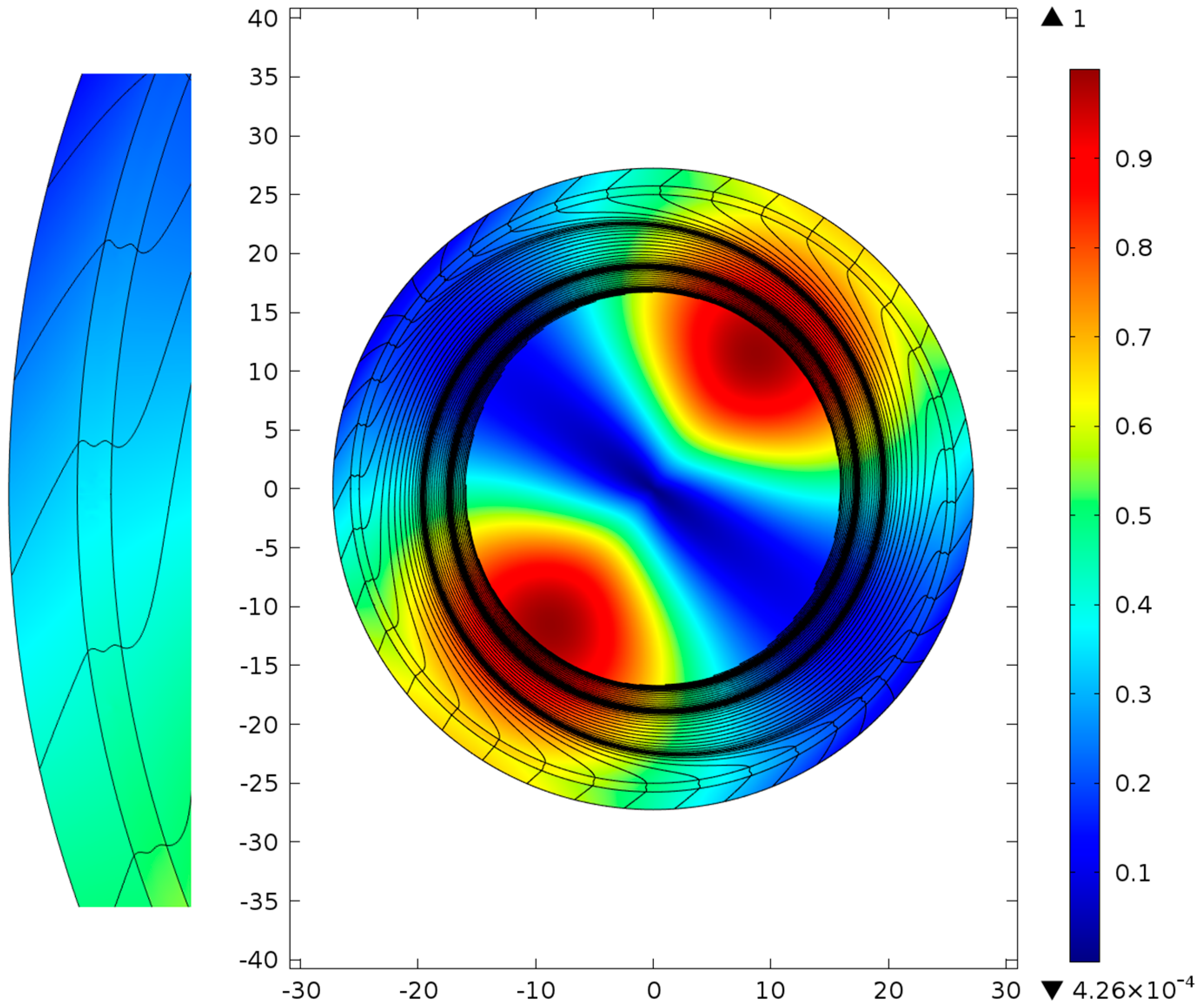
In the case of octagon waveguide microstructures (Figure 3), there is one more feature of light leakage behavior, namely, the distribution of the transverse Poynting vector projection on the radius vector has a periodic structure in the azimuthal direction and negative values along the core-cladding boundary wall. The streamlines of the transverse component of the Poynting vector also have unusual features which point to a different mechanism of the air core mode interaction with the core-cladding boundary wall (not all streamlines can be shown in the figures due to calculation restriction). It is clear that this mechanism of light leakage is not determined by the transmission and reflection of light in the vicinity of and inside the core-cladding boundary wall, but by a more complicated process which is accompanied by oscillations of values of and deflection of in the vicinity of the core-cladding boundary wall (Figure 3). The radiation of the air core mode can enter and leave the core-cladding boundary wall several times before leaving the microstructure.
This effect of the transverse component of the Poynting vector deflection and the oscillations of values of along the core-cladding boundary wall in the azimuthal direction is more pronounced in the case of the silica glass square waveguide microstructure (Figure 4). It can be seen from Figure 4 that the light leakage through the core-cladding boundary wall has the same unusual features as shown in Figure 3, namely, the distribution of the transverse Poynting vector projection on the radius vector in the vicinity of the core-cladding boundary wall has a periodic change of sign and deflections of from the original direction. Such behavior of the transverse component of the Poynting vector points to spatial dispersion for the air core mode fields in the vicinity of and inside the core-cladding boundary wall. This spatial dispersion (diffraction) leads to a different mechanism of light localization inside the transmission band and to a decrease in the level of waveguide loss for the octagon and square waveguide microstructures in comparison with the silica glass capillary (Figure 1).
The most interesting results can be obtained by examining a silica glass NCHCF. We considered a NCHCF with a cladding consisting of ten very closely located capillaries (Figure 5). It can be seen from Figure 5 that the values of and the streamlines of have the same behavior as in the case of the square waveguide microstructure but the distributions of are located only in the limited areas of the core-cladding boundary wall closest to the center of the waveguide microstructure. In this way, for NCHCF, the spatial dispersion (diffraction) allows the weakening of the interaction of the fundamental air core mode with the core-cladding boundary wall to the maximum value compared to other waveguide microstructures considered above. This leads to a very small level of waveguide loss for the fundamental air core mode: about 0.03 dB/km at a wavelength of 1.03 µm. In our previous paper [16], we called this mechanism of light localization ‘the local ARROW mechanism’, but now it is clear that the considered mechanism of light localization is different from the classical ARROW mechanism [15] (Figure 2). It is more suitable to call it a light localization mechanism based on the spatial dispersion occurring due to the azimuthal periodicity of the core-cladding boundary shape and the negative curvature of the core-cladding boundary wall. The effect of the negative curvature can fully manifest itself only in the case of very closely located cladding capillaries when the coupling between them is the strongest and they form a quasi-continuous core-cladding boundary. The ARROW mechanism of light localization (Figure 2) can be observed in NCHCFs if one increases the distance between the cladding capillaries, as was predicted in [16]. To demonstrate this effect let us consider two other NCHCFs with greater distances between cladding capillaries (Figure 6 and Figure 7).
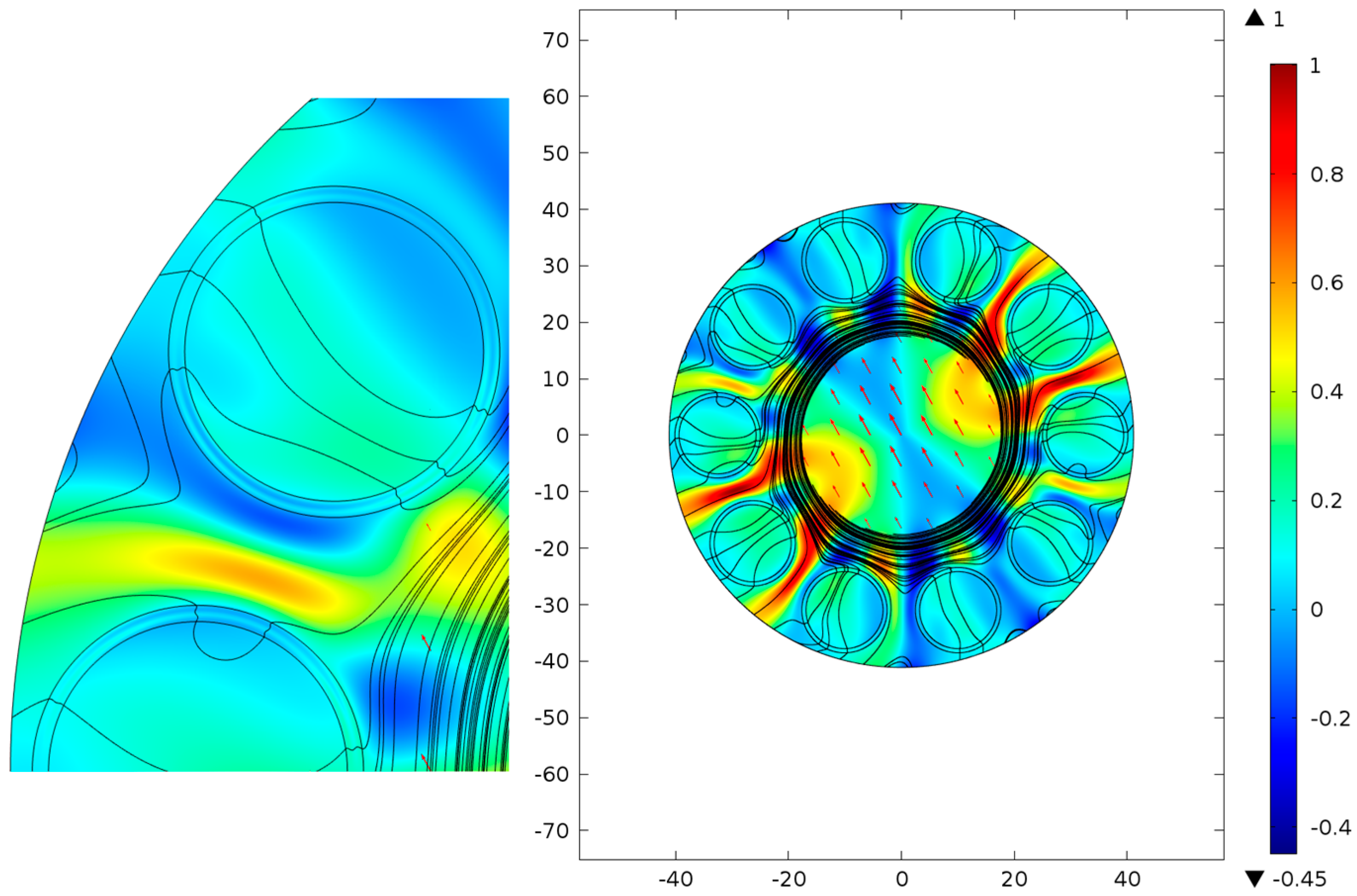
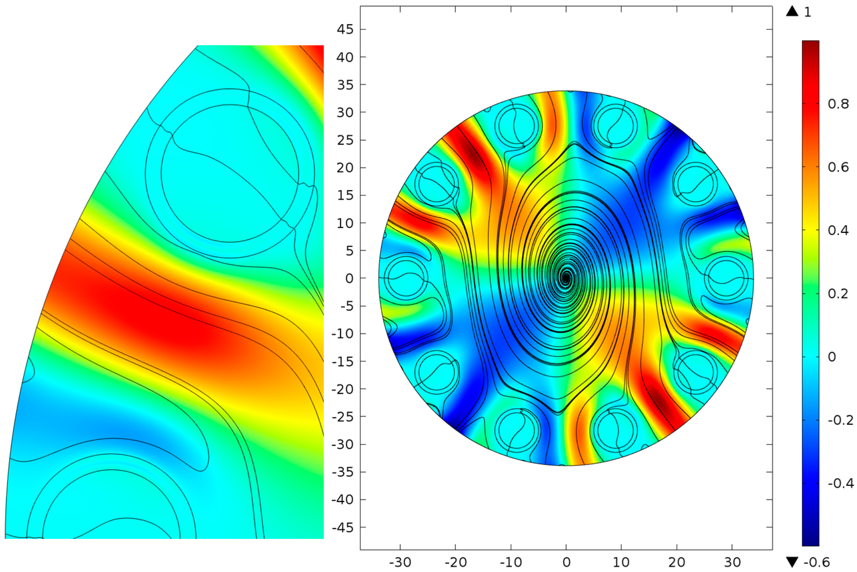
To obtain NCHCFs with greater distances between the cladding capillaries, their outer diameters were decreased but the wall thickness value remained the same. The distribution of and the streamlines of for the first NCHCF are shown in Figure 6. The coupling between the cladding capillaries is weaker than for the NCHCF shown in Figure 5 and each cladding capillary reflects the light as an individual scatterer [16]. As can be seen from the streamlines of (Figure 6), their behavior in the capillary walls is the same as in the case of the silica glass capillary (Figure 2). This means that the cladding capillaries reflect light according to the ARROW mechanism. At the same time, most air core mode radiation leaks out from the system due to space channels between the cladding capillaries (Figure 6). Moreover, it is seen from the distribution of that a part of the outgoing radiation makes complex loop motions and enters the system again as in the case of the square waveguide microstructure (Figure 4) and NCHCF (Figure 5). In our opinion, this occurs due to a certain discrete rotational symmetry of the cladding capillary arrangement. Due to this complex motion of the air core mode radiation in the transverse plane, the waveguide loss is not very high, and is about 0.3 dB/km at a wavelength of 1.03 µm. This effect will be discussed in more detail in our future publication.
The leakage becomes much more intense in the case of NCHF with a greater distance between the cladding capillaries (Figure 7) than in case of the NCHCF shown in Figure 6. The cladding capillaries also reflect and transmit the air core mode radiation according to the ARROW model but much more air core mode radiation leaks out through the space channels between them. In this case, the waveguide loss is about 740 dB/km at a wavelength of 1.03 µm. Nevertheless, the complex loop motion of the air core mode radiation in the transverse plane remains unchanged, which should decrease the waveguide loss level.
Additional simulations should be carried out to clarify the role of the supporting tube in the process of light leakage from the real NCHCFs and to determine the degree of influence of the rotational symmetry of the NCHCF cladding or the optical properties of a single cladding element on the waveguide loss level. Such simulations will be considered in our future publication.
4. Discussion
In this paper we briefly discussed the light localization mechanism and light leakage process in waveguide microstructures with a complicated shape of the core-cladding boundary (especially those with a specific type of discrete rotational symmetry of the cladding elements arrangement) and demonstrated its difference from the classical ARROW mechanism in the microstructures with a circle core-cladding boundary. A complicated shape of the core-cladding boundary leads to a complex distribution of the air core mode fields in the vicinity of and inside the core-cladding boundary wall in the azimuthal direction. This occurs due to a spatial dispersion (diffraction) for the air core modes of the waveguide microstructures, which also takes place in 2D or 3D photonic crystals for the propagation Bloch modes. In case of photonic crystals, this can lead to unusual propagation effects such as self-collimation and the disappearance of diffraction. For polygonal waveguide microstructures or NCHCFs, the transverse Poynting vector component changes its direction and deflects from the original direction into the outer space. These effects cannot be observed in the waveguides with a circular-shaped core-cladding boundary because the light localization in them is determined by the ARROW model, where only the optical thickness of the core-cladding boundary wall is taken into account. For this reason, the waveguide loss for waveguide microstructures with a polygonal shape of the core-cladding boundary or NCHCFs is lower than in the case of a circular core-cladding boundary shape when the air core diameter . Based on this fact, the conclusion may be drawn that it is not correct to call this mechanism of light localization the local ARROW mechanism [16], because the light reflection from the cladding capillaries according to the ARROW mechanism can be observed only for NCHCFs with non-contacting cladding capillaries separated by a sufficiently large distance. At the same time, the rotational symmetry of the cladding capillary arrangement plays an important role in the process of the air core modes localization even in NCHCFs with non-contacting cladding capillaries separated by a sufficiently large distance. All the above applies to light localization inside the transmission bands but not to the spectral regions near the band edges where the light leakage is determined by the conditions of transverse resonances in the core-cladding boundary wall or, in other words, by the classical ARROW mechanism.
To summarize, the obtained results confirm our conclusions made in [16] concerning an impact of the core-cladding boundary shape on the process of light localization in NCHCFs (pertaining to the commonality of light behavior in the polygonal waveguide microstructures and in NCHCFs with very closely located cladding capillaries). Nevertheless, the term ‘local ARROW mechanism of light localization’ should be reconsidered and defined based on a broader concept of the light localization mechanism in NCHCFs.
Acknowledgments
The reported study was supported by Russian Foundation for Basic Research (RFBR), research project N. 15-02-99688A.
Author Contributions
G.K.A. performed the calculations; A.D.P. analyzed the data and wrote the paper.
Conflicts of Interest
The authors declare no conflicts of interest.
References
- Russell, P. Photonic Crystal fibers. Science 2003, 299, 358–362. [Google Scholar] [CrossRef] [PubMed]
- Travers, J.C.; Chang, W.; Nold, J.; Joly, N.Y.; Russell, P.S.J. Ultrafast nonlinear optics in gas-filled hollow core photonic crystal fibers. JOSA B 2011, 28, A11–A26. [Google Scholar] [CrossRef]
- Couny, F.; Benabid, F.; Roberts, P.J.; Light, P.S.; Raymer, M.G. Generation and Photonic Guidance of Multi-Octave Optical-Frequency Combs. Science 2007, 318, 1118–1121. [Google Scholar] [CrossRef] [PubMed]
- Hassan, M.R.A.; Fei, Y.; Wadsworth, W.J.; Knight, J.C. Cavity-Based mid-IR fiber gas laser pumped by a diode laser. Optica 2016, 3, 218–221. [Google Scholar] [CrossRef]
- Gladyshev, A.V.; Kolyadin, A.N.; Kosolapov, A.F.; Yatsenko, Y.P.; Pryamikov, A.D.; Biryakov, A.S.; Bufetov, I.A.; Dianov, E.M. Efficient 1.9-µm Raman generation in a hydrogen-filled hollow-core fibre. Quantum Electronucs 2015, 45, 807–812. [Google Scholar] [CrossRef]
- Michieletto, M.; Lyngso, J.K.; Jakobsen, C.; Lægsgaard, J.; Bang, O.; Alkeskjold, T.T. Hollow-core fibers for high power pulse delivery. Opt. Express 2016, 24, 7103–7119. [Google Scholar] [CrossRef] [PubMed]
- Krylov, A.A.; Senatorov, A.K.; Pryamikov, A.D.; Kosolapov, A.F.; Kolyadin, A.N.; Alagashev, G.K.; Gladyshev, A.V.; Bufetov, I.A. 1.56-µm sub-microjoule femtosecond pulse delivery through low-loss microstructured revolver hollow-core fiber. Laser Phys. Lett. 2017, 14, 035104. [Google Scholar] [CrossRef]
- Debord, B.; Amsanpally, A.; Baz, A.; Maurel, M.; Blondy, J.M.; Hugonnot, E.; Scol, F.; Vincetti, L.; Gerome, F.; Benabid, F. Ultralow transmission loss in inhibited-coupling guiding hollow fibers. Optica 2017, 4, 209–217. [Google Scholar] [CrossRef]
- Marinica, D.C.; Borisov, A.G.; Shabanov, S.V. Bound States in the Continuum in Photonics. PRL 2008, 100, 183902. [Google Scholar] [CrossRef] [PubMed]
- Hsu, C.W.; Zhen, B.; Stone, A.D.; Joannopoulos, J.D.; Soljačić, M. Bound states in the continuum. Nat. Rev. Mater. 2016, 1, 16048. [Google Scholar] [CrossRef]
- Wang, Y.Y.; Wheeler, N.V.; Couny, F.; Roberts, P.J.; Benabid, F. Low loss broadband transmission in hypocycloid-core Kagome hollow-core photonic crystal fiber. Opt. Lett. 2011, 36, 669–671. [Google Scholar] [CrossRef] [PubMed]
- Pryamikov, A.D.; Biriukov, A.S.; Kosolapov, A.F.; Plotnichenko, V.G.; Semjonov, S.L.; Dianov, E.M. Demonstration of a waveguide regime for a silica hollow-core microstrucutred optical fiber with a negative curvature of the core boundary in the spectral region > 3.5 µm. Opt. Express 2011, 19, 1441–1448. [Google Scholar] [CrossRef] [PubMed]
- Yu, F.; Knight, J.C. Spectral attenuation limits of silica hollow core negative curvature fiber. Opt. Express 2013, 21, 21466–21471. [Google Scholar] [CrossRef] [PubMed]
- Kolyadin, A.N.; Kosolapov, A.F.; Pryamikov, A.D.; Biriukov, A.S.; Plotnichenko, V.G.; Dianov, E.M. Light transmission in negative curvature hollow core fiber in extremely high material loss region. Opt. Express 2013, 21, 9514–9519. [Google Scholar] [CrossRef] [PubMed]
- Litchinitser, N.M.; Abeeluck, A.K.; Headley, C.; Eggleton, B.J. Antiresonant reflecting photonic crystal optical waveguides. Opt. Lett. 2002, 27, 1592–1594. [Google Scholar] [CrossRef] [PubMed]
- Pryamikov, A.D.; Alagashev, G.K.; Kosolapov, A.F.; Birukov, A.S. Impact of core-cladding boundary shape on the waveguide propaerties of hollow core microstructured fibers. Laser Phys. 2016, 26, 125104. [Google Scholar] [CrossRef]
- Maigyte, L.; Gertus, T.; Peckus, M.; Trull, J.; Cojocaru, C.; Sirutkaitis, V.; Staliunas, K. Signatures of light-beam spatial filtering in a three-Dimensional photonic crystal. Phys. Rev. A 2010, 82, 043819. [Google Scholar] [CrossRef]
- Zheltikov, A. Colors of thin films, antiresonant phenomena in optical systems, and the limiting loss of modes in hollow optical waveguides. Physics-Uspekhi 2008, 51, 591–600. [Google Scholar] [CrossRef]
- Amsanpally, A.; Debord, B.; Alharbi, M.; Ilinova, E.; Vincetti, L.; Gerome, F.; Benabid, F. Fano resonances in inhibited coupling Kagome fiber. In Proceedings of the CLEO’2015, San Jose, CA, USA, 10–15 May 2015. [Google Scholar]
- John, S. Strong localization of photons in certain disordered dielectric superlattices. Phys. Rev. Lett. 1987, 58, 2486–2489. [Google Scholar] [CrossRef] [PubMed]
Figure 1.
Waveguide loss dependence on the value of the air core diameter for a silica glass capillary (red), a silica glass octagon waveguide (green), a silica glass square waveguide (black), and a silica glass negative curvature microstructure with ten capillaries in the cladding (blue).
Figure 1.
Waveguide loss dependence on the value of the air core diameter for a silica glass capillary (red), a silica glass octagon waveguide (green), a silica glass square waveguide (black), and a silica glass negative curvature microstructure with ten capillaries in the cladding (blue).
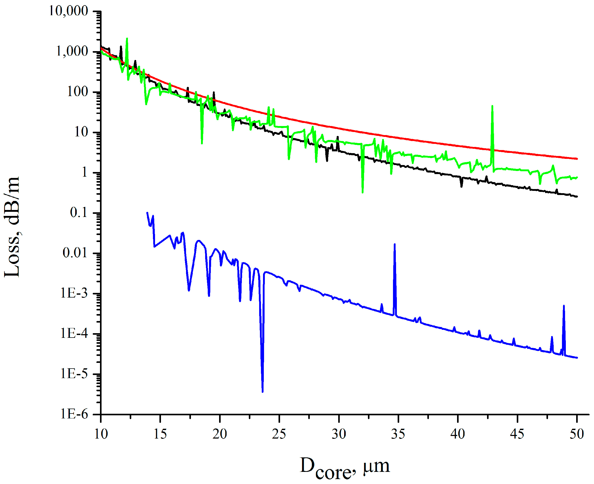
Figure 2.
Distribution of the transverse Poynting vector component projection on the radius vector direction in the silica glass capillary cross section. The streamlines for the transverse component of Poynting vector (black lines).
Figure 2.
Distribution of the transverse Poynting vector component projection on the radius vector direction in the silica glass capillary cross section. The streamlines for the transverse component of Poynting vector (black lines).

Figure 3.
Distribution of the transverse Poynting vector component projection on the radius vector direction in the silica glass octagon waveguide microstructure cross section. The streamlines for the transverse component of Poynting vector (black lines).
Figure 3.
Distribution of the transverse Poynting vector component projection on the radius vector direction in the silica glass octagon waveguide microstructure cross section. The streamlines for the transverse component of Poynting vector (black lines).
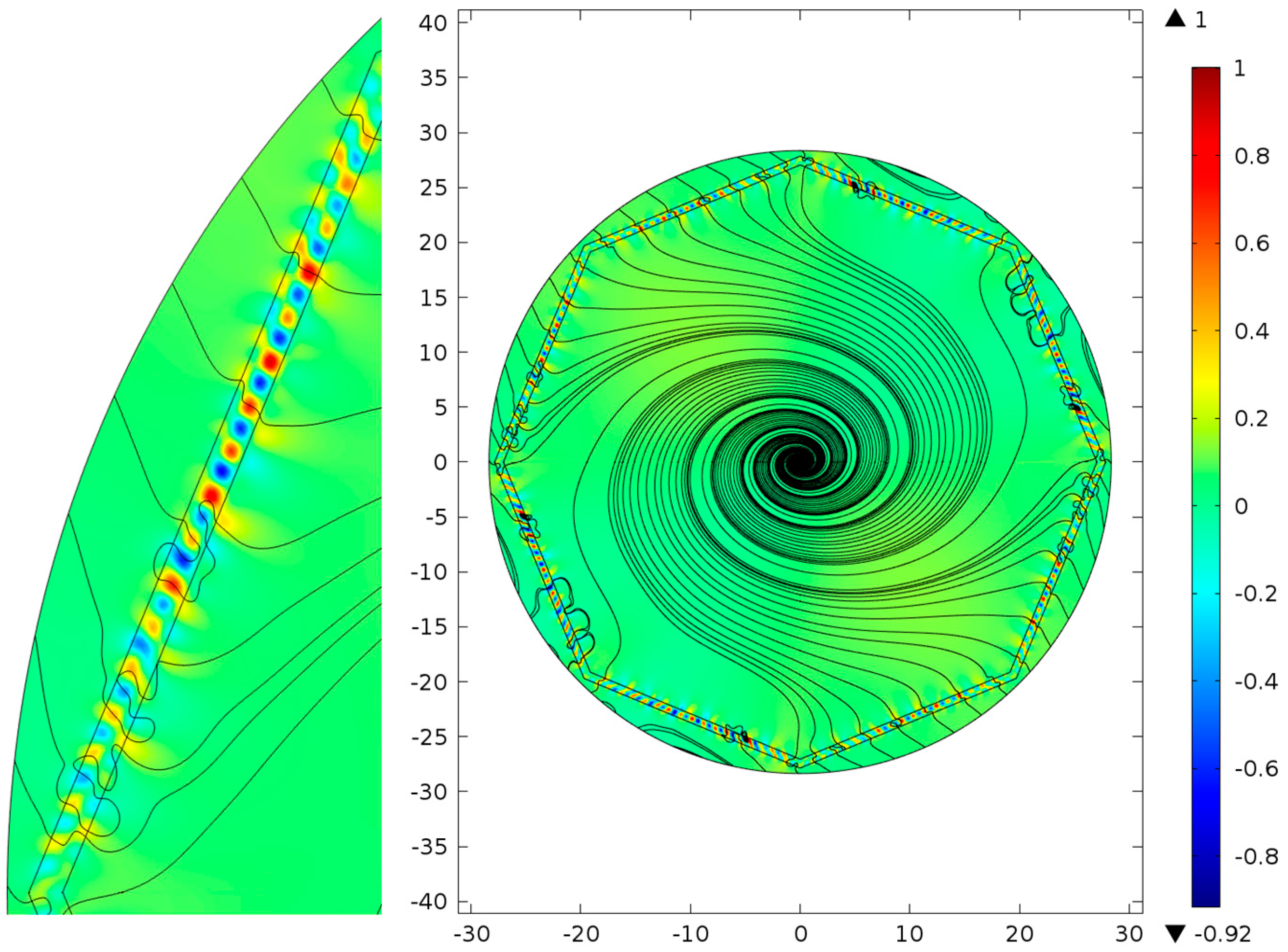
Figure 4.
Distribution of the transverse Poynting vector component projection on the radius vector direction in the silica glass square waveguide microstructure cross section. The streamlines for the transverse component of Poynting vector (black lines).
Figure 4.
Distribution of the transverse Poynting vector component projection on the radius vector direction in the silica glass square waveguide microstructure cross section. The streamlines for the transverse component of Poynting vector (black lines).
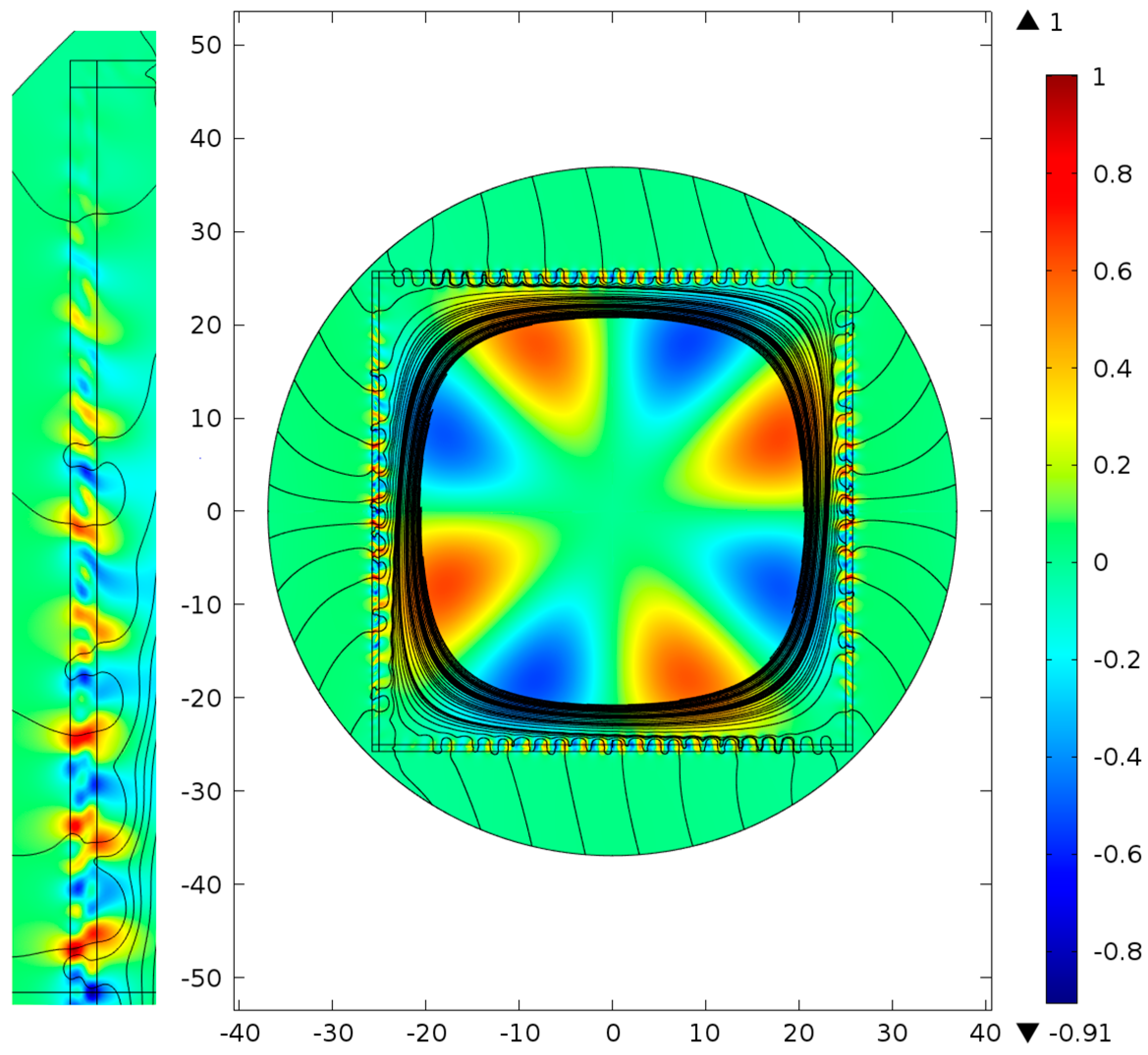
Figure 5.
Distribution of the transverse Poynting vector component projection on the radius vector direction in the cross section of a silica glass negative curvature hollow core fiber (NCHCF) with ten very closely located cladding capillaries. The streamlines for the transverse component of Poynting vector (black lines).
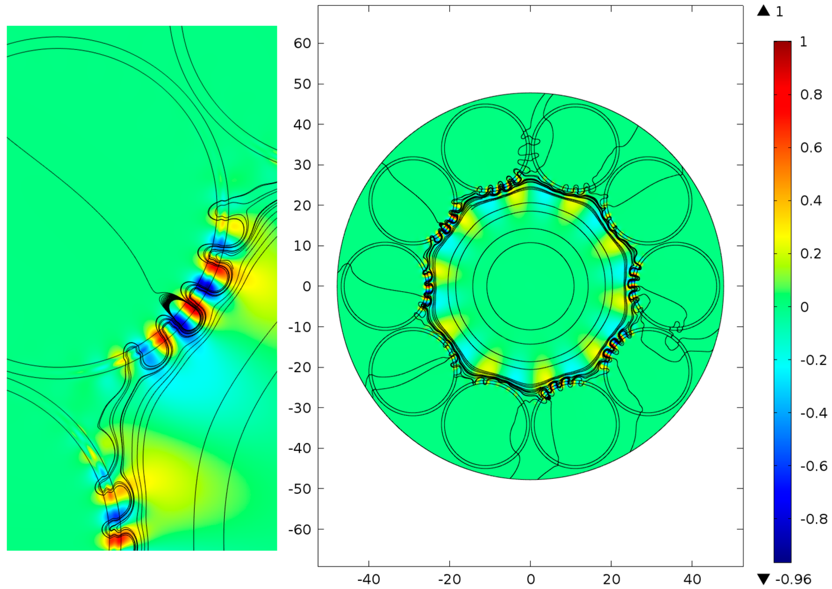
Figure 6.
Distribution of the transverse Poynting vector component projection on the radius vector direction in the cross section of a silica glass NCHCF with ten non-contacting cladding capillaries. The streamlines for the transverse component of Poynting vector (black lines).
Figure 6.
Distribution of the transverse Poynting vector component projection on the radius vector direction in the cross section of a silica glass NCHCF with ten non-contacting cladding capillaries. The streamlines for the transverse component of Poynting vector (black lines).

Figure 7.
Distribution of the transverse Poynting vector component projection on the radius vector direction in the cross section of a silica glass NCHCF with ten non-contacting cladding capillaries. The streamlines for the transverse component of Poynting vector (black lines).
Figure 7.
Distribution of the transverse Poynting vector component projection on the radius vector direction in the cross section of a silica glass NCHCF with ten non-contacting cladding capillaries. The streamlines for the transverse component of Poynting vector (black lines).
© 2017 by the authors. Licensee MDPI, Basel, Switzerland. This article is an open access article distributed under the terms and conditions of the Creative Commons Attribution (CC BY) license (http://creativecommons.org/licenses/by/4.0/).
Share and Cite
MDPI and ACS Style
Pryamikov, A.D.; Alagashev, G.K. Strong Light Localization and a Peculiar Feature of Light Leakage in the Negative Curvature Hollow Core Fibers. Fibers 2017, 5, 43. https://doi.org/10.3390/fib5040043
AMA Style
Pryamikov AD, Alagashev GK. Strong Light Localization and a Peculiar Feature of Light Leakage in the Negative Curvature Hollow Core Fibers. Fibers. 2017; 5(4):43. https://doi.org/10.3390/fib5040043
Chicago/Turabian StylePryamikov, Andrey D., and Grigory K. Alagashev. 2017. "Strong Light Localization and a Peculiar Feature of Light Leakage in the Negative Curvature Hollow Core Fibers" Fibers 5, no. 4: 43. https://doi.org/10.3390/fib5040043
Note that from the first issue of 2016, this journal uses article numbers instead of page numbers. See further details here.