Restrained Shrinkage Cracking of Fiber-Reinforced High-Strength Concrete


1
Department of Civil Engineering, Campus University, University of Guilan, Rasht 4199613776, Iran
2
Department of Civil Engineering, Technical Faculty, University of Guilan, Rasht 4199613776, Iran
3
School of Architecture and Built Environment, The University of Newcastle, Callaghan, NSW 2308, Australia
4
Department of Civil Engineering, Institute of Higher Education Deylaman, Lahijan 441451174, Iran
*
Author to whom correspondence should be addressed.
Fibers 2018, 6(1), 12; https://doi.org/10.3390/fib6010012
Submission received: 7 December 2017
/
Revised: 26 January 2018
/
Accepted: 1 February 2018
/
Published: 19 February 2018
(This article belongs to the Special Issue Recent Advancements in Fiber Reinforced Concrete And its Applications)
Abstract
:Concrete shrinkage and volume reduction happens due to the loss of moisture, which eventually results in cracks and more concrete deformation. In this study, the effect of polypropylene (PP), steel, glass, basalt, and polyolefin fibers on compressive and flexural strength, drying shrinkage, and cracking potential, using the ring test at early ages of high-strength concrete mixtures, was investigated. The restrained shrinkage test was performed on concrete ring specimens according to the ASTM C1581 standard. The crack width and age of restrained shrinkage cracking were the main parameters studied in this research. The results indicated that the addition of fiber increases the compressive strength by 16%, 20%, and 3% at the age of 3, 7, and 28 days, respectively, and increases the flexural toughness index up to 7.7 times. Steel and glass fibers had a better performance in flexural strength, but relatively poor action in the velocity reduction and cracking time of the restrained shrinkage. Additionally, cracks in all concrete ring specimens except for the polypropylene-containing mixture, was developed to a full depth crack. The mixture with polypropylene fiber indicated a reduction in crack width up to 62% and an increasing age cracking up to 84%.
1. Introduction
Concrete is known as one of the most applicable building materials all across the world. Its economy, the accessibility of its components, its suitable strength under different environmental conditions, and its high compressive strength are among the desired factors of concrete as a construction material [1,2,3]. Over the last several years, the concrete industry has experienced growth and development, which has led to the generation and development of concretes with high quality and applicability, such as high-performance concrete (HPC) and high-strength concrete (HSC) [4]. Nevertheless, concrete is weak against tensile strength and high strain, which can be compensated to a certain extent with reinforcement or fibers [5,6,7].
In recent years, fiber-reinforced concrete (FRC) has received considerable attention in civil engineering infrastructures such as pavements, bridges, tunnels, slabs, airports, shelters, and explosive storages. In this regard, concrete’s low tensile strength and brittleness, the high length-to-diameter ratio of fibers, and the distributed and dispersed concrete volume have been taken into consideration in recent decades. It is worth mentioning that mixtures containing fibers (steel) or reinforced concrete (RC) corrode and deteriorate (the load carrying capacity decreases) due to exposure to corrosive environments (chloride or sulfate conditions) [8]. This issue leads to the growth and development of micro- or macro-cracks, resulting in a decreased service life and/or durability due to the increased in water penetration, chloride ions, or carbonation. At this time and age, RC structure deterioration has caused the development of new and innovative materials and methods for structural rehabilitation and strengthening, as replacement of structures would be very costly and is thus prohibitive [9,10].
Employing fibers in concrete and cement-based composites, in order to increase toughness and ductility in post-crack regions, have seen considerable growth. The collapse and destruction of concrete is highly dependent on macro- or micro-crack formation under loading or environmental effects [11,12,13,14,15]. Thermal and humidity changes in cement paste lead to micro-crack formation that concentrates on coarse aggregate surface. In addition, more loading and environmental problems lead to more micro-cracks in concrete. Applying different fibers is an influential factor in crack development as well as in improving energy absorption and concrete toughness, which can lessen the possibility of concrete structure failure, especially in regions under cyclic or seismic loads [16]. Using fibers plays a key role in spalling, shrinkage, or thermal crack reduction as a replacement of thermal reinforcement. Furthermore, the presence of supplementary cementitious material (SCM) such as silica fume and fly ash, as well as the shape, size, type, volume, and fiber distribution pattern, are influential factors in concrete’s technical and economic efficiency. A wide spectrum of fibers with various physical, mechanical, and chemical properties are used for cementitious matrix reinforcement. Among accessible and applicable fibers in cementitious composites, steel, polypropylene (PP), glass carbon, and basalt fibers have been taken into account [17,18,19]. Figure 1 shows a schematic of fiber’s effect on the concrete fracture process under tensile loading.
In general, shrinkage is divided into four categories: shrinkage at early ages (polyolefin or capillary shrinkage), autogenous shrinkage, carbonation shrinkage, and drying shrinkage. Shrinkage at early ages in fresh concrete occurs due to a humidity exchange from surface to environment (by evaporation) and mass exchange through concrete to its surface. Polyolefin shrinkage at initial hours is measured after casting that is preventable by optimization of the mix design and suitable curing. Interactions between hardened cement paste and carbon dioxide lead to carbonation shrinkage [20,21]. Volume reduction due to this phenomenon occurs slowly in the surrounding area, such that it is inappreciable compared to drying shrinkage. Drying shrinkage occurs due to humidity exchange arising from relative humidity changes between environment and concrete. The latter case includes the majority of volume changes due to shrinkage in high- and middle-strength concretes. For this reason, this type of shrinkage is specifically studied in this research [22,23,24].
Extensive research has been carried out on the effect of various fiber types such as natural (organic) and artificial (inorganic) fibers on concrete. The first trial for concrete reinforcement by employing steel fibers was conducted by Baston and Ramualdiin in 1960 in the US [25]. After that, many studies and industrial applications on steel-fiber-reinforced concrete (SFRCP) and other fibers were performed to improve mechanical properties and durability. Based on the previous results, four main factors are influential in fibrous cementitious composites bearing capacity and strength: matrix quality, dimensions ratio, volume fraction, and bond strength (matrix–fiber interface). Vandewalle [26] studied the hybrid fiber-reinforced composites with different lengths and fiber concentrations. Results from measured crack opening displacement showed that short fibers are more efficient in regions with small crack openings, while long fibers provide good ductility in wide cracks. Short and long fibers lead to micro- or macro-crack bridging, respectively, thus resulting in an enhanced ultimate strain and post-crack bearing capacity. Fiber rupture in a cementitious matrix is caused by elongation (tearing) or pull-out [27].
In recent years, next-generation polyolefin fibers based on polypropylene show improved performance. Their diameter and length yield new application possibilities. A couple of studies have been performed to assess these fibers and their effect on concrete. Some studies have evaluated the shrinkage of cementitious matrices containing natural fibers such as chopped coconut and sisal fibers. Moreover, the effect of curing conditions, the materials ratio, and the different additives including chemical or inorganic materials (silica fume, fly ash, and slag) on the FRC shrinkage was investigated. It is reported that an addition of 0.2% volume fraction of sisal fibers in cementitious mortar leads to reduced polyolefin shrinkage. Additionally, the presence of fibers can increase the initial cracking time of restrained shrinkage and control crack growth effectively at the early age of cementitious composites [28]. A few studies concern the impacts of the polypropylene fiber on drying shrinkage of concrete [29,30,31]. The results indicated that the polypropylene fiber can significantly reduce the autogenous and total shrinkage of concrete.
Mostofinejad and Hatami [32] studied the effects of using polypropylene fibers on cracking caused by concrete shrinkage and workability. The results showed that increased fiber content and length considerably reduces polyolefin shrinkage crack surfaces up to 86% compared to non-fiber specimens. Tassew and Lubell [33] assessed the mechanical properties of glass fiber containing concrete. The results indicated that adding fibers had no drastic effect on compressive strength or elasticity module but considerably increased the flexural or direct shear strength. Saghi and Delbari [34] reported the impact of polyolefin fibers and concrete strength on cracking volume caused by polyolefin shrinkage in concrete slabs. The results showed that increased fiber content from 2 to 3% decreases the crack surface of polyolefin shrinkage up to 98%. Not only does the higher fiber content decrease the crack width, but it also increases the time required for crack generation on the concrete surface, respectively. In one paper, entitled “Prediction Method of Drying Shrinkage Crack in Reinforced Concrete Walls,” Lee and Seo [35] showed that “crack width is heavily influenced by concrete compressive strength, bars diameter, and its ratio but is barely influenced by drying shrinkage, restrain ratio, wall length, or creep coefficient.” The number of cracks and their predicted shrinkage width were close to the obtained results from the experimental works.
A review on the existing literature on fiber-reinforced high-strength concrete (FRHSC) reveals the fact that limited studies focus on the risk of cracking under restrained conditions for such concrete at early ages. Given the increasing interest in using FRHSC as a replacement for normal strength concrete in structural applications and construction of transportation infrastructure, there is a need to study the performance of concrete made of various fibers. The aim of the current research was to study the effect of different fibers on early age shrinkage, compressive strength, and the flexural strength of high-strength concrete (HSC). The studied parameters are width and type of cracks, as well as cracking age arising from restrained shrinkage. Concrete mixtures containing 0.1% volume fraction fibers with a 0.38 water to cementitious material ratio were used.
2. Experimental Program
2.1. Materials
In this research, Type I 42.5 Portland cement (with a specific gravity of 3.15 g/cm3 and specific surface of 3.19 m2/g) conforming to the requirements of ASTM C150 [37] was used. The supplementary material included silica fume (with a specific gravity of 2.2 g/cm3 and specific surface of 21.2 m2/g) conforming to the requirements of ASTM C1240 [38]. Chemical compositions of the cementitious materials are given in Table 1. The aggregates were composed of naturally crushed coarse aggregates, with a specific gravity of 2.67 g/cm3 and 19 mm nominal maximum size, and washed natural sand with a specific gravity of 2.61 g/cm3. Figure 2 shows the grain size of the aggregates consumed. In this research, five different types of fibers were used: polypropylene, steel, glass, basalt, and polyolefin with a 0.1% volume of concrete mixture. Table 2 shows the characteristics of the fibers.
2.2. Concrete Mixtures
In this study, six concrete mixtures consisting of a control specimen and five fibrous concretes with a water-to-cement ratio of 0.38 were designed. Additionally, 10% of cement by weight was replaced by silica fume. Due to the low water-to-cement ratio, a P10-3R0 polycarboxilate-based superpolyolefinizer additive was used. Mixture details are given in Table 3.
Concrete mixes were cast into molds after workability testing, and they were then coated with a polyolefin cover to prevent the initial moisture vapor. After 24 h, the concrete samples were demolded and cured in a water tank at normal temperature until testing day (Figure 3).
2.3. Testing Procedure
Unlike workability assessment of ordinary concrete, in which the amount of concrete slump is measured after the lifting of the Abrams cone, in the fibrous concretes, the concrete flow time in a reverse Abrams cone under the external vibration is measured. This test was carried out according to ASTM C 995 [39].
The compressive strength of concrete mixtures was evaluated using cubic samples with a dimension of 150 mm × 150 mm × 150 mm according to BS EN 12390-3 [40] at ages of 3, 7, and 28 days. The loading speed used in this test was 1350 N/s. The average of three samples were reported as the result of compressive strength.
Flexural strength test with a loading speed of 0.5 mm/s in the mid-span of the four-point beams, according to ASTM C1609 [41], was performed on prismatic specimens of 100 × 100 × 500 mm at 28 days. The distance between supports was 400 mm, as shown in Figure 4. Toughness is the property of a material that expresses its resistance to the rupture under stresses. According to the literature [42], flexural toughness is defined as ratio of the absorbed energy (area under the displacement curve during the flexural test) to the sample cross-section, which can be calculated according to Equation (1):
where b is the cross-section area of the prism sample in (mm) and h is the depth of the cross-section of the prism sample in (mm).
The restrained shrinkage test was performed according to ASTM C 1581 [43]. Accordingly, concrete specimens were made in the form of a ring with a height of 150 mm, an inner diameter of 33 mm and an outer diameter of 40.6 mm (Figure 5). In Figure 5, details of the concrete ring specimen are shown. Concrete rings were placed on a waterproof plate (made of polyolefin). After 24 h, outer steel rings were demolded and the upper part of the concrete rings were covered with paraffin wax to prevent moisture evaporation. To measure the steel ring strain, two strain gauges were installed in the middle of the steel ring height in opposite directions. A data logger was used to continuously record the data. The process of measuring the shrinkage of concrete rings is shown in Figure 6. The shrinkage of concrete rings was measured right after demolding. Due to the high dependence of shrinkage to the environmental factors such as the temperature and humidity in the early ages, concrete rings were kept in a room with a constant temperature of 22 °C and a humidity of 60%, which were constantly monitored in environmental conditions.
A high quality microscope was applied for measuring crack widths in concrete rings. The apparatus operates by an adjustable lamp unit, and the image is focused by turning a knob. Its magnification and accuracy were 40× and 0.01 mm, respectively.
3. Results and Discussion
3.1. Fresh Concrete Workability
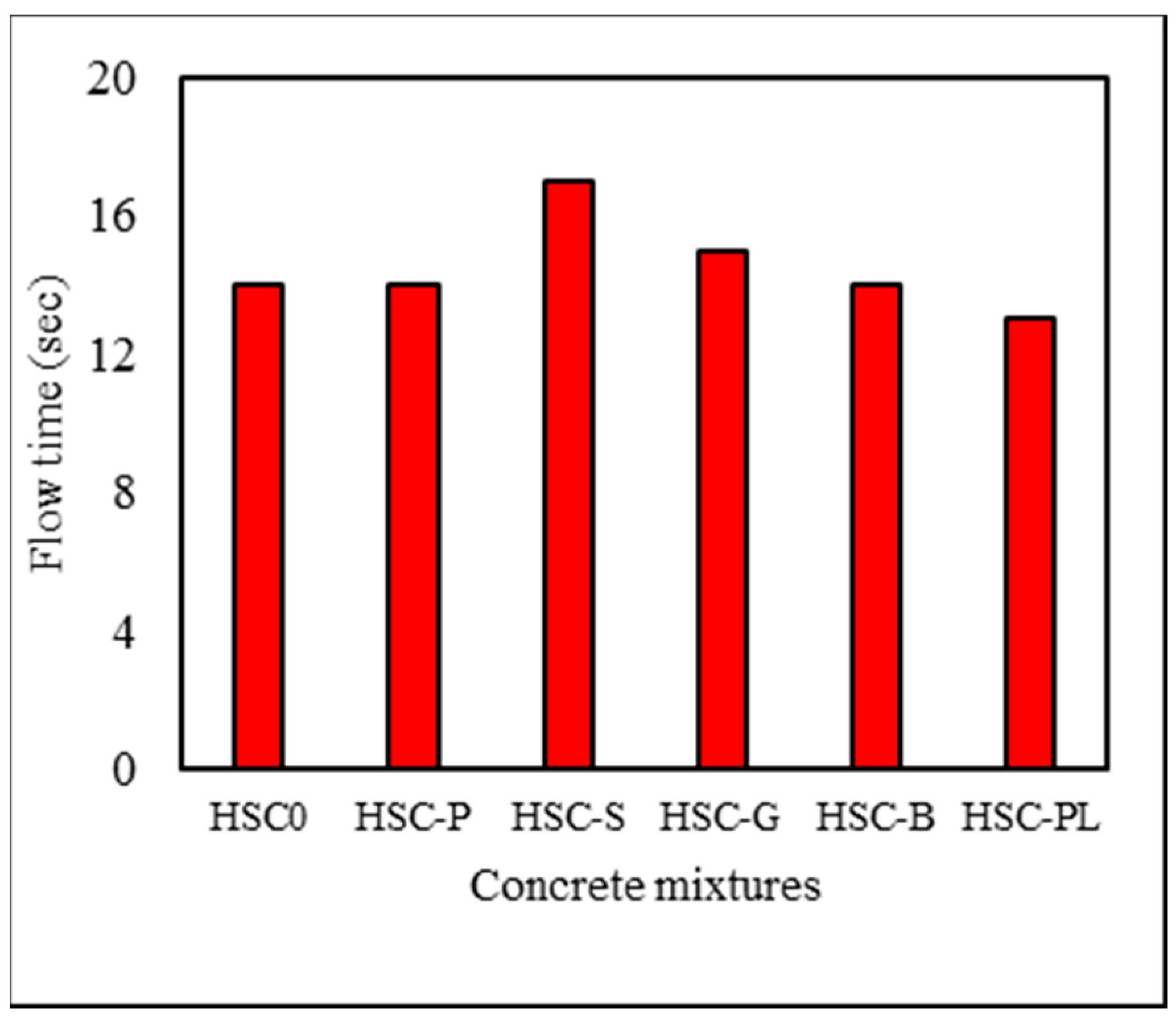
The way fibers are added to concrete mixture affects its balling or clumping. In order to reduce these effects, fibers were mixed with aggregate before adding water, so that after splitting cubic specimens with an age of 1 day, and fibers were favorably dispersed in the cementitious matrix volume. Flow times of each mixture are given in Figure 7. The addition of fibers had no considerable effect on flow time. In mixtures containing steel fibers, flow time showed minimal rise-up. The target slump was 25 mm, which correlates to a flow time of 15 s.
3.2. Compressive Strength
Compressive stress testing was performed at 3, 7, and 28 days, and the results are given in Figure 8. It was observed that the compressive strength of the fibrous concrete at early ages increased up to 16% (HSC-G, 3 days) and 20% (HSC, 7 days) respectively, compared to control concrete, which increased up to 3% by 28 days. This shows the positive effect of fibers at early ages. Despite the need for high-strength acquisition at early ages in the above-mentioned cases, using fibers was positively efficient. At 7 days, the strength of all mixtures (except for HSC-P) was higher than that of the control concrete. It seems that the matrix–fiber interface bond quality was weak, which led to a drop in strength. At 28 days, the polyolefin-fiber-containing mixture dropped in strength. After cubic specimen failure, it was observed that the balling effect in some portions blocked a smooth stress distribution and an optimal stabilization.
3.3. Flexural Strength
Flexural strength testing was performed on concrete mixtures at 28 days, and the results are given in Table 4. Load–deflection curves are shown in Figure 9. The fibrous concrete exhibited optimal behavior and performance compared to ordinary concrete under bending. According to the volumetric fiber content used, the main aim was to improve concrete cracking at early ages. The flexural strength of fibrous specimens was 22% higher than control specimens, with HSC-S being the highest strength. Fibers with higher stiffness (steel or basalt) exhibited the highest strength. In this test, after loading, two rupture modes emerged: in the first mode, for fibers with low tensile strength, rupture occurred right after fibers tensile rupture; in the second mode, specimens exhibited load–demanding behavior after the first tensile crack. Figure 10 shows steel fiber pull-out and fiber bridging. In Figure 9, except for the steel-fiber-containing mixture, no flexural prismatic exhibits post-crack behavior, which could be explained by the low fiber content. Figure 11 illustrates the prism specimens with or without fibers after flexural loading. Flexural toughness and absorbed energy are the most important phenomena that measure the fibrous concretes’ post-crack strength. In this study, the control of fibrous prism specimen splitting and toughness measurement was not possible. Only the toughness of steel-fiber-containing mixtures was measured, which exhibits post-crack behavior. Table 4 shows the results of flexural toughness absorbed energy in concrete mixtures.
3.4. Shrinkage
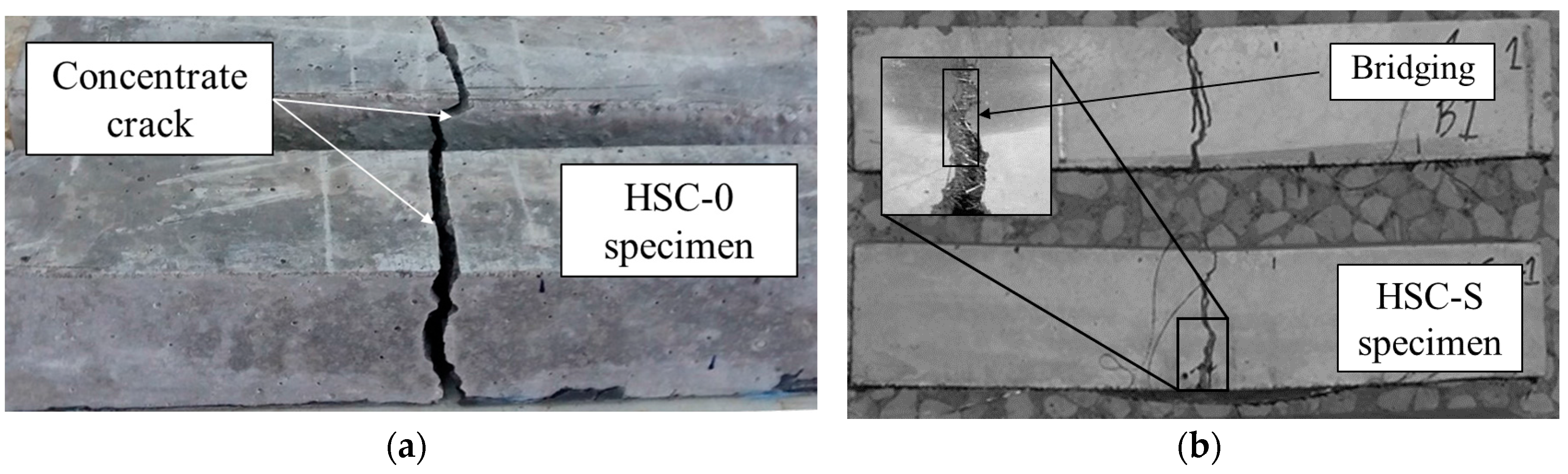
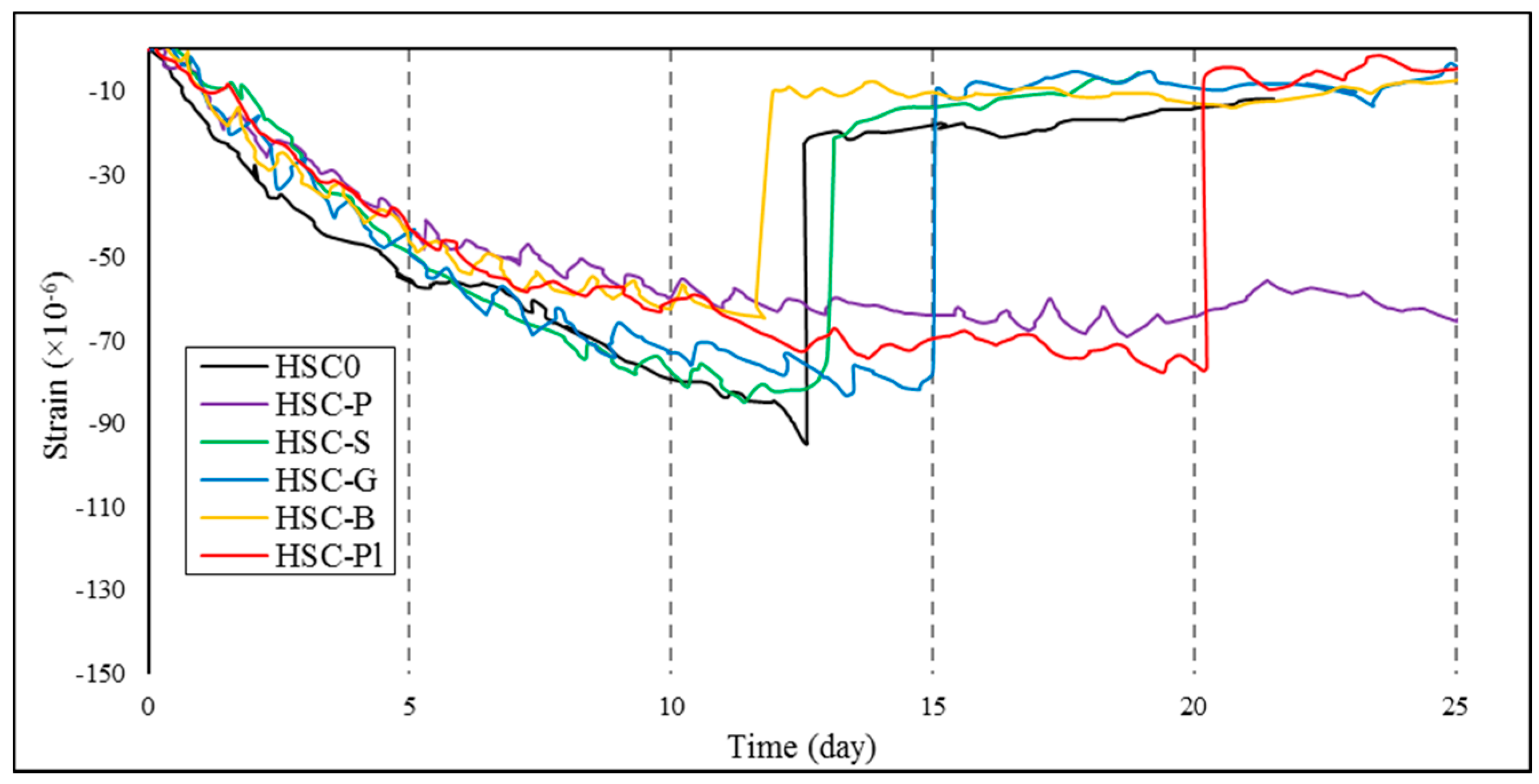
Concrete ring cracking via restrained shrinkage was evaluated, and the relative potential of fiber-reinforced concrete mixtures in shrinkage crack control at early ages was shown. The shrinkage test results are given in Table 5 and Figure 12. Three parameters were evaluated: (1) cracking age; (2) crack width; and (3) cracking type. Cracking age was evaluated using strain–time curves. Two types of cracks were observed: (1) full-depth cracks and (2) superficial cracks. According to Figure 12, cracks with full fracture are associated with an abrupt drop (more than 30 micro-strain) or a compatible drop in strain. Additionally, superficial cracks (the cracks which are not penetrated fully in specimen) are associated with strain–time curve as the local drop.
It can be seen that, after demolding, cracks generated on the concrete ring surface developed to full-depth cracks by 28 days; however, in polypropylene-fiber-containing mixtures (HSC-P), no signs of full-depth cracks were observed (Figure 12). This result shows that crack width was reinforced for this mixture.
Polypropylene- or steel-fiber-containing mixtures exhibited the largest and smallest crack widths, respectively. Polypropylene-fiber-containing mixtures obtained the best results in terms of width and time parameters. Cracking age increased from 13 to 21 days (a 62% increase: 13 days for the control and 21 days for the polypropylene-fiber-containing concrete), and crack width decreased up to 84% (0.4 mm for the control and 0.065 mm for the polypropylene-fiber-containing concrete).
Steel fibers showed a lower crack width (lower than half, compared to the control concrete) at first crack (at 11 days). It was seen that, in in vitro conditions, corrosion signs emerged in portions of steel-fiber-containing concrete ring surfaces. Additionally, cracking width increases compared to the control concrete as time passes. This could be due to the relatively high flexural strength of fibers used in the mixtures. Glass-, basalt-, and polyolefin-fiber-containing mixtures experienced higher cracking time, compared to the control; however, their crack widths were not considerably different from that of the control concrete. Figure 13 shows a close-up picture of a crack generated on a concrete ring surface of polypropylene-fiber-containing and non-fibrous specimens.
4. Conclusions
In this study, the effects of polypropylene, steel, glass, basalt, and polyolefin fibers on the compressive and flexural strength and shrinkage (early ages) of high-strength concrete were evaluated, and the following results were obtained:
- The presence of fibers at mixing time causes balling in fresh concrete and a relative drop of strength in hardened concrete at long-term periods. The addition of fibers caused an increase in the compressive strength at ages of 3, 7, and 28 days up to 16%, 20%, and 3%, respectively.
- Among concrete mixtures, only steel-fiber-containing specimens under bending exhibited post-crack behavior, such that toughness indexes of I5 and I110 were 4.1 and 7.7, respectively, with a residual stress of 0.75 MPa.
- The addition of fibers to concrete mixtures increased cracking age and decreased crack width. Comparison between shrinkage results showed that fibers with high stiffness (high flexural strength), such as steel or glass fibers, exhibited good performance in providing flexural strength, but they underperform relatively in terms of rate and time of restrained shrinkage cracking. Therefore, fibers such as steel, glass, and basalt are not recommended for restraining early age cracking, so that they cause an increased crack width and a decreased cracking age. Polyolefin and polypropylene fibers exhibit good performance in restraining shrinkage at early ages.
- Two types of cracks were observed in concrete rings: (1) full-depth cracks and (2) superficial cracks. Over 28 days, cracks generated on concrete ring surfaces developed into full-depth cracks; nevertheless, in polypropylene-fiber-containing mixtures, no signs of full-depth cracks were observed. Polypropylene-fiber-containing mixtures had the lowest crack width, causing an 84% decreased crack width as well as a 62% increased cracking age.
Author Contributions
This paper is part of Behzad Tahmouresi and Ashkan Saradar’s work research. They fabricated and tested the test specimens. All authors contributed to the analysis and interpretation of data and writing this paper.
Conflicts of Interest
The authors declare no conflict of interest.
References
- Aggarwal, Y.; Siddique, R. Microstructure and properties of concrete using bottom ash and waste foundry sand as partial replacement of fine aggregates. Constr. Build. Mater. 2014, 54, 210–223. [Google Scholar] [CrossRef]
- Sadrmomtazi, A.; Tahmouresi, B.; Kohani Khoshkbijari, R. Effect of fly ash and silica fume on transition zone, pore structure and permeability of concrete. Mag. Concr. Res. 2017, 1–14. [Google Scholar] [CrossRef]
- Mehrinejad Khotbehsara, M.; Mohseni, E.; Ozbakkaloglu, T.; Ranjbar, M.M. Durability Characteristics of Self-Compacting Concrete Incorporating Pumice and Metakaolin. J. Mater. Civ. Eng. 2017, 29, 04017218. [Google Scholar] [CrossRef]
- Johari, M.M.; Brooks, J.J.; Kabir, S.; Rivard, P. Influence of supplementary cementitious materials on engineering properties of high strength concrete. Constr. Build. Mater. 2011, 25, 2639–2648. [Google Scholar] [CrossRef]
- Naseri, F.; Jafari, F.; Mohseni, E.; Tang, W.; Feizbakhsh, A.; Khatibinia, M. Experimental observations and SVM-based prediction of properties of polypropylene fibres reinforced self-compacting composites incorporating nano-CuO. Constr. Build. Mater. 2017, 143, 589–598. [Google Scholar] [CrossRef]
- Mohseni, E.; Yazdi, M.A.; Miyandehi, B.M.; Zadshir, M.; Ranjbar, M.M. Combined Effects of Metakaolin, Rice Husk Ash, and Polypropylene Fiber on the Engineering Properties and Microstructure of Mortar. J. Mater. Civ. Eng. 2017, 29, 04017025. [Google Scholar] [CrossRef]
- Kwon, M.; Seo, H.; Kim, J. Seismic performance of RC-column wrapped with Velcro. Struct. Eng. Mech. 2016, 58, 379–395. [Google Scholar] [CrossRef]
- Mohseni, E.; Tang, W.; Cui, H. Chloride Diffusion and Acid Resistance of Concrete Containing Zeolite and Tuff as Partial Replacements of Cement and Sand. Materials 2017, 10, 372. [Google Scholar] [CrossRef] [PubMed]
- Triantafyllou, G.G.; Rousakis, T.C.; Karabinis, A.I. Corroded RC beams patch repaired and strengthened in flexure with fiber-reinforced polymer laminates. Compos. Part B-Eng. 2017, 112, 125–136. [Google Scholar] [CrossRef]
- Triantafyllou, G.G.; Rousakis, T.C.; Karabinis, A.I. Effect of patch repair and strengthening with EBR and NSM CFRP laminates for RC beams with low, medium and heavy corrosion. Compos. Part B-Eng. 2018, 133, 101–111. [Google Scholar] [CrossRef]
- Rousakis, T.C.; Tourtouras, I.S. Modeling of passive and active external confinement of RC columns with elastic material. ZAMM-J. Appl. Math. Mech./Z. Angew. Math. Mech. 2015, 95, 1046–1057. [Google Scholar] [CrossRef]
- Iqbal, S.; Ali, A.; Holschemacher, K.; Bier, T.A. Mechanical properties of steel fiber reinforced high strength lightweight self-compacting concrete (SHLSCC). Constr. Build. Mater. 2015, 98, 325–333. [Google Scholar] [CrossRef]
- Hannawi, K.; Bian, H.; Prince-Agbodjan, W.; Raghavan, B. Effect of different types of fibers on the microstructure and the mechanical behavior of Ultra-High Performance Fiber-Reinforced Concretes. Compos. Part B-Eng. 2016, 86, 214–220. [Google Scholar] [CrossRef] [Green Version]
- Zhang, P.; Li, Q.F. Effect of polypropylene fiber on durability of concrete composite containing fly ash and silica fume. Compos. Part B-Eng. 2013, 45, 1587–1594. [Google Scholar] [CrossRef]
- Ghanei, A.; Jafari, F.; Mehrinejad Khotbehsara, M.; Mohseni, E.; Tang, W.; Cui, H. Effect of Nano-CuO on Engineering and Microstructure Properties of Fibre-Reinforced Mortars Incorporating Metakaolin: Experimental and Numerical Studies. Materials 2017, 10, 1215. [Google Scholar] [CrossRef]
- Husem, M. The effects of high temperature on compressive and flexural strengths of ordinary and high-performance concrete. Fire Saf. J. 2006, 41, 155–163. [Google Scholar] [CrossRef]
- Mohseni, E.; Khotbehsara, M.M.; Naseri, F.; Monazami, M.; Sarker, P. Polypropylene fiber reinforced cement mortars containing rice husk ash and nano-alumina. Constr. Build. Mater. 2016, 111, 429–439. [Google Scholar] [CrossRef]
- Kodur, V.K.R.; Cheng, F.P.; Wang, T.C.; Sultan, M.A. Effect of strength and fiber reinforcement on fire resistance of high-strength concrete columns. J. Struct. Eng. 2003, 129, 253–259. [Google Scholar] [CrossRef]
- Sadrmomtazi, A.; Tahmouresi, B.; Saradar, A. Effects of silica fume on mechanical strength and microstructure of basalt fiber reinforced cementitious composites (BFRCC). Constr. Build. Mater. 2018, 162, 321–333. [Google Scholar] [CrossRef]
- Afroughsabet, V.; Biolzi, L.; Ozbakkaloglu, T. Influence of double hooked-end steel fibers and slag on mechanical and durability properties of high performance recycled aggregate concrete. Compos. Struct. 2017, 181, 273–284. [Google Scholar] [CrossRef]
- Martinelli, E.; Caggiano, A.; Xargay, H. An experimental study on the post-cracking behavior of Hybrid Industrial/Recycled Steel Fibre-Reinforced Concrete. Constr. Build. Mater. 2015, 94, 290–298. [Google Scholar] [CrossRef]
- Mohseni, E.; Saadati, R.; Kordbacheh, N.; Parpinchi, Z.S.; Tang, W. Engineering and microstructural assessment of fibre-reinforced self-compacting concrete containing recycled coarse aggregate. J. Clean. Prod. 2017, 168, 605–613. [Google Scholar] [CrossRef]
- Rousakis, T.C. Reusable and recyclable nonbonded composite tapes and ropes for concrete columns confinement. Compos. Part B-Eng. 2016, 103, 15–22. [Google Scholar] [CrossRef]
- Gesoğlu, M.; Özturan, T.; Güneyisi, E. Effects of cold-bonded fly ash aggregate properties on the shrinkage cracking of lightweight concretes. Cem. Concr. Compos. 2006, 28, 598–605. [Google Scholar] [CrossRef]
- Darwish, F.A.; Oliveira, T.M.; Coura, C.G.; Kitamura, S.; Barbosa, M.T.G.; Santos, W. Influence of Fiber Ratio in the Size Effect. In Proceedings of the International Conference Concrete: Construction’s Sustainable Option, Dundee, UK, 8–10 July 2008; pp. 123–130. [Google Scholar]
- Vandewalle, L. Hybrid Fiber Reinforced Concrete. In Measuring, Monitoring and Modeling Concrete Properties; Springer: Dordrecht, The Netherlands, 2006; pp. 77–82. [Google Scholar] [CrossRef]
- Beglarigale, A.; Yazıcı, H. Pull-out behavior of steel fiber embedded in flowable RPC and ordinary mortar. Constr. Build. Mater. 2015, 75, 255–265. [Google Scholar] [CrossRef]
- Toledo Filho, R.D.; Ghavami, K.; Sanjuán, M.A.; England, G.L. Free, restrained and drying shrinkage of cement mortar composites reinforced with vegetable fibres. Cem. Concr. Compos. 2005, 27, 537–546. [Google Scholar] [CrossRef]
- Kakooei, S.; Akil, H.M.; Jamshidi, M.; Rouhi, J. The effects of polypropylene fibers on the properties of reinforced concrete structures. Constr. Build. Mater. 2012, 27, 73–77. [Google Scholar] [CrossRef]
- Saje, D.; Bandelj, B.; Šušteršič, J.; Lopatič, J.; Saje, F. Shrinkage of polypropylene fiber-reinforced high-performance concrete. J. Mater. Civ. Eng. 2010, 23, 941–952. [Google Scholar] [CrossRef]
- Yousefieh, N.; Joshaghani, A.; Hajibandeh, E.; Shekarchi, M. Influence of fibers on drying shrinkage in restrained concrete. Constr. Build. Mater. 2017, 148, 833–845. [Google Scholar] [CrossRef]
- Mostofinejad, D.; Hatem, N. The effect of polypropylene fibers on cracking caused polyolefin shrinkage and concrete performance. J. Civil. Eng. 2004, 16, 73–86. [Google Scholar]
- Tassew, S.T.; Lubell, A.S. Mechanical properties of glass fiber reinforced ceramic concrete. Constr. Build. Mater. 2014, 51, 215–224. [Google Scholar] [CrossRef]
- Saghi, H.; Delbari, H. The effect of the polyolefin fibers and concrete strength on polyolefin shrinkage cracking in concrete slabs. J. Concr. Res. 2015, 8, 35–46. [Google Scholar]
- Lee, M.S.; Seo, T.S. Prediction method of drying shrinkage crack in reinforced concrete walls. Int. J. Civ. Eng. 2014, 12, 73–81. Available online: http://ijce.iust.ac.ir/article-1-657-en.html (accessed on 1 November 2017).
- Löfgren, I. Fibre-Reinforced Concrete for Industrial Construction—A Fracture Mechanics Approach to Material Testing and Structural Analysis; Chalmers University of Technology: Göteborg, Sweden, 2005; ISBN 91-7291-696-6. [Google Scholar]
- ASTM C150. Standard Specification for Portland Cement; ASTM International: West Conshohocken, PA, USA, 2012. [Google Scholar]
- ASTM C1240. Standard Specification for Silica Fume Used in Cementitious Mixtures; ASTM International: West Conshohocken, PA, USA, 2012. [Google Scholar]
- ASTM C995. Standard Test Method for Time of Flow of Fiber-Reinforced Concrete through Inverted Slump Cone (Withdrawn 2008); ASTM International: West Conshohocken, PA, USA, 2012. [Google Scholar]
- BS EN 12390-3:2009. Testing Hardened Concrete. Compressive Strength of Test Specimens; British Standard Institution: London, UK, 2009. [Google Scholar]
- ASTM C1609. Standard Test Method for Flexural Performance of Fiber-Reinforced Concrete (Using Beam with Third-Point Loading); ASTM International: West Conshohocken, PA, USA, 2012. [Google Scholar]
- Mao, L.; Barnett, S.J. Investigation of toughness of ultra-high performance fibre reinforced concrete (UHPFRC) beam under impact loading. Int. J. Impact Eng. 2017, 99, 26–38. [Google Scholar] [CrossRef]
- ASTM C1581. Standard Test Method for Determining Age at Cracking and Induced Tensile Stress Characteristics of Mortar and Concrete under Restrained Shrinkage; ASTM International: West Conshohocken, PA, USA, 2016. [Google Scholar]
Figure 1.
Schematic description of the effect of fiber on the fracture process of concrete in tensile loading [36]. Reproduced with permission from Löfgren, 2005.
Figure 1.
Schematic description of the effect of fiber on the fracture process of concrete in tensile loading [36]. Reproduced with permission from Löfgren, 2005.
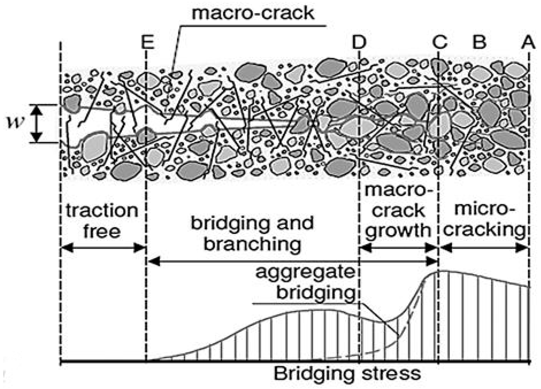
Figure 2.
Particle size distribution of the fine and coarse aggregate.
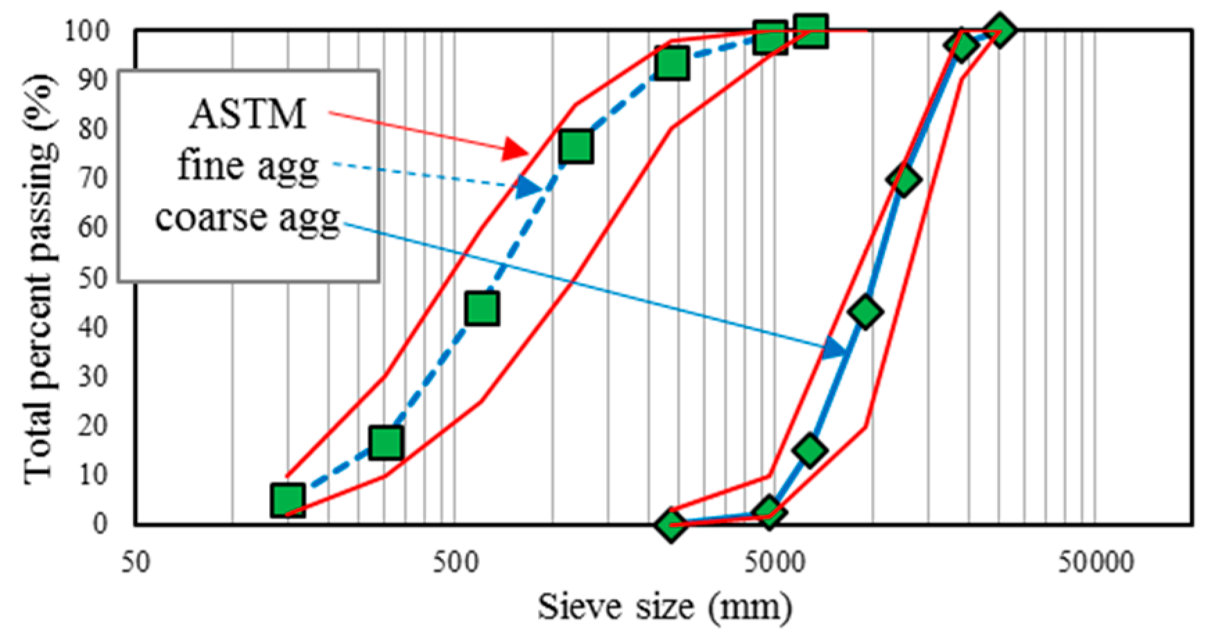
Figure 3.
Concrete mixtures under curing: (a) coated with a polyolefin cover before demolding; (b) wet condition after demolding.
Figure 3.
Concrete mixtures under curing: (a) coated with a polyolefin cover before demolding; (b) wet condition after demolding.
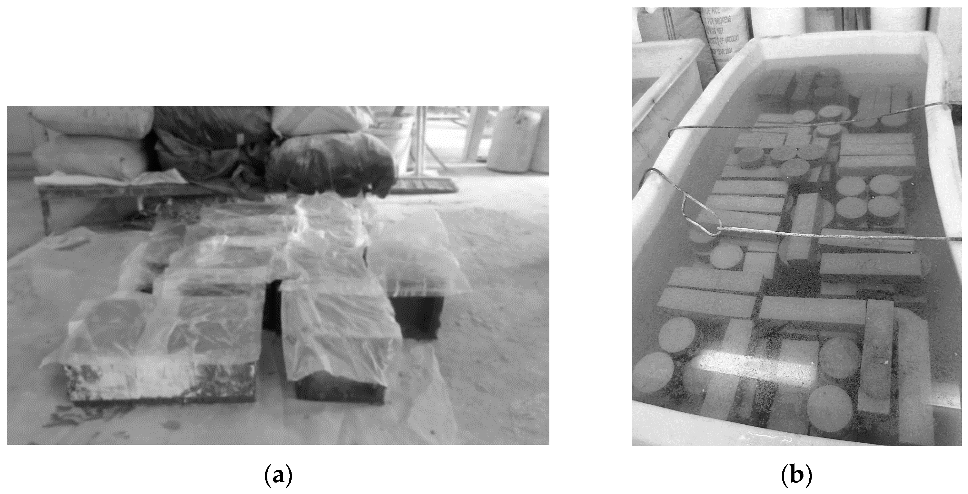
Figure 4.
Flexural strength machine: (a) prismatic specimen under four- point flexural; (b) configuration of four- point flexural test.
Figure 4.
Flexural strength machine: (a) prismatic specimen under four- point flexural; (b) configuration of four- point flexural test.
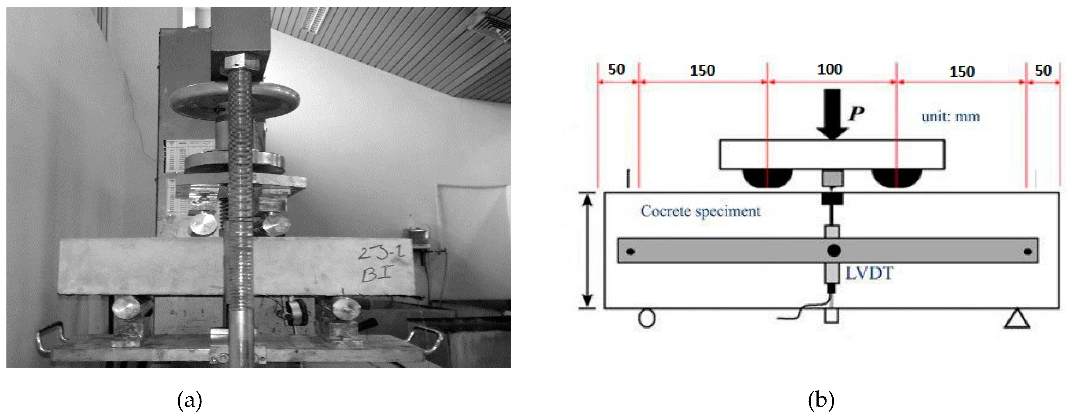
Figure 5.
Details of the ring mold listed in the standard.

Figure 6.
Measurement process of concrete rings.
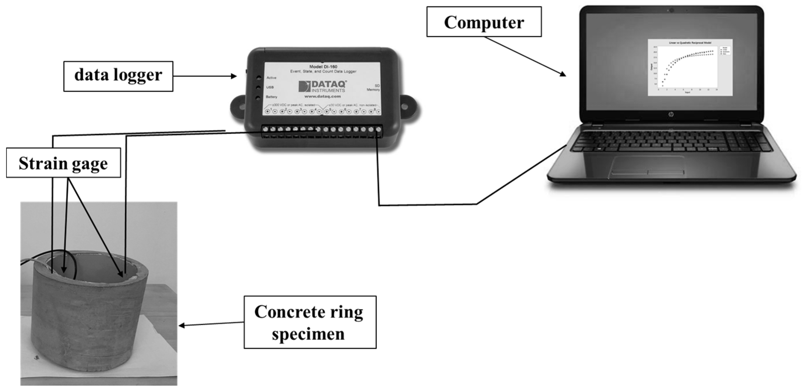
Figure 7.
The flow time of fresh concrete mixtures.

Figure 8.
Compressive strength of concrete mixtures.
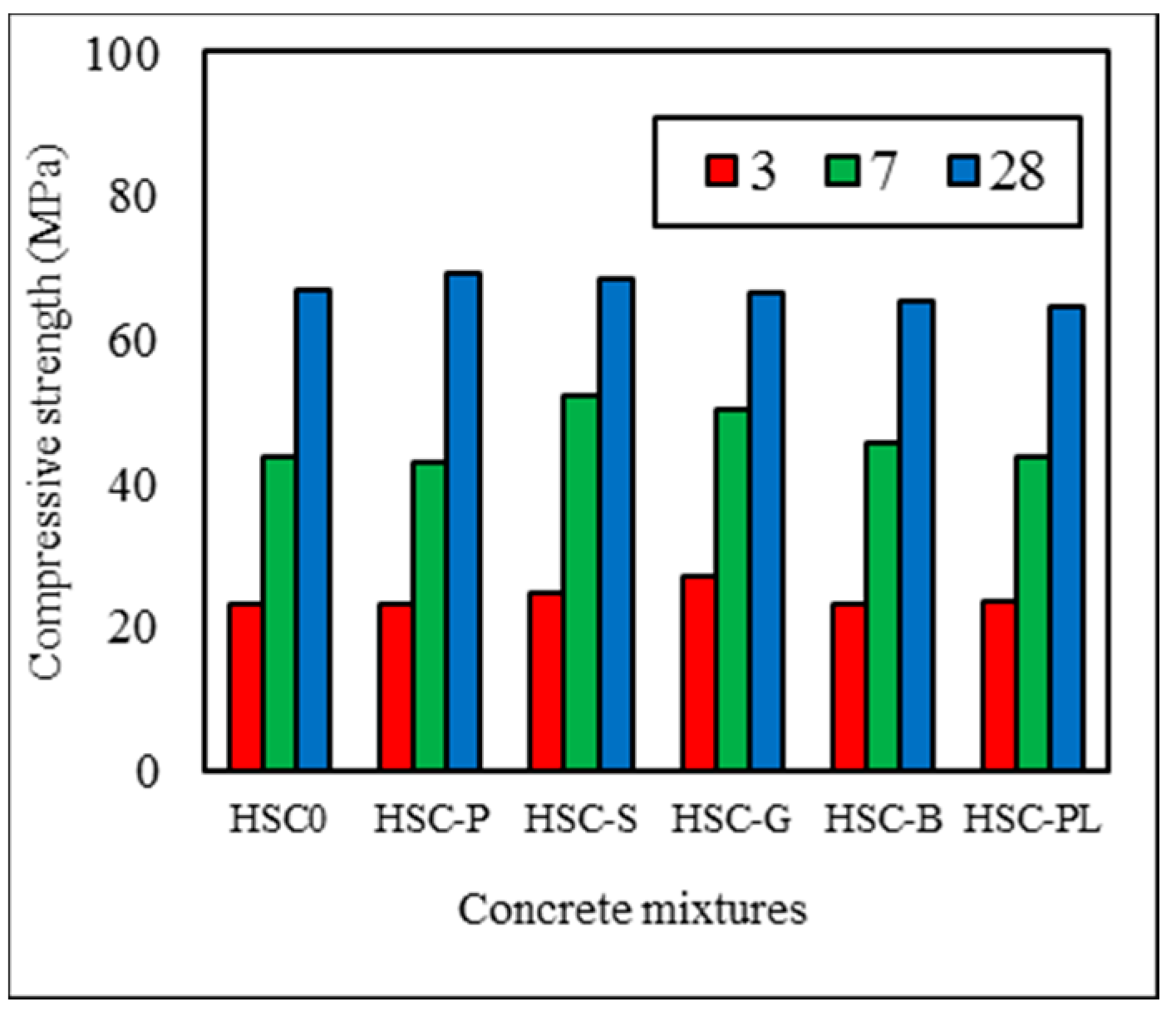
Figure 9.
Load–deflection of specimens prismatic.
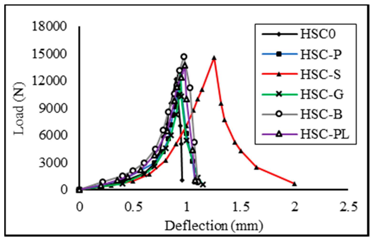
Figure 10.
Pull-out of steel fibers and fiber bridging.
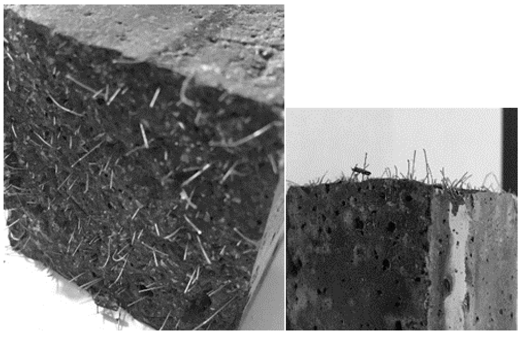
Figure 11.
Prismatic samples under flexural loading: (a) specimen without fiber; (b) specimen containing steel fibers.
Figure 11.
Prismatic samples under flexural loading: (a) specimen without fiber; (b) specimen containing steel fibers.

Figure 12.
Strain–time curves of concrete mixtures.

Figure 13.
The shrinkage crack width of concrete ring: (a) specimen without fiber; (b) specimen containing polypropylene (PP) fiber.
Figure 13.
The shrinkage crack width of concrete ring: (a) specimen without fiber; (b) specimen containing polypropylene (PP) fiber.


Table 1.
Chemical composition of cementitious materials (% by mass).
| Materials | Chemical Composition (% by Mass) | |||||||
|---|---|---|---|---|---|---|---|---|
| CaO | SiO2 | Al2O3 | Fe2O3 | MgO | K2O | Na2O | SO3 | |
| Cement | 64.37 | 21.08 | 5.36 | 3.64 | 2 | 0.82 | 0.5 | 2.2 |
| Silica fume | 1.5 | 92 | 1.5 | 2.5 | 2 | - | - | - |
Table 2.
Characteristics of fibers.
| Fiber Type | Shape | Length (mm) | Diameter (mm) | Density (g/cm3) | Tensile Strength (MPa) | Elasticity Modulus (GPa) |
|---|---|---|---|---|---|---|
| Steel |  | 13 | 0.2 | 7.85 | 1000 | 210 |
| Polypropylene |  | 12 | 0.02 | 0.91 | 451 | 4.5 |
| Glass |  | 12 | 0.012 | 2.7 | 1850 | 65 |
| Basalt |  | 12 | 0.01 | 2.67 | 2100 | 79 |
| Polyolefin |  | 12 | 1.07 | 0.92 | 350 | 6 |
Table 3.
Proportions of the investigated concrete mixtures.
| MIX ID | W/Bi # | Cement | Silica fume | Aggregate | Fibers | ||||||
|---|---|---|---|---|---|---|---|---|---|---|---|
| Fine | Coarse | SP | PP | ST | G | B | P | ||||
| HSC-0 * | 0.38 | 405 | 45 | 781 | 1016 | 2.32 | - | - | - | - | - |
| HSC-P | 0.38 | 405 | 45 | 781 | 1016 | 3 | 0.91 | - | - | - | - |
| HSC-S | 0.38 | 405 | 45 | 781 | 1016 | 2.9 | - | 7.85 | - | - | - |
| HSC-G | 0.38 | 405 | 45 | 781 | 1016 | 2.55 | - | - | 2.7 | - | - |
| HSC-B | 0.38 | 405 | 45 | 781 | 1016 | 2.75 | - | - | - | 2.67 | - |
| HSC-PL | 0.38 | 405 | 45 | 781 | 1016 | 2.65 | - | - | - | - | 1.3 |
*: 0: no fibers, #: Bi: binder, SP: superpolyolefinizer, PP: polypropylene, ST: steel, G: glass, B: basalt, P: polyolefin.
Table 4.
Summary of flexural strength testing.
| MIX ID | Ultimate Load (KN) | Ultimate Flexural Strength (MPa) | Ultimate Load Deflection (mm) | First Crack Absorbed Energy (KN-mm) | First Crack Toughness (N/mm × 10−4) |
|---|---|---|---|---|---|
| HSC0 | 12.1 | 4.8 | 0.9 | 2.42 | 2419.5 |
| HSC-P | 12.5 | 5 | 0.93 | 2.86 | 2860 |
| HSC-S | 14.6 | 5.84 | 1.25 | 5.3 | 5281.7 |
| HSC-G | 13 | 5.2 | 0.94 | 2 | 1988.1 |
| HSC-B | 14.7 | 5.88 | 0.97 | 4.2 | 4284.6 |
| HSC-PL | 13.7 | 5.48 | 0.98 | 2.4 | 2406.9 |
Table 5.
The results of cracking age and crack width of concrete rings.
| MIX ID | Crack Width (mm × 10−2) | Average Crack Age (day) | Full Depth Crack |
|---|---|---|---|
| HSC0 | 41 | 13 | Y |
| HSC-P | 6.5 | 21 | NONE |
| HSC-S | 20 | 11 | Y |
| HSC-G | 45 | 15 | Y |
| HSC-B | 45 | 14 | Y |
| HSC-PL | 40 | 20 | Y |
© 2018 by the authors. Licensee MDPI, Basel, Switzerland. This article is an open access article distributed under the terms and conditions of the Creative Commons Attribution (CC BY) license (http://creativecommons.org/licenses/by/4.0/).
Share and Cite
MDPI and ACS Style
Saradar, A.; Tahmouresi, B.; Mohseni, E.; Shadmani, A. Restrained Shrinkage Cracking of Fiber-Reinforced High-Strength Concrete. Fibers 2018, 6, 12. https://doi.org/10.3390/fib6010012
AMA Style
Saradar A, Tahmouresi B, Mohseni E, Shadmani A. Restrained Shrinkage Cracking of Fiber-Reinforced High-Strength Concrete. Fibers. 2018; 6(1):12. https://doi.org/10.3390/fib6010012
Chicago/Turabian StyleSaradar, Ashkan, Behzad Tahmouresi, Ehsan Mohseni, and Ali Shadmani. 2018. "Restrained Shrinkage Cracking of Fiber-Reinforced High-Strength Concrete" Fibers 6, no. 1: 12. https://doi.org/10.3390/fib6010012
Note that from the first issue of 2016, this journal uses article numbers instead of page numbers. See further details here.