The Fiber Connection Method Using a Tapered Silica Fiber Tip for Microstructured Polymer Optical Fibers

 , and
, and 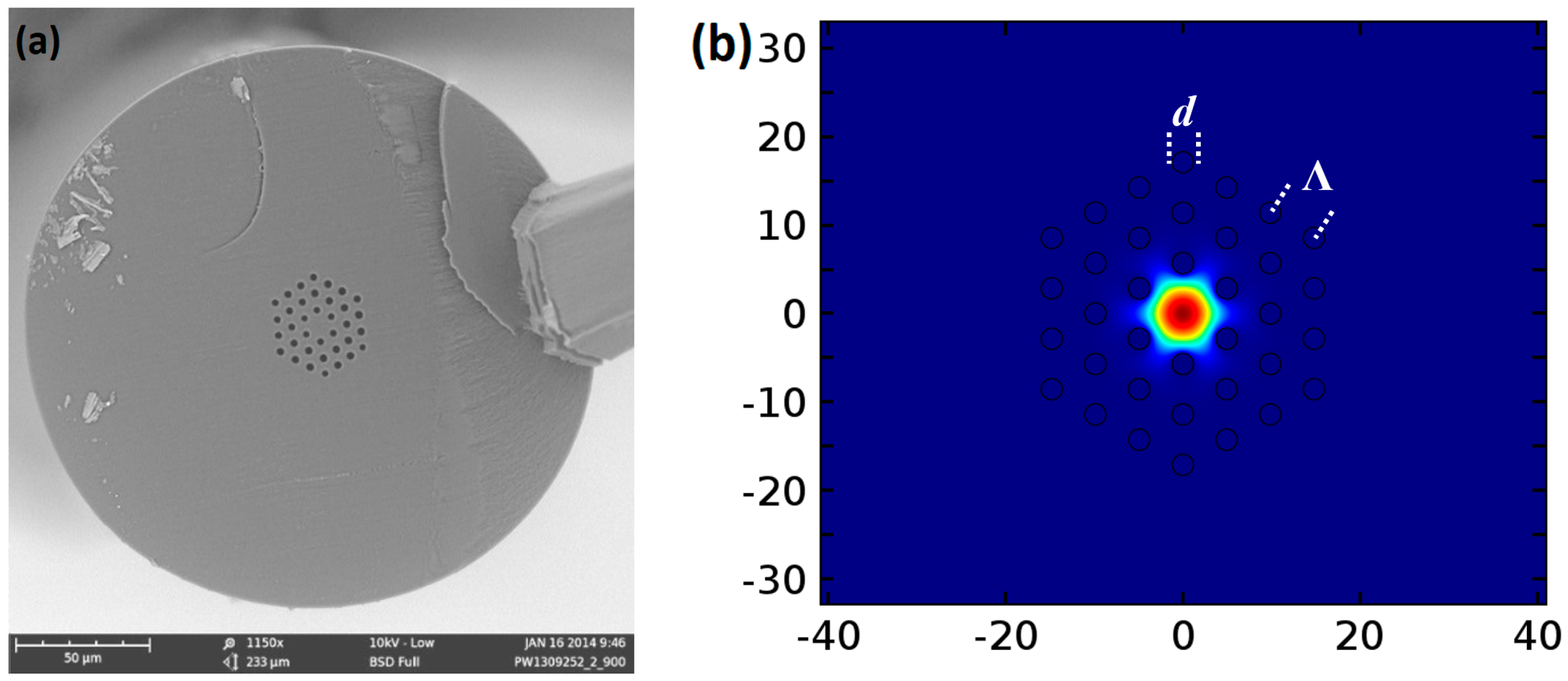
Abstract
:1. Introduction
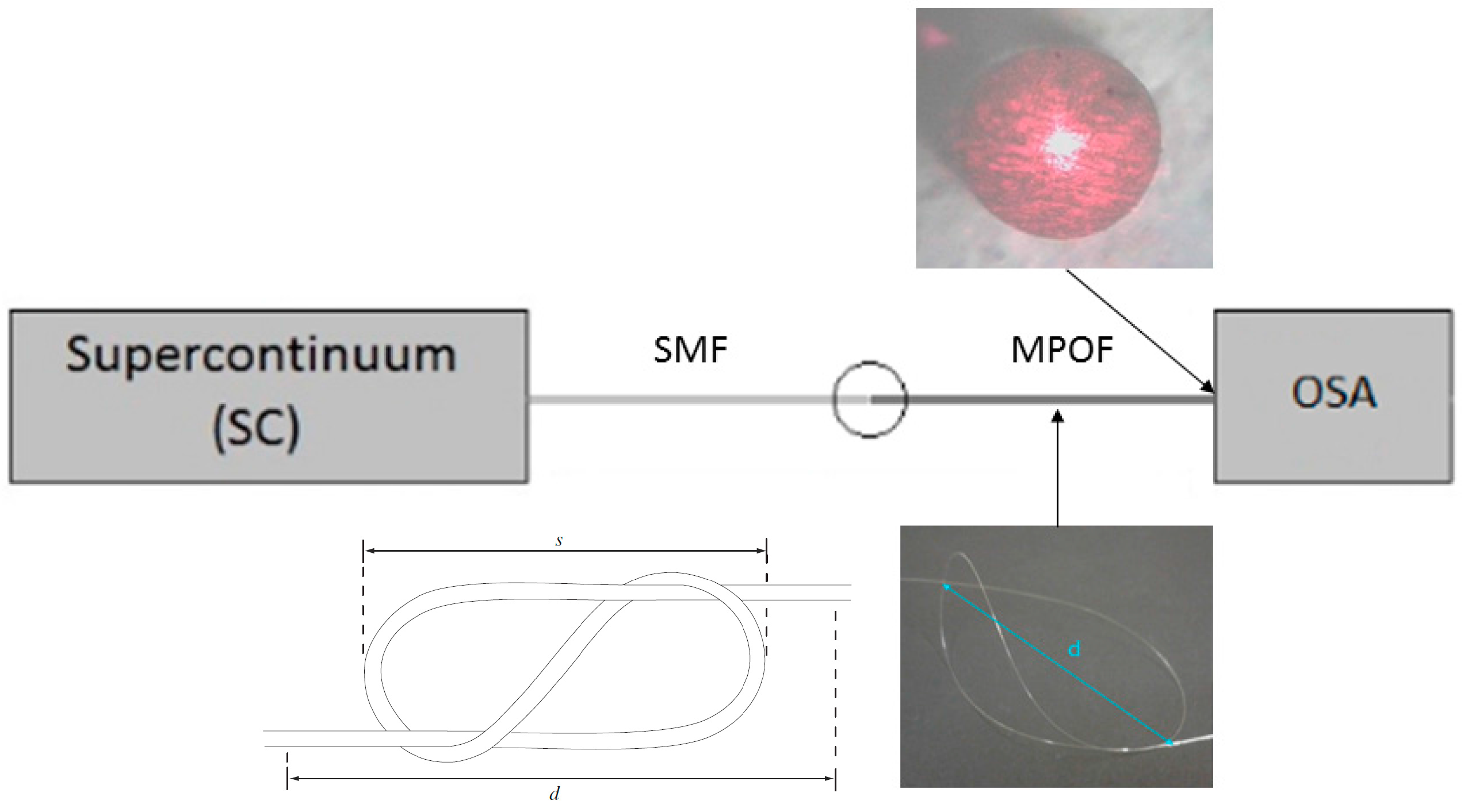
2. Materials and Methods
3. Results
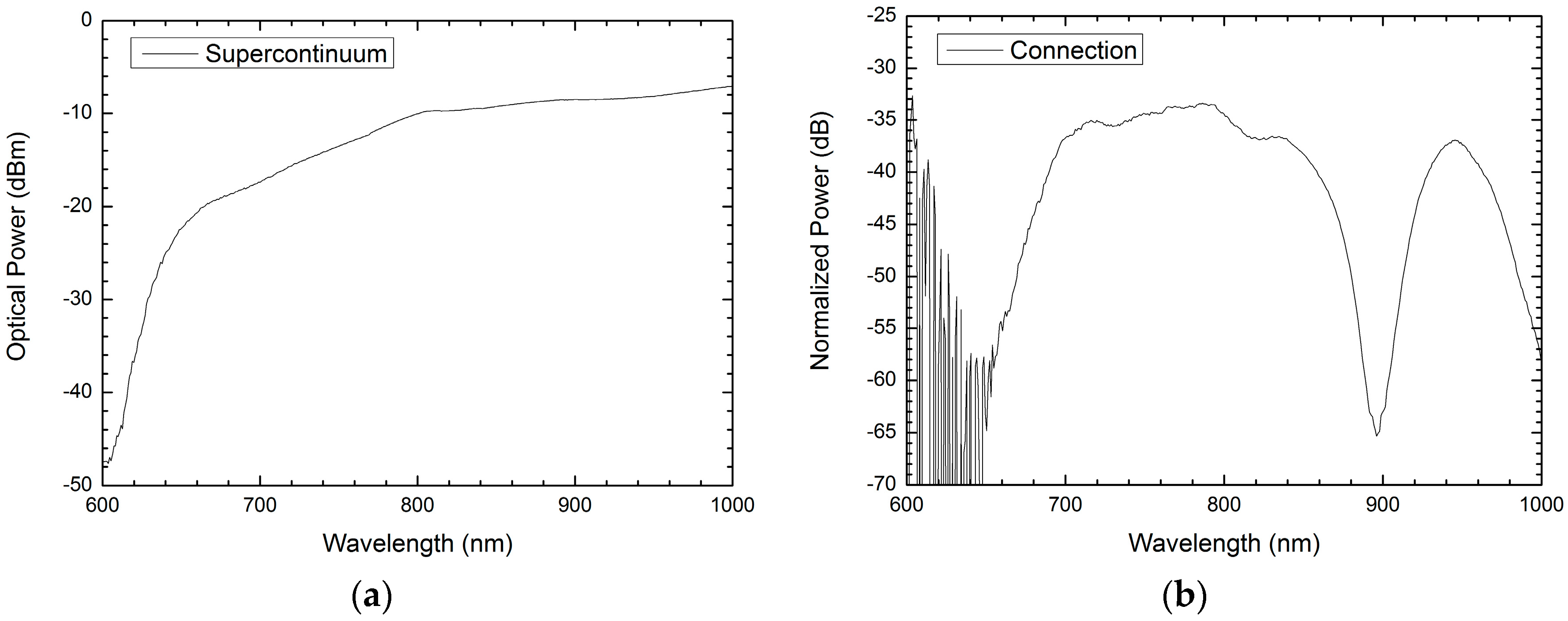
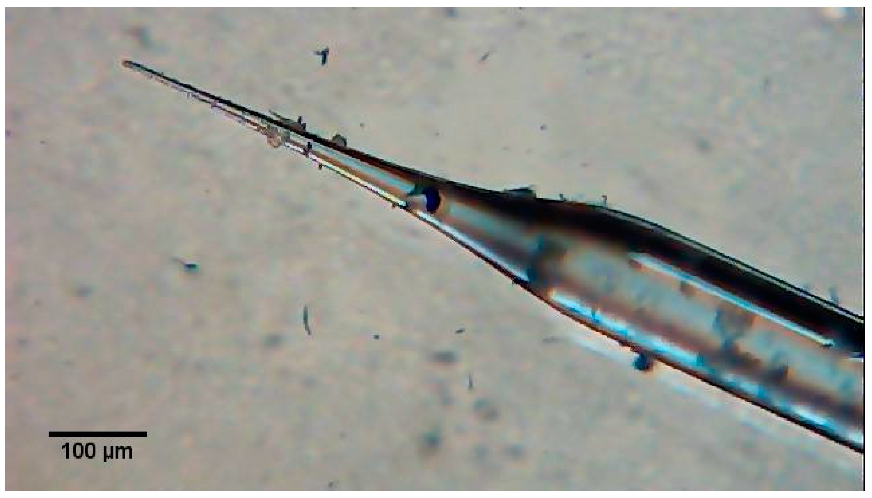
3.1. Connection
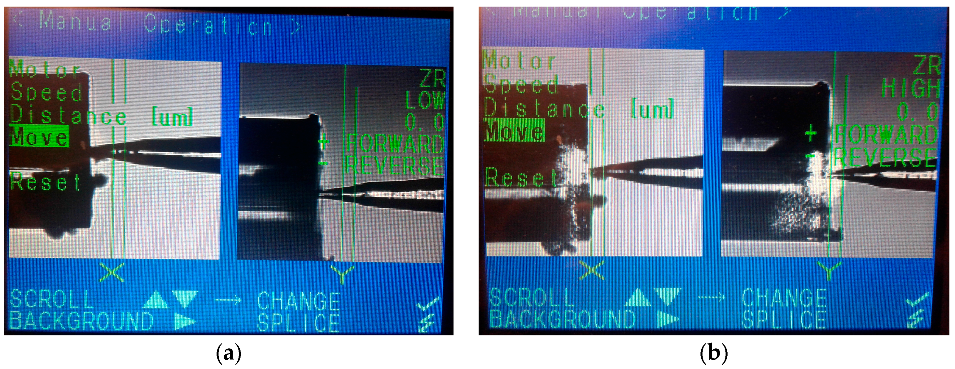
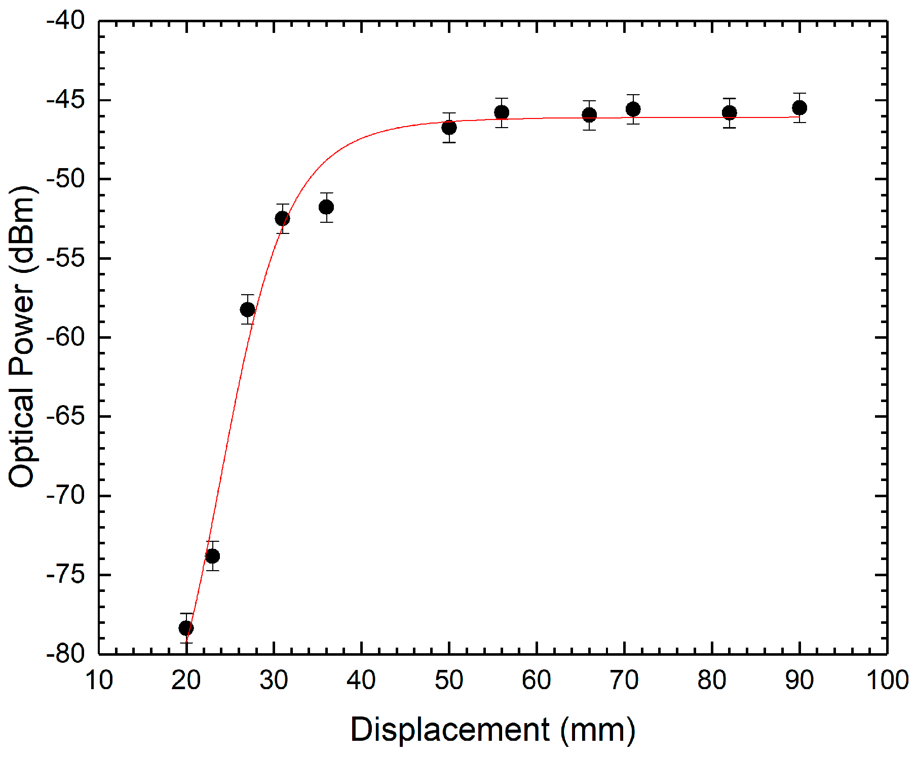
3.2. Displacement Test
4. Discussion
Acknowledgments
Author Contributions
Conflicts of Interest
References
- Koike, Y.; Ishigure, T.; Nihei, E. High-bandwidth graded-index polymer optical fibre. Polymer 1991, 32, 1737–1745. [Google Scholar] [CrossRef]
- Ishigure, T.; Nihei, E.; Koike, Y. Graded-index polymer optical fiber for high-speed data communication. Appl. Opt. 1994, 33, 4261–4266. [Google Scholar] [CrossRef] [PubMed]
- Chen, X.F.; Zhang, C.; Webb, D.J.; Peng, G.-D.; Kalli, K. Bragg grating in polymer optical fibre for strain, bend and temperature sensing. Meas. Sci. Technol. 2010, 21, 94005. [Google Scholar] [CrossRef]
- Johnson, I.P.; Webb, D.J.; Kalli, K. Hydrostatic pressure sensing using a polymer optical fibre Bragg gratings. In Proceedings of the Asia Pacific Optical Sensors Conference, Chengdu, China, 31 January–3 February 2012; Volume 8351, pp. 835106–835107. [Google Scholar]
- Ferreira, M.F.S.; Statkiewicz-Barabach, G.; Kowal, D.; Mergo, P.; Urbanczyk, W.; Frazão, O. Fabry-Perot cavity based on polymer FBG as refractive index sensor. Opt. Commun. 2017, 394, 37–40. [Google Scholar] [CrossRef]
- Jensen, J.; Hoiby, P.; Emiliyanov, G.; Bang, O.; Pedersen, L.; Bjarklev, A. Selective detection of antibodies in microstructured polymer optical fibers. Opt. Express 2005, 13, 5883–5889. [Google Scholar] [CrossRef] [PubMed]
- Yang, D.X.; Yu, J.; Tao, X.; Tam, H. Structural and mechanical properties of polymeric optical fiber. Mater. Sci. Eng. A 2004, 364, 256–259. [Google Scholar] [CrossRef]
- Abang, A.; Webb, D.J. Demountable connection for polymer optical fiber grating sensors. Opt. Eng. 2012, 51, 80503. [Google Scholar] [CrossRef]
- Abang, A.; Saez-Rodriguez, D.; Nielsen, K.; Bang, O.; Webb, D.J. Connectorisation of fibre Bragg grating sensors recorded in microstructured polymer optical fibre. In Proceedings of the Fifth European Workshop on Optical Fibre Sensors, Krakow, Poland, 19–22 May 2013; Volume 8794, p. 87943Q. [Google Scholar]
- Chen, X.; Zhang, C.; Webb, D.J.; Kalli, K.; Peng, G.D. Highly sensitive bend sensor based on bragg grating in eccentric core polymer fiber. IEEE Photonics Technol. Lett. 2010, 22, 850–852. [Google Scholar] [CrossRef]
- Durana, G.; Gómez, J.; Aldabaldetreku, G.; Zubia, J.; Montero, A.; De Ocáriz, I.S. Assessment of an LPG mPOF for strain sensing. IEEE Sens. J. 2012, 12, 2668–2673. [Google Scholar] [CrossRef]
- Birks, T.A.; Knight, J.C.; Russell, P.S. Endlessly single-mode photonic crystal fiber. Opt. Lett. 1997, 22, 961–963. [Google Scholar] [CrossRef] [PubMed]
- Large, M.C.J.; Van Eijkelenborg, M.A.; Argyros, A.; Zagari, J.; Manos, S.; Issa, N.A.; Bassett, I.; Fleming, S.; Mcphedran, R.C.; De, C.M.; et al. Microstructured polymer optical fibers: Progress and promise. In Proceedings of the International Symposium on Biomedical Optics, San Jose, CA, USA, 19–25 January 2002; Volume 4616, pp. 105–116. [Google Scholar]
- Barton, G.; Van Eijkelenborg, M.A.; Henry, G.; Large, M.C.J.; Zagari, J. Fabrication of microstructured polymer optical fibres. Opt. Fiber Technol. 2004, 10, 325–335. [Google Scholar] [CrossRef]
- Gomes, A.D.; Frazão, O. Mach-Zehnder Based on Large Knot Fiber Resonator for Refractive Index Measurement. IEEE Photonics Technol. Lett. 2016, 28, 1279–1281. [Google Scholar] [CrossRef]
- Tao, M.; Jin, Y.; Gu, N.; Huang, L. A method to control the fabrication of etched optical fiber probes with nanometric tips. J. Opt. 2009, 12, 15503. [Google Scholar] [CrossRef]
- Nikbakht, H.; Latifi, H.; Amini, T.; Chenari, Z. Controlling cone angle of the tapered tip fiber using dynamic etching. In Proceedings of the 23rd International Conference on Optical Fiber Sensors, Santander, Spain, 2–6 June 2014; Volume 9157, p. 91574Q. [Google Scholar] [CrossRef]
- Haber, L.H.; Schaller, R.D.; Johnson, J.C.; Saykally, R.J. Shape control of near-field probes using dynamic meniscus etching. J. Microsc. 2004, 214, 27–35. [Google Scholar] [CrossRef] [PubMed]
- Barucci, A.; Cosi, F.; Giannetti, A.; Pelli, S.; Griffini, D.; Insinna, M.; Salvadori, S.; Tiribilli, B.; Righini, G.C. Optical fibre nanotips fabricated by a dynamic chemical etching for sensing applications. J. Appl. Phys. 2015, 117. [Google Scholar] [CrossRef]
- Hornak, L.A. Polymers for Lightwave and Integrated Optics: Technology and Applications; CRC Press: New York, NY, USA, 1992. [Google Scholar]
- Oliveira, R. Novel Techniques and Devices for Optical Communications and Sensing Technologies; University of Aveiro: Aveiro, Portugal, 2017. [Google Scholar]


© 2018 by the authors. Licensee MDPI, Basel, Switzerland. This article is an open access article distributed under the terms and conditions of the Creative Commons Attribution (CC BY) license (http://creativecommons.org/licenses/by/4.0/).
Share and Cite
Ferreira, M.; Gomes, A.; Kowal, D.; Statkiewicz-Barabach, G.; Mergo, P.; Frazão, O. The Fiber Connection Method Using a Tapered Silica Fiber Tip for Microstructured Polymer Optical Fibers. Fibers 2018, 6, 4. https://doi.org/10.3390/fib6010004
Ferreira M, Gomes A, Kowal D, Statkiewicz-Barabach G, Mergo P, Frazão O. The Fiber Connection Method Using a Tapered Silica Fiber Tip for Microstructured Polymer Optical Fibers. Fibers. 2018; 6(1):4. https://doi.org/10.3390/fib6010004
Chicago/Turabian StyleFerreira, Miguel, André Gomes, Dominik Kowal, Gabriela Statkiewicz-Barabach, Pawel Mergo, and Orlando Frazão. 2018. "The Fiber Connection Method Using a Tapered Silica Fiber Tip for Microstructured Polymer Optical Fibers" Fibers 6, no. 1: 4. https://doi.org/10.3390/fib6010004