Effect of Adding Carbon Nanotubes on the Freeze-Thaw and Thermal Fatigue Resistance of Latex Modified Mortar


1
College of Engineering, McNeese State University, 4205 Ryan St., Lake Charles, LA 70605, USA
2
College of Engineering, Assiut University, Assiut 71516, Egypt
3
College of Engineering, Ohio Northern University, 525 S Main St., Ada, OH 45810, USA
*
Author to whom correspondence should be addressed.
Fibers 2018, 6(2), 19; https://doi.org/10.3390/fib6020019
Submission received: 13 January 2018
/
Revised: 2 March 2018
/
Accepted: 5 March 2018
/
Published: 2 April 2018
Abstract
:This paper aims to investigate the effect of adding carbon nanotubes (CNTs) on the durability of latex modified mortar (LMM). Up to 2.5% of CNTs by wt. of styrene-butadiene latex (SBR latex) CNTs were added to latex modified mortar (LMM) specimens before they are subjected to two different thermal tests: freeze-thaw and thermal fatigue. LMM specimens were subjected to a number of freeze-thaw cycles according to American Society for Testing and Materials (ASTM) C-666 in order to simulate winter outdoor conditions in the United States (US) northern areas. Also, the specimens were subjected to thermal fatigue cycles similar to summer outdoor conditions. A large number of specimens were prepared in cubes, cylinders, and prisms, and were mechanically tested in compression, splitting tension, and flexure in order to evaluate the LMM specimens after the thermal exposure. Compression and tension specimens were tested after 50% and after 100% of the total number of cycles in order to assess the effect of the number of cycles on the mechanical performance. For LMM prims, dimensional stability was assessed first by monitoring the development of shrinkage strains during the application of thermal cycles. The LMM prisms were then tested in flexure after the completion of all the thermal cycles. The effectiveness of adding CNTs was evaluated by comparing between the performance of control LMM specimens and those with different CNTs contents. CNTs were found to alter the compressive strength, tensile strength, and flexural load carrying capacity of LMM specimens.
1. Introduction
Latex modified concretes (LMC), also known as polymer modified concretes (PMC), have been introduced to the construction industry in the last century due to its relatively higher bond characteristics and better durability when compared to ordinary Portland cement concrete. LMC mixtures are typically constructed by replacing portion of the hydraulic cement paste by polymer additives. The polymer additives will form membranes or films within the LMC mixtures, leading to improved chemical resistance and reduced permeability and shrinkage [1]. Some of the current structural applications of LMCs include bridge deck overlays, flooring systems against aggressive environments, water tanks and swimming pools [1,2]. Such structural applications require careful design and selection of appropriate concrete mixtures in order to increase their life-span and reduce their life cycle cost. The life-span of concrete structures constructed in aggressive environments is shown to depend significantly on the durability of the used concrete mixture. Sun et al. [3] have drawn the following important traits for concrete subjected to freeze-thaw cycles and service loading: (1) A higher stress/strength ratio yields a higher damage rate and extent of the damage; (2) The higher the grade of concrete, the less damage that the concrete endures. Most damage in modern engineering materials stems from two or more actions taking place within the material. For concrete, the two actions acting on the concrete are typically loading and rapid freezing and thawing. Such combination deteriorates the concrete and requires continuous repair in order to maintain the concrete material in a satisfactory condition.
Several studies have examined the durability of concrete subjected to freeze and thaw cycles. Mu et al. [4] investigated the interaction between loading, freeze-thaw cycles, and chloride salt attack of concrete with and without steel fiber reinforcement. Concrete deterioration was further accelerated when freeze-thaw cycles, loading, and chloride salt attacks all acted simultaneously. The usual sensation that causes concrete to deteriorate in freeze-thaw tests is due to the weight loss that is caused by the scaling of the concrete’s surface. Concrete exposed to a NaCl solution instead of water experienced more weight loss during freeze-thaw tests than that in water. When the stress/strength ratio for the concrete was high, brittle failure occurred at early stages in the testing. Cai et al. [5] determined that freezing of water inside pores causes hydraulic internal pressure, which in turn, damages the concrete. They also discovered that freezing points of concrete differed with pore size (smaller pore size yielded lower freezing points). Jacobsen et al. [6,7] investigated a self-healing mechanism on concrete underwent frost deterioration. Freeze-thaw test is used to simulate the effects of frost on the concrete. It is observed that concrete regained much of its lost stiffness, represented by resonance frequency, after the self-healing process, while concrete regained only a small portion of its compressive strength. Jacobsen et al. also found that the amount of water that was uptaken during testing was directly related to the damage. The team found that the volume of the cracking is correlated to the volume increase of the concrete samples, and the cracks formed from testing had very high densities.
A number of investigations have addressed the effect of adding nanomaterials, such as carbon nanotubes (CNTs), on the performance of the mortar or concrete mixture. In nanotechnology, carbon nanotubes (CNTs) and other nanomaterials have been introduced as additives to different materials to improve the mechanical, thermal, and electrical characteristics [8]. In the construction industry, several nanomaterials have been introduced to concrete and cementitious materials along with CNTs in the last two decades, such as nano SiO2, TiO2, ZnO2, Fe2O3, Al2O3, and CuO [9,10]. The addition of nanomaterials aimed to control and manipulate the chemical structure of cement at the nanoscale. However, the effective use of nanomaterias in cementitious materials depends upon the ability to obtain fair dispersion of the nanomaterials in the dispersion media. Therefore, some experimental studies are directed to find the most suitable methods to obtain uniform dispersion of the nanomaterials in the mixtures. Tyson et al. [11] found that ultrasonic mixing seems to be the best way to effectively spread CNTs and carbon nanofibers (CNFs) in the mix. In almost all of the cases, it was found that adding CNTs and CNFs aides in improving the properties of the cement pastes. Sobolkina et al. [12] focused on understanding the relationship between CNTs dispersion and the mechanical properties of their respective cement mixes. In general, the study concluded that a proper distribution of CNTs in the cementitous mixture is essential for improving the mechanical properties. For the hardened cement paste, it was found that the compressive strength was greatly improved under high strain rate loading. No visible improvement was observed for the concrete under quasi-static loading.
A limited number of studies investigated the freeze and thaw resistance of mixtures containing nanoparticles. Salemi et al. [10] studied the freeze and thaw resistance of concrete mixes using different types of nanoparticles, including ZnO2, TiO2, Fe2O3, and Al2O3. Mixes with nanoparticles had higher compressive strength and lower water absorption. In addition, mixes with nanoparticles retained more strength and less cracking after being exposed to freezing and thawing tests. Wang et al. [13] investigated freeze and thaw resistance of concrete with CNTs. CNT-based concretes proved to outperform ordinary concrete when subjected to freeze-thaw cycles. Li et al. [14] found that CNT-based concretes perform better than ordinary concrete in both freeze-thaw and drying tests. It is theorized that this is because of a bridging effect of the carbon nanotubes and also the decrease in the number of large pores that are associated with the addition of CNTs. Cwirzen et al. [15] investigated the effect of carbon nano- and microfibers (CMFs) on strength and residual cumulative strain of mortars that were subjected to freeze-thaw cycles. Utilization of CMFs proved to be much more useful than the use of CNTs. The addition of CNTs to a cement mix was not able to prevent cracks from forming during freeze-thaw cycles. CNTs were able to make cracking happen at a less “explosive” degree.
In this study, we examine the use of CNTs to improve the durability of latex modified mortar as an example for polymer modified cementitious (PMC) materials. Previous studies have shown promising results in the short term response of PMCs reinforced with CNTs [16,17,18]. However, few or no studies addressed the effect of CNTs on the long term performance of PMCs. Different contents of CNTs were added to LMM mixtures and the durability of LMM mixes was evaluated through freeze-thaw and thermal fatigue tests, as discussed below.
2. Experimental Program
2.1. Specimens’ Preparation
LMM specimens were prepared according to Ohama 1995 and ACI 548 guidelines. Table 1 shows the mix proportions of all the mixtures prepared in the study. As shown in the table, all LMM mixtures contained ASTM C 150 Type I portland cement, natural sand, water, and SBR-Latex as. In addition, except for the control mixture (LMM—0%), all other LMM mixtures had CNTs with different contents. Ohama 1978 has shown that the typical ranges for LMM mix proportion vary between 2–3 for sand-to-cement ratio, 0.3–0.6 for water-to-cement ratio, and 0.05–0.2 for latex-to-cement ratio. In this study, ratios of 2.7, 0.38, and 0.15 were selected for the sand-to-cement, water-to-cement, and latex-to-cement contents, respectively. In addition, various contents of CNTs ranging between 0% and 2.5% were introduced as a percentage of the weight of latex, as shown in Table 1. CNTs were multi-walled nanotubes obtained from Cheap Tubes, Inc (Cambridgeport, VT, USA). CNT is 20–30 nm, which has 20–30 nm outer diameter, 5–10 nm inside diameter, 10–30 μm in length, specific surface area of 110 m2/g, electrical conductivity larger than 100 S/cm, and bulk density of 0.28 g/cm3.
The CNTs were added to LMM mixtures in two steps. First, styrene-butadiene latex (SBR-Latex) was used first to disperse (CNTs). The CNTs–latex suspensions were then used in the LMM mixture to produce the mortar specimens. Since the quality of dispersion of CNTs in a heterogeneous material like mortar is a complex and uncertain process, several mechanical methods have been developed in the literature to achieve a good dispersion in aquatic or polymeric media, such as ultrasonication, calendaring, ball milling, shear mixing, melt blending, and extrusion [19]. In addition, chemical modifications in the form of surfactant addition or covalent functionalization were found to aid the dispersion of CNTs further [19,20,21]. In this study, a combination of mechanical and chemical methods is used. The ultrasonication is selected as an inexpensive technique to mechanically disperse the CNTs in the SBR latex. Additionally, the presence of stabilizing surfactants in the SBR latex chemically helps in dispersing the CNTs further through the formation of non-covalent Van der Waal bond between the surfactant and the CNTs. During the dispersion process, the surfactants provide the transition media between the hydrophilicity of water and hydrophobicity of CNTs. The role of surfactant in dispersing the CNTs in SBR latex has been reported elsewhere [22]. The surfactant assisted ultrasonications was found to achieve a fair dispersion of CNTs within the SBR latex as reported by Soliman et al. [18].
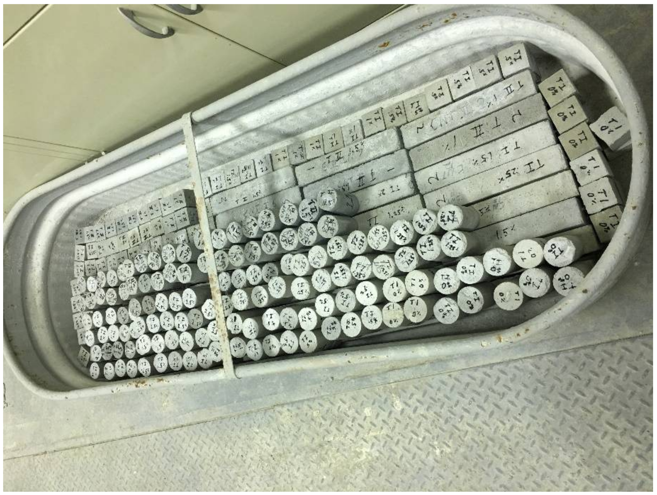
In order to cast LMM specimens, the required amount of CNTs was mixed with SBR. The chemical techniques involved the formation of weak (i.e., non covalent) or strong (i.e., covalent bond) to promote the dispersion process. In SBR latex, the presence of surfactants in the ingredients of the latex facilitated the dispersion through the formation of noncovalent Van der Waal bond between the surfactants and the CNTs. The multi-walled carbon nanotubes (MWCNTs) were used first dispersed in deionized water using ultrasonication for 30 min. The resulting MWCNTs–water mixture was added to the SBR latex and the suspension was ultrasonicated for 2 h. The dispersion procedures were utilized and analyzed previously by Soliman et al. [18], who showed a fair distribution of the CNTs in LMM. Later, the prepared mixture was used to make the CNT-LMM. Two mechanical mortar mixers were used to prepare all the mixes. A schematic for the CNTs dispersion and mortar mixing process is shown in Figure 1. The LMM specimens were cast in 50.8 mm wide × 50.8 mm high × 279.4 mm long prisms, 50.8 mm diameter × 101.6 mm high cylinders, and 50.8 mm × 50.8 mm × 50.8 mm cubes. The prisms are used to examine shrinkage and flexural response of different LMM mixes, while the cylinders and cubes are used to examine the tension and compression strengths respectively. The casted specimens were cured for 28 days before they were subjected to 300 cycles of two tests: thermal fatigue and freeze-thaw tests. A number of replicated specimens were created from each mixture and for each mode of testing. At least three replicas were tested at any given time, exposure, and loading conditions. Specimens were cured for 28 days. The curing regime included water curing for two days, followed by air curing for five days, and finally water curing for the remainder of 28 days. The specimens were submerged in lime water for 48 h before the freeze-thaw and thermal fatigue exposure. Figure 2 shows the curing of all the LMM specimens in water tank. More details about curing process can be found in ACI 548.3R, 2009.
2.2. Freeze-Thaw and Thermal Fatigue Cycles
To evaluate the durability of different LMM specimens with various CNTs contents, the specimens were subjected to both freeze-thaw cycling and thermal fatigue cycling tests. The freeze-thaw and thermal fatigue tests are proposed in this study to simulate the outdoor temperature changes during the winter and summer times, respectively. For both tests, LMM specimens were subjected to 300 cycles. For the freeze-thaw tests, the cycles were designed in accordance with ASTM C-666B. A freeze and thaw system was used in which the specimens were subjected to freezing-and-thawing cycles with temperature change from (−18 ± 2 °C) to (4 ± 2 °C). The duration for a single cycle was selected three hours following the ASTM standards recommendations, which suggest a duration between 2 and 5 h for each cycle during freeze-thaw testing. During the test, the specimens, which were surrounded by air, were cooled to (−18 ± 2 °C), and then pumped in the water around the specimens to thaw the specimens to (4 ± 2 °C). For the daily temperature cycling (thermal fatigue) test, the test temperature varied between 16 °C and 40 °C. For thermal fatigue, the chamber has a heating and cooling system in order to change the temperature from 40 °C to 16 °C and vice versa.
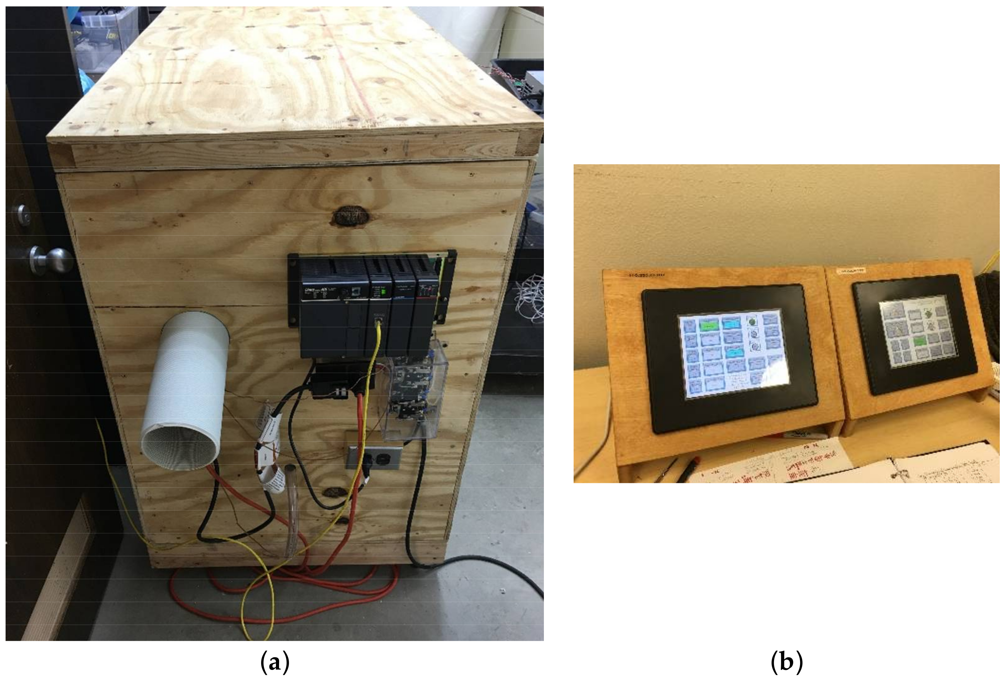
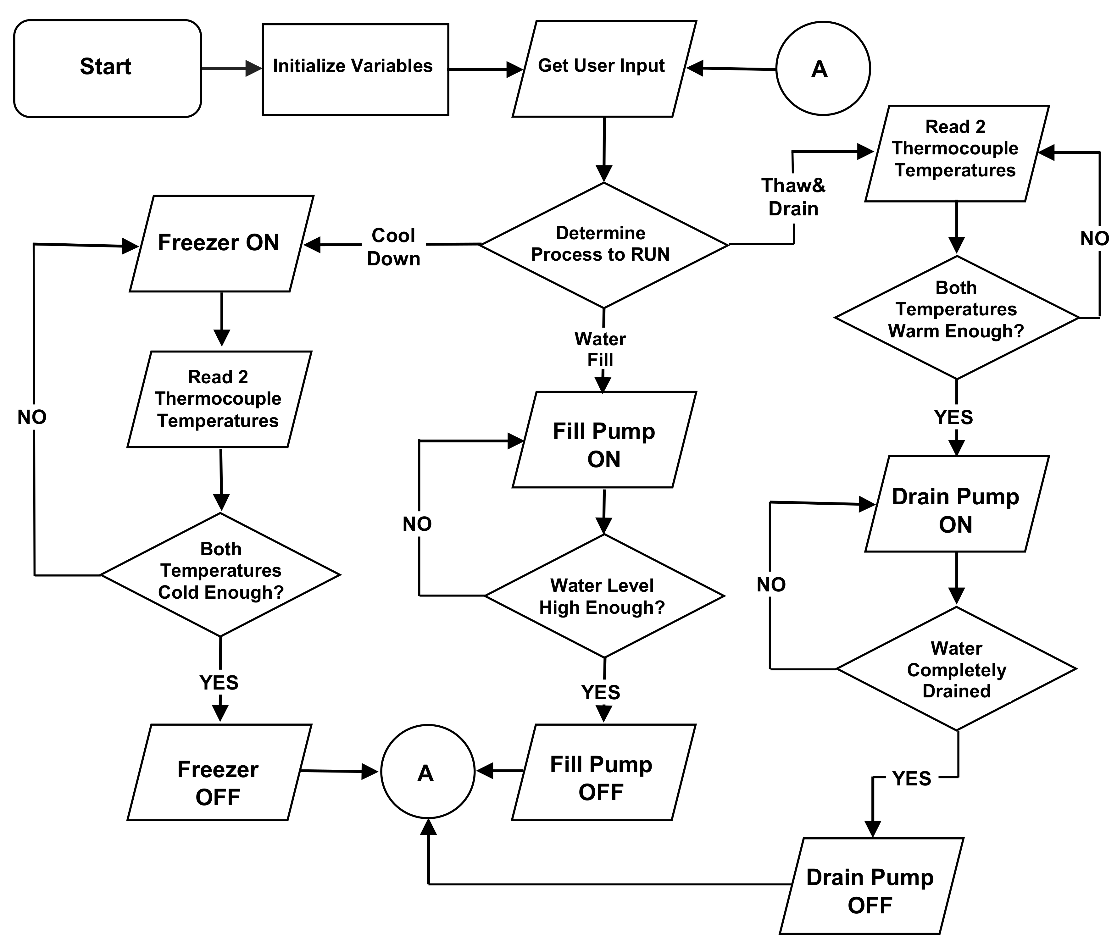
The thermal cycles were applied to LMM specimens in the environmental chamber facility at Ohio Northern University (Figure 3). For both tests, the temperature varying processes were controlled by a DirectLOGIC D4-450 PLC (programmable logic controller) (Koyo, PLC Direct, Cumming, GA, USA). The flow chart of the control program is shown in Figure 4. The user can set the upper and lower temperature limits, the water fill time, the delay before draining time, and the drain time before putting the PLC in automatic control mode. The program also provides a manual mode so that each of the process steps can be tested and adjusted before running the process in automatic mode. User input and process output was displayed on a C-more EA7-T8C 8-inch touchscreen. The touch screen displays the current temperatures of the two thermocouples that were used, along with indicators for the current operation in progress. Current water fill, freezer run, and water drain times along with the current cycle and last cycle times and cycle count are also displayed on the touch screen.
2.3. Physical and Mechanical Evaluations
The effect of thermal exposure on the mechanical and dimensional stability of different LMM specimens was evaluated through mechanical testing and shrinkage measurements. The compressive and tensile strength of cylinders and cubes were determined at 28 days of age of concrete and after exposing the specimens to freeze-thaw and thermal fatigue cycles. Mechanical testing samples was performed mid-way and at the end of freeze-thaw and thermal fatigue tests. The strength of each sample was measured, and then the average of the results of all the samples was reported. Statistical analysis was conducted on the test results to determine the significance difference due to the addition of CNTs and increasing the number of thermal cycles. The compression test was performed in accordance with ASTM C39 [23], whereas the splitting tensile test was performed in accordance with ASTM C496 [24]. The same standard testing machine was used to conduct both of the compression and tensile tests. To determine the effect of shrinkage on the LMM specimens, the length of the LMM was measured after every 30 cycles. The change in length is then used to compute the shrinkage strains that were induced due to the application of freeze-thaw and thermal fatigue cycles. A digital comparator was utilized to monitor the change in the length of LMM prisms. Finally, after all of the cycles were completed, the LMM prisms were tested in flexure to failure using an Instron® machine (Norwood, MA, USA) (Figure 5). The flexural test was performed in accordance with ASTM C348 [25]. The load was applied at the mid-span of each specimen with a supported length of 228.6 mm. The load and mid-span deflection was recorded and the load-deflection curves for different LMM specimens are presented and discussed.
3. Results and Discussion
3.1. Effect of CNTs Content on Compressive and Tensile Strengths
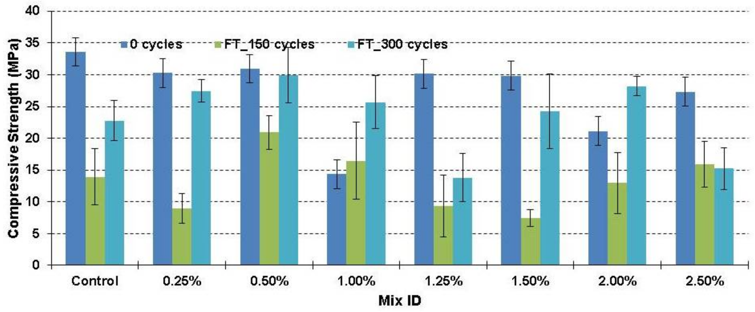
Figure 6 and Figure 7 presents the compressive strength of LMM specimens due to the freeze-thaw and thermal fatigue cycles, respectively. For simplification purposes, the LMM specimens that were tested for freeze-thaw are referred to as “FT”, while the LMM specimens that were tested for thermal fatigue are referred to as “TF”. For freeze-thaw testing, after 150 cycles, the LMM control specimens experienced a drastic drop in compressive strength of 58%; however, they regained part of the lost strength (26%) after 300 cycles. The drop in strength followed by a regain could be explained by two counteracting effects. First, the freeze and thaw cycles produces thermal strains that promote the development of microcracks, which in turn, reduces the compressive strength. The development of microcracks can be attributed to the internal hydraulic pressure caused by the frozen water inside the LMM specimens as reported earlier by (Cai et al. (1998)). On the other hand, the curing of overtime improves the mechanical properties. The development of microcracks seems to occur extensively in the first 150 freeze-thaw cycles leading to significant reduction in the compressive strength. The following 150 freeze-thaw cycles observe limited development and propagation of microcracks, leading to an increase in the compressive strength due to the continuous curing. The gain in compressive strength is owing to the late curing that took place beyond 150 cycles. The low permeability of LMM helped reduce the water loss from the mixtures and therefore contributed to the late curing of cement and latex films.
Similar trend was observed with most LMM specimens with different CNTs contents. However, the level of drop and regain in the compressive strength after 150 and 300 cycles differs with the use of CNTs. For instance, with the addition of 0.5% CNTs, the compressive strength drops by 32% after 150 cycles followed by an increase of 29% after 300 cycles. Similarly, with the addition of 2.0% CNTs, the compressive strength drops by 38% after 150 cycles followed by an increase of 72% after 300 cycles. The role of CNTs in limiting the development of microcracks is evident through the reduction in the drop in the compressive strength after 150 cycles and the increase in the regain in the compressive strength after 300 cycles is evident. In addition, it can be observed in most LMM specimens that the addition of CNTs increases the compressive strength when compared to the specimens without CNTs after the exposure to the same number of freeze-thaw cycles. This is evident with the addition of 0.5%, 1.0% and 2.5% due to the exposure to 150 cycles of freeze and thaw and also is evident with the addition of 0.25%, 0.5%, 1.0%, 1.5% and 2.0% due to the exposure to 300 cycles of freeze and thaw, as shown in Figure 6. It is therefore clear that adding small amount of CNTs shows superior effect as it improves the resistance of LMM to free-thaw cycles.
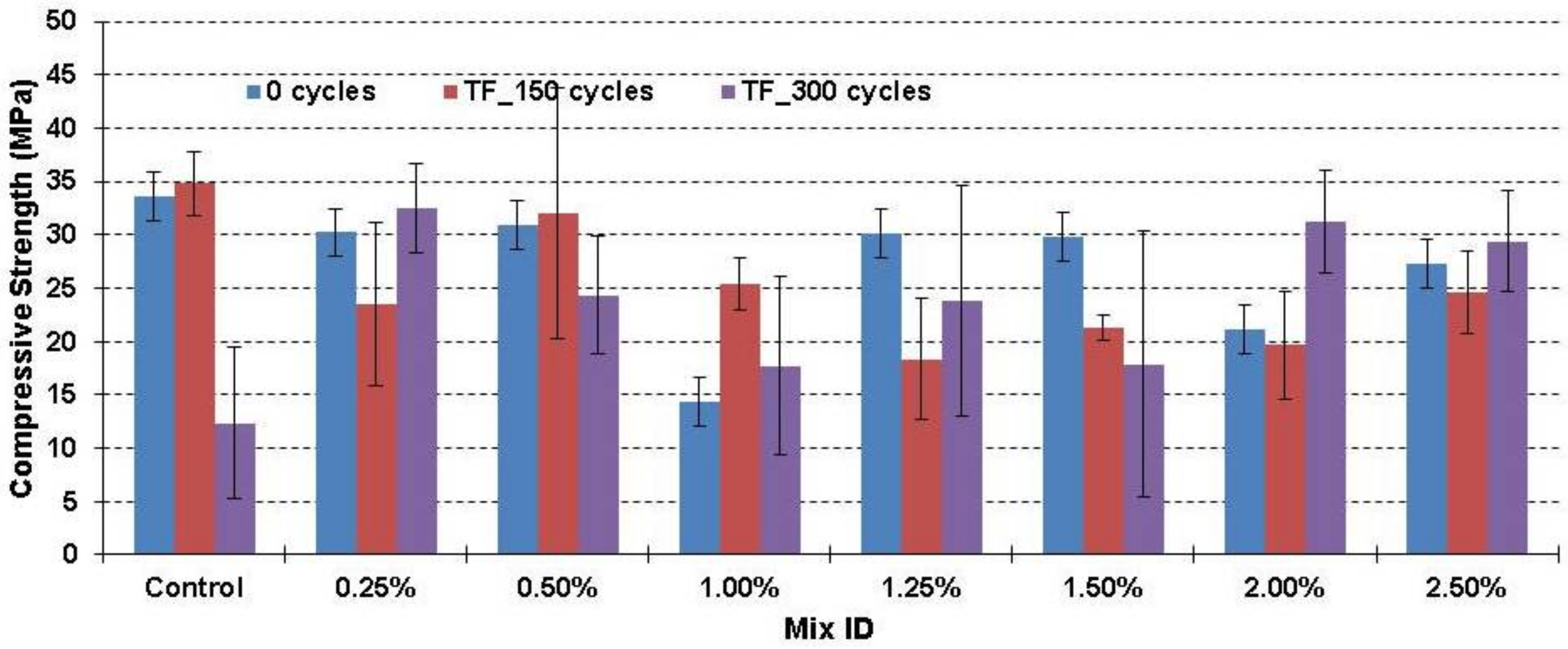
For thermal fatigue testing (Figure 7), the control LMM specimens observe no change in the compressive strength after the exposure to the first 150 cycles. In addition, the same specimens observed a drastic drop in the compressive strength (63%) after the exposure to the second 150 cycles. It is obvious that the development and propagation of microcracks due to thermal fatigue cycles is more extensive in the second 150 cycles, which differs from the freeze-thaw test observations. This is attributed mainly to the difference in the applied temperature range between the two tests. With the addition of CNTs to LMM specimens, the drop in the compressive strength after the exposure to 300 cycles is either reduced significantly or eliminated. Moreover, a noticeable increase in the compressive strength is observed with the addition of 0.25%, 2.0%, and 2.5%, as shown in Figure 7. Therefore, it is also evident that adding small amount of CNTs yields great improvements in both freeze-thaw and thermal fatigue. In general, the two tests have shown that LMM specimens with 0.25% and 2.0% CNTs showed the highest resistance to thermal cycles. The improvements reached 30% for FT and 40% for TF with the addition of 0.25% CNTs and 30% for FT and 50% for TF with the addition of 2.0% CNTs.
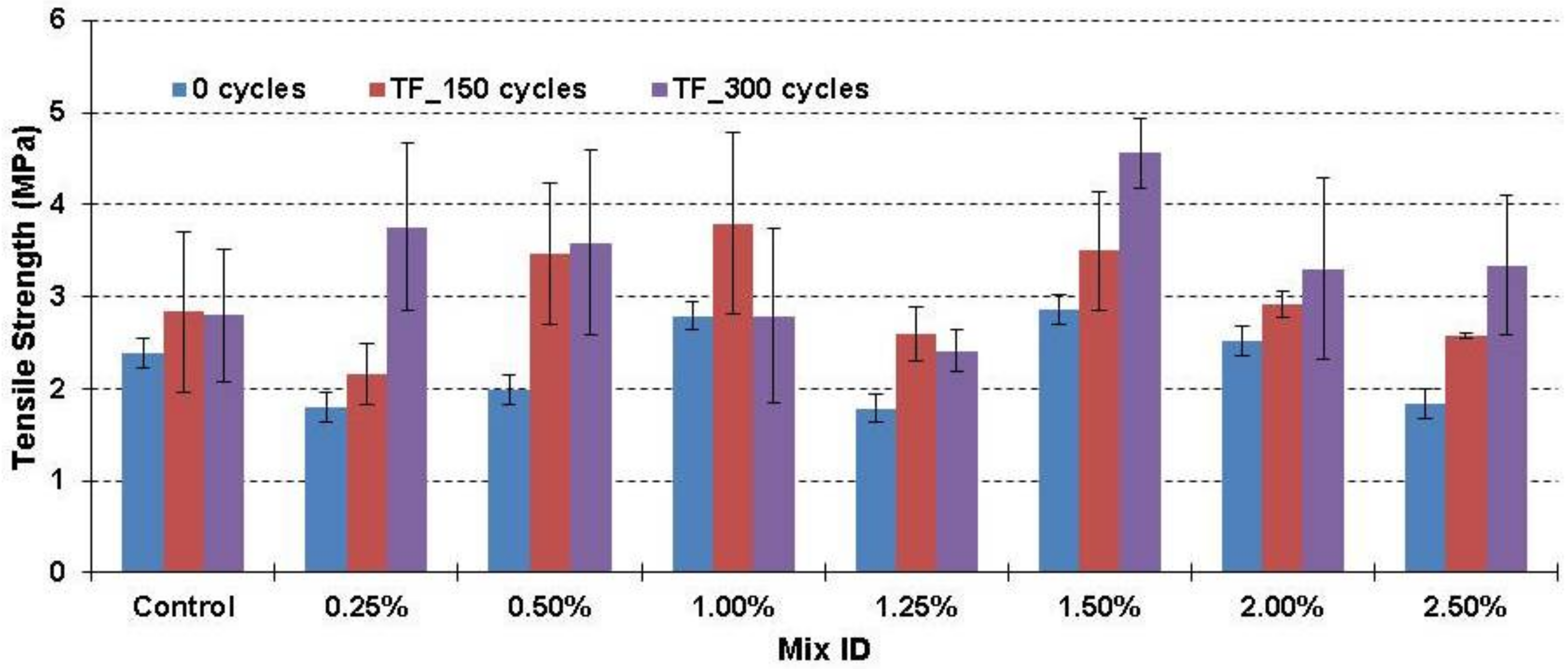
Figure 8 and Figure 9 present the tensile strength results of LMM samples due to freeze-thaw and thermal fatigue tests, respectively. Contrary to the compressive strength, limited or no drop in tensile strength is observed in all of the LMM specimens with the exposure of freeze-thaw and thermal fatigue cycles. The difference in the tensile and compressive behavior could be attributed to the difference failure mechanisms of the two tests. In tension, the development of single critical crack during failure suggests that the tensile strength depends on the local conditions of the crack location, and may have been little influenced by the global condition of LMM specimens after the thermal exposure. On the other hand, the compression fracture usually starts with the formation of multiple microcracks before macrocrack is developed, and therefore it is more susceptible to the global conditions of LMM specimens.
Many LMM specimens with CNTs demonstrated higher tensile strength than that of control LMM due to the exposure to freeze-thaw or thermal fatigue cycles. For instance, the addition of 0.25% CNTs increased the tensile strength of LMM by 44% and 46% after the exposure of 150 cycles and 300 cycles of freeze-thaw, respectively. Similarly, the addition of 1.5% CNTs yields 6% and 12% in the tensile strength after the exposure of 150 cycles and 300 cycles of freeze-thaw. The improvement in tensile strength in LMM specimens that were subjected to thermal fatigue cycles is more evident with the use of CNTs. Adding 0.25%, 0.5%, and 1.5% of CNTs increases the tensile strength by 20%, 75%, and 22% after the exposure to thermal fatigue cycles. The improvement in the tensile strength can be attributed to the bridging effect. The bridging effect is enhanced by two mechanisms. First, is the interfacial friction between the CNTs and the surrounding matrix. Second, the presence of noncovalent Van der Waal bond between the CNTs and the SBR latex.
3.2. Effect of CNTs Content on Shrinkage over Time
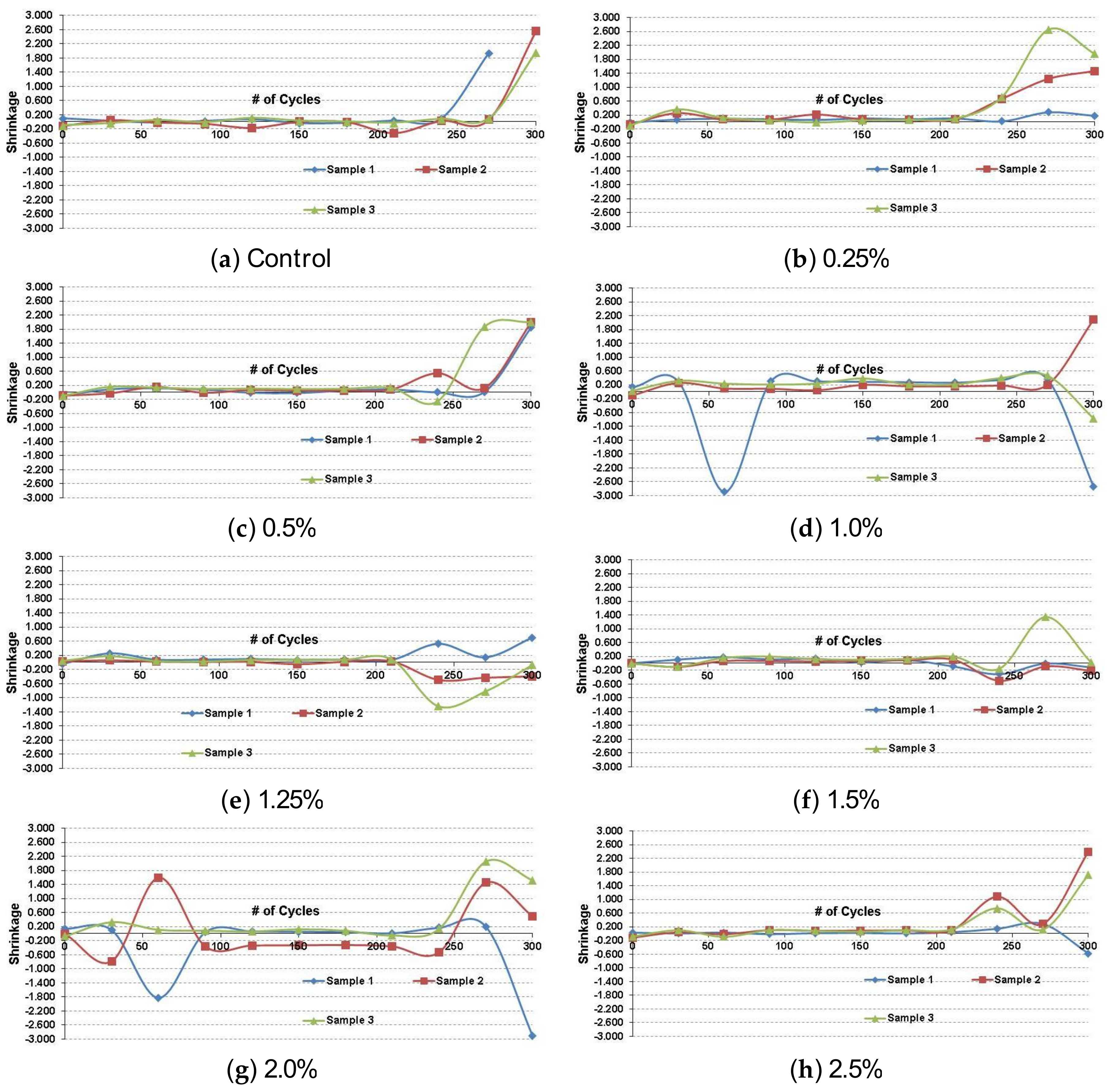
Figure 10 and Figure 11 present the shrinkage strain results of LMM samples due to the freeze-thaw and thermal fatigue tests, respectively. The change of the length of the samples due to the cycles was measured using a digital comparator at 30 cycle intervals. The change in length was then used to compute the shrinkage strains. In general, all of the LMM specimens observed shrinkage strains between −0.1% and +0.1% for freeze-thaw test. For the control sample, there was a noticeable increase in average shrinkage strain of 0.1% at 120 cycles. Later, the average shrinkage strains increased considerably to 0.2% beyond 210 cycles. A similar trend to that of the control sample was observed in LMM specimens with CNTs. LMM specimens with 0.5%, 1.25%, 1.5%, and 2.5% CNTs have shown thermal stability at 120 cycles since they experienced low shrinkage strains, as shown in Figure 10, however they observed significant increase in shrinkage strains beyond 210 cycles.
Lower shrinkage strains were observed with the exposure to thermal fatigue cycles. This observation applies to LMM control specimens as well as LMM specimens with CNTs. The LMM specimens observed shrinkage strains ranging between −0.1% and +0.1% due to the exposure to thermal fatigue cycles. The largest shrinkage strain was observed in LMM specimens with 1.0% CNTs. It can be deduced that the CNTs does not influence the development of shrinkage strain during the exposure to either freeze-thaw or thermal fatigue cycles. However, they provide additional mechanism for transferring the load, leading to improved compressive and tensile strengths, as observed in the compression and tension test evaluations.
3.3. Effect of CNTs Content on Flexural Behavior
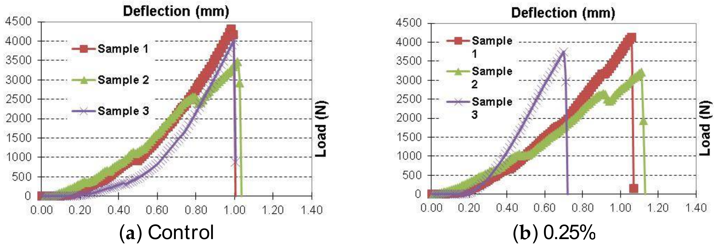
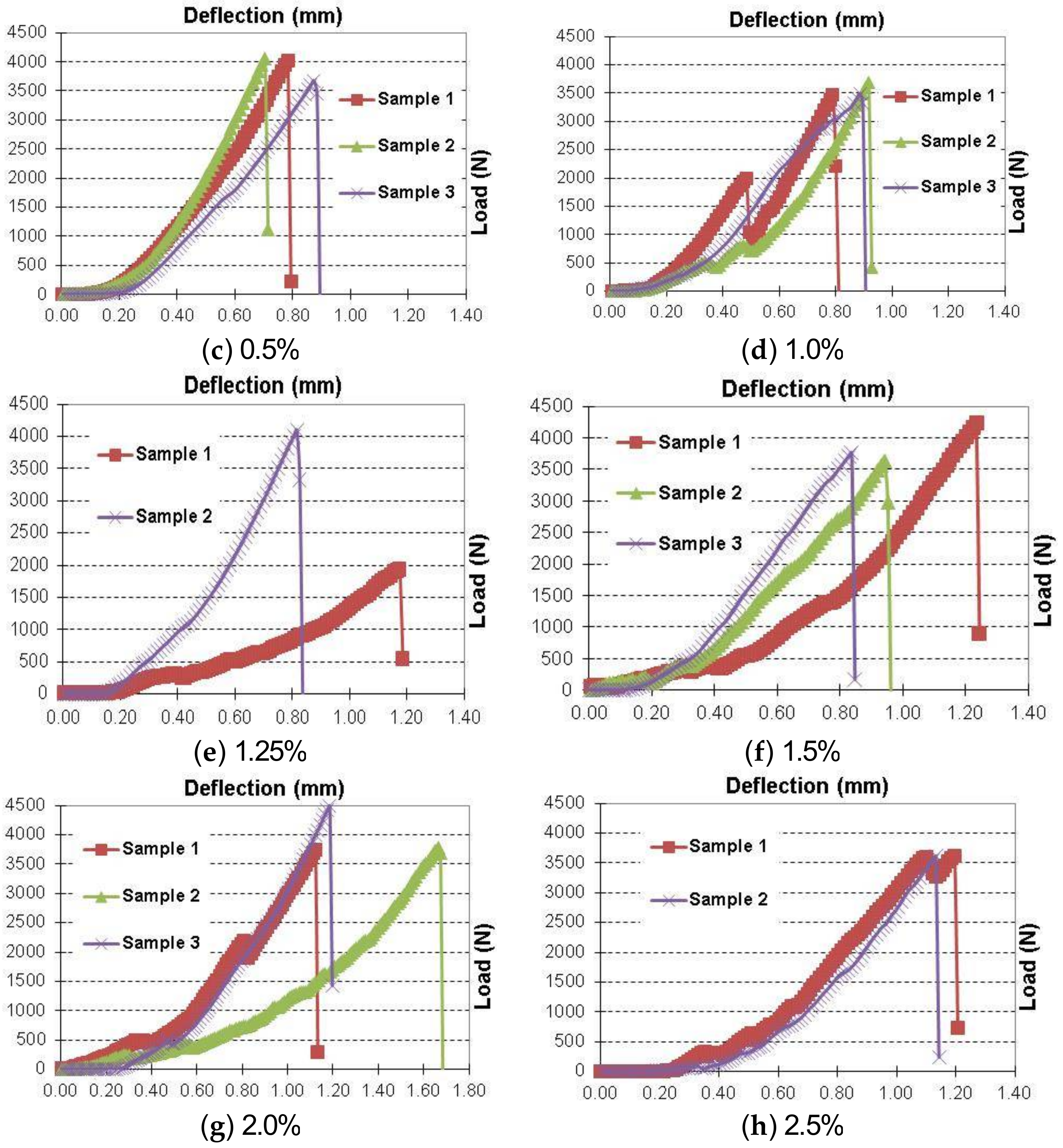
Figure 12 and Figure 13 present the load-deflection curves of LMM specimens tested in flexure after the exposure to 300 cycles of freeze-thaw and thermal fatigue, respectively. For the freeze-thaw test, the control specimens showed an average load carrying capacity of 2800 N. Adding CNTs to LMM mixtures slightly increased their load carrying capacity. LMM with 0.5%, 1.0%, 1.5%, and 2.0% observed average load carrying capacities of 2921 N, 2953 N, 2942 N, and 2955 N, which corresponds to improvements of 17.6%, 18.9%, 18.4%, and 19%, respectively, as shown in Figure 12. The observation in flexure load carrying capacity with the addition of CNTs stems from the improvement in the tensile strength observed earlier in splitting tension test since fracture of LMM prisms in bending is typically governed by the modulus of rupture. However, in addition to the tensile behavior, bending test also reveals more information about the ductility of different LMM mixture. In this context, moderate CNTs contents are found to contribute in improving the ductility and deformation capacity of LMM mixtures. This is apparent with the addition of 1.25%, 1.5%, and 2.0% CNTs, which observed 5%, 10%, and 15% increase in the average deflection at failure respectively.
For thermal fatigue test, the control specimens showed an average load carrying capacity of 4000 N, which is (30%) higher than that observed in the freeze-thaw test. Similar trend is also observed for LMM specimens with CNTs. This suggests that freeze-thaw cycles have more adverse effect on concrete than thermal fatigue cycles. The difference between the effect of freeze-thaw and thermal fatigue tests on compressive strength is attributed to the difference in the temperature exposure range. In freeze-thaw cycles, the temperature was altered between −18 °C to 4 °C, which helped to maintain water in the mixture for late curing. On the other hand, the temperature in the thermal-fatigue test was altered between 18 °C and 40 °C, which promoted water loss from the mixture and prevented the late curing and the regain in compressive strength. In addition, adding CNTs to LMM did not seem to have major effect on improving the load carrying capacity or ductility of specimens that were subjected to thermal fatigue cycles and tested in flexure. It is important to emphasize here that the physical characteristics of CNTs, such as the type of CNTs, aspect ratio, and specific surface area, are crucial factors that may affect the dispersion process of CNTs, and therefore may alter the effect of CNTs on the thermal stability and mechanical behavior of LMM specimens. Further research is warranted to examine other types of CNTs in LMM and mixtures.
4. Conclusions
A comprehensive investigation was conducted in order to examine the effect of CNTs on the freeze-thaw and thermal fatigue resistance of LMM specimens. CNTs contents weighing up to 2.5% of the weight of SBR latex are examined. LMM specimens were subjected to 300 cycles of freeze-thaw and thermal fatigue cycles before conducting mechanical and shrinkage evaluations. The mechanical evaluation consisted of testing LMM cubes, cylinder, and prisms in compression, tension, and bending, respectively. After conducting this research, the following conclusions are drawn:
- Freeze-thaw cycles adversely affect the compressive strength of LMM specimens due to the rapid development of microcracks in the first 150 cycles. The effect of freeze-thaw cycles is stabilized in the following 150 cycles, leading to relative rebound in the compressive strengths. The effect of thermal fatigue cycles is less pronounced on the compressive strength of different LMM specimens.
- Contrary to the compressive strength, the effect of freeze-thaw and thermal fatigue cycles on the tensile strength of LMM specimens was limited. This could be attributed to the difference in the failure mechanism of LMM specimens in compression and tension.
- It is apparent that adding CNTs improved the thermal resistance and freeze and thaw resistance of the produced LMM in compression. The role of CNTs here is evident in limiting the drop in compressive strength after the exposure to 150 cycles of freeze-thaw cycles and increasing the regain in compressive strength after the exposure to 300 cycles of freeze-thaw cycles. The CNTs effect is less evident in improving the compressive strength with thermal fatigue cycles.
- Large effect of using CNTs for improving the tensile strength of LMM specimens that were subjected to thermal fatigue cycles is observed. Similar improvements in tensile strength are observed for LMM specimens subjected to freeze-thaw cycles. By adding 1.5% CNTs, the improvements in the tensile strength reached 59% after the exposure to 300 cycles of thermal fatigue and 12% after the exposure to 300 cycles of freeze-thaw. The improvements in tensile strength could be attributed to the CNTs bridging effect. The bridging effect is supported by the friction and the noncovalent bond between the nanotubes and surrounding latex.
- Adding CNTs results in improvement in compressive strength and tensile strength of LMM. Improvement in tensile strength is due to bridging.
- The use of CNTs in LMM mixtures does not alter the shrinkage strains developed at LMM specimens when exposed to freeze-thaw or thermal fatigue cycles. However, they contribute in stress transfer as noticed in the compression and tension test results.
- Adding CNTs increased the flexural load carrying capacity and ductility of LMM specimens subjected to freeze-thaw cycles. Such improvements are found to be in line with the improvements in the tensile strength observed after conducting the splitting tension test.
Acknowledgments
The authors acknowledge Nathan Craft, Nathan Miller, Mike Kimberlin, and Scot Cottle at the Ohio Northern University for their help and support for the project.
Author Contributions
The authors contributed equally to this research and the paper preparation.
Conflicts of Interest
The authors declare no conflict of interest.
References
- Ohama, Y. Handbook of Polymer-Modified Concrete and Mortars: Properties and Process Technology; William Andrew: Norwich, NY, USA, 1995. [Google Scholar]
- ACI Committee 548. ACI 548.3R-09: Report on Polymer-Modified Concrete; ACI Committee: Farmington Hills, MI, USA, 2009. [Google Scholar]
- Sun, W.; Zhang, Y.M.; Yan, H.D.; Mu, R. Damage and Damage Resistance of High Strength Concrete Under the Action of Load and Freeze-Thaw Cycles. Cem. Concr. Res. 1999, 29, 1519–1523. [Google Scholar] [CrossRef]
- Mu, R.; Miao, C.; Luo, X.; Sun, W. Interaction between Loading, Freeze-Thaw Cycles, and Chloride Salt Attack of Concrete with and without Steel Fiber Reinforcement. Cem. Concr. Res. 2002, 32, 1061–1066. [Google Scholar] [CrossRef]
- Cai, H.; Liu, X. Freeze-Thaw Durability of Concrete: Ice Formation Process in Pores. Cem. Concr. Res. 1998, 28, 1281–1287. [Google Scholar] [CrossRef]
- Jacobsen, S.; Sellwvold, E.J. Self healing of high strength concrete after deterioration by freeze/thaw. Cem. Concr. Res. 1996, 26, 5–62. [Google Scholar] [CrossRef]
- Jacobsen, S.; Gran, H.C.; Sellevold, E.J.; Bakke, J.A. High strength concrete—Freeze/thaw testing and cracking. Cem. Concr. Res. 1995, 25, 1775–1780. [Google Scholar] [CrossRef]
- Gasman, L. Nanotechnology Applications and Markets; Artech House, Inc.: Norwood, MA, USA, 2006. [Google Scholar]
- Lee, J.; Mahendra, S.; Alvarez, P.J.J. Potential environmental and human health impacts of nanomaterials used in the construction industry. In Nanotechnology in Construction 3; Springer: Berlin/Heidelberg, Germany, 2009; pp. 1–14. [Google Scholar]
- Salemi, N.; Behfarnia, K.; Zaree, S.A. Effect of nanoparticles on frost durability of concrete. Asian J. Civ. Eng. 2014, 15, 411–420. [Google Scholar]
- Tyson, B.M.; Abu Al-Rub, R.K.; Yazdanbakhsh, A.; Grasley, Z. Carbon nanotubes and carbon nanofibers for enhancing the mechanical properties of nanocomposite cementitious materials. J. Mater. Civ. Eng. 2011, 23, 1028–1035. [Google Scholar] [CrossRef]
- Sobolkina, A.; Mechtcherine, V.; Khavrus, V.; Maier, D.; Mende, M.; Ritschel, M.; Leonhardt, A. Dispersion of carbon nanotubes and its influence on the mechanical properties of the cement matrix. Cem. Concr. Compos. 2012, 34, 1104–1113. [Google Scholar] [CrossRef]
- Wang, X.; Rhee, I.; Wang, Y.; Xi, Y. Compressive Strength, chloride permeability, and freeze-thaw resistance of MWNT concretes under different chemical treatments. Sci. World J. 2014, 2014. [Google Scholar] [CrossRef] [PubMed]
- Li, W.W.; Ji, W.M.; Wang, Y.C.; Liu, Y.; Shen, R.X.; Xing, F. Investigation on the mechanical properties of a cement-based material containing carbon nanotube under drying and freeze-thaw conditions. Materials 2015, 8, 8780–8792. [Google Scholar] [CrossRef] [PubMed]
- Cwirzen, A.; Habermehl-Cwirzen, K. The effect of carbon nano-and microfibers on strength and residual, cumulative strain of mortars subjected to freeze-thaw cycles. J. Adv. Concr. Technol. 2013, 11, 80–88. [Google Scholar] [CrossRef]
- Konsta-Gdoutos, M.S.; Metaxa, Z.S.; Shah, S.P. Highly dispersed carbon nanotube reinforced cement based materials. Cem. Concr. Res. 2010, 40, 1052–1059. [Google Scholar] [CrossRef]
- Soliman, E.M.; Kandil, U.F.; Taha, M.M.R. A New Latex Modified Mortar Incorporating Carbon Nanotubes: Preliminary Investigations; ACI Special Publications; ACI: Farmington Hills, MI, USA, 2011; Volume 278. [Google Scholar]
- Soliman, E.M.; Kandil, U.F.; Taha, M.M.R. The significance of carbon nanotubes on styrene butadiene rubber (SBR) and SBR modified mortar. Mater. Struct. 2012, 45, 803–816. [Google Scholar] [CrossRef]
- Ma, P.C.; Siddiqui, N.A.; Marom, G.; Kim, J.K. Dispersion and functionalization of carbon nanotubes for polymerbased nanocomposites: A review. Compos. Part A Appl. Sci. Manuf. 2010, 41, 1345–1367. [Google Scholar] [CrossRef]
- Glatkowski, P.J.; Landrau, N.; Landis, D.H.; Piche, J.W.; Conroy, J.L. Conformal Coatings Comprising Carbon Nanotubes. U.S. Patent Application No. 7118693B2, 10 October 2006. [Google Scholar]
- Kim, Y.J.; Shin, T.S.; Choi, H.D.; Kwon, J.H.; Chung, Y.C.; Yoon, H.G. Electrical conductivity of chemically modified multiwalled carbon nanotube/epoxy composites. Carbon 2005, 43, 23–30. [Google Scholar] [CrossRef]
- Yurekli, K.; Mitchell, C.A.; Krishnamoorti, R. Small-angle neutron scattering from surfactant-assisted aqueous dispersions of carbon nanotubes. J. Am. Chem. Soc. 2004, 126, 9902–9903. [Google Scholar] [CrossRef] [PubMed]
- ASTM International. ASTM C39/C39M-16b, Standard Test Method for Compressive Strength of Cylindrical Concrete Specimens; ASTM International: West Conshohocken, PA, USA, 2016. [Google Scholar]
- ASTM International. ASTM C496/C496M-11, Standard Test Method for Splitting Tensile Strength of Cylindrical Concrete Specimens; ASTM International: West Conshohocken, PA, USA, 2004. [Google Scholar]
- ASTM International. ASTM C348-14, Standard Test Method for Flexural Strength of Hydraulic-Cement Mortars; ASTM International: West Conshohocken, PA, USA, 2014. [Google Scholar]
Figure 1.
Schematic for the carbon nanotubes (CNTs)-latex modified mortar (LMM) preparation.
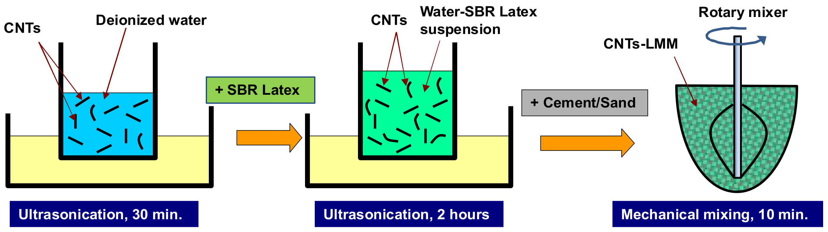
Figure 2.
Curing LMM specimens inside the water tank.

Figure 3.
Environmental chamber test setup (a) Controller attached to box chamber and (b) snapshot of the touchscreen.
Figure 3.
Environmental chamber test setup (a) Controller attached to box chamber and (b) snapshot of the touchscreen.

Figure 4.
A sample of flow chart of control program.

Figure 5.
Flexural Test Setup.
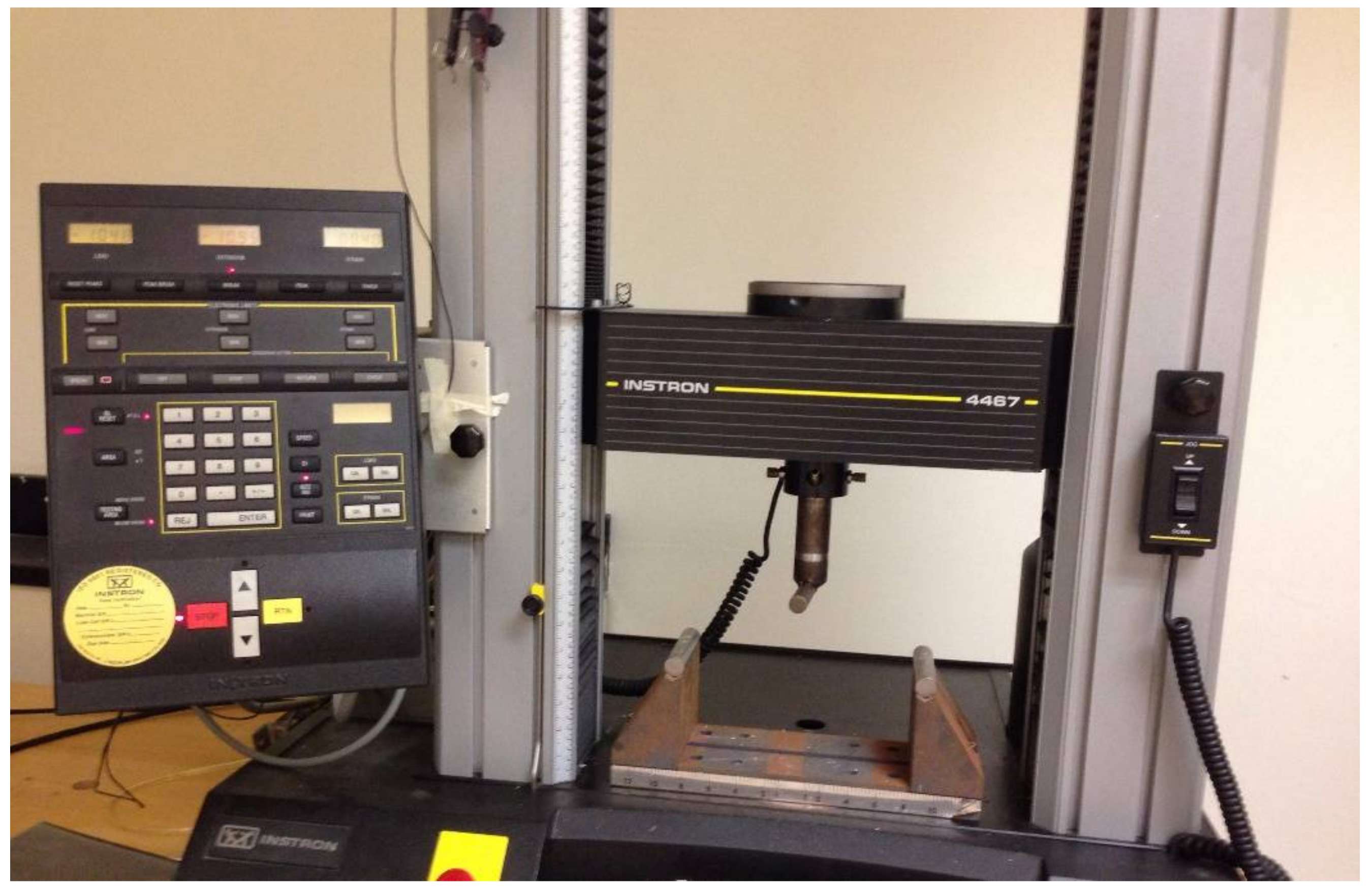
Figure 6.
Compressive Strength Results due to Freeze and Thaw Cycles.

Figure 7.
Compressive Strength Results due to Thermal Fatigue Cycles.

Figure 8.
Tensile strength results due to freeze and thaw cycles.
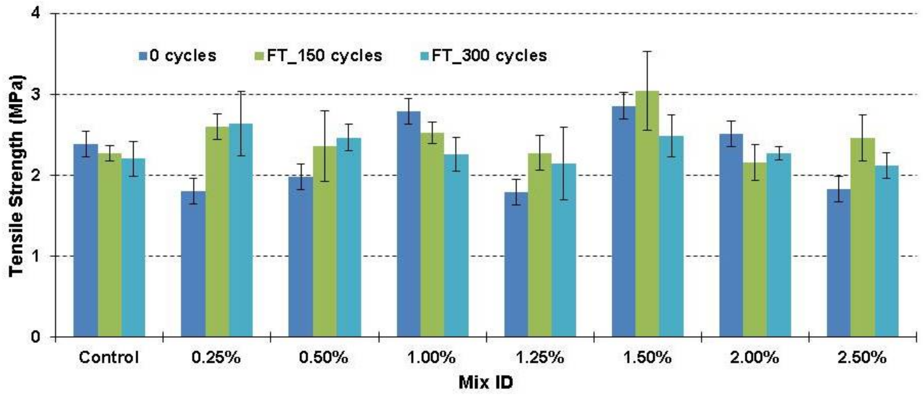
Figure 9.
Tensile strength results due to thermal fatigue cycles.

Figure 10.
Shrinkage results due to freeze and thaw cycles.

Figure 11.
Shrinkage results due to thermal fatigue cycles.
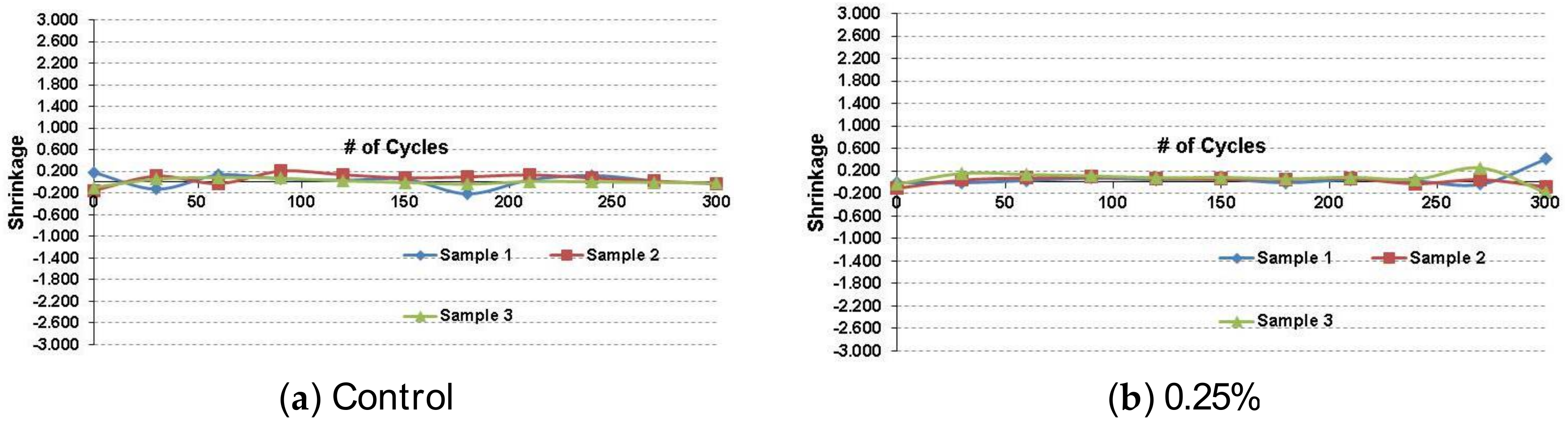
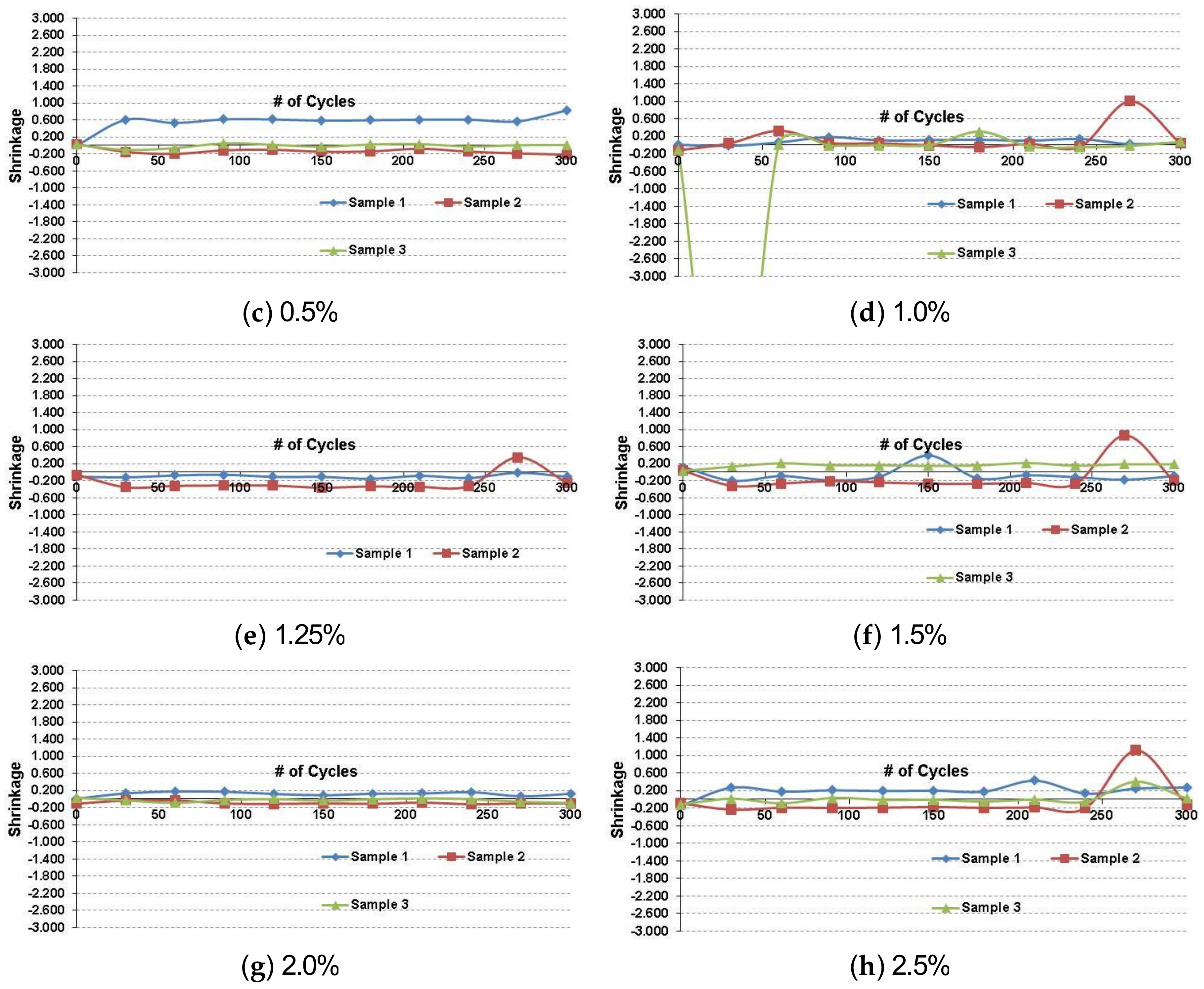
Figure 12.
Load-deflection relationships due to freeze and thaw cycles.
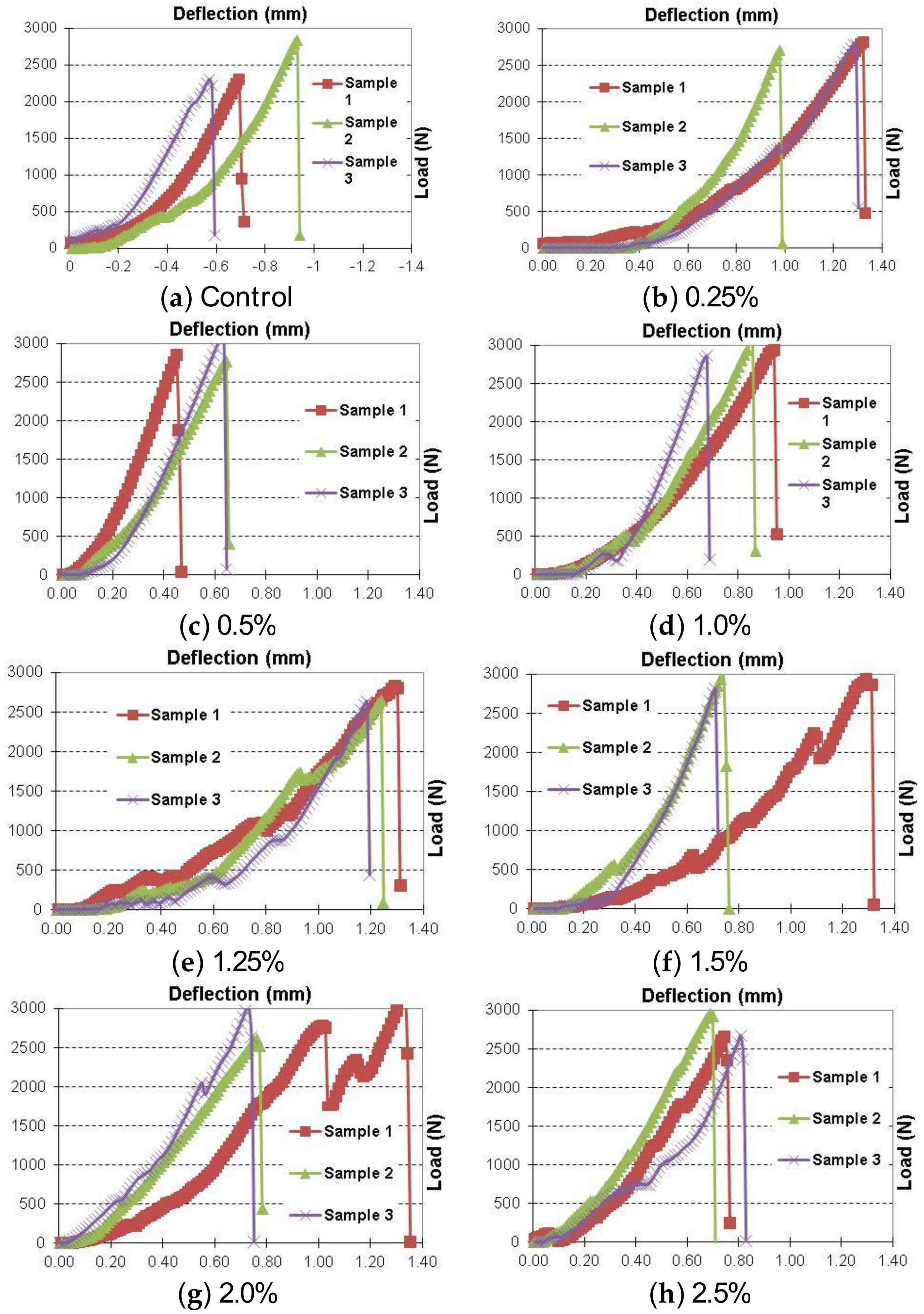
Figure 13.
Load-deflection relationships due to thermal fatigue cycles.


Table 1.
Mixture Proportions.
| Mix ID | Portland Cement (kg/m3) | Sand (kg/m3) | Water (kg/m3) | SBR-Latex (kg/m3) | CNT (kg/m3) |
|---|---|---|---|---|---|
| LMM—0% | 530.2 | 1457.7 | 203.4 | 79.5 | 0 |
| LMM—0.25% | 530.2 | 1457.7 | 203.4 | 79.5 | 0.2 |
| LMM—0.50% | 530.2 | 1457.7 | 203.4 | 79.5 | 0.4 |
| LMM—1.00% | 530.2 | 1457.7 | 203.4 | 79.5 | 0.8 |
| LMM—1.25% | 530.2 | 1457.7 | 203.4 | 79.5 | 1.0 |
| LMM—1.50% | 530.2 | 1457.7 | 203.4 | 79.5 | 1.2 |
| LMM—2.00% | 530.2 | 1457.7 | 203.4 | 79.5 | 1.6 |
| LMM—2.50% | 530.2 | 1457.7 | 203.4 | 79.5 | 2.0 |
© 2018 by the authors. Licensee MDPI, Basel, Switzerland. This article is an open access article distributed under the terms and conditions of the Creative Commons Attribution (CC BY) license (http://creativecommons.org/licenses/by/4.0/).
Share and Cite
MDPI and ACS Style
Abdel-Mohti, A.; Soliman, E.; Shen, H. Effect of Adding Carbon Nanotubes on the Freeze-Thaw and Thermal Fatigue Resistance of Latex Modified Mortar. Fibers 2018, 6, 19. https://doi.org/10.3390/fib6020019
AMA Style
Abdel-Mohti A, Soliman E, Shen H. Effect of Adding Carbon Nanotubes on the Freeze-Thaw and Thermal Fatigue Resistance of Latex Modified Mortar. Fibers. 2018; 6(2):19. https://doi.org/10.3390/fib6020019
Chicago/Turabian StyleAbdel-Mohti, Ahmed, Eslam Soliman, and Hui Shen. 2018. "Effect of Adding Carbon Nanotubes on the Freeze-Thaw and Thermal Fatigue Resistance of Latex Modified Mortar" Fibers 6, no. 2: 19. https://doi.org/10.3390/fib6020019
Note that from the first issue of 2016, this journal uses article numbers instead of page numbers. See further details here.