Fabrication of Shatter-Proof Metal Hollow-Core Optical Fibers for Endoscopic Mid-Infrared Laser Applications


1
National Institute of Technology, Sendai College, Sendai 989-3128, Japan
2
Headquarters, Miyagi Gakuin, Sendai 981-8557, Japan
3
School of Information Science and Engineering, Fudan University, Shanghai 200433, China
4
Graduate School of Biomedical Engineering, Tohoku University, Sendai 980-8579, Japan
*
Author to whom correspondence should be addressed.
Fibers 2018, 6(2), 24; https://doi.org/10.3390/fib6020024
Submission received: 27 March 2018
/
Revised: 13 April 2018
/
Accepted: 14 April 2018
/
Published: 18 April 2018
(This article belongs to the Special Issue Hollow Core Optical Fibers)
Abstract
:A method for fabricating robust and thin hollow-core optical fibers that carry mid-infrared light is proposed for use in endoscopic laser applications. The fiber is made of stainless steel tubing, eliminating the risk of scattering small glass fragments inside the body if the fiber breaks. To reduce the inner surface roughness of the tubing, a polymer base layer is formed prior to depositing silver and optical-polymer layers that confine light inside the hollow core. The surface roughness is greatly decreased by re-coating thin polymer base layers. Because of this smooth base layer surface, a uniform optical-polymer film can be formed around the core. As a result, clear interference peaks are observed in both the visible and mid-infrared regions. Transmission losses were also low for the carbon dioxide laser used for medical treatments as well as the visible laser diode used for an aiming beam. Measurements of bending losses for these lasers demonstrate the feasibility of the designed fiber for endoscopic applications.
1. Introduction
Mid-infrared lasers are increasingly being used in medical applications because mid-infrared light is strongly absorbed by the water, proteins, and lipids in human tissue. Mid-infrared lasers can be used in combination with a flexible endoscope or catheter for minimally invasive treatments of tumors and other diseased tissue. Such applications require an optical fiber that is sufficiently thin and flexible for insertion into the working channel of endoscopes or thin catheters. The fiber must also be able to deliver laser light to the target tissue with minimal transmission loss.
Common silica-glass fibers cannot transmit mid-infrared light with wavelengths longer than 2 μm because of absorption in the silica-glass material [1], so many types of infrared optical fibers have been developed, such as chalcogenide-glass fibers [2,3], metal-halide polycrystalline fibers [4,5], and hollow-core optical fibers [6,7]. Hollow-core optical fibers that confine light in an air core have some advantages over solid-core fibers for high-power laser delivery. Two types of hollow-core optical fibers have been developed so far. One is composed of glass capillary tubing with a silver film on the inside and a dielectric thin film on top of the silver [7,8,9] and this type of fiber is already used in medical applications [10]. The other is made entirely of glass and utilizes photonic crystal structures to confine light in the central air core [11,12].
Recently, an endoscopic submucosal dissection (ESD) process using a carbon dioxide (CO2) laser has been developed for treating early-stage gastric cancer [13], and this process uses a hollow-glass optical fiber to deliver the CO2 laser light. ESD is performed using a fiber (inner diameter 700 μm, length 2.65 m) that transmits laser light with power up to 12 W. When using such a common hollow-core optical fiber for endoscopic applications, a surgeon must be careful not to break the fiber by bending it too sharply because the breakage may scatter small glass fragments inside the body. This damage could be fatal. Glass shards can be avoided by using plastic tubing for the hollow-core optical fiber [14,15,16], but the power capacity of plastic-based hollow fibers is usually lower than that of glass-based fibers, especially when the fiber is bent.
Temelkuran et al. have developed a hollow waveguide with polymer dielectric multilayers that confines light by Bragg reflection [17]. Although this type of fiber transmits CO2 laser light of relatively high power with low losses [18], the chalcogenide material used for cladding may cause trouble in endoscopic applications.
Another option for fabricating a robust and flexible hollow-core optical fiber is to use metal tubing as the base material [19,20]. However, the inner surface of metal tubing is usually much rougher than that of glass tubing, even after chemical etching. This roughness causes scattering loss of the transmitted light. In clinical applications of infrared lasers, delivery of a visible targeting laser beam along with mid-infrared laser is necessary to make the irradiated spot visible to the surgeon. When the inner surface of the hollow core is relatively rough, the visible light is strongly scattered and does not form a targeting dot.
In this paper, we propose a fabrication method for a stainless steel hollow-core optical fiber for mid-infrared light. To reduce the roughness of the tubing inner surface, a polymer base layer is formed before depositing a silver film. This base coating smooths the surface, and as a result, the transmission loss is reduced for both CO2 laser light and visible light.
2. Material and Methods
Figure 1 shows a schematic of the proposed hollow-core optical fiber based on stainless-steel (SUS) tubing. The fiber begins as commercially available SUS tubing with an electrochemically polished inner surface. Although the root-mean-square (RMS) roughness of the surface is as low as 0.3 to 0.9 μm, it still causes scattering losses, especially for visible light. To smooth the inner surface of the SUS tubing, we form a relatively thick base coat of polymer on the surface. Then, a silver (Ag) film is coated on top of the base layer using the silver mirror reaction. Then, another polymer layer is formed on the top of silver layer and functions as an optical interference film. This polymer needs to be transparent to mid-infrared light since this layer optically functions as a dielectric film, so we use cyclic olefin polymer (COP) [21].
As the base-coating material, a commonly used two-liquid-reaction acrylic-silicone resin (AlcoSP, NATOCO, Aichi, Japan) was chosen. We chose this material partly because we found that it gives excellent adhesion to the silver film formed on top of the base coating [22]. The resin solution was made to flow through the SUS tubes (inner/outer diameter 550/780 μm) at 8 cm/min. Then nitrogen gas was flushed through the tubes at the rate of 50 mL/min for 1 h at room temperature to dry the resin coating. By this coating process, the resin film with a thickness of around 0.5 μm is formed. When forming the acrylic-silicone resin film, we found that re-coating several thin films yields a smoother surface than the thick film formed with a single coating. Based on the results of preliminary experiments, we chose a resin concentration of 45.5 wt % for the resin base coating.
Before the silver coating process, the surface of the resin layer was sensitized with SnCl2 solution to increase the adhesion of Ag film. A silver film was formed on the base coat by passing silver nitrate solution and reducing solution through the tube for 3 min. In the next step, we formed a COP thin film on the top of silver layer. The silver layer is usually only around 0.2 μm thick, so the cyclohexane solvent used to dissolve the COP may penetrate to the base layer through the thin silver film. In a preliminary test of whether the cyclohexane solvent damages the base coat, we removed the COP layer using cyclohexane and formed the COP again, comparing the loss spectra of the first and second COP-coated fibers.
In the measurement of the loss spectra in the visible to near-infrared region from 0.4 to 1.6 μm wavelength, of the fabricated fibers (550 μm inner diameter and 1 m length), an optical spectrum analyzer was used (AQ6315A, Yokogawa, Tokyo, Japan). Light from a halogen lamp was coupled to the fiber through a multimode silica-glass fiber with a core diameter of 400 μm. The output light from the tested fiber was then delivered to the spectrum analyzer using a silica-glass fiber with a core diameter of 600 μm. For measurement of the loss spectra in the mid-infrared region (2–12 μm), we used a Fourier transform infrared spectroscope (FT-IR) (FT/IR-350, JASCO, Tokyo, Japan). In this measurement setup, light from the FT-IR was coupled to the measured fiber by focusing the light with an off-axis mirror of focal length 50 mm. The light output from the fiber was detected using a liquid N2-cooled HgCdTe detector (MCT, JASCO, Tokyo, Japan).
Bending losses of the fabricated fibers were measured with a CO2 laser (LezawinCHS, J. MORITA, Kyoto, Japan) of wavelength 10.6 μm and a green laser diode with wavelength of 532 nm. In the experiment, the laser light was firstly injected into a short hollow-core optical fiber (length 15 cm, inner diameter 530 μm) that functions as a mode filter. The tested fibers were butt-coupled to this short fiber. In the bending test, the first 25 cm of the fiber was kept straight, and the middle part was bent to different bending angles with a bending radius of 20.25 cm. The output power was measured with a laser power meter.
3. Results and Discussion
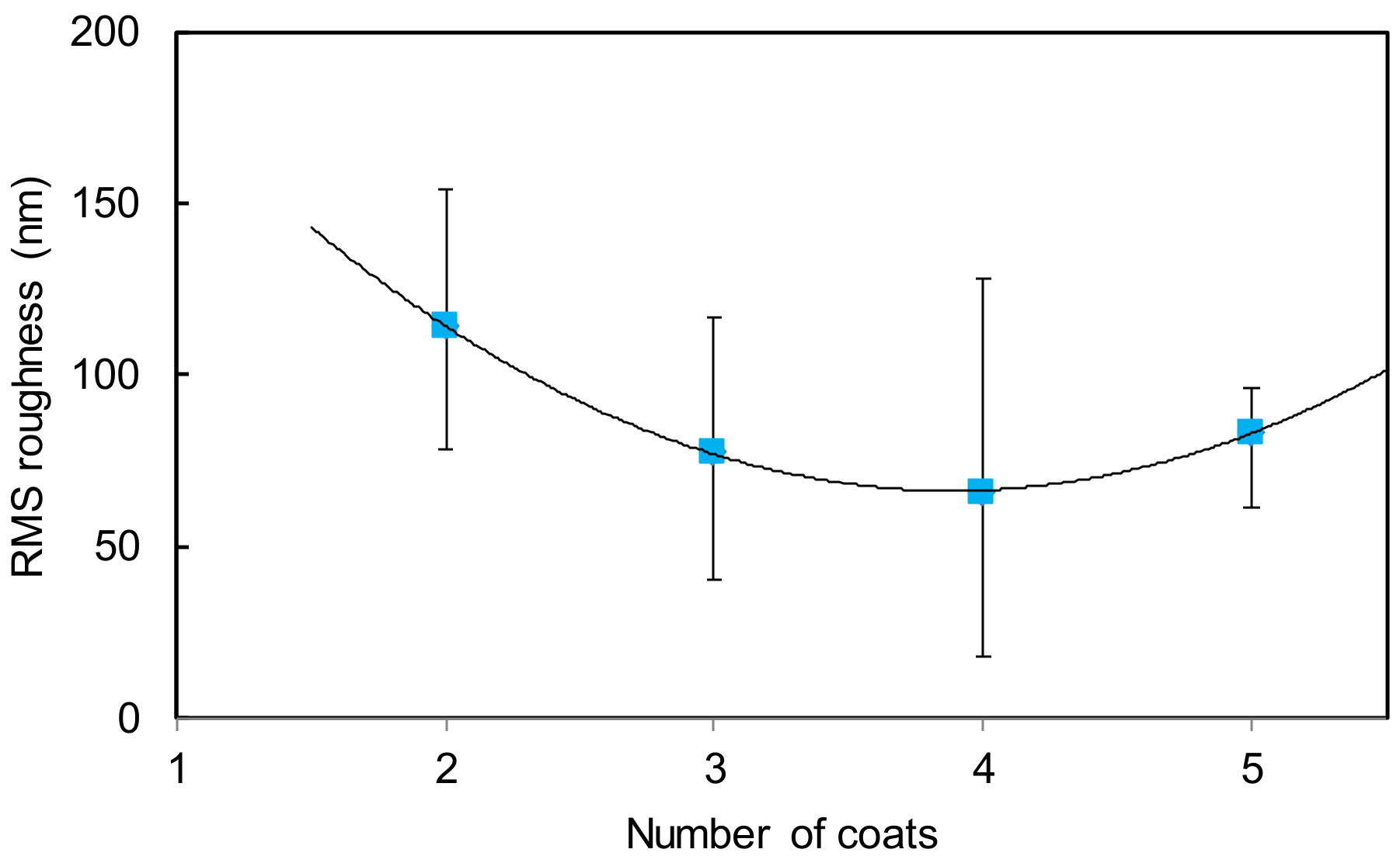
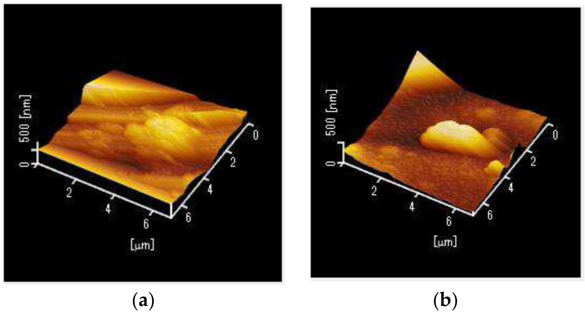
Figure 2 shows the surface roughness of the films as observed by an atomic force microscope (AFM) (AFM5100N, Hitachi, Tokyo, Japan) with two and four base coats applied. For this observation, we made samples by cutting base-coated SUS tubes into small pieces. The roughness of different points were measured 5–12 times for each sample, and the mean values, excluding the maximum and minimum values, are plotted in the figure. The error bars show the uncertainty in the measurements. The RMS roughness of the inner surface of the original SUS tube was as large as 0.6–0.9 μm, and it was made drastically smoother by the base coat. One can see that the roughness decreased with each thin film coat, and we found that the minimum mean roughness of around 70 nm was obtained with four coats. Figure 3 shows typical AFM images of the inner surfaces of SUS tubing after applying two and four re-coatings. One can see that the inner surface of the SUS tubing was smoothed by applying the resin base coating. As mentioned above, the thickness of the resin coating formed by a single process is around 0.5 μm and thus, the total thickness of the film formed by four re-coatings is around 2 μm.
Figure 4 shows changes in the loss spectra in the visible to near-infrared regions of fibers fabricated with the COP film. In this experiment, light from white light source was coupled to the hollow optical fibers via a graded-index, silica-glass fiber. When such an incoherent light is injected into a hollow optical fiber, many high-order modes are excited in the fiber and as a result, the attenuation losses become high such as shown in Figure 5a. Firstly a COP film was formed on the Ag layer and the loss spectrum was measured. Then the COP film was removed using cyclohexane solvent, and another COP film was formed on the Ag after the solvent was evaporated. We observed clear interference peaks resulting from the high uniformity of the COP film in both spectra, which shows that the acrylic-silicone base coating is not affected by the cyclohexane solvent. These clear interference fringes allow low transmission loss of the visible-wavelength target laser. In this figure, the loss spectrum of a fiber without COP film is also shown for comparison. Please note that losses of the fiber without COP film are lower than those with COP film in visible and near-infrared region. This is because silver itself provides a high reflectance in visible region and the COP coating on the top of silver somewhat reduce the reflectance of silver. However, in mid-infrared region, this relationship is inverted because silver does not show a high reflectance in the mid infrared and therefore, the COP film is essential for the fibers to obtain a low transmission loss for mid-infrared lasers.
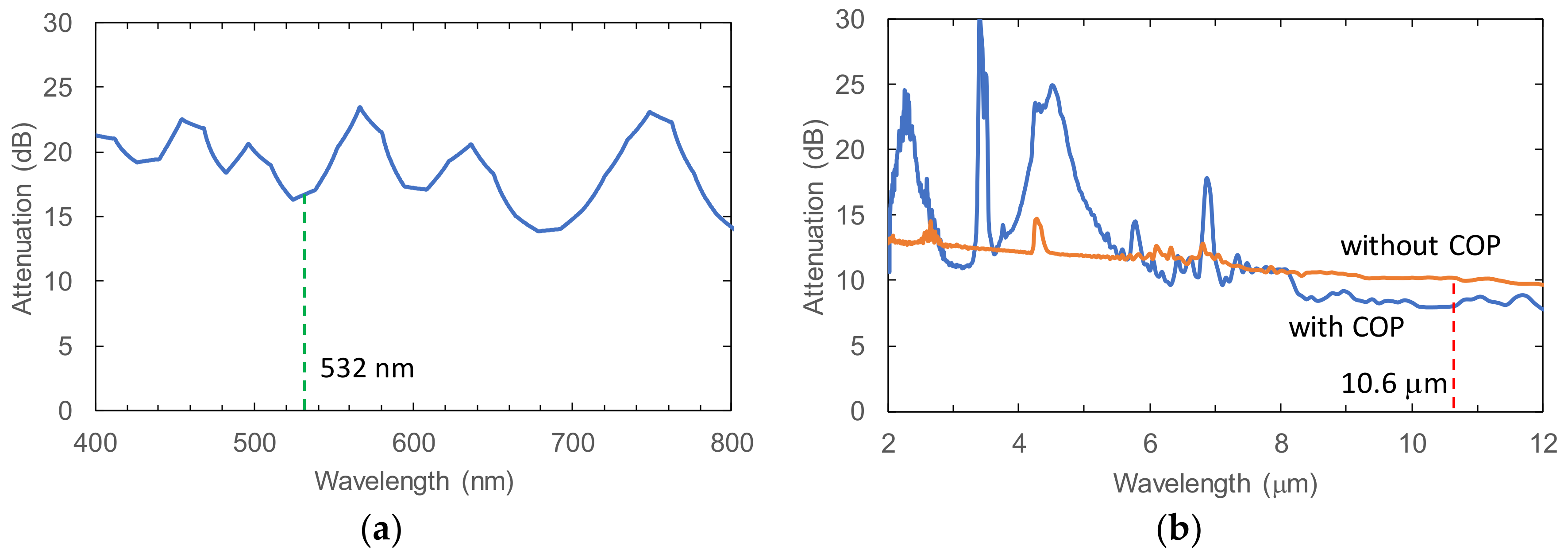
Figure 5a shows an example attenuation-loss spectrum of the COP-coated hollow-core optical fiber based on SUS tubing, measured in the visible region. The thickness of the COP film was finely tuned to match the interference fringe with the target wavelength of 532 nm that is used as the visible aiming beam of the medical CO2 laser system. The thickness of COP film as estimated from the spectrum was 0.97 μm. Figure 5b is the loss spectrum of the COP-coated fiber measured in the mid-infrared region. The loss spectrum of a fiber without COP film is also shown for comparison. We confirmed that, with a COP film of the above thickness, two interference peaks appear around 2.2 μm and 4.4 μm and that a low-loss region was obtained owing to the interference effect of the COP film in the wavelength region of 9–11 μm. Although some sharp absorption peaks appear for the COP in the mid-infrared region, we confirm that no peak appears at the CO2 laser wavelength of 10.6 μm.
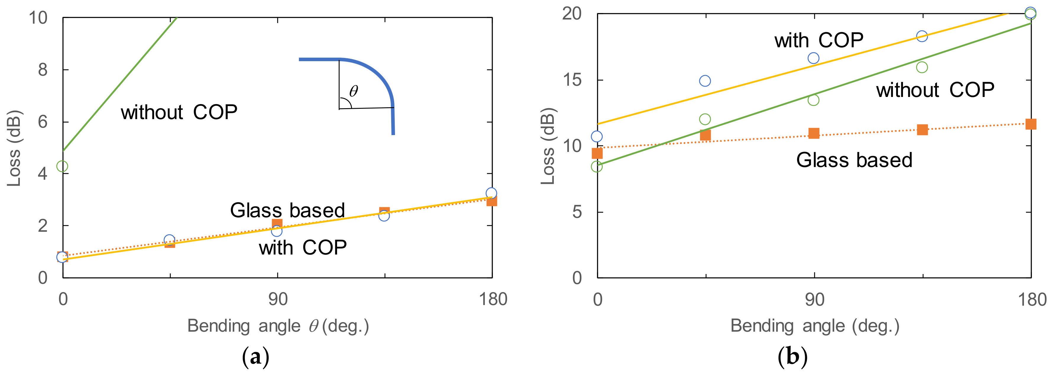
Figure 6 shows the bending losses of the COP-coated fibers based on SUS tubing measured with (a) a 10.6-μm CO2 laser and (b) a 532-nm laser diode. In this test, the laser light was coupled to the measured fiber via a short (15-cm long) hollow optical fiber. As mentioned above, this short fiber tip was used as a mode coupler to eliminate high-order modes. As a result, the low order modes are efficiently excited in the measured fiber and therefore, the measured losses become much lower than those in the loss spectra (Figure 4 and Figure 5) measured with an incoherent light.
In Figure 6a,b, the measured bending losses of a COP-coated fiber based on silica-glass capillary tubing are also shown for comparison. For mid-infrared CO2 laser light (Figure 6a), the straight loss of the COP-coated fiber was 0.75 dB. This loss increases to 3.2 dB when the fiber is bent 180 degrees. The measured losses of the SUS fiber coincide with those of the silica-glass based fiber. This result confirms that the acrylic-silicone resin coating functions well as a base layer that smooths the inner surface of SUS tubing. The losses of the fiber without a COP layer are much higher than the COP-coated fiber, and therefore, we find that a highly uniform COP layer is formed inside the SUS tubing with the help of the resin base coating.
For the visible laser, as shown in Figure 6b, the transmission loss is increased by the COP film formed on top of the silver layer because the reflection of silver is itself very high in the visible region. However, we confirm that the COP film does not largely affect the bending loss when the thickness is optimized, as shown in Figure 5a. Although the loss in the 180-degree bent fiber is as high as 20 dB, the green light transmitted through the fiber was clearly visible, confirming the feasibility of a COP-coated fiber based on SUS tubing for endoscopic applications in which a visible beam is needed at the target end. We also performed mechanical bending tests for samples of the fabricated fibers. The results of bending tests showed that the minimum elastic bending radius is 85 mm and that the fiber starts to snap at a bending radius of 2.5 mm.
The measured losses shown in Figure 6 are summarized in Table 1. Comparing the losses of the SUS-based and the glass-based fibers with COP coating, the losses of the SUS-based fibers are still larger than those of the glass-based fibers for the wavelength of 532 nm because of the larger inner-surface roughness of the SUS-based fibers (70 nm in RMS for the SUS-based fibers and 10 nm in RMS for the glass-based fibers). However, for the mid-infrared laser with a longer wavelength of 10.6 μm, the effect of roughness becomes smaller and the SUS-based fibers show low losses that are comparable to those of the glass-based fibers.
4. Conclusions
We have proposed a fabrication method for a robust and thin hollow-core optical fibers based on SUS tubing. This fiber is sufficiently flexible and optically robust for endoscopic mid-infrared laser applications. To reduce the inner surface roughness of the SUS tubing, we formed a polymer base layer before depositing silver and optical-polymer layers. By re-coating the resin base layer, the inner surface of the SUS tubing was made smooth enough for an effective optical layer to be formed. Clear interference peaks were observed in both the visible and the mid-infrared regions, so the hollow-core fibers promise low transmission losses for both the CO2 laser and the visible laser diode used in endoscopic procedures.
So far, we have succeeded to fabricate the SUS-based hollow optical fibers with inner/outer diameters 550/780 μm only. However, it is technically possible to make fibers with larger diameters up to 1000 μm although the flexibility will be limited low for the fibers with such a large diameter. For smaller diameters, we have not succeeded to fabricate fibers with inner diameter smaller than 550 μm because of relatively high viscosity of the acrylic-silicone resin solution, which makes it difficult to form a uniform base coat for the fibers with small diameters. The maximum length of the fibers fabricated by the proposed method is also limited to 1 m for the same reason at this stage.
Though the SUS hollow-core optical fibers showed low bending losses for both mid-infrared and visible laser lights, the minimum elastic bending radius was limited to 85 mm because the diameter of the SUS tube is still relatively large at 780 μm. Although this diameter is small enough to be inserted into the working channel of endoscopes used for laser ESD, a bending radius of around 15 mm is sometimes necessary for these applications. To allow this degree of bending, we are working toward the fabrication of SUS fibers with inner/outer diameters 300/450 μm by optimizing the coating conditions of base coating.
Acknowledgments
This research is partly supported by JSPS KAKENHI Grant Numbers JP15K06045 and JP16K06329.
Author Contributions
Katsumasa Iwai and Hiroyuki Takaku performed the experiments and analyzed the data; Mitsunobu Miyagi and Yi-Wei Shi conceived and designed the experiments; Yuji Matsuura wrote the paper.
Conflicts of Interest
The authors declare no conflict of interest.
References
- Harrington, J.A. Infrared Fibers and Their Applications; SPIE: Bellingham, WA, USA, 2004; ISBN 9780819452184. [Google Scholar]
- Tang, Z.; Shiryaev, V.S.; Furniss, D.; Sojka, L.; Sujecki, S.; Benson, T.M.; Seddon, A.B.; Churbanov, M.F. Low loss Ge-As-Se chalcogenide glass fiber, fabricated using extruded preform, for mid-infrared photonics. Opt. Mater. Express 2015, 5, 1722–1737. [Google Scholar] [CrossRef]
- Kanamori, T.; Terunuma, Y.; Takahashi, S.; Miyashita, T. Chalcogenide glass fibers for mid-infrared transmission. J. Lightw. Technol. 1984, 2, 607–613. [Google Scholar] [CrossRef]
- Israeli, S.; Katzir, A. Attenuation, absorption, and scattering in silver halide crystals and fibers in the mid-infrared. J. Appl. Phys. 2014, 115, 023104. [Google Scholar] [CrossRef]
- Artyushenko, V.; Bocharnikov, A.; Colquhoun, G.; Leach, C.; Lobachev, V.; Sakharova, T.; Savitsky, D. Mid-IR fibre optics spectroscopy in the 3300–600 cm−1 range. Vib. Spectrosc. 2008, 48, 168–171. [Google Scholar] [CrossRef]
- Croitoru, N.; Dror, J.; Gannot, I. Characterization of hollow fibers for the transmission of infrared radiation. Appl. Opt. 1990, 9, 1805–1809. [Google Scholar] [CrossRef] [PubMed]
- Matsuura, Y.; Abel, T.; Harrington, J. Optical properties of small-bore hollow glass waveguides. Appl. Opt. 1995, 34, 6842–6847. [Google Scholar] [CrossRef] [PubMed]
- Radii, C.D.; Harrington, J.A. Mechanical properties of hollow glass waveguides. Opt. Eng. 1999, 38, 1490–1499. [Google Scholar]
- Iwai, K.; Miyagi, M.; Shi, Y.; Zhu, X.; Matsuura, Y. Infrared hollow fiber with a vitreous film as the dielectric inner coating layer. Opt. Lett. 2008, 32, 3420–3422. [Google Scholar] [CrossRef]
- Darafsheh, A.; Melzer, J.; Harrington, J.; Kassaee, A.; Finlay, J. Radiotherapy fiber dosimeter probes based on silver-only coated hollow glass waveguides. J. Biomed. Opt. 2018, 23, 015006. [Google Scholar] [CrossRef] [PubMed]
- Kolyadin, A.N.; Kosolapov, A.F.; Pryamikov, A.D.; Biriukov, A.S.; Plotnichenko, V.G.; Dianov, E.M. Light transmission in negative curvature hollow core fiber in extremely high material loss region. Opt. Express 2013, 21, 9514–9519. [Google Scholar] [CrossRef] [PubMed]
- Urich, A.; Maier, R.R.J.; Yu, F.; Knight, J.C.; Hand, D.P.; Shephard, J.D. Silica hollow core microstructured fibres for mid-infrared surgical applications. J. Non-Cryst. Solids 2013, 377, 236–239. [Google Scholar] [CrossRef] [Green Version]
- Obata, D.; Morita, Y.; Kawaguchi, R.; Ishii, K.; Hazama, H.; Awazu, K.; Kutsumi, H.; Azuma, T. Endoscopic submucosal dissection using a carbon dioxide laser with submucosally injected laser absorber solution (porcine model). Surg. Endosc. 2013, 27, 4241–4249. [Google Scholar] [CrossRef] [PubMed]
- Alaluf, M.; Dror, J.; Dahan, R.; Croitoru, N. Plastic hollow fibers as a selective infrared radiation transmitting medium. J. Appl. Phys. 1992, 72, 3878–3883. [Google Scholar] [CrossRef]
- George, R.; Harrington, J.A. Infrared transmissive, hollow plastic waveguides with inner Ag–AgI coatings. Appl. Opt. 2005, 44, 6449–6455. [Google Scholar] [CrossRef] [PubMed]
- Nakazawa, M.; Shi, Y.W.; Matsuura, Y.; Iwai, K.; Miyagi, M. Hollow polycarbonate fiber for Er:YAG laser light delivery. Opt. Lett. 2006, 31, 1373–1375. [Google Scholar] [CrossRef] [PubMed]
- Temelkuran, B.; Hart, S.D.; Benoit, G.; Joannopoulos, J.D.; Fink, Y. Wavelength-scalable hollow optical fibres with large photonic bandgaps for CO2 laser transmission. Nature 2002, 420, 650–653. [Google Scholar] [CrossRef] [PubMed]
- Torres, D.; Weisberg, O.; Shapira, G.; Anastassiou, C.; Temelkuran, B.; Shurgalin, M.; Jacobs, S.A.; Ahmad, R.U.; Wang, T.; Kolodny, U.; et al. OmniGuide photonic bandgap fibers for flexible delivery of CO2 laser energy for laryngeal and airway surgery. In Proceedings of the Photonic Therapeutics and Diagnostics, San Jose, CA, USA, 25 April 2005; Volume 5686, pp. 310–321. [Google Scholar]
- Iwai, K.; Hongo, A.; Takaku, H.; Miyagi, M.; Ishiyama, J.; Wu, X.X.; Shi, Y.W.; Matsuura, Y. Fabrication and transmission characteristics of infrared hollow fiber based on silver-clad stainless steel pipes. Appl. Opt. 2009, 48, 6207–6212. [Google Scholar] [CrossRef] [PubMed]
- Iwai, K.; Takaku, H.; Miyagi, M.; Shi, Y.W. Improvement of transmission properties of visible light for Ag hollow fiber based on stainless tube. Rev. Laser Eng. 2016, 44, 684–687. [Google Scholar]
- Abe, Y.; Matsuura, Y.; Shi, Y.; Wang, Y.; Uyama, H.; Miyagi, M. Polymer-coated hollow fiber for CO2 laser delivery. Opt. Lett. 1998, 23, 89–90. [Google Scholar] [CrossRef] [PubMed]
- Iwai, K.; Takaku, H.; Miyagi, M.; Shi, Y.W.; Matsuura, Y. Silver hollow optical fibers with acrylic silicone resin coating as buffer layer for sturdy structure. In Proceedings of the Optical Fibers and Sensors for Medical Diagnostics and Treatment Applications XVI, San Francisco, CA, USA, 13–14 February 2016; Volume 9702, p. 97020Z. [Google Scholar]
Figure 1.
Schematic structure of the stainless-steel (SUS)-based hollow optical fiber.
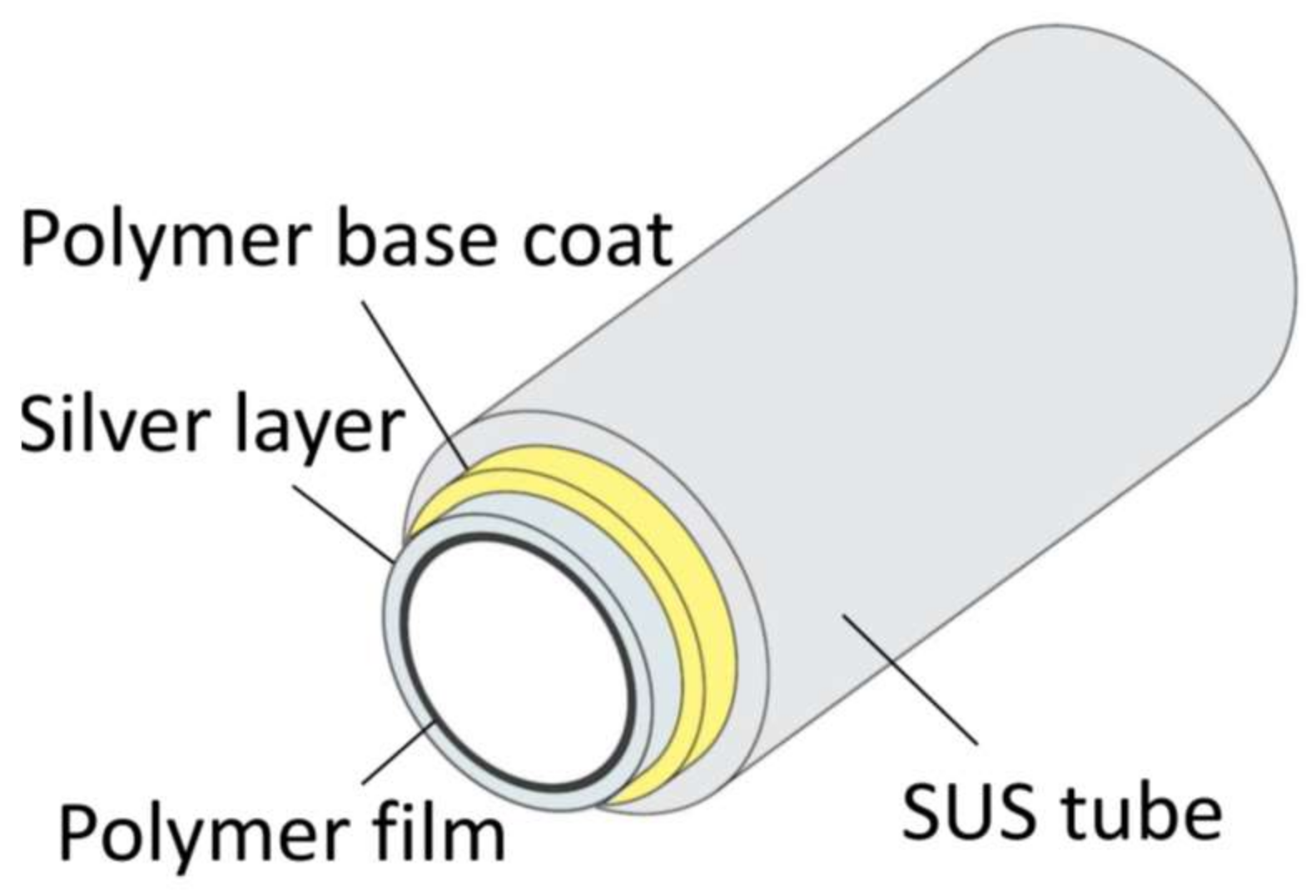
Figure 2.
Surface roughness of inner surface of SUS tubing as a function of number of coats of the acrylic resin.
Figure 2.
Surface roughness of inner surface of SUS tubing as a function of number of coats of the acrylic resin.

Figure 3.
Inner surface of SUS tubing observed by atomic force microscopy (AFM) after applying two and four layers of base coating. The RMS roughness are 119 nm for two coats and 83 nm for four coats. (a) two times re-coating; (b) four times re-coating.
Figure 3.
Inner surface of SUS tubing observed by atomic force microscopy (AFM) after applying two and four layers of base coating. The RMS roughness are 119 nm for two coats and 83 nm for four coats. (a) two times re-coating; (b) four times re-coating.

Figure 4.
Loss spectra of cyclic olefin polymer (COP)-coated hollow fibers in the visible to near-infrared region before and after removal and re-coating of the COP film.
Figure 4.
Loss spectra of cyclic olefin polymer (COP)-coated hollow fibers in the visible to near-infrared region before and after removal and re-coating of the COP film.
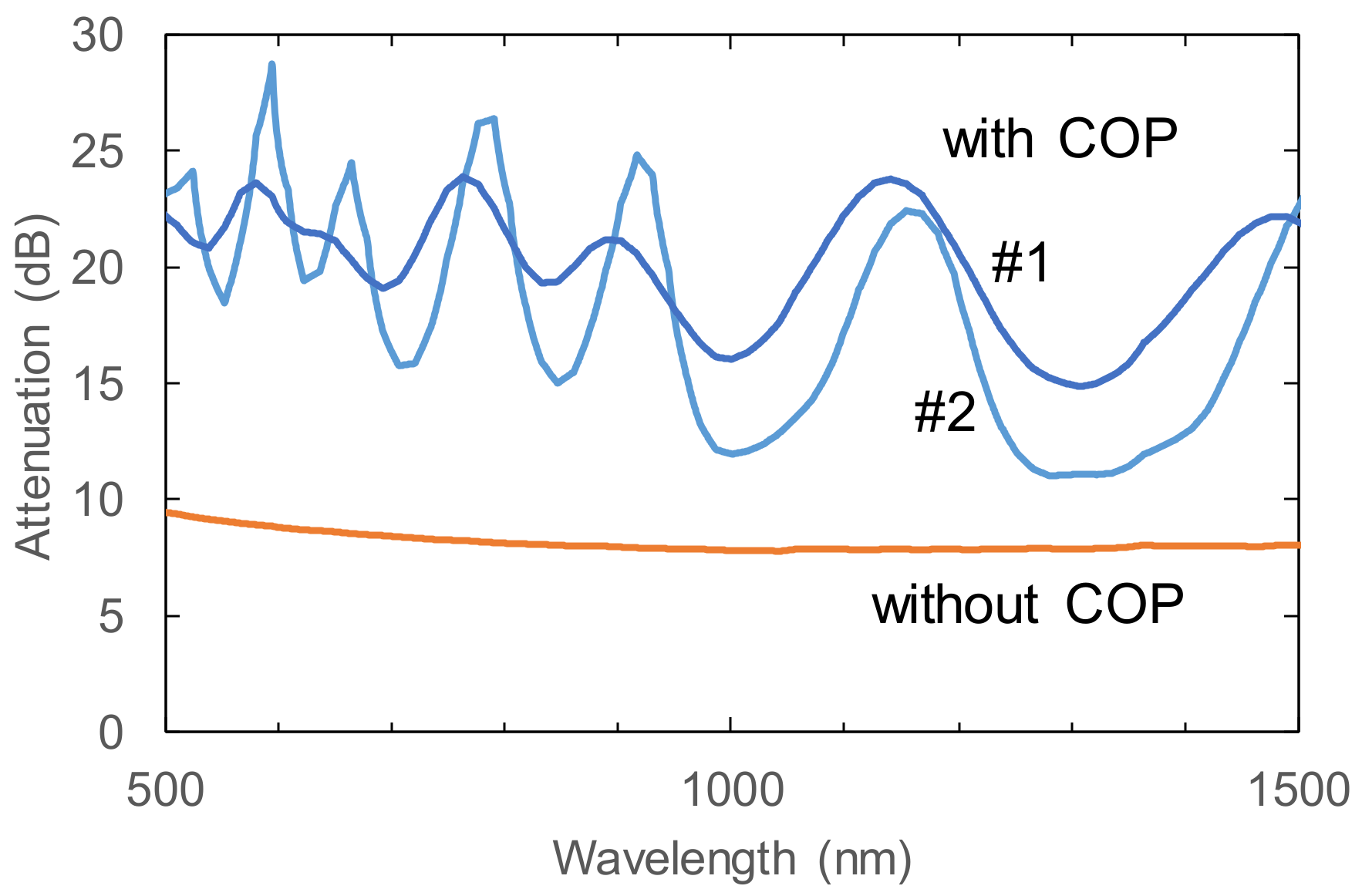
Figure 5.
Loss spectra of the COP-coated SUS fibers in (a) visible region and (b) mid-infrared region.
Figure 5.
Loss spectra of the COP-coated SUS fibers in (a) visible region and (b) mid-infrared region.

Figure 6.
Bending losses of the SUS COP-coated fibers measured with (a) 10.6-μm CO2 laser and (b) 532-nm laser. The inner diameter of the fiber is 550 μm and the length is 1 m.
Figure 6.
Bending losses of the SUS COP-coated fibers measured with (a) 10.6-μm CO2 laser and (b) 532-nm laser. The inner diameter of the fiber is 550 μm and the length is 1 m.

Table 1.
Measured losses of SUS-based and glass-based hollow optical fibers.
| Fiber Type | Straight Loss (dB/m) | Additonal Loss by 90-Deg Bending (dB) | |||
|---|---|---|---|---|---|
| λ = 532 nm | 10.6 μm | 532 nm | 10.6 μm | ||
| SUS based | With COP | 10.6 | 0.75 | 5.9 | 1.0 |
| Without COP | 8.4 | 4.3 | 5.0 | 8.9 | |
| Glass based | With COP | 9.4 | 0.8 | 1.5 | 1.2 |
© 2018 by the authors. Licensee MDPI, Basel, Switzerland. This article is an open access article distributed under the terms and conditions of the Creative Commons Attribution (CC BY) license (http://creativecommons.org/licenses/by/4.0/).
Share and Cite
MDPI and ACS Style
Iwai, K.; Takaku, H.; Miyagi, M.; Shi, Y.-W.; Matsuura, Y. Fabrication of Shatter-Proof Metal Hollow-Core Optical Fibers for Endoscopic Mid-Infrared Laser Applications. Fibers 2018, 6, 24. https://doi.org/10.3390/fib6020024
AMA Style
Iwai K, Takaku H, Miyagi M, Shi Y-W, Matsuura Y. Fabrication of Shatter-Proof Metal Hollow-Core Optical Fibers for Endoscopic Mid-Infrared Laser Applications. Fibers. 2018; 6(2):24. https://doi.org/10.3390/fib6020024
Chicago/Turabian StyleIwai, Katsumasa, Hiroyuki Takaku, Mitsunobu Miyagi, Yi-Wei Shi, and Yuji Matsuura. 2018. "Fabrication of Shatter-Proof Metal Hollow-Core Optical Fibers for Endoscopic Mid-Infrared Laser Applications" Fibers 6, no. 2: 24. https://doi.org/10.3390/fib6020024
Note that from the first issue of 2016, this journal uses article numbers instead of page numbers. See further details here.