Modelling and Design of Lanthanide Ion-Doped Chalcogenide Fiber Lasers: Progress towards the Practical Realization of the First MIR Chalcogenide Fiber Laser


1
Telecommunications and Teleinformatics Department, Wroclaw University of Science and Technology, 50-370 Wroclaw, Poland
2
George Green Institute, The University of Nottingham, Nottingham NG7 2RD, UK
Fibers 2018, 6(2), 25; https://doi.org/10.3390/fib6020025
Submission received: 9 February 2018
/
Revised: 2 March 2018
/
Accepted: 12 April 2018
/
Published: 20 April 2018
Abstract
:This paper presents the progress in the fields of the modelling and design of lanthanide ion-doped chalcogenide glass fiber lasers. It presents laser cavity designs that have been developed in order to optimize the performance of lanthanide ion-doped chalcogenide glass fiber lasers. Additionally, various numerical algorithms that have been applied for the optimization of chalcogenide glass lasers are reviewed and compared. The comparison shows that a combination of less accurate but more robust algorithms with more accurate ones gives the most promising performance.
1. Introduction
Mid-infrared (MIR) light sources covering the spectral range from 3 μm to 25 μm have many potential applications in the fields of biology, medicine, monitoring, agriculture and security. This is because many molecular bonds have resonant oscillation frequencies that are within the MIR wavelength range.
The key enabling technology for exploiting the potential benefits of MIR light is the availability of a low-cost, robust light source. There are several kinds of light sources currently available that cover the MIR wavelength range [1]. Wide-band light sources include synchrotron, Globar, light emitting diodes (LEDs) and supercontinuum (SC) sources. Synchrotron facilities are available only in few countries in the world. Such facilities are extremely expensive to develop and maintain. Globar, on the other hand, provides a relatively large total output power at a relatively low cost. However, the spectral power density is low; the filament operates at a very high temperature, but only a small part of the emitted power can be effectively collected by external optics and used in applications. LEDs, on the other hand, have very low output power and cover only a small fraction of the entire MIR spectrum. Finally, supercontinuum sources provide a wide wavelength band. Recently, SC sources covering wavelengths up to 13 μm were demonstrated [2]. However, MIR SC sources require a short-pulse, high-power seed pump, which is usually realized using either optical parametric oscillators (OPOs) or fiber-pulsed lasers. This makes MIR SC sources pricey and limits their robustness. Additionally, the fact that the SC is seeded by a train of pulses limits the range of possible applications. There are also narrowband sources that cover the MIR wavelength range. These include CO and CO2 lasers, Difference Frequency Generation (DFG), optical parametric oscillators (OPOs) and quantum cascade lasers (QCLs). These sources cover only selected wavelengths. However, some of them can be used to measure wide-band MIR spectra by tuning the operating wavelength. This applies, in particular, to OPOs and QCLs. However, both OPOs and tunable QCLs are very expensive. Fiber lasers have also been demonstrated for the MIR wavelength range. Fiber lasers have many characteristics that make them desirable for a number of specific applications. With fiber lasers, it is relatively easy to obtain a single transverse mode operation. Further, fiber lasers greatly facilitate beam delivery. The wide gain of lanthanide ion-doped fiber lasers makes them desirable when wavelength tuneability is needed. Also, wide gain spectra are useful for the generation of ultrashort pulses within the modelocked regime. The fiber lasers practically realized for the MIR wavelength range so far use ZBLAN fibers doped with erbium, holmium or dysprosium. Using this technology, the longest operating wavelength achieved so far is 3.9 μm [3], when cooling with liquid nitrogen and 3.68 μm [4] in room temperature. Unfortunately, the realization of ZBLAN fiber lasers operating at a wavelength longer than 4 μm has been impeded by the depopulation of higher energetic states via multiphonon transitions. Hence, for the realization of fiber lasers with longer operating wavelengths, novel host glasses are needed that have lower phonon energy than ZBLAN glasses. Currently, one of the most researched candidates for the realization of this task is chalcogenide glass.
Chalcogenide glass fibers doped with lanthanide ions have been developed for at least two decades now and show consistently good photoluminescence properties within the MIR wavelength range up to 5.5 μm [5,6,7,8,9,10,11,12,13]. The observed photoluminescence lifetimes are near to the radiative lifetimes predicted by the Judd-Ofelt theory. The fiber attenuation has been driven down to the dB/km level [14,15]. Lanthanide ion concentrations of up to 2000 ppm without crystallization have been achieved [6].
Significant progress has also been achieved in developing the technological basis for MIR photonics using chalcogenide glass fiber in a similar way as was achieved for the visible and near infrared wavelength range. So far, successful splicing with silica fiber has been demonstrated [16]. Chalcogenide glass fiber devices have been demonstrated that allow for beam combining of QCLs [17] and imaging for MIR [18]. Optical attenuators have been demonstrated [19]. Raman lasers have been successfully demonstrated [20]. Additionally, novel technology has been developed to reduce the fiber end facet reflection using direct stamping for nanoimprinting moth-eye structures [21]. Several sensors have been successfully realized using MIR light and chalcogenide glass technology [22,23,24]. All these achievements show the enormous potential of chalcogenide glass fiber technology, which will hopefully one day lead to the successful realization of lanthanide ion-doped chalcogenide glass fiber-based lasers with operating wavelengths beyond 4 μm.
This paper provides a review of the progress that has been made so far towards the realization of the first practically working lanthanide ion fiber laser using chalcogenide glass technology in the scientific fields of modelling and design. In the first section, a review of the chalcogenide glass fiber technology is given. In the second section, laser cavity designs are discussed that have so far been proposed in the available literature for the realization of chalcogenide glass fiber lasers. In the third section, the details of the modelling methods that have been applied to the design of the chalcogenide glass fiber lasers and to the prediction of their performance are presented. In the last section, a summary of the presented review is provided, and a discussion of the prospects of the successful realization of the first lanthanide ion-doped chalcogenide glass MIR fiber laser is given.
2. MIR Fiber Laser Cavity Design
A number of lanthanide ions have been studied in the context of fiber lasers operating within the MIR wavelength range. A suitable review can be found in [25]. In the context of the chalcogenide glass fiber lasers, the ions that have received the most attention are: praseodymium, dysprosium and terbium [13,26]. Praseodymium doped into a chalcogenide selenide glass can be pumped using 1480 nm laser diodes, which is of particular advantage since these laser diodes are commercially available at a relatively low cost when compared with the output power. The reason for this is the fact that 1480 nm laser diodes are applied to pump the erbium doped fiber amplifiers used in optical telecoms. The other pumping wavelengths available for praseodymium are 1550 nm, 2000 nm and the resonant pumping at approximately 4500 nm (Figure 1). For all these wavelengths, laser diodes are available. 2000 nm is also suitable for the application of thulium-doped fiber lasers. It is also worth noting that, at 4500 nm, the QCL lasers have the largest available output power, which is an additional advantage. There are energetic levels that allow pumping of praseodymium at shorter wavelengths. However, chalcogenide selenide glass absorption makes pumping at these wavelengths inefficient. In terms of the MIR output wavelengths, praseodymium has two bands that show in the photoluminescence. One of them is around 3700 nm, while the other is around 4900 nm, with the longest photoluminescence wavelength observed at approximately 5500 nm.
The pumping wavelengths available for dysprosium are approximately 1100 nm, 1300 nm, 1700 nm and 2900 nm (Figure 2). Laser diodes with wavelengths corresponding approximately to the first 3 wavelengths are commercially available. 2900 nm can be obtained from either erbium- or dysprosium-doped ZBLAN fiber laser, which slightly complicates potential laser realization. In terms of the MIR output spectrum, again, two bands are experimentally observed in chalcogenide selenide glass: one at around 3200 nm and the other one at around 4600 nm, with the longest wavelength observed when doped into the chalcogenide selenide glass at approximately 5000 nm. Again, similarly to the case of praseodymium, there are energetic levels that allow pumping of dysprosium at shorter wavelengths, but chalcogenide selenide glass absorption makes pumping at these wavelengths inefficient.
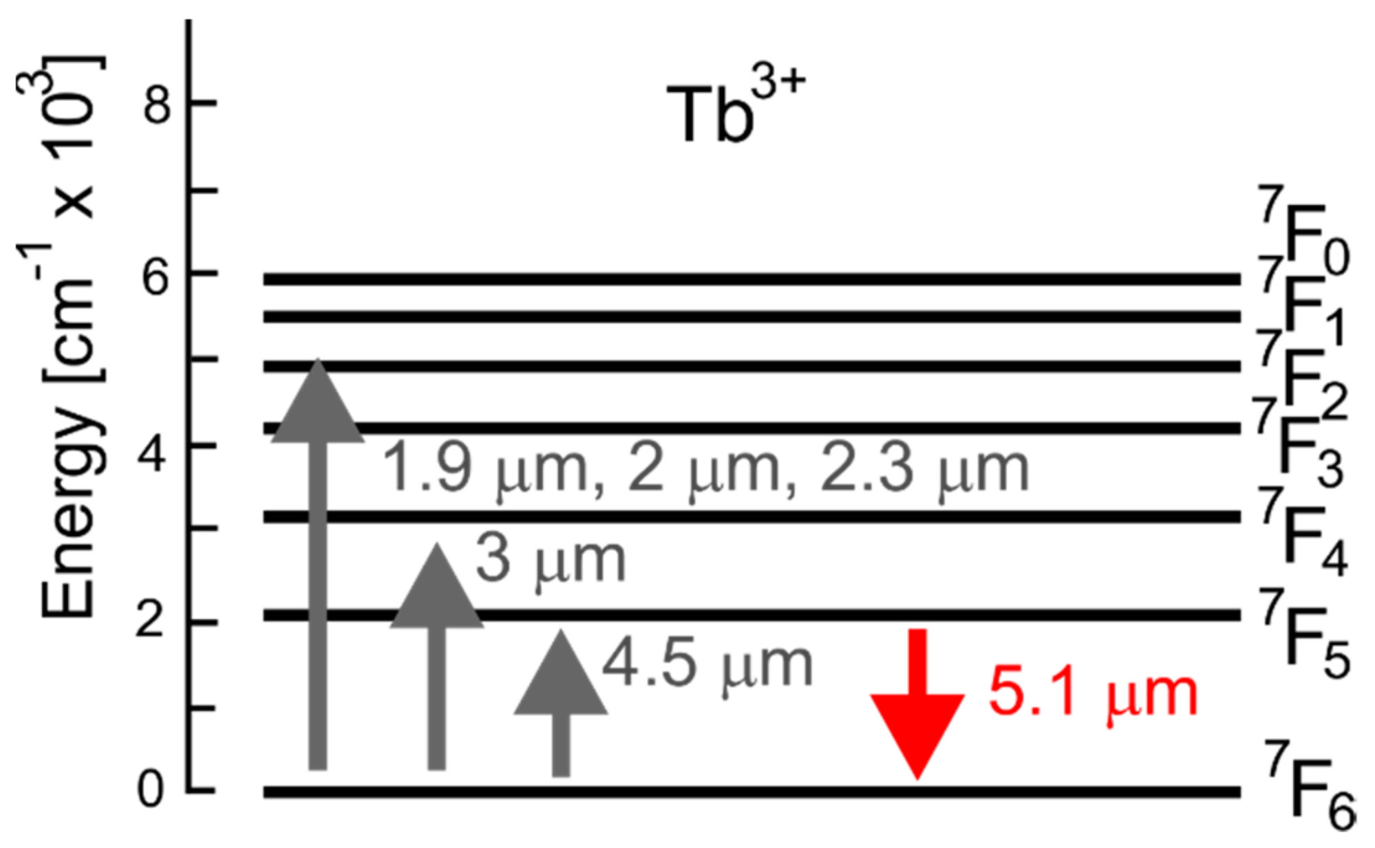
For terbium, the available pumping wavelengths are approximately 1900 nm, 2000 nm, 2300 nm, 3000 nm and 4500 nm (Figure 3). When compared with dysprosium and praseodymium, the commercial availability of laser diodes for pumping terbium is limited. Again, 4500 nm is accessed well by high-power QCL lasers. 2000 nm is well suited for the application of the thulium fiber lasers. 3000 nm is well suited for holmium doped ZBLAN fiber lasers. There are also laser diodes available for 1900 nm, 2000 nm and 2300 nm, but the range of available output powers is limited. For terbium, there are no other energetic levels available for pumping in the fundamental configuration. There is also one MIR output band available when doping a chalcogenide selenide glass, which is centered around 5100 nm and stretches up to approximately 5500 nm.
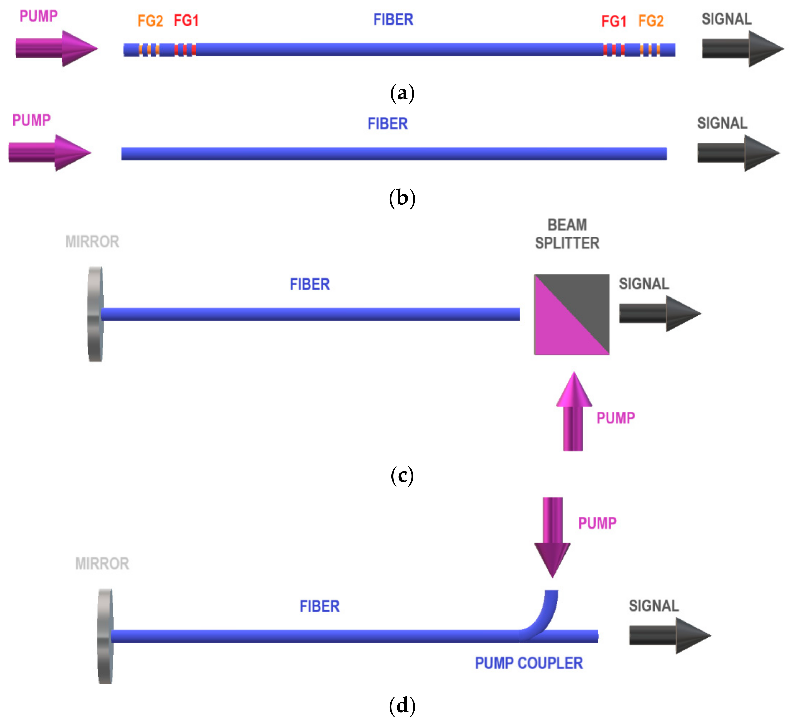
The first cavity proposed in the literature for a realization of an efficient chalcogenide glass fiber laser was based on dysprosium ions and used the concept of cascade lasing [27]. The schematic diagram of this cavity is shown in Figure 4a. Fiber Grating 1 (FG1) is inscribed in order to trap the idler at around 3100 nm, while FG2 forms the cavity for the output signal, which operates at approximately 4500 nm. The role of the idler is to deplete the lower lasing level 6H13/2 by effectively transferring the ions into the 6H15/2 level. The signal interacts with the levels 6H11/2 and 6H13/2.
If the idler wave is not present within the cavity (Figure 4a) then a saturation of the output signal is observed at a level of several mW. Figure 5 shows a typical dependence of the MIR output signal power on the pump power for a dysprosium doped chalcogenide glass fiber laser operating within the cascade scheme with idler interacting with levels 6H13/2 and 6H15/2 while the signal interacts with 6H11/2 and 6H13/2 when pumped using approximately 1700 nm. Two regions are distinguishable within the range of the pump powers. In the first region, the idler power is approximately equal to zero, while the signal power initially grows linearly and then saturates. The saturation is due to the long lifetime of the level 6H13/2. In region 2, the idler starts lasing action between the fiber gratings and also begins to deplete the level 6H13/2. Thus, the idler facilitates the achievement of the population inversion for the signal. In the dependence of the signal power on the pump power this is shown as a restoration of the linear growth of the signal power.
The disadvantage of the laser cavity design shown in Figure 4a is that its realization is predicated upon a successful fabrication of two pairs of fiber gratings, which is a technological challenge. In [28], therefore, some alternative solutions were proposed, which would be simpler for practical implementation. The design shown in Figure 4b consists of a fiber stretch only. This cavity design relies on the large refractive index of chalcogenide glass. As a result, a large value of Fresnel reflection from the fiber end facet can be expected. The experimental data suggest that approximately 20% of Fresnel reflection is achievable. The results obtained show that the efficiency of the cavity design from Figure 4b is much lower than that of Figure 4a. The efficiency can, however, be improved by terminating one end of the fiber with a mirror and using a beam splitter at the other end to separate the pump wave from the signal wave (Figure 4c). Alternatively, a pump coupler could be used to make an all fiber structure (Figure 4d). Both the designs from Figure 4c,d have similar efficiency to the design from Figure 4a [28]. Hence, they both present viable alternatives to the necessity of fabricating two pairs of fiber gratings.
The cascade lasing scheme was further explored in [26] to study comparatively the dependence of the output power on the pump power for dysprosium, praseodymium and terbium ion doping. The terbium ion-doped laser was pumped at 2950 nm, while the praseodymium ion-doped one was pumped at 2040 nm. This study showed that the best lasing efficiency could be obtained from a praseodymium ion-doped chalcogenide glass fiber laser. This can mainly be attributed to the large value of the pump absorption cross section at around 2000 nm when compared with the other two ions. The maximum efficiency obtained in this study did not exceed 20%.
More recent studies have concentrated on the improvement of the lasing efficiency, while finding alternatives to the cascade pumping scheme [29,30,31,32]. In [31], use of dual pump was proposed to bring the lasing efficiency above 20%. Dysprosium ion doping was applied, and pumps with wavelengths of 2850 nm and 4092 nm were used. A photonic crystal fiber was proposed to enforce single-mode operation and pump and signal wavelengths. A practical realization of a laser cavity with two pump lasers may prove challenging; therefore, an alternative solution was presented in [32], which makes it possible to improve the laser efficiency with much less challenge with respect to practical realization. By combining a master oscillator with a power amplifier (Figure 6) and using 1700 nm pump only, a slope efficiency as high as 38% can be achieved. The main role of a pump amplifier is to utilize the unused pump power from the master oscillator stage.
The most recent design that has been proposed is shown in Figure 7. It relies on terbium ion doping and on the fact that terbium ion, when doped into chalcogenide selenide glass and pumped at 2950 nm, forms a classical 3-level lasing system. This results in a very simple structure of the laser (Figure 7). Due to multiphonon depopulation, other pumping wavelengths than the ones using the level 7F4 can also be applied, but at the cost of reduced efficiency. The results shown in [10] predict a slope efficiency of more than 40%, despite the very simple cavity design.
In the next section, the numerical models used for the design of chalcogenide glass fiber lasers are discussed.
3. Numerical Modelling Methods
In the literature concerning lanthanide ion-doped chalcogenide glass fiber modelling and design, steady state analysis is dominant. This relies on solving the rate equations for the relevant levels with a set of ordinary differential equations that describe the distribution of the pump and signal powers within the cavity. The equations are solved consistently for given boundary conditions that are imposed at the cavity end facets. In order to discuss in more detail the numerical methods used in analysis of chalcogenide glass fiber lasers, we focus our discussion on a dysprosium-doped chalcogenide glass fiber laser that operates within the cascade lasing scheme pumped at 1710 nm, as discussed in Section 2 (Figure 4 and Figure 8) [28]. The algorithms used in this case are identical to those used for the analysis of standard fiber laser cavities, and hence the discussed models can be readily applied to the design and analysis of other laser cavities discussed in Section 2. For dysprosium ion doped into a chalcogenide selenide glass the rate equations can have a matrix form:
where N is the total dysprosium concentration, and the matrix elements are:
The indices used in Equations (1) and (2) are easier to follow if one associates levels 1, 2 and 3 with levels 6H15/2, 6H13/2 and 6H11/2 from Figure 2, respectively. In Equations (1) and (2) τ3 and τ2 are the lifetimes of levels 6H11/2 and 6H13/2, respectively, β32 is the branching ratio for the 6H11/2 → 6H13/2 transition and σxya/e denotes the absorption/emission cross-section for the transition xy. Symbols , (λ1) and (λ2) denote the photon flux for the pump, signal and idler, respectively. The photon flux is related to optical powers P by the following expressions: = Pp λp/(A h c), (λ1) = P(λ1) λ1/(A h c) and (λ2) = P(λ2) λ2/(A h c). A denotes the doping cross-section, h is Planck’s constant, while c is the speed of light in free space and the confinement factor is denoted as .
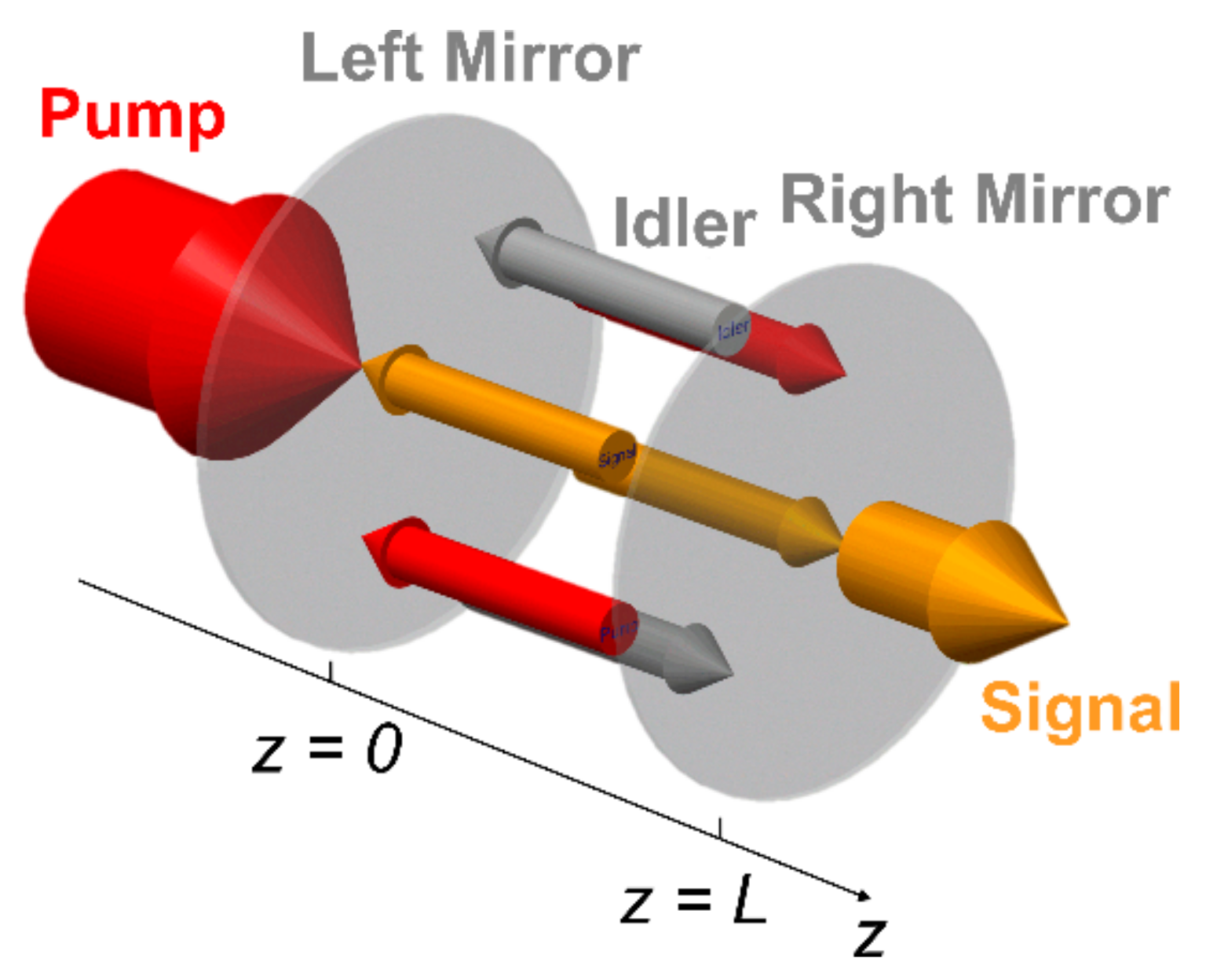
The pump, idler and signal waves are trapped between the cavity mirrors and interact with the dopant ions (Figure 8). If the fiber is aligned with the z axis of a rectangular coordinate system the equations that describe the spatial distribution of the pump, signal and idler wave power are given by the following set of 6 ordinary differential equations:
where ‘+’ and ‘−’ indexes refer to forward and backward propagating waves, respectively. The total power needed for evaluating Equations (1) and (2) is obtained by adding the longitudinal power distributions for the forward and backward propagating waves. The boundary conditions for Equations (1)–(5) and the cavity shown in Figure 8 are given by:
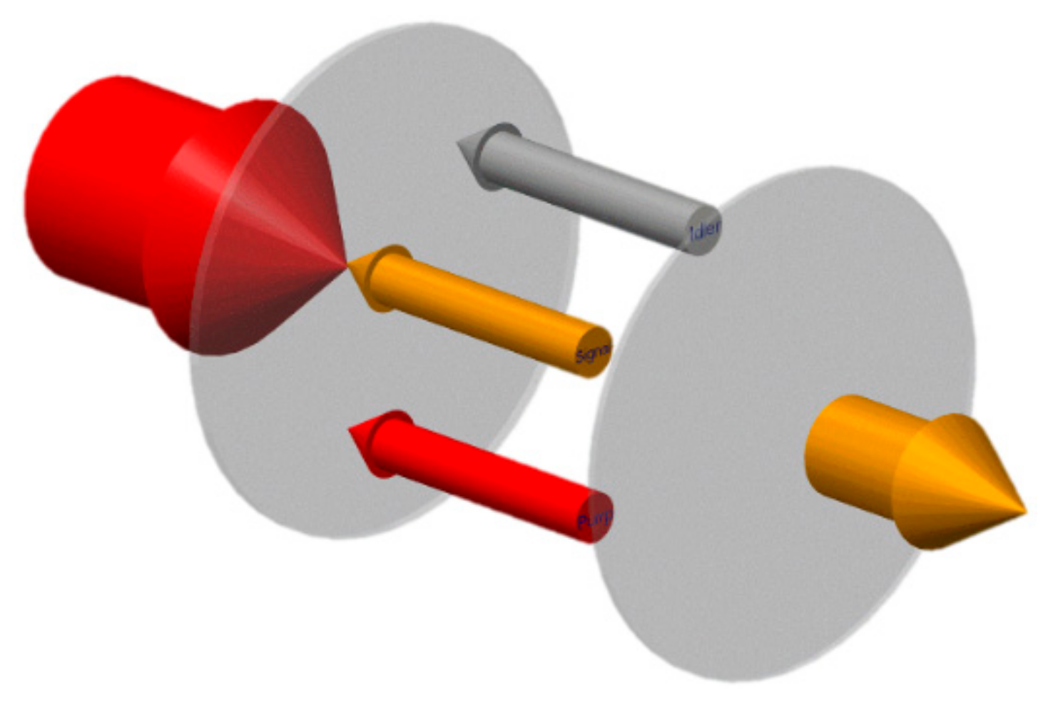
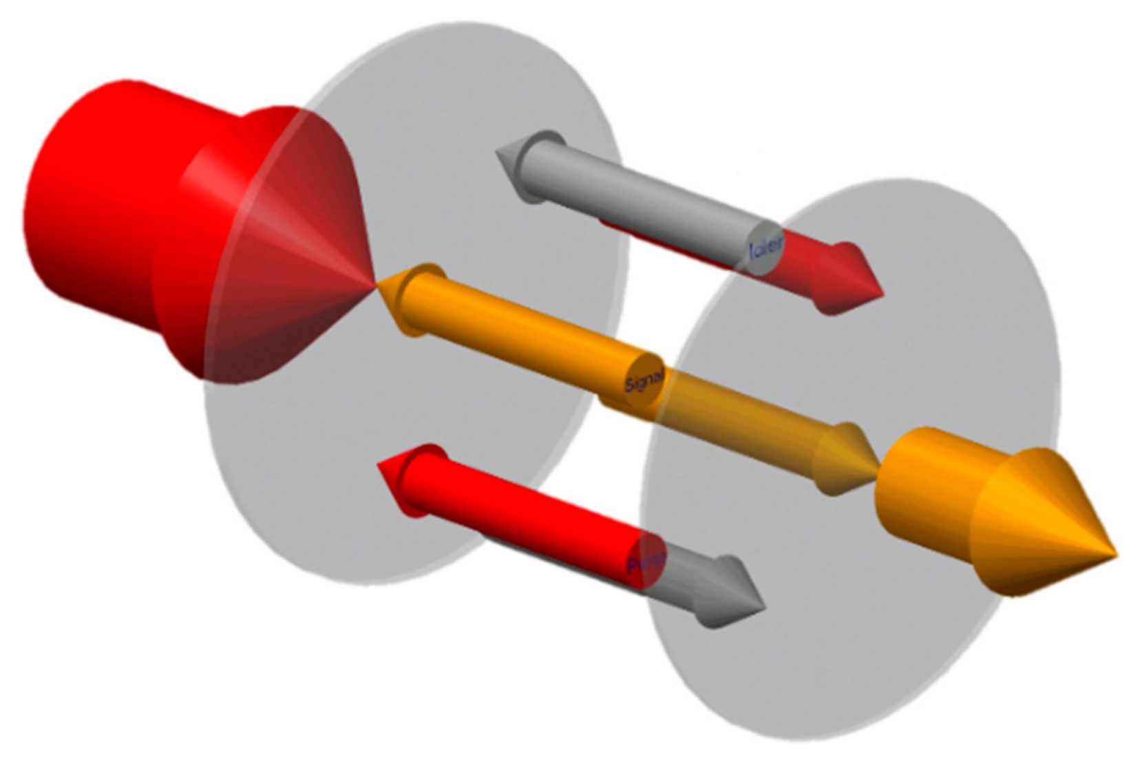
Several techniques have been proposed in the literature for the solution of the Equations (1)–(6) [33]. One of them is referred to as the coupled solution method (CSM) and has been adapted from the field of high-power laser analysis [34,35]. CSM solves Equations (3)–(5) by setting non-zero guess values to powers of forward propagating waves at z = 0, whilst zeroing the backward propagating wave powers. In the next step, the Equations (3)–(5) are integrated for forward propagating waves only from z = 0 to z = L, using a standard algorithm to solve a set of ordinary differential equations, e.g., the Runge-Kutta method, thus solving a standard initial value problem (Figure 8 and Figure 9). At the right mirror, the boundary conditions (6) are applied, and the values of backward propagating wave powers at z = L are calculated from the values of forward propagating wave powers at z = L. These values are then used as initial values for integration of the Equations (3)–(5) for backward propagating waves from z = L to z = 0 (Figure 8 and Figure 10). At the left mirror, the boundary conditions (6) are applied, and the values of forward propagating wave powers at z = 0 are calculated from the values of backward propagating wave powers at z = 0. This gives a new update of the forward propagating waves powers at z = 0. These values can be used to calculate a residual based on a difference between the newly updated values and those initially guessed. If the residual is larger than the predefined threshold another iteration of the method is carried out by integrating forward waves to the right mirror, applying boundary condition, propagating the backward waves to the left mirror and applying the boundary conditions. After completing another round trip, the residual check may be performed again. The iterations of CSM are continued until the prescribed residual is reached. A method that is, in principle, similar to CSM is a relaxation method (RM).
In RM, the algorithm is initiated by setting non-zero guess values to powers of all waves at z = 0. One can use the boundary conditions (6) to do so consistently. In the next step, the Equations (3)–(5) are integrated for all waves from z = 0 to z = L (Figure 8 and Figure 11). At the right mirror, the boundary conditions (6) are applied, and the values of backward propagating wave powers at z = L are calculated from the values of forward propagating wave powers at z = L. These values are then used as initial values for integration of the Equations (3)–(5) for all waves from z = L to z = 0 (Figure 8 and Figure 11). At the left mirror, the boundary conditions (6) are applied, and the values of forward propagating wave powers at z = 0 are calculated from the values of backward propagating waves powers at z = 0. This gives a new update of the forward propagating waves powers at z = 0 and the possibility of calculating a residual. Again, the RM iterations are continued until the prescribed residual is reached.
The third method that has been used for the analysis of chalcogenide glass fiber lasers is the Shooting Method combined with Newton-Raphson Method (SM-NRM). SM-NRM relies on the observation that the integration of Equations (3)–(5) from z = 0 to z = L sets an implicit functional relationship between the values of the powers at z = 0 with those at z = L. In order to obtain a set of implicitly formulated nonlinear algebraic equations, one only needs to apply boundary conditions (6). This yields a set of implicitly formulated nonlinear algebraic equations, whereby the unknowns are the power values for all waves at z = 0. The value of the nonlinear functions is calculated by integrating all powers from z = 0 to z = L according to (3)–(5) and applying (6) at z = L. Since the nonlinear functions are not given explicitly, the Jacobian matrix elements have to be calculated using the finite difference method. Similarly, as in the case of CSM and RM the subsequent iterations of Newton-Raphson method are continued until the desired value of the residual is reached.
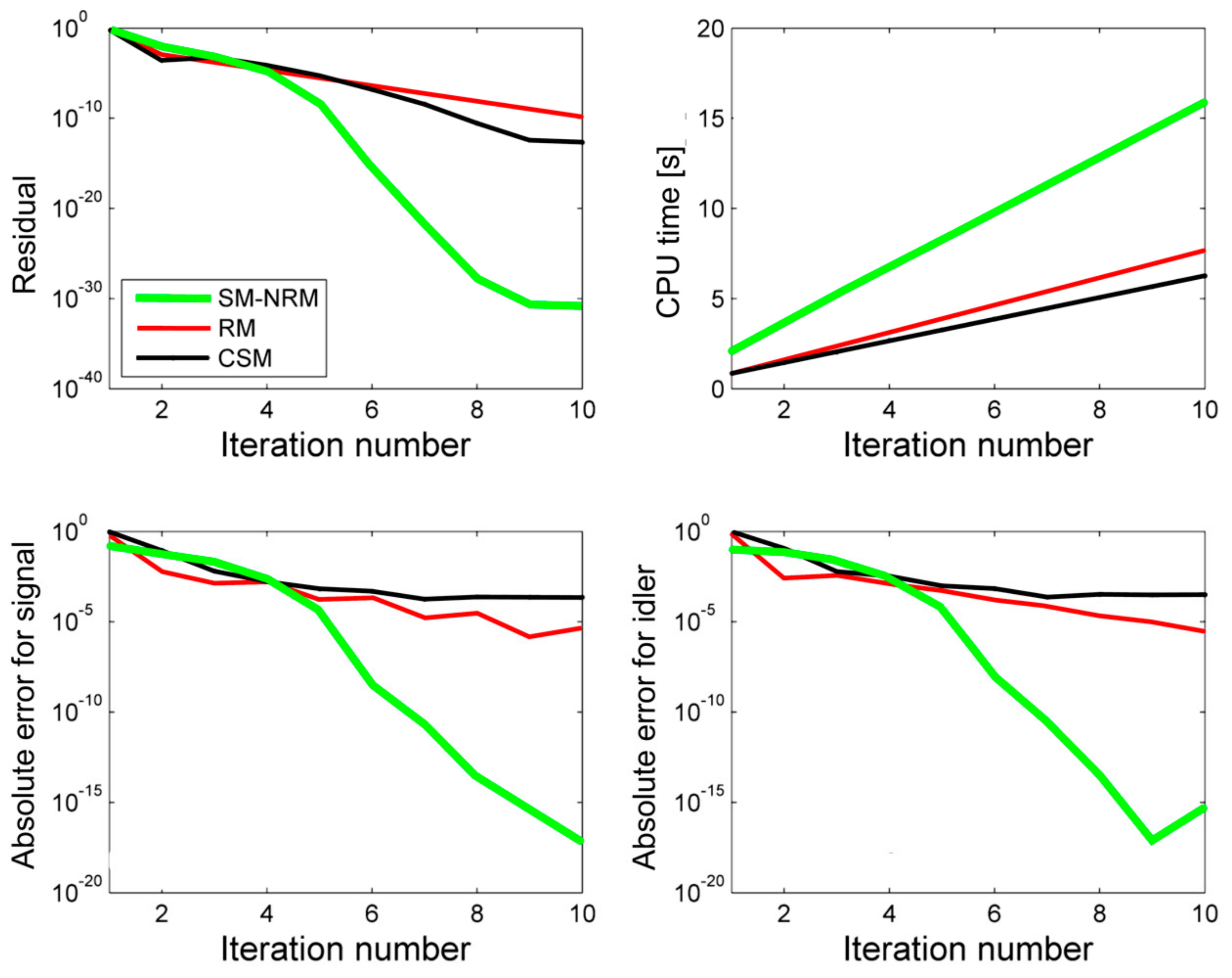
Figure 12 shows results of a comparative study for all three methods. The CSM and RM have similar properties. They show a good initial convergence both for the signal and the idler. However, after several initial iterations, the SM-NRM converges much faster than CSM and RM. We note that in the case of the idler wave, a fast convergence rate of SM-NRM results in approaching, after 9 iterations, the numerical noise floor for double precision arithmetic, which was used in simulations, and hence an apparent growth of the absolute error in the iteration 10 is observed. The comparison of the CPU time shows that SM-NRM is more costly per iteration step than CSM and RM. Further, study also reveals that CSM and RM are less sensitive than SM-NRM to the quality of the initial guess. Hence, an optimal strategy is to combine either CSM or RM with SM-NRM. In such an algorithm, either CSM or RM is used to perform several initial iterations and the algorithm is switched to SM-NRM. The main characteristics of SM-NRM, RM and CSM are summarized in Table 1.
4. Summary
A review of cavity designs and numerical modelling techniques for lanthanide ion-doped chalcogenide glass fiber lasers was presented. The comparative study of several algorithms shows that the best numerical efficiency is achieved by combining the Shooting Method—Newton-Raphson Method with either the Relaxation Method or the Coupled Solution Method. The currently available cavity designs predict the slope efficiency in the range of between 30% and 40% for chalcogenide fibers with experimentally demonstrated doping levels. According to the results obtained, output powers in the range of several hundreds of mW should be realizable. However, the experimental efforts so far have not been successful. Among the possible reasons for the lack of success might be the intrinsic fiber loss, which might be higher at the laser operating wavelength than what one could expect estimating the fiber loss at an adjacent wavelength. This is due to presence of impurities, like SeH. Further, the thermal properties of the fibers and their ability to handle high power density is still a subject of intensive research. It is possible that the further improvement of fiber fabrication technology with an increased knowledge of thermal and optical properties will lead, in near future, to the realization of the first lanthanide ion-doped chalcogenide glass MIR fiber laser.
Acknowledgments
The author acknowledges support from the European Union’s Horizon 2020 research and innovation programme under the Marie Skłodowska-Curie grant agreement No. 665778 (National Science Centre, Poland, Polonez Fellowship 2016/21/P/ST7/03666).
Conflicts of Interest
The author declares no conflict of interests.
References
- Ebrahim-Zadeh, M.; Sorokina, I.T. (Eds.) Mid-Infrared Coherent Sources and Applications; Springer Verlag: New York, NY, USA, 2008. [Google Scholar]
- Petersen, C.R.; Moller, U.; Kubat, I.; Zhou, B.; Dupont, S.; Ramsay, J.; Benson, T.; Sujecki, S.; Abdel-Moneim, N.; Tang, Z.; et al. Mid-infrared supercontinuum covering the 1.4–13.3 mm molecular fingerprint region using ultra-high na chalcogenide step-index fibre. Nat. Photonics 2014, 8, 830–834. [Google Scholar] [CrossRef]
- Schneider, J.; Carbonnier, C.; Unrau, U.B. Characterization of a Ho3+-doped fluoride fiber laser with a 3.9-mm emission wavelength. Appl. Opt. 1997, 36, 8595–8600. [Google Scholar] [CrossRef] [PubMed]
- Qin, Z.P.; Xie, G.Q.; Ma, J.G.; Yuan, P.; Qian, L.J. Mid-infrared Er: Zblan fiber laser reaching 3.68 mm wavelength. Chin. Opt. Lett. 2017, 15, 111402. [Google Scholar]
- Churbanov, M.F.; Scripachev, I.V.; Shiryaev, V.S.; Plotnichenko, V.G.; Smetanin, S.V.; Kryukova, E.B.; Pyrkov, Y.N.; Galagan, B.I. Chalcogenide glasses doped with Tb, Dy and Pr ions. J. Cryst. Solids 2003, 326, 301–305. [Google Scholar] [CrossRef]
- Karaksina, E.V.; Shiryaev, V.S.; Churbanov, M.F.; Anashkina, E.A.; Kotereva, T.V.; Snopatin, G.E. Core-clad Pr(3+)-doped Ga(In)-Ge-As-Se-(I) glass fibers: Preparation, investigation, simulation of laser characteristics. Opt. Mater. 2017, 72, 654–660. [Google Scholar] [CrossRef]
- Sakr, H.; Furniss, D.; Tang, Z.; Sojka, L.; Moneim, N.A.; Barney, E.; Sujecki, S.; Benson, T.M.; Seddon, A.B. Superior photoluminescence (PL) of Pr3+-In, compared to Pr3+-Ga, selenide-chalcogenide bulk glasses and pl of optically-clad fiber. Opt. Expr. 2014, 22, 21236–21252. [Google Scholar] [CrossRef] [PubMed]
- Sakr, H.; Tang, Z.Q.; Furniss, D.; Sojka, L.; Sujecki, S.; Benson, T.M.; Seddon, A.B. Promising emission behavior in Pr3+/In selenide-chalcogenide-glass small-core step index fiber (SIF). Opt. Mater. 2017, 67, 98–107. [Google Scholar] [CrossRef]
- Sojka, L.; Tang, Z.; Furniss, D.; Sakr, H.; Beres-Pawlik, E.; Seddon, A.B.; Benson, T.M.; Sujecki, S. Numerical and experimental investigation of mid-infrared laser action in resonantly pumped Pr3+ doped chalcogenide fibre. Opt. Quantum Electron. 2017, 49, 1. [Google Scholar] [CrossRef]
- Sojka, L.; Tang, Z.; Furniss, D.; Sakr, H.; Fang, Y.; Beres-Pawlik, E.; Benson, T.M.; Seddon, A.B.; Sujecki, S. Mid-infrared emission in Tb3+-doped selenide glass fiber. J. Opt. Soc. Am. B Opt. Phys. 2017, 34, A70–A79. [Google Scholar] [CrossRef]
- Sojka, L.; Tang, Z.; Furniss, D.; Sakr, H.; Oladeji, A.; Beres-Pawlik, E.; Dantanarayana, H.; Faber, E.; Seddon, A.B.; Benson, T.M.; et al. Broadband, mid-infrared emission from Pr3+ doped GeAsGaSe chalcogenide fiber, optically clad. Opt. Mater. 2014, 36, 1076–1082. [Google Scholar] [CrossRef]
- Tang, Z.Q.; Furniss, D.; Fay, M.; Sakr, H.; Sojka, L.; Neate, N.; Weston, N.; Sujecki, S.; Benson, T.M.; Seddon, A.B. Mid-infrared photoluminescence in small-core fiber of praseodymium-ion doped selenide-based chalcogenide glass. Opt. Mater. Expr. 2015, 5, 870–886. [Google Scholar] [CrossRef]
- Shaw, L.B.; Cole, B.; Thielen, P.A.; Sanghera, J.S.; Aggarwal, I.D. Mid-wave IR and long-wave IR laser potential of rare-earth doped chalcogenide glass fiber. IEEE J. Quantum Electron. 2001, 37, 1127–1137. [Google Scholar] [CrossRef]
- Snopatin, G.E.; Shiryaev, V.S.; Plotnichenko, V.G.; Dianov, E.M.; Churbanov, M.F. High-purity chalcogenide glasses for fiber optics. Inorg. Mater. 2009, 45, 1439–1460. [Google Scholar] [CrossRef]
- Tang, Z.; Shiryaev, V.S.; Furniss, D.; Sojka, L.; Sujecki, S.; Benson, T.M.; Seddon, A.B.; Churbanov, M.F. Low loss Ge-As-Se chalcogenide glass fiber, fabricated using extruded preform, for mid-infrared photonics. Opt. Mater. Expr. 2015, 5, 1722–1737. [Google Scholar] [CrossRef]
- Thapa, R.; Gattass, R.R.; Nguyen, V.; Chin, G.; Gibson, D.; Kim, W.; Shaw, L.B.; Sanghera, J.S. Low-loss, robust fusion splicing of silica to chalcogenide fiber for integrated mid-infrared laser technology development. Opt. Lett. 2015, 40, 5074–5077. [Google Scholar] [CrossRef] [PubMed]
- Gattass, R.R.; Shaw, L.B.; Kung, F.H.; Gibson, D.J.; Nguyen, V.Q.; Chin, G.D.; Busse, L.E.; Aggarwal, I.D.; Sanghera, J.S. Infrared fiber N × 1 multimode combiner. IEEE Photonics J. 2013, 5. [Google Scholar] [CrossRef]
- Shaw, B.; Gibson, D.; Nguyen, V.; Gattass, R.R.; Sanghera, J.; Aggarwal, I. IR imaging bundles for hwil testing. In Technologies for Synthetic Environments: Hardware-in-the-Loop XVI; Mobley, S.B., Murrer, R.L., Eds.; International Society for Optics and Photonics: Orlando, FA, USA, 2011; Volume 8015. [Google Scholar]
- Gattass, R.R.; Shaw, L.B.; Sanghera, J.S. Broadband watt-level mid-infrared fiber-coupled variable optical attenuator. IEEE Photonics Technol. Lett. 2013, 25, 2007–2009. [Google Scholar] [CrossRef]
- Bernier, M.; Fortin, V.; El-Amraoui, M.; Messaddeq, Y.; Vallee, R. 3.77 mm fiber laser based on cascaded Raman gain in a chalcogenide glass fiber. Opt. Lett. 2014, 39, 2052–2055. [Google Scholar] [CrossRef] [PubMed]
- Weiblen, R.J.; Menyuk, C.R.; Busse, L.E.; Shaw, L.B.; Sanghera, J.S.; Aggarwal, I.D. Optimized moth-eye anti-reflective structures for As2S3 chalcogenide optical fibers. Opt. Expr. 2016, 24, 10172–10187. [Google Scholar] [CrossRef] [PubMed]
- Pele, A.L.; Braud, A.; Doualan, J.L.; Starecki, F.; Nazabal, V.; Chahal, R.; Boussard-Pledel, C.; Bureau, B.; Moncorge, R.; Camy, P. Dy3+ doped gegasbs fluorescent fiber at 4.4 µm for optical gas sensing: Comparison of simulation and experiment. Opt. Mater. 2016, 61, 37–44. [Google Scholar] [CrossRef]
- Starecki, F.; Charpentier, F.; Doualan, J.L.; Quetel, L.; Michel, K.; Chahal, R.; Troles, J.; Bureau, B.; Braud, A.; Camy, P.; et al. Mid-IR optical sensor for CO2 detection based on fluorescence absorbance of Dy3+:Ga5Ge20Sb10S65 fibers. Sens. Actuators B Chem. 2015, 207, 518–525. [Google Scholar] [CrossRef] [Green Version]
- Starecki, F.; Morais, S.; Chahal, R.; Boussard-Pledel, C.; Bureau, B.; Palencia, F.; Lecoutre, C.; Garrabos, Y.; Marre, S.; Nazabal, V. IR emitting Dy3+ doped chalcogenide fibers for in situ CO2 monitoring in high pressure microsystems. Int. J. Greenh. Gas Control 2016, 55, 36–41. [Google Scholar] [CrossRef]
- Digonnet, M.J.F. Rare-Earth-Doped Fiber Lasers and Amplifiers; CRC Press: New York, NY, USA, 2001. [Google Scholar]
- Sojka, L.; Tang, Z.; Zhu, H.; Beres-Pawlik, E.; Furniss, D.; Seddon, A.B.; Benson, T.M.; Sujecki, S. Study of mid-infrared laser action in chalcogenide rare earth doped glass with Dy3+, Pr3+ and Tb3+. Opt. Mater. Expr. 2012, 2, 1632–1640. [Google Scholar] [CrossRef]
- Quimby, R.S.; Shaw, L.B.; Sanghera, J.S.; Aggarwal, I.D. Modeling of cascade lasing in Dy : Chalcogenide glass fiber laser with efficient output at 4.5 µm. IEEE Photonics Technol. Lett. 2008, 20, 123–125. [Google Scholar] [CrossRef]
- Sujecki, S.; Sojka, L.; Beres-Pawlik, E.; Tang, Z.; Furniss, D.; Seddon, A.B.; Benson, T.M. Modelling of a simple Dy3+ doped chalcogenide glass fibre laser for mid-infrared light generation. Opt. Quantum Electron. 2010, 42, 69–79. [Google Scholar] [CrossRef]
- Falconi, M.C.; Laneve, D.; Prudenzano, F. Advances in Mid-IR fiber lasers: Tellurite, fluoride and chalcogenide. Fibers 2017, 5, 23. [Google Scholar] [CrossRef]
- Falconi, M.C.; Palma, G.; Starecki, F.; Nazabal, V.; Troles, J.; Adam, J.L.; Taccheo, S.; Ferrari, M.; Prudenzano, F. Recent advances on pumping schemes for Mid-IR PCF lasers. In Optical Components and Materials XIV; Jiang, S., Digonnet, M.J.F., Eds.; International Society for Optics and Photonics: San Francisco, CA, USA, 2017; Volume 10100. [Google Scholar]
- Falconi, M.C.; Palma, G.; Starecki, F.; Nazabal, V.; Troles, J.; Taccheo, S.; Ferrari, M.; Prudenzano, F. Design of an efficient pumping scheme for Mid-IR Dy3+:Ga5Ge20Sb10S65 PCF fiber laser. IEEE Photonics Technol. Lett. 2016, 28, 1984–1987. [Google Scholar] [CrossRef]
- Falconi, M.C.; Palma, G.; Starecki, F.; Nazabal, V.; Troles, J.; Adam, J.L.; Taccheo, S.; Ferrari, M.; Prudenzano, F. Dysprosium-doped chalcogenide master oscillator power amplifier (MOPA) for Mid-IR emission. J. Lightwave Technol. 2017, 35, 265–273. [Google Scholar] [CrossRef]
- Sujecki, S. An efficient algorithm for steady state analysis of fibre lasers operating under cascade pumping scheme. Int. J. Electron. Telecommun. 2014, 60, 143–149. [Google Scholar]
- Sujecki, S.; Borruel, L.; Wykes, J.; Moreno, P.; Sumpf, B.; Sewell, P.; Wenzel, H.; Benson, T.A.; Erbert, G.; Esquivias, I.; et al. Nonlinear properties of tapered laser cavities. IEEE J. Sel. Top. Quantum Electron. 2003, 9, 823–834. [Google Scholar] [CrossRef]
- Sujecki, S. Photonics Modelling and Design; CRC Press: Boca Raton, FL, USA, 2014. [Google Scholar]
Figure 1.
Energy level diagram for a praseodymium ion doped into selenide chalcogenide glass.
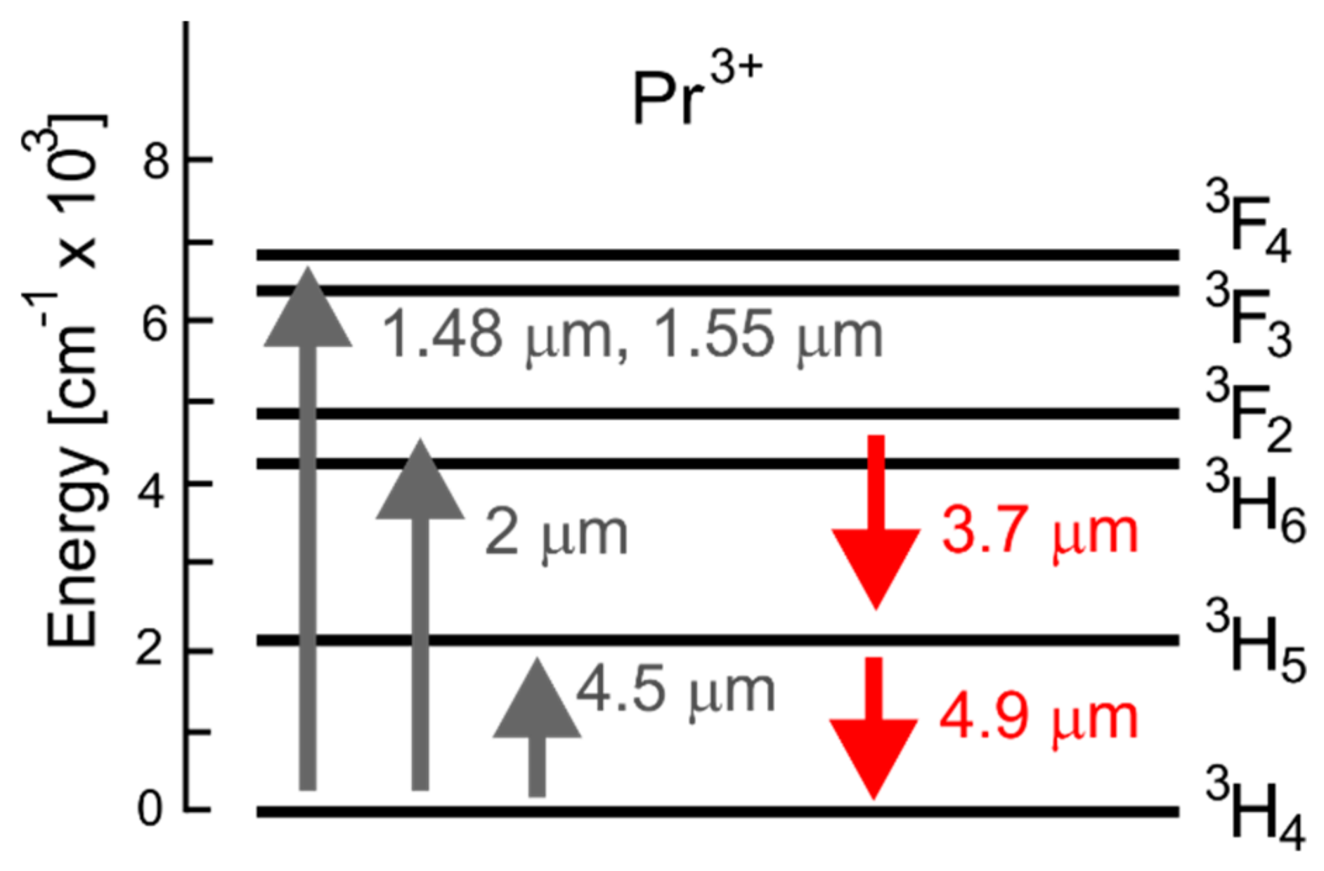
Figure 2.
Energy level diagram for a dysprosium ion doped into selenide chalcogenide glass.
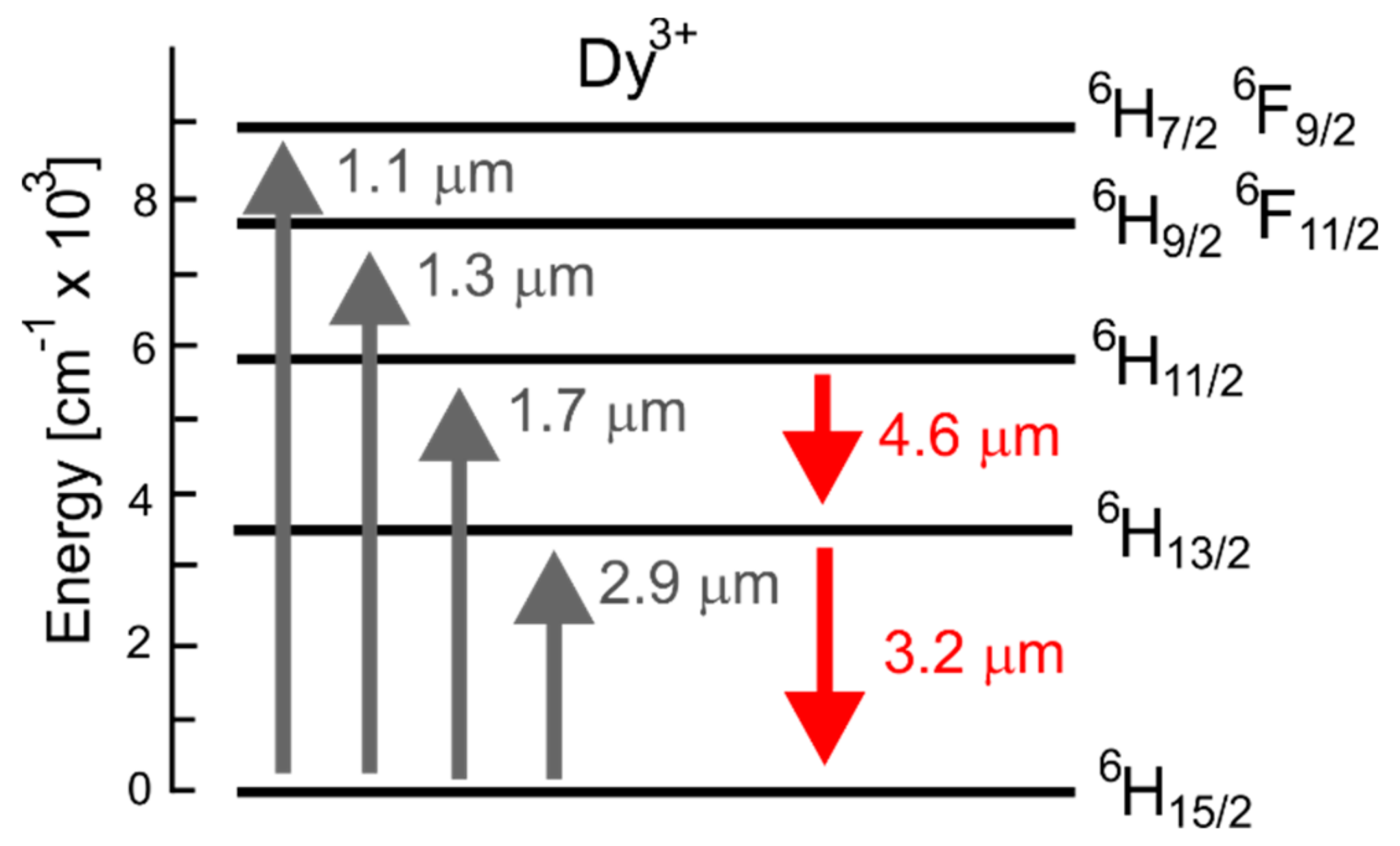
Figure 3.
Energy level diagram for a terbium ion doped into selenide chalcogenide glass.

Figure 4.
Schematic diagrams of cascade lasers (a) with fiber Bragg gratings FG1 and FG2; (b) consisting of the fiber only; (c) a structure using bulk optical elements and (d) all fiber structure using a pump coupler.
Figure 4.
Schematic diagrams of cascade lasers (a) with fiber Bragg gratings FG1 and FG2; (b) consisting of the fiber only; (c) a structure using bulk optical elements and (d) all fiber structure using a pump coupler.

Figure 5.
An example dependence of the signal and idler power on the pump power for a cascade chalcogenide glass fiber laser doped with dysprosium ions. Figure was adapted from [28].
Figure 5.
An example dependence of the signal and idler power on the pump power for a cascade chalcogenide glass fiber laser doped with dysprosium ions. Figure was adapted from [28].
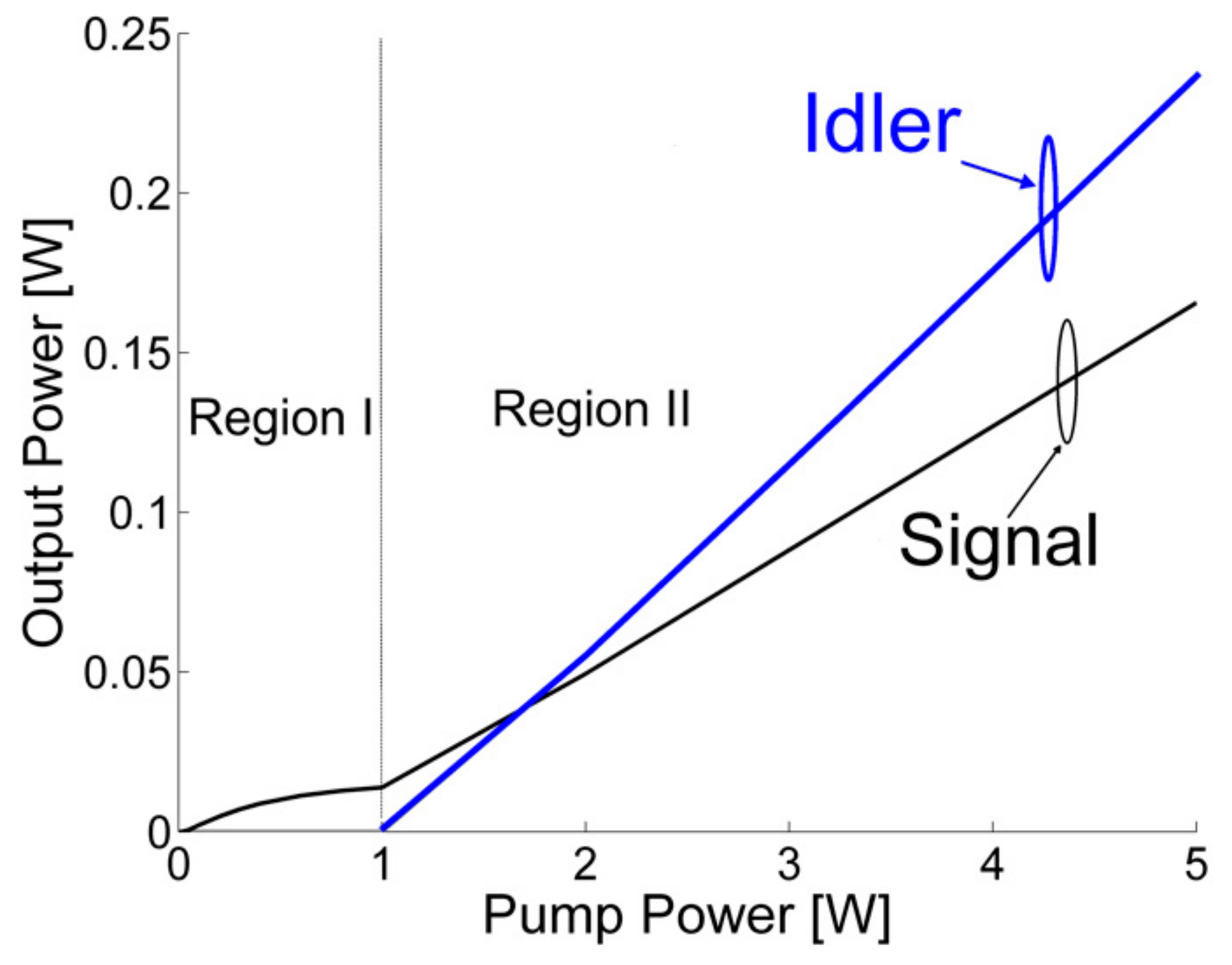
Figure 6.
Schematic diagram of a master oscillator power amplifier chalcogenide glass fiber laser proposed in [32].
Figure 6.
Schematic diagram of a master oscillator power amplifier chalcogenide glass fiber laser proposed in [32].
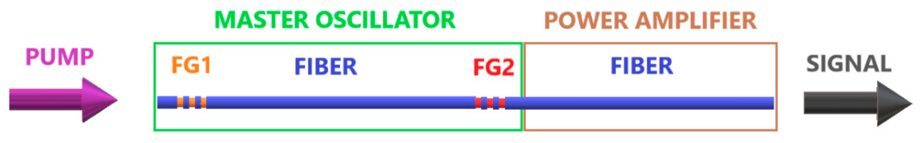
Figure 7.
Schematic diagram of a chalcogenide glass fiber laser based on a three-level scheme realized using terbium ion doping proposed in [10].
Figure 7.
Schematic diagram of a chalcogenide glass fiber laser based on a three-level scheme realized using terbium ion doping proposed in [10].

Figure 8.
Schematic diagram of laser cavity operating using cascade lasing with identified forward and backward propagating pump, signal and idler waves.
Figure 8.
Schematic diagram of laser cavity operating using cascade lasing with identified forward and backward propagating pump, signal and idler waves.

Figure 9.
Schematic diagram illustrating the principle of the coupled solution method of cascade lasing for forward propagation.
Figure 9.
Schematic diagram illustrating the principle of the coupled solution method of cascade lasing for forward propagation.
Figure 10.
Schematic diagram illustrating the principle of the coupled solution method of cascade lasing for backward propagation.
Figure 10.
Schematic diagram illustrating the principle of the coupled solution method of cascade lasing for backward propagation.

Figure 11.
Schematic diagram illustrating the principle of the relaxation method when applied to analysis of cascade lasing.
Figure 11.
Schematic diagram illustrating the principle of the relaxation method when applied to analysis of cascade lasing.

Figure 12.
Dependence of the residual, CPU time and absolute error on iteration number for: CSM, RM and SM-NRM. The pump power equals 5 W. Figure adapted from [33].
Figure 12.
Dependence of the residual, CPU time and absolute error on iteration number for: CSM, RM and SM-NRM. The pump power equals 5 W. Figure adapted from [33].

Table 1.
A summary of main characteristics of SM-NRM, RM and CSM.
| Parameter | SM-NRM | RM | CSM |
|---|---|---|---|
| Initial rate of convergence | low | moderate | moderate |
| Rate of convergence near solution | high | moderate | moderate |
| Sensitivity to initial guess | high | low | low |
| Amount of CPU time per iteration | moderate | low | low |
© 2018 by the author. Licensee MDPI, Basel, Switzerland. This article is an open access article distributed under the terms and conditions of the Creative Commons Attribution (CC BY) license (http://creativecommons.org/licenses/by/4.0/).
Share and Cite
MDPI and ACS Style
Sujecki, S. Modelling and Design of Lanthanide Ion-Doped Chalcogenide Fiber Lasers: Progress towards the Practical Realization of the First MIR Chalcogenide Fiber Laser. Fibers 2018, 6, 25. https://doi.org/10.3390/fib6020025
AMA Style
Sujecki S. Modelling and Design of Lanthanide Ion-Doped Chalcogenide Fiber Lasers: Progress towards the Practical Realization of the First MIR Chalcogenide Fiber Laser. Fibers. 2018; 6(2):25. https://doi.org/10.3390/fib6020025
Chicago/Turabian StyleSujecki, Slawomir. 2018. "Modelling and Design of Lanthanide Ion-Doped Chalcogenide Fiber Lasers: Progress towards the Practical Realization of the First MIR Chalcogenide Fiber Laser" Fibers 6, no. 2: 25. https://doi.org/10.3390/fib6020025
Note that from the first issue of 2016, this journal uses article numbers instead of page numbers. See further details here.