Article

Formal Proof of the Dependable Bypassing Routing Algorithm Suitable for Adaptive Networks on Chip QnoC Architecture

1
Laboratory of Informatics and Mathematics (LIM), University of Tiaret, Tiaret 14000, Algeria
2
Laboratoire de Conception, Optimisation et Modélisation des Systèmes (LCOMS), ASEC Team, Université de Lorraine, Metz 57070, France
*
Author to whom correspondence should be addressed.
Systems 2017, 5(1), 17; https://doi.org/10.3390/systems5010017
Submission received: 31 October 2016 / Revised: 11 January 2017 / Accepted: 20 January 2017 / Published: 22 February 2017

Abstract

:
Approaches for the design of fault tolerant Network-on-Chip (NoC) for use in System-on-Chip (SoC) reconfigurable technology using Field-Programmable Gate Array (FPGA) technology are challenging, especially in Multiprocessor System-on-Chip (MPSoC) design. To achieve this, the use of rigorous formal approaches, based on incremental design and proof theory, has become an essential step in the validation process. The Event-B method is a promising formal approach that can be used to develop, model and prove accurately SoC and MPSoC architectures. This paper proposes a formal verification approach for NoC architecture including the dependability constraints relating to the choice of the path routing of data packets and the strategy imposed for diversion when faulty routers are detected. The formalization process is incremental and validated by correct-by-construction development of the NoC architecture. Using the concepts of graph colouring and B-event formalism, the results obtained have demonstrated its efficiency for determining the bugs, and a solution to ensure a fast and reliable operation of the network when compared to existing similar methods.

1. Introduction and Related Work

The growing chip complexity and the need to integrate more and more components on the chip (e.g., processors, DSP cores or memories) imposes the trend for embedded systems moving towards Multiprocessor System-on-Chip (MPSoC). Consequently, in the new SoC paradigm, the network centric approaches, called Networks-on-chip (NoCs), are progressively becoming the main on-chip communication mediums and are the major issue in MPSoC. Indeed, integrating a NoC in the SoC provides an effective way to interconnect several Processor Elements (PEs) or Intellectual Properties (IPs) (processors, memory controllers, etc.) [1], with high levels of modularity, flexibility, and throughput. Generally, a NoC consists of routers and interconnections allowing communications between PEs and/or IPs. Communication on NoC relies on data packet exchanges. The paths used by the data packets between a source and a destination through the routers are defined by the routing algorithm. Hence, on-chip communications must have a high degree of availability; that is, a high probability of correct and timely provision of requested services. To achieve this, correctness of such communicating structure should be ensured. Formal methods can be used to verify complex MPSoC in order to ensure that these systems satisfy their functional and communication requirements [2]. Indeed, the application of formal methods helps increase confidence to building correct hardware systems. Therefore, formal methods are of essential importance to the development of such novel and complex platforms. Consequently, several previous studies propose new system formalisms based on generic and hierarchical connectors for handling the complexity of on-chip communications and data flows [3,4,5,6,7,8,9]. However, few previous studies have focused on fault tolerant communicating systems, in particular for proof validation of the on-chip communication reliabilities [10,11,12,13,14]. With an increasing complexity and reliability evolution of MPSoC, where NoCs are becoming more sensitive to phenomena generating permanent, transient, or intermittent faults, several solutions have been proposed and formalized [15,16]. The aim is to define mechanisms allowing the bypasses of the faulty nodes or regions to achieve reliability of NoC performing on-chip communications of the designed SoC. Generally, such routing schemes, before being designed, are behaviourally verified by simulation with created stimuli. This allows quick detection of the coarse errors. However, simulations cannot find all possible errors to ensure reliable functionalities before their design, and are often considered insufficient for improving the dependability of NoCs [1]. Indeed, unlike formal verification, simulations arouse a computer model by input stimuli, which is, unfortunately, not exhaustive because no extensive testing can ensure a large error coverage. Furthermore, experience has shown that if half of the errors come from carelessness during the design, the other half are from the level of the specifications.
Formal methods have the ability to produce critical systems for large industrial projects through the generation of original mathematical models that can be formally refined at various levels until the final refinement containing accurate implementation and verification details. Typically, verification by simulation does not allow the detection of all possible design errors [17]. In this paper, we propose to use the Event-B formal method, especially the correct-by-construction paradigm [18], to specify hardware systems. This paradigm offers an alternative approach to prove and define correct systems and architectures, for the reconstruction of a target system using progressive refinement through validated methodological techniques [19]. Our goal is to complete the simulation time in the design flow with a formal proof method. The preconditions for the formal development of microelectronic architectures lead to the description and/or the design of the architecture.
A large body of works has focused on the use of formal methods to verify communication systems and protocols, and model-checking methods or its composition with proving theorems are the most widely used. The work of Clarke et al. described in [20] proposed checking the temporal properties of parameterized ring networks and binary trees. A first step consists of using a free-context grammar to model the network communication systems while temporal properties are verified using a model checker. In [21], Amjad used a model checker implemented in HOL to verify AMBAAHB protocols and PDB. Bharadwaj et al. [22] proposed a broadcast protocol in a binary tree network using the SPIN model checker demonstrator. In [23], Curzon developed a structural model for Fairisle ATM switch and compared its behavioural specification using HOL. The free deadlock in the network was verified by Gebre Michael et al. using the PVS tool [24]. Some works, which are based on semi-formal methods, were also proposed to detect and debug failures. For example, Chenard et al. proposed assertion listeners PSL [25,26] which were synthesized using NGC tool [27] in a NoC. Analytical approaches do not cover the dynamic behaviour and performance of a system, but rather analyse it statically. Model checking, which has been adopted in this paper, is an automated technique to verify each model of a system satisfies its specifications [28]. The model is described as a state machine and the specification is described in a temporal logic. A model control algorithm uses the transition function associated with the state machine to explore the state space and define the states that do not meet the specifications. If a state is found, its traces leading to this state are reported. If such a state is not found, the system is proved correct. Model checking is widely adopted by academic and industry communities, mainly because it is a fully automatic model. The major problem is its combinatorial blow-up of the number of states that have to be explored, usually called state space explosion. This severely limits the scalability of model checking. Theorem proving is a technique where the evidence of a mathematical theorem is formalized so that a computer program can guarantee its accuracy. The main advantage of the theorem is the ability to deal with the parametric systems.
The verification of SoC communications [29] describes the main challenges in the design of NoCs [1] and discusses some aspects of audit networks where formal methods are useful. Dynamic reconfigurable NoCs are adequate for FPGA-based systems, where the main problem arises when IP components must be defined dynamically at run time. Given the rapidly changing and highly complex MPSoCs, the constraints related to the complexity and the increasing number of interconnected modules or IP such as the cost and performance must be resolved. Current communications of NoCs implement the data transmission between the interconnected nodes. Sometimes the communication of this kind of networks is difficult or even impossible. This is the main reason why XY fault-tolerant routing algorithms have been developed [30]. These algorithms allow bypassing faulty or unavailable regions through the error detectors introduced inside the network in order to ensure that the data packets are not loss. Routers can control the miss-routing of previous detectors (e.g., packet on the path XY, etc.). In addition, new techniques and adaptive fault-tolerance routing with error detection and path routing based on the well-known XY turn model have been introduced. In the case of these algorithms, zones corresponding to already detected faulty nodes or unavailable regions in the NoC are defined. As routers can control if previous switches have performed routing errors (e.g., packet out of the XY path, etc.), the neighbour routers of these zones must not send data packets toward these faulty routers or unavailable regions. To achieve this, chains or rings around the adjacent faulty nodes or regions are formed in order to delimit rectangular parts in the NoC covering all the faulty nodes or unavailable regions. In these chains or rings of switches, the routing tables are modified and differ from the standard tables related to the XY routing algorithm. These specific switches integrate in their tables additional routing rules allowing to bypass the faulty zones or regions dedicated to dynamic IP/PE instantiations, while avoiding starvation, deadlock, and livelock situations [19]. On the other hand, formal studies have only focused on NoC performance [31,32], latency [33], bandwidth [34], estimation of consumption [34], error detection and correction [35,36], and required and used logic area. Others propose methods of free-deadlock routing [37,38] to characterize the traffic.
This paper aims to investigate event-B concept and its application to specify and verify formally the correctness of the SoC communications. The contributions are twofold: to demonstrate the NoC behaviour; and to prove the dependability of a proposed fault tolerant routing algorithm used in a specific NoC. More precisely, in our formal approach, by considering the architecture of routers and the defined communication rules of the specific routing algorithm under normal and fault conditions, we ensure a correct transmission of data in the network and a reliable functionality. This is done from the checking criteria being invariants of behavioural of logic and communication blocks constituting the routers, and designed for bypassing faulty or unavailable regions in the NoC. We also aim to demonstrate the step-wise construction of the adaptive NoC, which can be useful for a pre-silicon verification by testing the behaviour of the NoC architecture in a virtual environment with a formal verification tool.
The remainder of this paper is organized as follows. Section 2 presents an overview of the event-B method showing the NoC architecture studied with the audit results of the formal verification. In this section, the behavioural modelling of the NoC with its basic element switches are detailed by describing the architecture of the fault tolerance and the model description. This section also details the proofs of the proposed fault tolerant modified XY routing algorithm associated to the modelled NoC to overcome some faulty events encountered in the network in order to maintain the dependability during the communication operations. Section 3 discusses the results obtained from the various levels of formal modelling detailed in Section 2. Finally, Section 4 concludes this paper along with the future work.

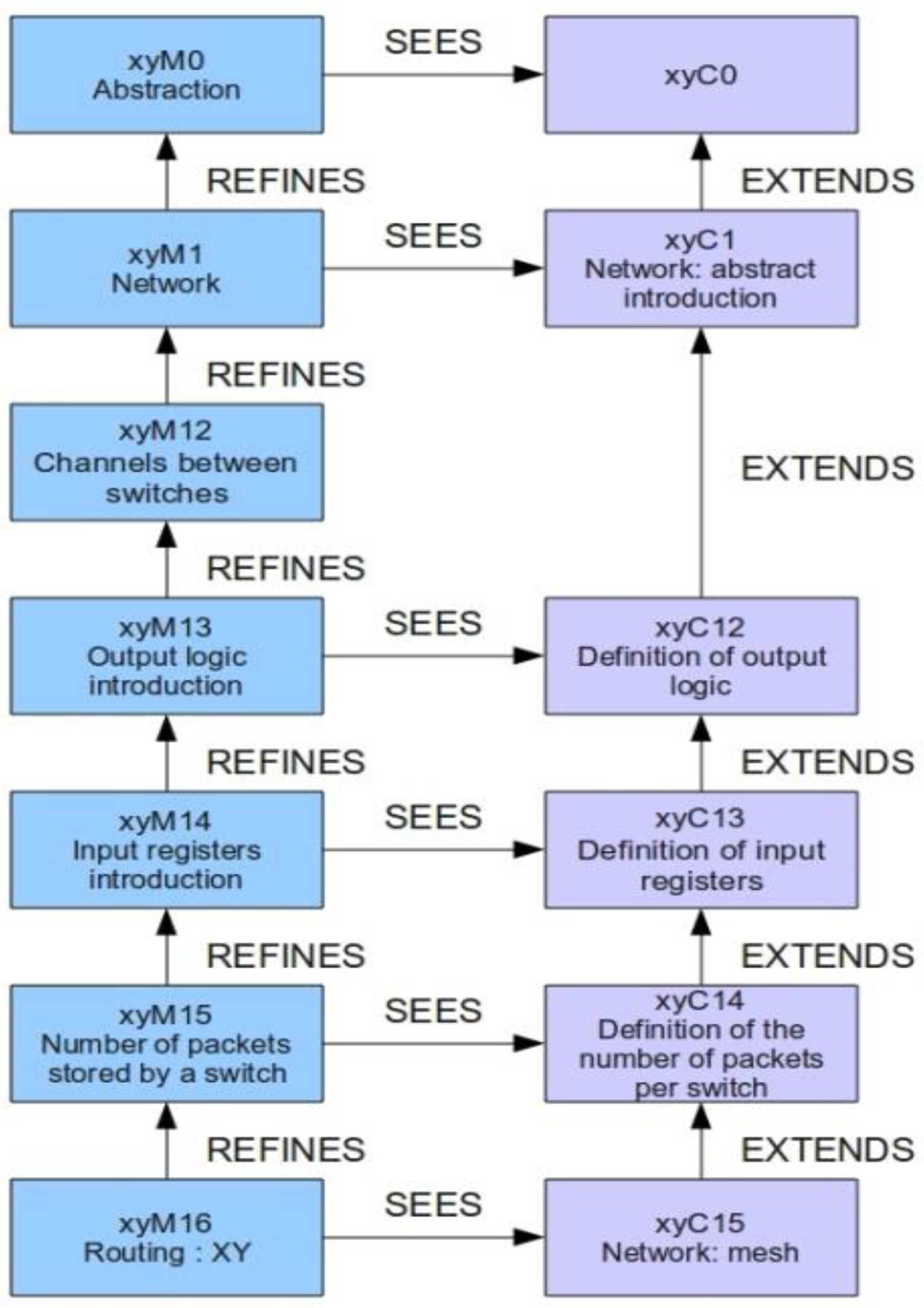
2. Stepwise Specification of the System Using Event-B

2.1. Definition of Event-Band and Proof Obligations

The main reason for selecting Event-B as the modelling language is its the refinement feature which allows a progressive development of models. Moreover, Event B is also supported by a complete RODIN toolset [38] providing features including refinement, proof obligations generation, proof assistants and model-checking facilities. The Event B modelling language can express theorems or safety properties, which are invariants, in a machine corresponding to the system [39]. Event B allows a progressive development of models through refinements. The two main structures available in Event-B are:
-
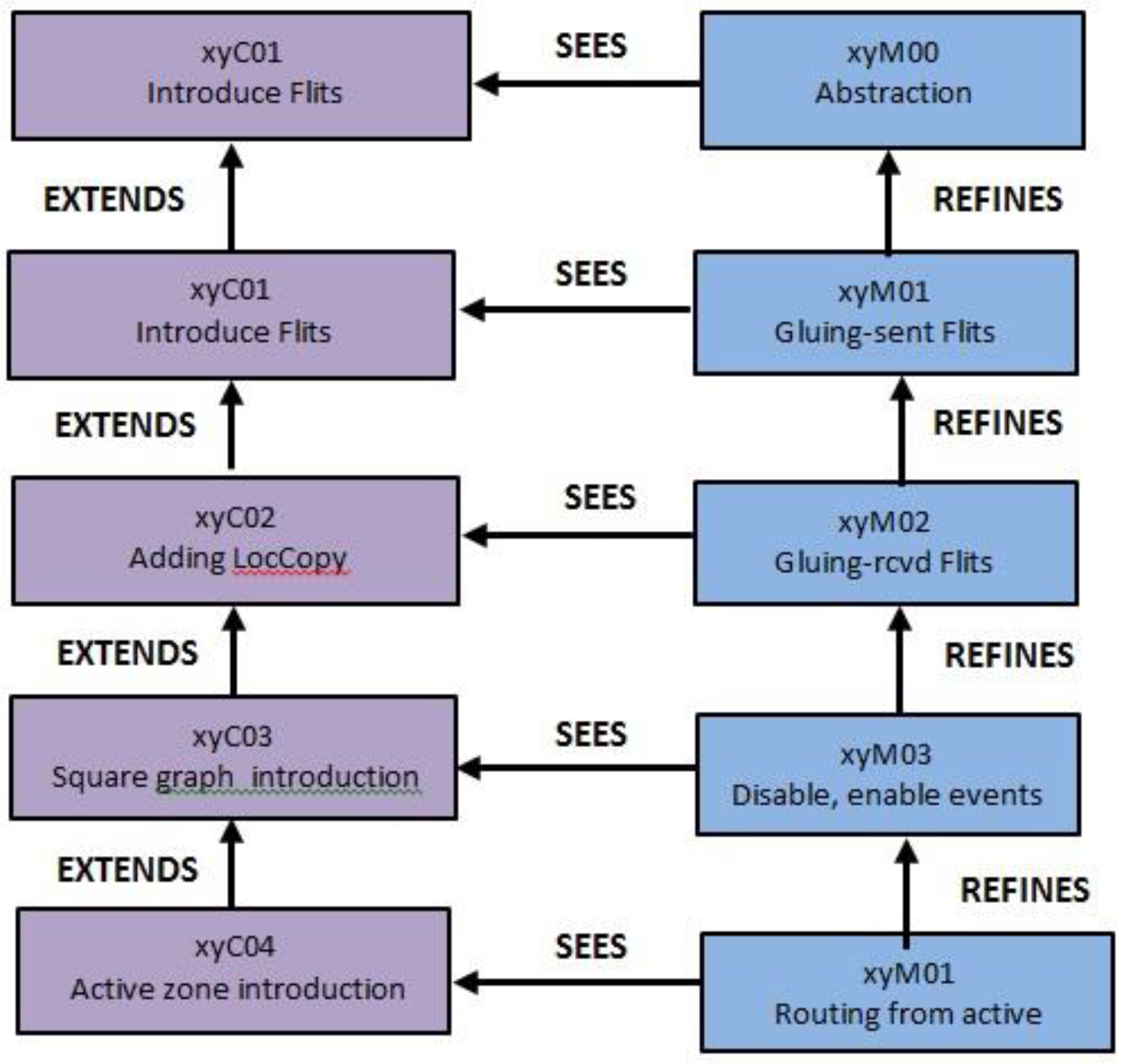
Contexts, which express the static information about the model.
-
Machines, which express dynamic information about the model, invariants, safety properties, and events.
An Event B model is defined either as a context or as a machine. A machine organizes events (or actions), which modify the state variables and uses static information defined in a context. The refinement of models provides a mechanism for relating an abstract model and a concrete model by adding new events or variables. This feature allows to develop gradually Event-B models and to validate each decision step using the proof tool. The refinement relationship should be expressed as follows: a model M is refined by a model P, when P simulates M. Thus, from a given model M, a new model P can be built and asserted to be a refinement of M describing the architecture. Model M is an abstraction of P, and model P is a refinement (concrete version) of M. Likewise, context C, seen by a model M, can be refined to a context D, which may be seen by P (see Figure 1). The final concrete model is close to the behaviour of the real system that executes events using real source code. The refinement of a formal model allows us to enrich the model via a step-by-step approach and is the foundation of our proposed correct-by-construction approach. Refinement provides a way to strengthen invariants and to add details to a model. It is also used to transform an abstract model to a more concrete (real) version by modifying the state description. This is done by extending the list of state variables (possibly suppressing some of them) and by refining each abstract event to a set of possible concrete versions, and by adding new events.
The proofs obligation defines what is to be proved for an Event-B model. These proofs are automatically generated and concern Invariant, Preservation, Feasibility, Fusion, and so on. The RODIN Platform tool [40], called Proof Obligation Generator, decides what is to be proved in order to ensure the correctness of the model. Therefore, just to check contexts and machine texts and to decide what is to prove in these texts, there are eleven rules for the proof obligation all defined and labelled within the Robin platform. Actually, the refinement-based development of Event B requires a very careful derivation process, integrating possible tough interactive proofs for discharging generated proof obligations, at each step of development. The automatic prover is designed in order to drive the heart’s mode in which the evidence Prove (pr) command is tried on each proof obligation. An automatic mode simply stores the maximum tempted strength for each obligation, which is the level of automatic proof obligation. On the other hand, the interactive demonstration allows the operator to decide him/her self what proof commands are applied. The sequence of commands that a user has chosen to demonstrate an obligation is stored along with the state of proof.

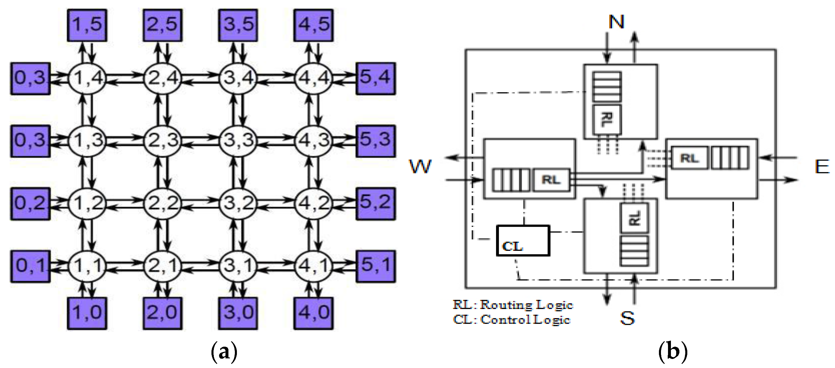
2.2. NoC Architecture Description and Modeling

The network transmission is realized through routers constituting the network, and by using switching techniques of data packets constituted of messages and routing rules [1]. Usually, the network has a grid-like form and is built with on-chip routers characterized by a 2D mesh topology, Ack/Nack flow control, and store-and-forward buffering strategy, which avoid deadlock situations. Figure 2 illustrates the mesh-network (4 × 4 mesh topology) where peripheral switches are associated to a PE. Therefore, boundary switches are connected to one PE and with two or three neighbours, whereas other nodes are connected to four neighbours. Each NoC element (PE or router) possesses a specific address but only PEs act as emitter and receiver of messages through the network. Thus, in a n × n 2D mesh, a node or switch K is identified by a two element vector (kx and ky), 1 ≤ kx, kyn, where kx and ky are the coordinates of dimension x and y, respectively. The routers communicate with other neighbours in the four possible directions through a fixed number of packets. For this purpose, each switch has four incoming and outgoing ports from which it can receive and send the packets (see Figure 1). Four pairs of ports towards other adjacent nodes are named, respectively, West, North, East and South. In our case study, we consider a Quality-of-Service NoC (QNoC) switch (see Figure 2b) [1] which consists of routing logic and control logic with inputs/outputs for each direction. This microelectronic architecture communicates with four neighbouring elements.
The computing elements associated with the NoC network communicate through messages. A message consists of a fixed number of packets and is based on a wormhole flow control. The number of packets Np in a message is not fixed by the network (Np ≥ 1). The format of a packet is shown in Figure 3. The first field denotes the destination address whose size depends on the total number of units constituting the NoC communication network. The second field contains the information about the size of the packet, while the third field contains the (user-ID) identification number of the packet. We consider the size of the ID field to be less than or equal to the size of the message, and it is never zero. The last field contains the data to be transmitted. Packets can flow in different directions depending on the status of the router (free busy or failed) but the communication units in a single packet (conflicts) must follow the same path.
In the next subsections, we detail the formal specification that has been validated from the RODIN Event-B software. The refinements of the formal proof demonstrating the dependability of the proposed fault tolerant routing algorithm suitable for adaptive NoC is also given. Therefore, we give the axioms and invariant express results obtained under RODIN toolset environment proving the efficiency of the proposed fault-tolerant adaptive routing algorithm based on the XY and turn model routing schemes.

2.3. NoC Formal Development and Discharge Obligations

An incremental development of a NoC architecture using the Event-B formalism [41] and the formalization of the architecture is presented from an abstract level down to a more concrete level in a hierarchical way (see Figure 4).
- The first model xyM0 is an abstract description of the service offered by the NoC architecture (see Figure 5): the sending of a packet (p) by a source switch and the receiving of (p) by a destination switch.
A set of switches (NODES); a set of packets (MSG); a function src, associating packets and their sources; and a function dst, coupling packets and their destinations, are defined in the context xyC0. The machine xyM0 uses (sees) the contents of context xyC0, and with these, describes an abstract view of the service provided by the NoC architecture:
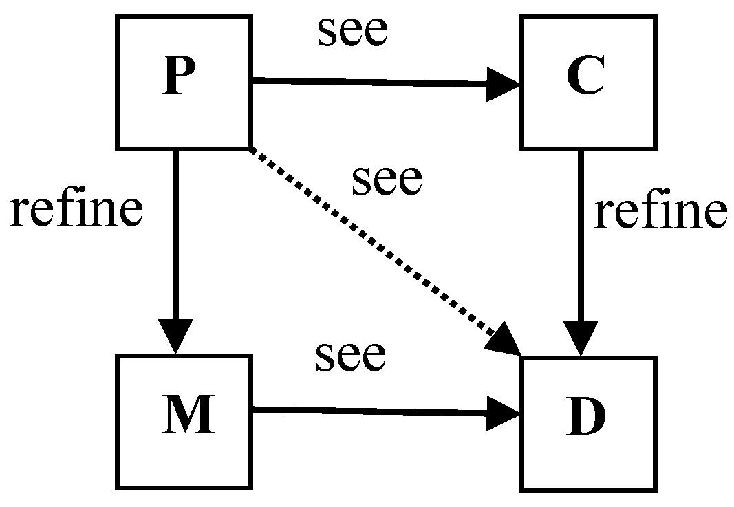
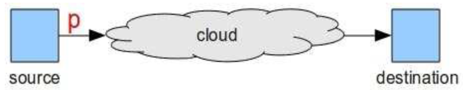
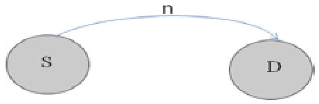
  • An event SEND presents the sending of a packet (m), by its source (s), to a switch destination (d).
  • An event RECEIVE depicts the receiving of a sent packet (m) by its destination (d).
Moreover, the model xyM0 allows us to express some properties and invariants:
ran(received) ⊆ran(sent)
This invariant ensures that each packet received by a destination switch has been sent by a source switch.
- The machine xyM1 refines xyM0 and introduces a network (agraph) between the sources and destinations of packets (see Figure 6). Some properties on the graph are defined in context xyC1: graph is non-empty, non-transitive and is symmetrical.
The events in xyM0 are refined:
  • Event SEND: When a source sends a packet, it is put in the network.
  • Event RECEIVE: A packet is received by its destination, if it has reached the destination.
New events are also introduced by xyM0:
Event FORWARD (see Figure 7): in the network, a packet (p) transits from a node (x) to another node (y), until the destination (d) of packet (p) is reached.
  • Event DISABLE: A node is disabled. The node is not allowed to communicate with its neighbours (failure, etc.). During the disabling of some nodes, we ensure that the packets transiting in the network will eventually reach their destinations (either after a reconfiguration of the network or by always keeping a path to destinations available).
  • Event RELINK: This event models the reconfiguration of the network. Disabled nodes are re-enabled: the links between them and their neighbours are restored, therefore allowing communications and packets transfers. The reconfiguration of the network helps in demonstrating the safety of data transmission between a source switch and a destination switch.
The machine xyM1 also presents some properties of the system:
ran(received) ∩ ran(store) = ∅
This invariant demonstrates that a packet (p) sent by a source is either traveling in the network (store) or is received by a destination.
- The second refinement decomposes the event FORWARD of xyM1 into two events:
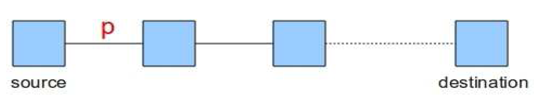
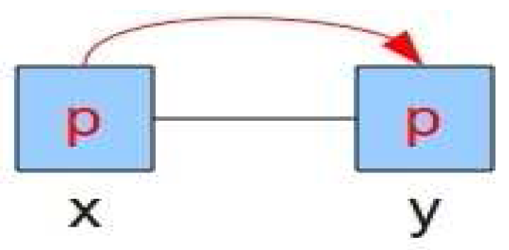
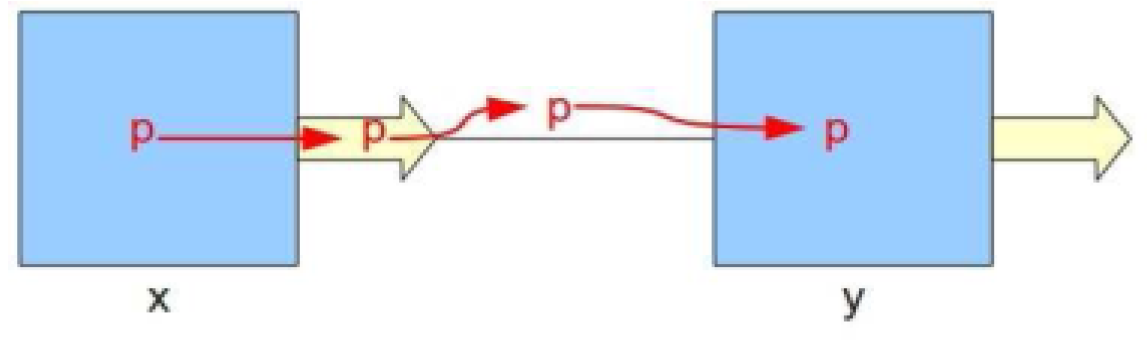
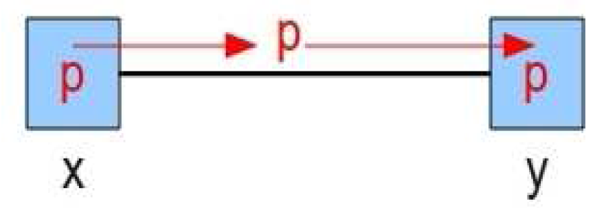
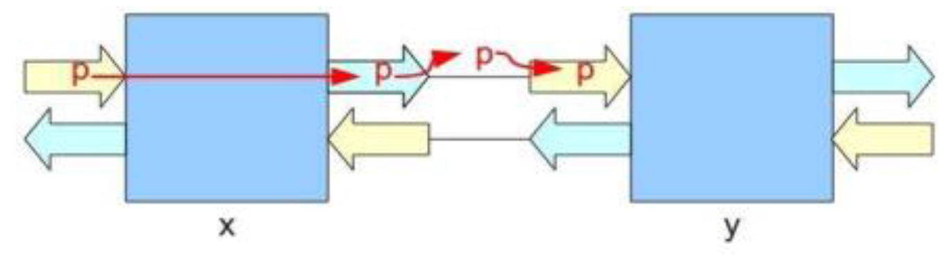
  • A refinement of the event FORWARD depicts the passing of a packet (p) from a switch (x) to a channel (ch), leading to a neighbour (y) (see Figure 8).
  • An event FROM_CHANNEL_TO_NODE models the transfer of a packet (p) from a channel (ch) to a connected switch (n) (see Figure 8). The machine xyM12 also defines some properties:
    ran(c) ∩ran(switch) = ∅
The invariant expresses that each transmitted packet is either in a channel or in a switch. A sent packet cannot be in a channel and in a switch at the same time.
- The third refinement allows us to introduce the structure of a switch gradually. We express, in xyM13, that the switches possess output ports (see Figure 9). The abstract event FORWARD is further decomposed:
  • The refinement of event FORWARD adds the fact that a packet (p), which is leaving a switch (x) and heading for a neighbour (y), first enters the output logic (op) of the switch (x) leading to (y).
  • A new event OUTPUT_BUFFER_TO_CHANNEL models the transition of a packet (p) from an output port (op) to a channel (ch) leading to a target switch (n).
Moreover, new properties and invariants are defined in xyM13:
inv1 : ran(chan) ⊆ ran(sent)
inv2 : ran(outputbuffer) ⊆ ran(sent)
inv3 : ran(outputbuffer) ∩ ran(chan) = ∅
The invariant inv1 expresses that each packet transiting in a channel (ch) has been sent by a source (s); inv2 demonstrates that each packet transiting in an output port (ch) has been sent by a source (s); and inv3 presents the fact that a packet is either in an output port or in a channel, the packet cannot be in an output port and a channel between two switches at the same time.
- The fourth refinement (xyM14) adds input ports to the structure of a switch (see Figure 10).
The event SEND is refined: when a switch source (s) sends a packet (p), the packet (p) is put in an input port (ip) of the switch (s). The actions described by the abstract event FORWARD are decomposed:
  • The event SWITCH_CONTROL, a refinement of FORWARD, models the passing of a packet (p), from an input port (ip) of a switch (x), to an output port (op) leading to a switch (y).
  • The event OUTPUT_BUFFER_TO_CHANNEL presents the transition of a packet (p), from an output port (op), to a channel (ch) leading to a target switch (n).
  • The event FROM_CHANNEL_TO_INPUT_BUFFER demonstrates the transition of a packet (p) from a channel (ch) to an input port (ip) of a target switch (n).
The machine xyM14 also presents properties and invariants:
inv1 : ran(inputbuffer) ⊆ ran(sent)
inv2 : ran(outputbuffer) ∩ ran(inputbuffer) = ∅
inv3 : ran(inputbuffer) ∩ ran(chan) = ∅
The invariant expresses that each packet transiting in an input port (ip) has been sent by a source (s); inv2 demonstrates that each packet is transiting either in an output port (op) or an in input port (ip); and inv3 presents the fact that a packet is either in an input port or in a channel: the packet cannot be in an input port and a channel between two switches at the same time.
-
The fifth refinement introduces the storage of packets in a switch: each output port of a switch can store a number of packets up to a limit (outputplaces) of three messages. Packets can be blocked in a switch, because of the “wait” or “occupation” signals from the neighbours. The event SWITCH_CONTROL is refined, and adds the fact that, following the transition of a packet from an input port of a switch (x) to an output port, if the switch (x) is not busy anymore, it sends a release signal to the previous switch linked to the input port. A new event RECEIVE_BUFFER_CREDIT models the receiving of a release signal by a switch (n).
-
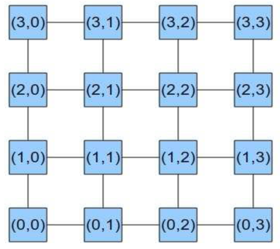
The last model xyM16 describes the architecture of the network (graph): the graph has a mesh topology (see Figure 11). A numerical limit (nsize) is introduced to bound the number of routers in the dimensions x and y of the network topology; the network will be a regular 2D-Mesh, with a size of (nsize × nsize); each switch is coupled with unique coordinates (x; y), with x 2 [0..nsize − 1] and y 2 [0..nsize − 1].
This coordinate system allows it to be more precise on the neighbours of each switch, as shown in Figure 11. This model also gives a fine-grained description of the structure of a switch (see Figure 12):
A switch generally has four output ports and four input ports (usually labelled N, S, E and W), used for communication with neighbours. However, two more cases are distinguished:
Boundary switches at the corners only have two output ports and two input ports (N-E, N-W, S-E, and S-W).
Other boundary switches have three output ports and three input ports (N-S-E, and N-S-W).
Moreover, this model also introduces the XY routing algorithm:
D: destination. Coordinates (Dx, Dy)
C: current node. Coordinates (Cx, Cy)
if (Cx>Dx) :
return W; (Case 1)
if (Cx<Dx) :
return E; (Case 2)
if ((Cx = Dx) ∨((Cx>Dx) ∧W is blocked) ∨
((Cx<Dx) ∧E is blocked)):
if (Cy <Dy):
return N; (Case 3)
if (Cy >Dy):
return S; (Case 4)
The cases of the XY routing algorithm are matched with refinements of event SWITCH_CONTROL:
  • SWITCH_CONTROL_LEFT models Case 1: A packet (p) is transmitted from an input port of a switch (x) to an output port, resulting in a neighbour (y) located at W. This event is triggered if the x-coordinate of the destination (d) (of the packet (p)) is inferior to the x-coordinate of the current node (x).
  • SWITCH_CONTROL_RIGHT models Case 2: A packet (p) is transmitted, from an input port of a switch (x), to an output port, leading to a neighbour (y), located at E. This event is triggered if the x-coordinate of the destination (d) (of the packet (p)) is superior to the x-coordinate of the current node (x).
  • SWITCH_CONTROL_UP models Case 3: A packet (p) is transmitted, from an input port of a switch (x), to an output port, leading to a neighbour (y), located at N. This event is triggered if the y-coordinate of the destination (d) (of the packet (p)) is superior to the y-coordinate of the current node (x), and either, if the x-coordinate of the destination (d) is equal to the x-coordinate of the current node (x), or if the packet (p) cannot transit along the x-axis.
  • SWITCH_CONTROL_DOWN models Case 4: A packet (p) is transmitted, from an input port of a switch (x), to an output port, leading to a neighbour (y), located at S. This event is triggered if the y-coordinate of the destination (d) (of the packet (p)) is inferior to the y-coordinate of the current node (x), and either, if the x-coordinate of the destination (d) is equal to the x-coordinate of the current node (x), or if the packet (p) cannot transit along the x-axis.
Table 1 gives the number of proofs obligations which are automatically discharged proving the checking of criteria for each considered level of abstraction and step by step. It can be noted that for context xyC15 and machine xyM14, there are more interactive proofs that automatic counterparts. This is explained by the fact that a majority of these interactive proofs are quasi-automatic: the proofs do not require significant efforts (no importing hypotheses, simplifying goals, etc.).

2.4. Formal Devlopement of the Proposed Fault Tolerant Routing Algorithm and Discharge Obligations

In our case study, we consider an algorithm [1] that is a partially adaptive routing algorithm allowing both routing of messages in networks incorporating regions that are not necessarily rectangular, and all nodes, which are not completely blocked by faulty nodes. The considered routing scheme designed for a 2D mesh topology and based on the turn model and XY routing algorithm allows the handling of faulty nodes and regions of the chip [1]. More precisely, the switch uses a routing algorithm based on the classical XY algorithm that can be used initially in the network and which relies on the fact that the packets are routed according to X axis, and then to the Y axis of the array. If the routing packets encounter faulty nodes or regions that prevent them from going through XY paths, then the proposed routing algorithm allows circumvention of the faulty area(s) of the network. To achieve this sort of bypassing, modified routing rules are performed by the nodes surrounding network’s faulty areas according to the strategy detailed below.
Definition 1.
In a 2D mesh, a node is called an even (respectively, odd) node if the sum of its coordinates (x and y dimensions) is an even (respectively, odd) number.
The regular placement of even and odd nodes in the network is depicted in Figure 12. Each type of node is surrounded by elements of other types, even nodes by odds and vice versa. We distinguish two types of functioning of each node, activated and deactivated modes, which define activated and deactivated areas of a network as follows:
Definition 2.
One of the activated area of a network is a minimal rectangular area which envelops all faulty nodes or regions in the network.
If a network does not have faulty nodes or regions, there is no activated area. Otherwise, a network can contain only one activated area. All nodes (except faulty nodes or regions) belonging to an activated area are activated. An activated area cannot have at the same time an odd (even) node at its top right-hand corner and an even (odd) node at its bottom left-hand corner.
Definition 3.
One of the deactivated areas of a network is the rest of the network which does not belong to the activated area.
If a network does not have an activated area (no faulty nodes or regions), the whole network is deactivated. All nodes belonging to a deactivated area are deactivated. Figure 13 presents a network with an activated area formed around a faulty node. In this case, only the nodes wrapping the faulty node become activated. The nodes belonging to the rest of the network do not change their mode, and remain deactivated. A deactivated node routes a data packet according to the XY algorithm. Firstly, it routes along the X dimension and then along the Y dimension until the packet reaches its final destination. If a packet, before reaching its final destination, reaches the activated area’s boundary, new routing rules are applied.
Accurately, the activated nodes (boundary nodes of an activated zone) do not obey the same set of rules as deactivated nodes. These rules are presented in the following:
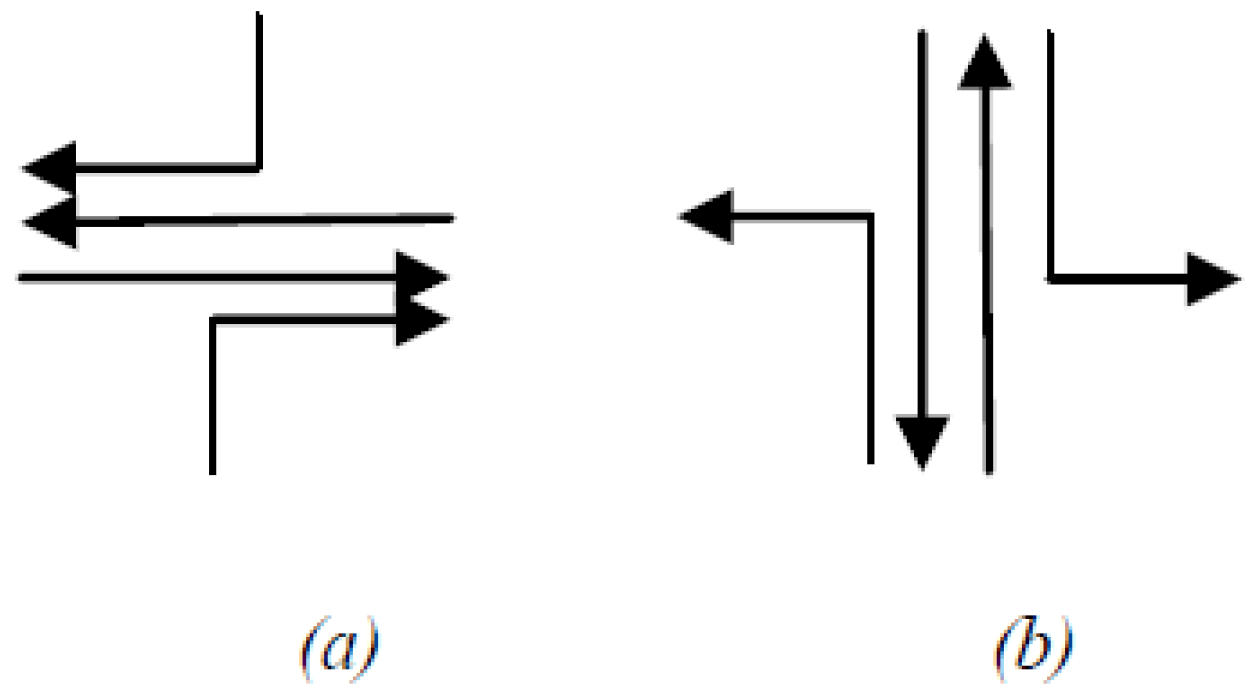
  • Rule 1. All packets in the active region can be routed only along the X-axis.
  • Rule 2. An activated node cannot route a packet from North to East side and vice versa.
  • Rule 3. An activated node cannot route a packet from South to West side and vice versa.
  • Rule 4. All activated nodes cannot route a packet from North to South and vice versa.
Each node can communicate directly with four neighbouring nodes on the network, which means that there are sixteen (24 = 16) possible pathways from one node in a mesh to other neighbouring nodes. To avoid routing loops, data packets cannot return to the sender node, hence the number of pathways left is twelve (24 − 4 = 12). To avoid livelock situation, it is necessary to eliminate the packets going in opposite direction of the authorized one, (Figure 14a) which leaves only eight possible routes. To route packets towards their final destination in an active zone, four paths are allowed and the others are blocked (see Figure 14b).
The network is scanned regularly in order to detect online the occurred faulty nodes. If a new faulty node or region is detected, the activated node’s routing tables are updated with the new information about the positions of new faulty nodes or regions. More precisely, to achieve these routing decisions from the modified routing rule tables, each switch holds one input register in each of its ports (see Figure 1). Therefore, all packets pass through the input registers. Once the packets have arrived and are stored in the input registers, the routing logic block specifies the next direction (according to their authorized turns and directions) of the packets which are transmitted to the associated logic output port of the output direction. Consequently, the information contained in the routing tables help activated nodes to take routing decisions. For example, an activated area with the minimal number of active nodes, which forms a ring around faulty nodes, does not route the packets the same way as an activated area having more activated nodes. In the latter case, the packet not only uses the ring of activated nodes to get around the faulty nodes or regions, it can also use other activated nodes to route its packets. Before specifying and verifying the bypass algorithm, we propose a specification of conduct of event defining the bypass active zone around faulty nodes (knowing that there may be several faulty nodes in the network, thus more active zones can be constructed), it is proposed to use a colouring algorithm.

2.4.1. Vertex Colouring Algorithms

Symmetry breaking has always been a central problem in distributed systems. Several techniques have been developed for graph colouring algorithms including Maximal Independence Set (MIS). An algorithm for vertex colouring is a process of marking a graph [42] where the goal is to assign labels to the vertices of the graph. Labels are often treated as colours. Therefore, it is called coloured graph algorithm. Colouring/labelling is designed so that no two adjacent vertices share the same colour/label: an appropriate colouring of a graph G = V, E (with V the set of vertices of G and E the set of its edges), using a set of colours (N | COLOURS = 1 .. N) is a function f such that (F: V 3 COLOURS | f (i) = f 3 (j) where j, i ∈ E). The minimum for N is satisfied if it is called the chromatic number of G. These rules are generally applied to simple graphs (connected, reflexive, undirected, and unweighted). Several algorithms have been developed to colour a chart. As described in [43], the vertex colouring algorithms can be classified into two categories:
-
Centralized algorithms [44,45]: The word “central” implies that there is at least one “administrator” who decides to graph colouring.
-
Distributed algorithms [42,43,44,45]: These new algorithms involve all vertices of the graph that is coloured and the tops have their own “intelligence”. Usually, they choose their own colours using random probabilities when they have chosen the same colour as their neighbours, and, when they have a good colour, in this case, they withdrew from the uncoloured curve [42,43,44,45]. In this work, we focus on the development of algorithms using distributed techniques. In fact, there is little or no verification of the accuracy of previous algorithms [42,43,44,45] considering some random numbers to define the process of secure coloration.
There are many practical applications of colourful graph algorithms that include:
-
Planning graph colouring [46] can be used to control a set of nodes. Two nodes are considered adjacent when they may occur simultaneously. The aim is to prevent adjacent nodes occurring at the same time. However, in our case, there may be two nodes that have the same job but two test nodes cannot fix the failed node at the same time.
-
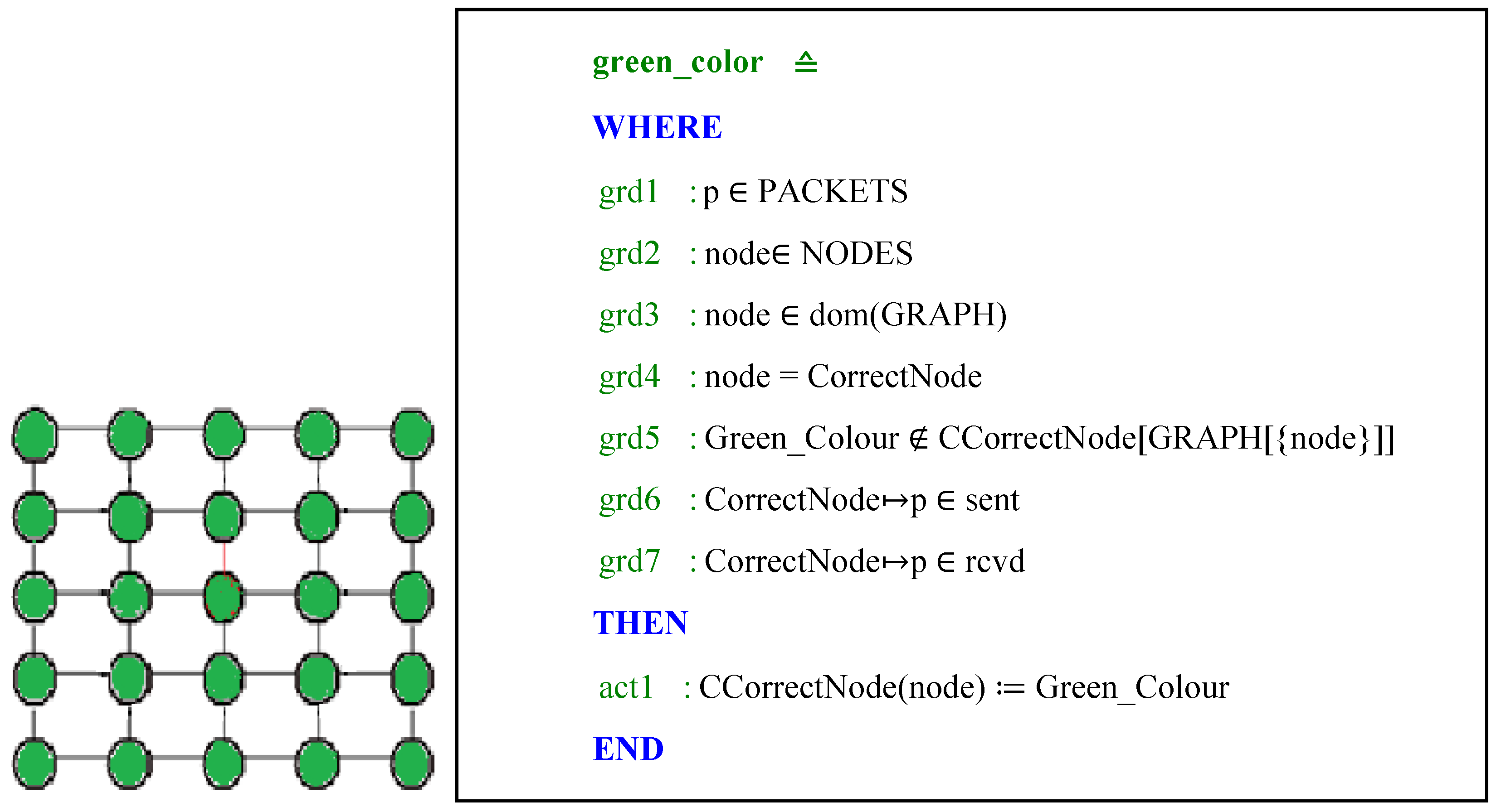
Each correct node must be coloured in green; a correct node is a node that can send and receive packets.
-
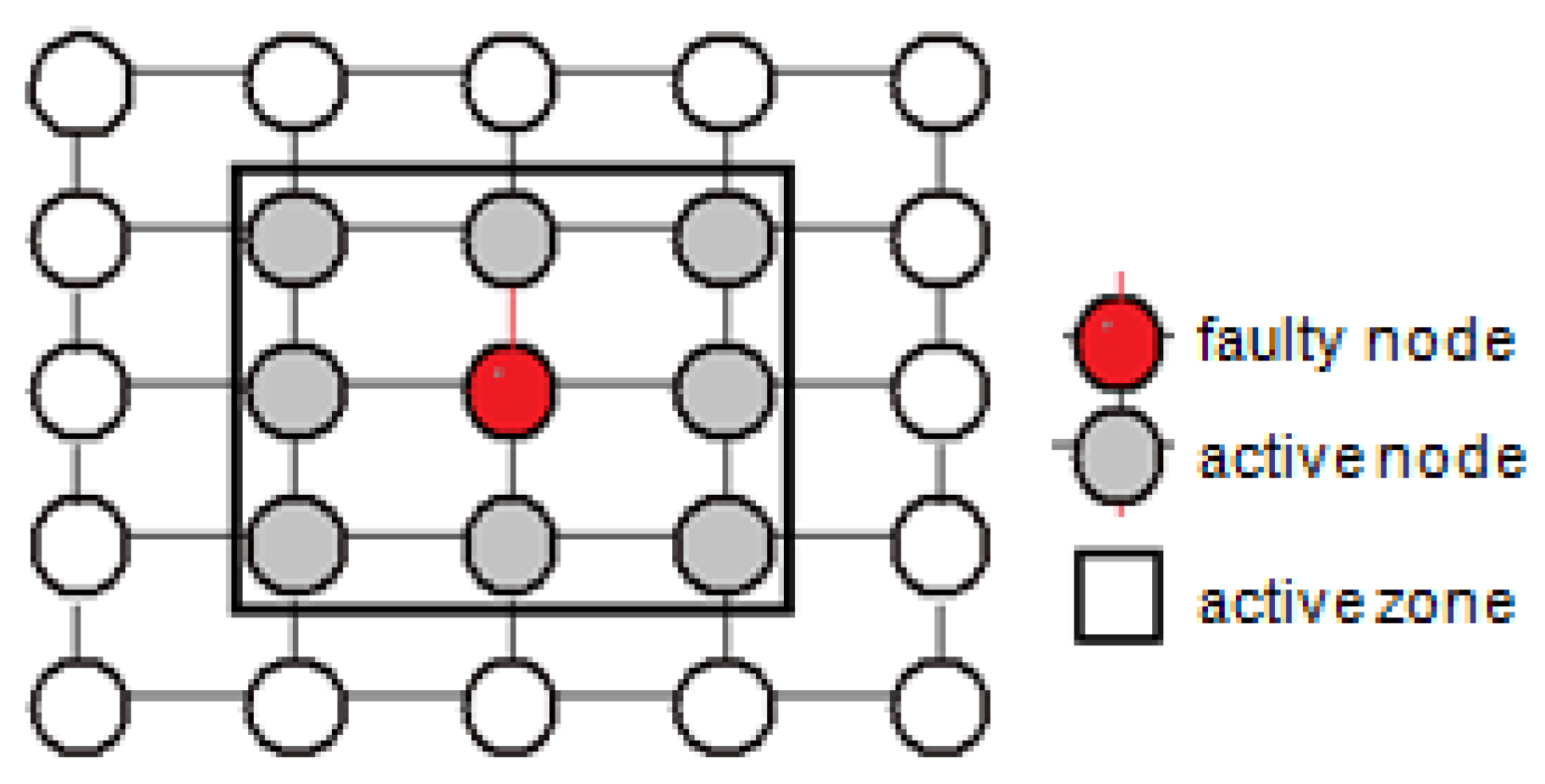
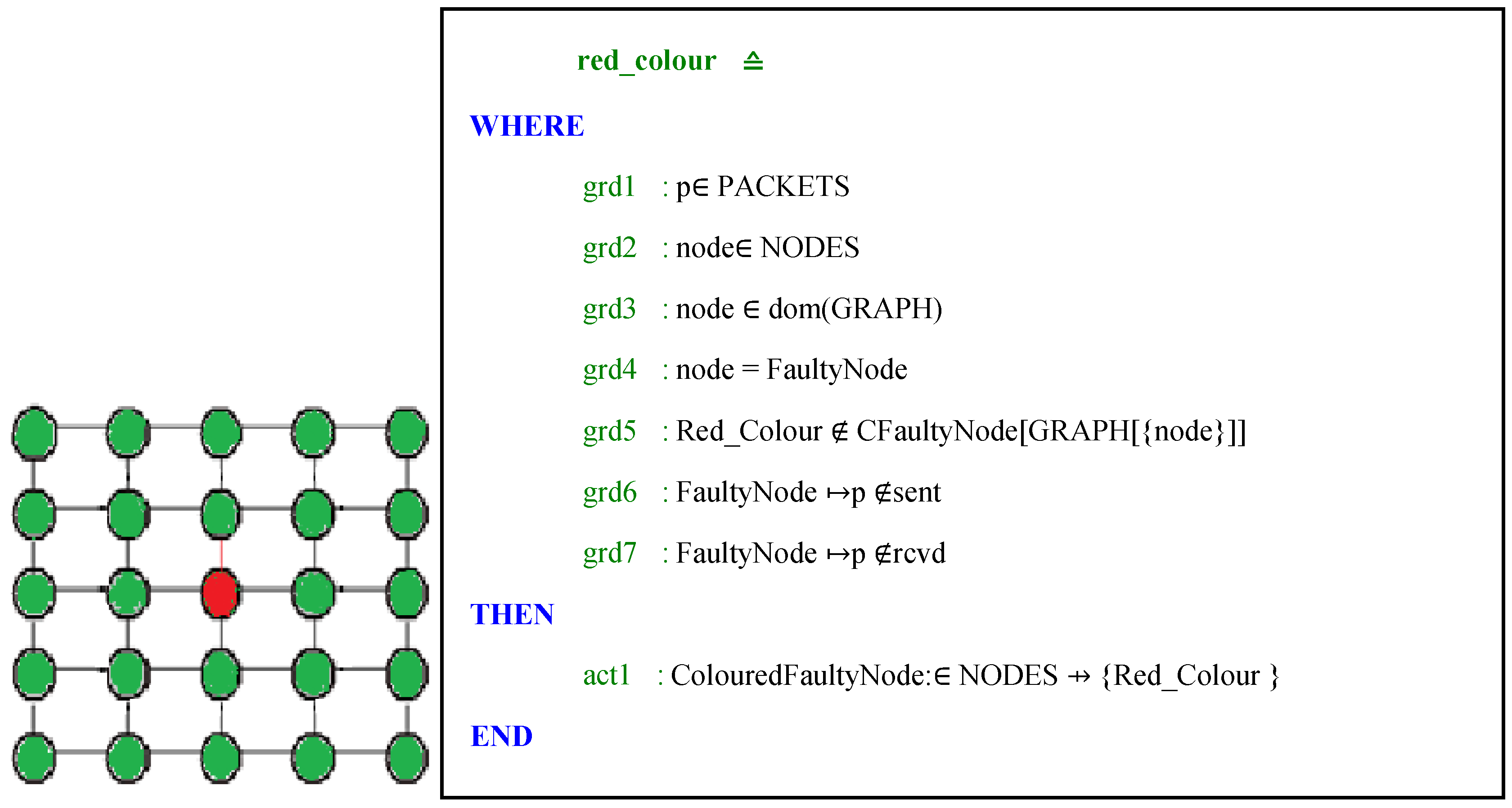
Each failed node must be coloured in red; a failed node is a node that cannot send or receive packets or one of the two.
-
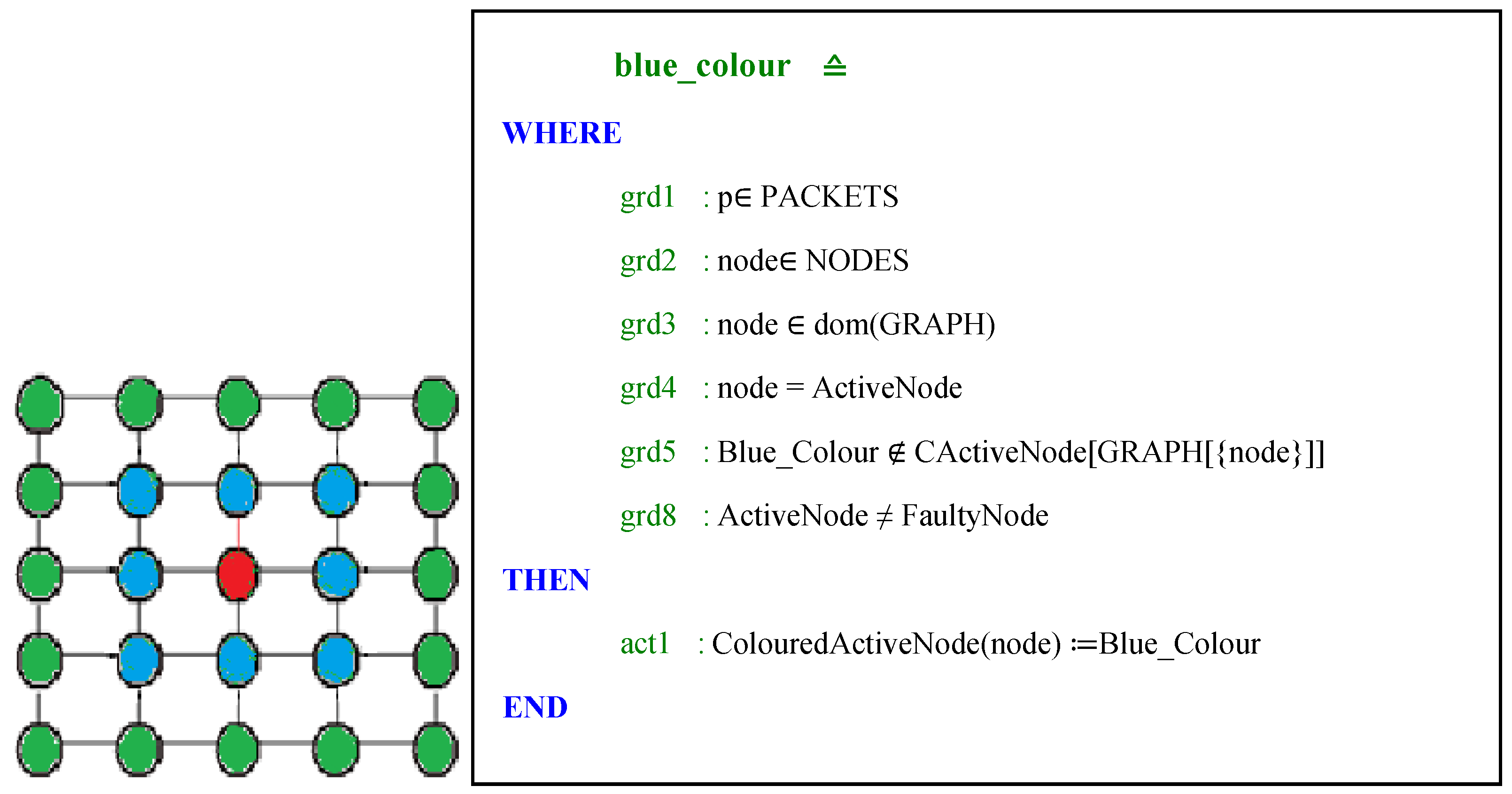
Each active node must be coloured in blue; an active node is a neighbouring node to a failed node.

2.4.2. Formal Specification of the System

Abstract level: We start with an abstract specification of the problem by defining the role of the network send and receive packets (See Figure 15). Thereby, two sets will be defined in this level; existing nodes (NODES) and packets (PACKETS) sent by a single source (src) and received by a single destination (dst). Sources are different from destinations. The following axioms are described in the context of the abstract level as follows:
We define the variable rcvd, which allows us to perform the SEND and RECEIVE actions. The following invariants are described in the abstract level of the machine as follows:
Systems 05 00017 i001
The initial values of variables are empty:
Systems 05 00017 i002
The SEND event is action: act1: sent ≔ sent∪{s↦p} and RECEIVE event is action: act2: rcvd := rcvd ∪{d↦p}
-
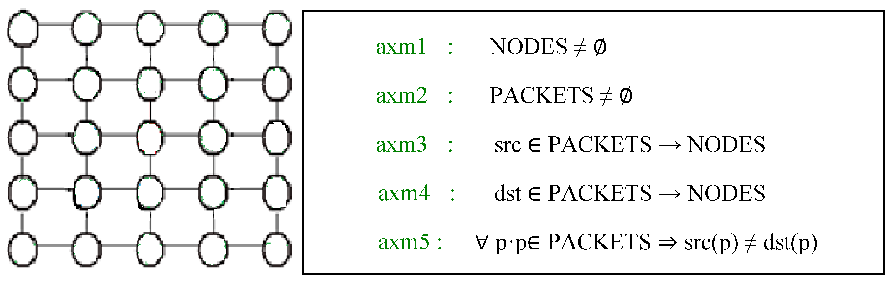
First refinement: We assume that the graph is given a set of nodes. Next, we define a set of colours (Red_Colour, Green_Colour, and Blue_Colour), whose components are the colours selected by the nodes during the execution of the algorithms of graph colouring. We specify some properties of these constants GRAPH, Green_Colour, Red_Colour and Blue_Colour as follows:
-
Axm5 axiom defines that all vertices belong to the GRAPH; they are not isolated.
-
Axm6 axiom defines that the graph is irreflexive.
Systems 05 00017 i003
-
Axm7 axiom expresses that the graph is symmetric.
-
Axm8 axiom expresses that the graph is connected.
In this refined level abstract of the machine, we will consider that all nodes can send and receive packets, thus allowing them to be coloured in green (see Figure 16).
The CCorrecteNode variable is defined with the following property:
inv1:ColouredCorrectNode‏∈ NODES ⇸ COLOUR
This property defines a node as a part of all coloured nodes. Therefore, the graph will be coloured green.
-
Second refinement: The question turns now about the red colour and we need to find an inductive property which simulates the calculation of this function. Two variables will be added at this level; FaultyNode and CFaultyNode which are defined with the following properties where the FaultyNode is a failed node and coloured in red (see Figure 17):
-
Third refinement: In this level, the calculation of the selection function of the active node (see Figure 18) is specified in a simple way to break the complexity of the role of this node:
Table 2 gives the number of proofs obligations for the colouring algorithms of nodes which are automatically discharged proving the checking of criteria for considered abstraction level and step by step. These obligation results show that current development focuses on Vertex colouring algorithms, especially that they include possible errors in the choice of colours by the nodes. Thus, as the number of faulty nodes is not accurate according to network size and specification step, we help to prove the logical sequence of events.

2.4.3. Formal Development of the Bypassing Routing

This section presents the proposed formal development of the fault tolerant routing scheme of the considered NoC architecture. This proven formalism is based on refinement, which allows breaking the operation complexity of the routing algorithm and performing this formalization with different levels of abstraction carried out step-by step. Figure 18 presents the step-by-step modelling of the proposed fault tolerant routing scheme (see Figure 19).
a. Abstract specification level: xyC00
The abstract level defines the role of the network to send an infinite number of messages which are packetized and encapsulate (Flitization) into sequence of packets from a source (s) to a destination (d) (see Figure 20).
A set of switches (NODES), a set of packets (PACKETS), a function src, associating packets (p) and their sources, a function dst, coupling packets (p) and their destinations, are defined in context xyC00. The machine xyM00 uses (sees) the contents of context xyC00, and describes an abstract view of the service provided by the NoC. An event SEND presents the sending of a packet (p), by its source (s), to a switch destination (d). An event RECEIVE depicts the receiving of a sent packet (p) by its destination (d).
The first model xyC00 is an abstract description, which specifies the packet nodes, sources (src), destinations (dst) of each packet (p). The following axioms describe how the source (src), and destination (dst) have been defined for a package (p). Each packet has a single source and single destination that are different:
axm3 : src ∈ PACKETS → NODES
axm4 : dst ∈ PACKETS → NODES
axm5 : ∀ p · p ∈ PACKETS ⇒ src(p) ≠ dst(p)
The machine xyM00 specifies the sending (sent) and receiving (rcvd) packets (p) in the abstract way. Thereby, the send is set to the action:
sent ≔ sent ∪ {s ↦ p}
The reception is set with the following action:
rcvd≔rcvd∪ {d ↦ p}
b. The first refinement: cutting packets on flits (Flitization)
The machine xyM01 refines xyM00 and introduces scutting packets on flits.
xyC01: FLITS is a new set introduced by this context by cutting each packet on flits (axm1), and the flits of each packet are different from those of other packets (axm2).
axm1 : flits ∈ PACKETS → ℙ1(FLITS)
axm2 : ∀ p1, p2 · p1 ∈ PACKETS ∧ p2 ∈ PACKETS ∧ p1 ≠ p2 ⇒ flits(p1) ∩ flits(p2) = ∅
xyM01: Instead of sending (act1) a whole package, this sends packet flits (see Figure 21) and can be received only when all the flits that were sent up (grd6);
The SEND_FLIT event is defined at this level by the action:
WHERE
  grd6 : f ∉ f_sent[{s}]
THEN
  act1 : f_sent ≔ f_sent ∪ {s ↦ f}
c. The second refinement: adding LocCopy variable
xyC02: The copy of the package in node (axm7) is in the original sources (axm8) and in the sources of these packages. Theorem (axm10) states that the local copy is originally in one place on the network.
axm7 : InitLocCopy ∈ NODES ↔ PACKETS
axm8 : ∀ p · p ∈ PACKETS ⇒ src(p) ↦ p ∈ InitLocCopy
axm9 : ∀ n, p · n ∈ NODES ∧ p ∈ PACKETS ∧ n ↦ p ∈ InitLocCopy ⇒ n = src(p)
axm10 : ∀ n1, n2, p · n1 ∈ NODES ∧ n2 ∈ NODES ∧ p ∈ PACKETS ∧ n1 ↦ p ∈InitLocCopy∧
 n2 ↦ p ∈InitLocCopy ⇒ n1 = n2
xyM02: In this machine, refinement adds RECEIVE_FLIT to indicate when we can get a package (view the context xyC01).
WHERE
 grd7 : flits(p) ⊆ f_sent[{s}]
THEN
 act1 : f_rcvd ≔ f_rcvd ∪ {d ↦ f}
d. Third refinement: Faulty node
xyM03: It is a refinement of the behaviour of a node if it is broken and/or when it returns to normal as expressed in both disable and enable events. This level also allows us to create the variable locCopy (see Figure 22, case (02)) to ensure flit sends of a packet without loss.
The following invariants are used to show how the model has been specified:
inv1 : gr ⊆ NODES × NODES
inv2 : str ∈ NODES ↔ FLITS
inv3 : ran(str) ⊆ ran(f_sent)
inv4 : ∀f· f ∉ ran (f_rcvd) ∧ f ∈ ran(f_sent) ⇒ f ∈ ran(str)
inv5 : locCopy ∈ NODES ↔ PACKETS
inv9 : gr = gr∼
inv10 : gr ⊆ g
The invariant inv1 expresses that graph (gr) is set of NODES related between them in the current network. In inv2, str is a variable which contains the current position of a flit in the network. inv3 is a flit circulating in the network was sent by a source. inv4 is a flit sent but not received and starved in the network. In inv5, locCopy is a packet in node. inv9 indicates that graph (gr) is symmetric while in inv10 graph gr is always an amendment contained in the original graph g. Those are important invariants which represented in our graph.
Disable: a node n becomes faulty/off. It can no longer receive or route messages of its neighbours. The new graph new_gr will be the current without bidirectional links between the node n and its neighbours (grd4). grd6 expresses that the new_gr is symmetric and not-empty (grd6), and the action updating of the current graph with the new graph.
WHERE
 grd1 : n ∈ NODES
 grd2 : n ∈dom(gr)
 grd3 : n ew_gr⊆ NODES × NODES
 grd4 : new_gr = gr ∖ (({n} × gr[{n}]) ∪ (gr[{n}] × {n}))
 grd5 : new_gr∼ = new_gr
 grd6 : new_gr ≠ ∅
THEN
 act1 : gr ≔new_gr
END
Enable: A node n becomes active. It can receive and route messages from its neighbours when n is no longer part of the current graph. It gives n in the current graph with bidirectional links with his former neighbours.
WHERE
 grd1 : n ∈ NODES
 grd2 : n ∉ dom(gr)
 grd3 : n ∈ dom(g)
THEN
 act1 : gr ≔ gr ∪ (({n}×g[{n}])∪(g[{n}]×{n}))
END
e. Fourth refinement:
xyC03: The environment has allowed us to break the xyC04 context to simplify the proof with the RODIN tool.
  • Extension of the definition of the initial graph by adding the concept of square graph. g is the initial graph in which all nodes are connected together since their coordinates (prj1(c), prj2(c)) are neighbours. This is a graph that is part of the eligible graphs.
    (∀ n1, n2, c1, c2 ·n1 ↦ c1 ∈posnd∧ n2 ↦ c2 ∈ posnd∧ n1 ≠ n2 ∧
     (
     (prj1(c1) = prj1(c2)−1 ∧ prj2(c1) = prj2(c2)) ∨
     (prj2(c1) = prj2(c2)−1 ∧ prj1(c1) = prj1(c2)) ∨
     (prj1(c1) = prj1(c2)+1 ∧ prj2(c1) = prj2(c2)) ∨
     (prj2(c1) = prj2(c2)+1 ∧ prj1(c1) = prj1(c2))
    )
    ⇒ n1 ↦ n2 ∈ g)
  • Let x be a node x with coordinates cx (posnd(x)). If there is another node with coordinates cd as the axis of the coordinate but which smaller then it can be moved on the x-axis to the left from x.
    ∀ x, cx · x ∈ NODES ∧ cx = posnd(x) ∧
    (∃ d, cd · d ∈ NODES ∧ cd = posnd(d) ∧ prj1(cx) > prj1(cd))
    (prj1(cx)−1 ↦ prj2(cx)) ∈ ran(posnd)
  • Let x be a node with coordinates cx. If there is a node with coordinates cd as the axis of the coordinate but which are larger than that of the x-axis, then it can be moved to the right from x.
    ∀ x, cx · x ∈ NODES ∧ cx = posnd(x) ∧
    (∃ d, cd · d ∈ NODES ∧ cd = posnd(d) ∧ prj1(cx) < prj1(cd))
    (prj1(cx)+1 ↦ prj2(cx)) ∈ ran(posnd)
  • g is an initial graph in which all nodes are interconnected in pairs of adjacent coordinates of x and y. This is a graph that is part of the eligible graphs.
    (∀ n1, n2, c1, c2 ·n1 ↦ c1 ∈posnd∧ n2 ↦ c2 ∈posnd∧ n1 ≠ n2 ∧ n1 ↦ n2 ∈ g
    ⇒ (
     (prj1(c1) = prj1(c2)−1 ∧ prj2(c1) = prj2(c2)) ∨
     (prj2(c1) = prj2(c2)−1 ∧ prj1(c1) = prj1(c2)) ∨
     (prj1(c1) = prj1(c2)+1 ∧ prj2(c1) = prj2(c2)) ∨
     (prj2(c1) = prj2(c2)+1 ∧ prj1(c1) = prj1(c2))
    )
     )
  • We give the “neighbours” (ind_nbg) diagonal “distance 1” node:
    ind_nbg ∈ NODES → ℙ(NODES)
  • If a node n is part of the faulty area and a node fails new_f_nodef_node, the set_of_f_nodes set is a direct neighbour or diagonal n. Thus, it is part of failing zone around new_f_node.
    ∀ n, r, nod, nd · n ↦ r ∈dom(zn) ∧ nod ∈ r ∧ nd∈ zn(n ↦ r) ∧ (nod ↦nd ∈ g ∨nd ∈ ind_nbg(nod)) ⇒ nod ∈ zn(n ↦ r)
  • Theorem: If a node fails f_nodeset_of_f_nodes, all nodes are direct neighbours or diagonal new_f_node. Then, it is part of the defective area new_f_node.
    ∀ n, r, nod · n ↦ r ∈ dom(zn) ∧ nod ∈ r ∧ (n ↦ nod ∈ g ∨ nod ∈ ind_nbg(n)) ⇒ nod ∈ zn(n ↦ r)
xyC04: Introduces the operators for calculating the active zone surrounding a node near a faulty zone. The step of the construction rectangular shape of an active zone za is as follows:
-
Xmin(b) contains the minimum X coordinate found in b:
∀ a, b · b ⊆ NODES ∧ b ≠ ∅∧ a ∈ b ⇒ (∃ c · c ∈ b ∧ prj1(posnd(c)) ≤ prj1(posnd(a)) ∧Xmin(b) = prj1(posnd(c)))
-
XMax(b) contains the maximum X coordinate found in b:
∀ a, b · b ⊆ NODES ∧ b ≠ ∅∧ a ∈ b ⇒ (∃ c · c ∈ b ∧ prj1(posnd(c)) ≥ prj1(posnd(a)) ∧Xmax(b) = prj1(posnd(c)))
-
Ymin(b) contains the minimum Y coordinate found in b:
∀ a, b · b ⊆ NODES ∧ b ≠ ∅∧ a ∈ b ⇒ (∃ c · c ∈ b ∧ prj2(posnd(c)) ≤ prj2(posnd(a)) ∧Ymin(b) = prj2(posnd(c)))
-
YMax(b) contains the maximum Y coordinate found in b:
∀ a, b · b ⊆ NODES ∧ b ≠ ∅∧ a ∈ b ⇒ (∃ c · c ∈ b ∧ prj2(posnd(c)) ≥ prj2(posnd(a)) ∧Ymax(b) = prj2(posnd(c)))
-
Lim Xmin(a) contains less than the X coordinate of the bounding rectangle and has Xmin(a) -1 within the graph g:
∀ a · a ⊆ NODES ∧ a ≠ ∅∧Xmin(a)−1 > 0 ⇒LimXmin(a) = Xmin(a)−1
-
Lim max (a) contains the coordinate of the upper X bounding rectangle and has Xmax (a) if one within the graph g:
∀ a · a⊆ NODES ∧ a ≠ ∅∧Xmax(a)+1 < nsize−1 ⇒LimXmax(a) = Xmax(a)+1
-
Lim Ymin (a) contains the Y coordinate of the bounding rectangle and has lower Xmin (a) -1 within the graph g:
∀ a · a ⊆ NODES ∧ a ≠ ∅ ∧ Ymin(a)−1 > 0 ⇒LimYmin(a) = Ymin(a)−1
-
Lim Ymax (a) contains the coordinate of upper rectangle encompassing a Y. Ymax (a) if one within the graph g:
∀ a · a ⊆ NODES ∧ a ≠ ∅ ∧ Ymax(a)+1 < nsize−1 ⇒LimYmax(a) = Ymax(a)+1
-
The rectangle given by za(a) and including a contains n nodes whose coordinates (x, y) are defined as:
LimXmin(a) ≤ x ≤ LimXmax(a) and LimYmin(a) ≤ y ≤ LimYmax(a)
axm24 : ∀ a · a ⊆ NODES ∧ a ≠ ∅
⇒za(a) = {nd∣ (prj1(posnd(nd)) ≥ LimXmin(a) ∧ prj1(posnd(nd)) ≤ LimXmax(a) ∧ prj2(posnd(nd)) ≥ LimYmin(a) ∧ prj2(posnd(nd)) ≤ LimYmax(a))}
We build the rectangle of the active area after forcing the evidence and limit the active node in NoC inside the network size limit. Thus, we add a rule to the firewall rule sets as follows:
Rules 5: The active zone has the option to occasionally disable unauthorized cases (see Figure 14b) for routing flits of a packet that has no possibility to arrive at the destination.
xyM04: This machine contains a refinement of two events:
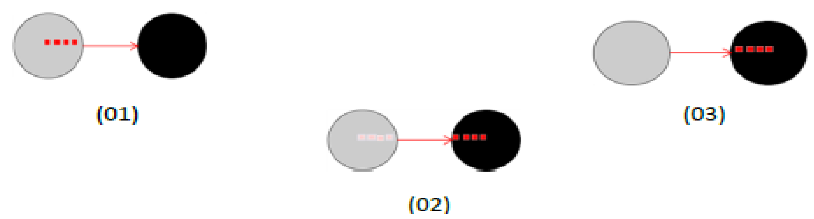
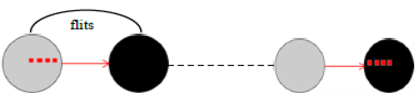
  • The routing flits in different directions depending on the destination. If after a node (s) is transmitted flit (f) to the node (y), (x) still has flits of (f), the local copy (LocCopy) does not change and x no longer has flits of (f). The local copy (LocCopy) of packet (p) changes from x to y. This is expressed in the following warning:
    flits(p) ⊈ (str[{y}] ∪ {f}) ⇒ newLocCopy = locCopy
    flits(p) ⊆ (str[{y}] ∪ {f}) ⇒ newLocCopy = (locCopy∖ {x ↦ p}) ∪ {y ↦ p}
    The cases of the XY routing algorithm are matched with refinements of event FORWARD:
    -
    Case 01: (FORWAD-W) It forwards a flit (f) of a pack (P) to a neighbouring node (y) located W. This event is raised if x-coordinated destination (d) (the flit (f)) is inferior to x-coordinated the current node (s).
    -
    Case 02: (FORWARD-E) It forwards a flit (f) of a pack (P) to a neighbouring node (y) located E. This event is raised if x-coordinated destination (d) (the flit (f)) is superior to x-ordinated the current node (s).
    -
    Case 03: (FORWARD-N) It forwards a flit (f) of a pack (P) to a neighbouring node (y) located in N. This event is triggered if y-coordinated destinations (d) (the flit (f)) is superior to y-coordinated current (x) and x-coordinated the destination node (d) is equal to x-ordinated the current node (s), or if conflicts cannot pass along the x-axis.
    -
    Case 04: (FORWARD-S) It forwards a flit (f) of a pack (P) to a neighbouring node (y) situated S. This event is triggered if y-coordinated destination (d) (the flit (f)) is less than y-coordinated to the current (x) and x-ordinated the destination node (d) is equal to x-ordinated the current node (s), or if conflicts cannot pass along the x-axis.
  • The delivery of a flit (f) of the packet (p) from the node (s) in an active zone.
-
FORWARD_AUTH1: Can forward a flit (f) a packet (p) to a neighbouring node (y) to the east of the current node (x) knowing that the source node (b) in the south compared to the current node (x) and headed to a destination (d) to the east. With RODIN, this case is expressed as follows:
grd14 : b ∈ NODES
grd15 : d ∈ NODES
grd16 : x ≠ d
grd17 : x ∈ z_a
grd18 : prj1(posnd(x))< prj1(posnd(d))
grd19 : prj2(posnd(y)) = prj2(posnd(x))
grd20 : prj1(posnd(y)) = prj1(posnd(x))+1
grd21 : prj2(posnd(b))< prj2(posnd(x))
grd22 : prj1(posnd(x)) = prj1(posnd(b))
grd23 : b=src(p)
-
FORWARD_AUTH2: Can forward a flit (f) and a packet (p) to a neighbouring node (y) to the right of the current (x) node knowing the source node (b) to the West relative to the current node (x) and headed to a destination (d) to the east. With RODIN, this case is expressed as as follows:
grd20 : prj1(posnd(y)) = prj1(posnd(x))+1
grd21 : prj2(posnd(b))= prj2(posnd(x))
grd22 : prj1(posnd(b)) = prj1(posnd(x)) -1
-
FORWARD_AUTH3: Can forward a flit (f) and a packet (p) to a neighbouring node (y) to the West of the current (x) node knowing the source node (b) is located in relation to node current (x) and headed to a destination (d) to the west. With RODIN, this case is expressed as follows:
grd18 : prj1(posnd(x))> prj1(posnd(d))
grd19 : prj2(posnd(y)) = prj2(posnd(x))
grd20 : prj1(posnd(y)) = prj1(posnd(x))-1
grd21 : prj2(posnd(b))= prj2(posnd(x))
grd22 : prj1(posnd(b)) = prj1(posnd(x)) +1
-
FORWARD_AUTH4: Can forward a flit (f) and a packet (p) to a neighbouring node (y) to the West of the current (x) node knowing the source node (b) to the east from the node current (x) and headed to a destination (d) to the west. With RODIN, this case is expressed as follows:
grd18 : prj1(posnd(x))> prj1(posnd(d))
grd19 : prj2(posnd(y)) = prj2(posnd(x))
grd20 : prj1(posnd(y)) = prj1(posnd(x))-1
grd21 : prj2(posnd(b))> prj2(posnd(x))
grd22 : prj1(posnd(b)) = prj1(posnd(x))
Table 3 gives the number of proofs obligations for the refinements development of the bypassing routing which are automatically discharged proving the checking of criteria for each considered levels of abstraction and step by step. The proposed incremental formal verification of a fault tolerant routing scheme of the NoC-switch strategy has been performed using RODIN environment. The number of proof obligations measures the complexity of the development that are automatically/manually discharged. Note that, in the case of M03 Machine, there is more evidence than interactive machines, which explains that the goal was simplified (semi-automatic). By cons in the context C03, we needed more assumptions in order to find more evidence that a automatically discharged.

3. Discussion

We have given a formal verification of a bypassing routing algorithm for the design of reliable NoC by using the Event-B methodology. The main originality of the proposed routing algorithm based on the bypass rules is that the routing is performed in the activated area depending on the number of faulty nodes or regions where, in the case of a rectangular region (or a group of faults forming a rectangular shape), the activated nodes form a ring around the region and the routing in activated area is reduced to route along the formed ring. Therefore, a formal proof on the bypassing operations inside NoC and the dependability problems are related to the choice of path routing of data packets and strategies imposed for diversion in the case of detected faulty routers. The formalization process is based on an incremental and validated correct-by-construction development of the adaptive NoC architecture. We have considered the event B refinement as stepwise validation. Indeed, the Event B modelling language can express safety properties, which are invariants, theorems or safety properties in a machine corresponding to the system. Thereby, Event B allows a progressive development of models through refinements by considering two main structures available in Event B which are Contexts expressing static information about the model and Machines expressing dynamic information about the model, invariants, safety properties, and events. The mere usage/running of provers (provided by the RODIN platform) allowed us to discharge these obligations (see Table 2 and Table 3). These proof operators can be used to improve the NoC architecture specified using Event-B models through refined models while to get out all the bugs during the creation of hardware architecture which cannot found with simulations or analytic methods. Indeed, contrary to verification by simulation only, our work provides a framework for developing the Network-on-Chip Architecture based XY algorithm. Thus, this demonstration is comprehensive in order to detect problems even for configurations that designers have not yet considered. The purpose is to develop a dependable routing algorithm using essential safety properties together with a formal proof that asserts its correctness. This will allow proving the functionality of the associated hardware architecture by replacing the time consuming simulations in the design flow by a formal proof method.

4. Conclusions and Future Work

In this paper, we have proposed a formal method using Event-B to specify, verify and prove the behaviour of fault tolerant routing scheme suitable for design reliable or adaptive NoC architectures. More precisely, we have considered the correct-by-construction paradigm for specifying the behaviour hardware systems. The correct-by-construction paradigm offers an alternative approach to prove and derive correct systems and architectures, through the reconstruction of a target system using stepwise refinement and validated methodological techniques. Our goal is to complement the time consuming simulations in the design flow with a formal proof method. This formal verification [28] can either compare the computer data that will enable the realization of a future NoC Switch with its specification, or verify that the circuit obeys certain constraints characterizing its proper functioning. The novelty of our proposed design approach for the NoC routing associated with error detectors is that it can prove the dependability of the routing of the data packets to get around the faulty switches or regions (zone bypass decision) which is adapted for the design of fault tolerant NoCs. We have formalized and proven that our proposed algorithm allows the routing of packets in the networks incorporating faulty nodes and regions. Our approach relies on an incremental development of routing operations of the Network-on-Chip Architecture, using the Event B formalism. The formalization of the architecture is presented from an abstract level to a more concrete level in a hierarchical way. We have proved our incremental formal verification of our proposed fault tolerant routing scheme of the NoC witch strategy with environmental RODIN, where the number of proof obligations measures the complexity of the development, which have been automatically/manually discharged. This approach will develop the general process of modelling with Event-B which makes the notion of refinement intuitive.
A framework for developing NoC Architectures and the XY routing algorithm using essential safety properties together with a formal proof that asserts its correctness has been developed. As a part of our future efforts, we have considered the translation of the most concrete (detailed and close to algorithmic form) model into an intermediate language, from which hardware description (e.g., in VHDL) can be extracted. Moreover, it is noted that the first levels of the Event-B design of the NoC Architecture express general cases of routing methodologies and fall in the interesting domain of reusable and generic refinement based structures. We plan to investigate further this domain of generic and reusable proof-based models.

Author Contributions

Hayat Daoud and Mikael Heil performed the experiments and have contributed to wrote the paper. Camel Tanougast conceived the experiments and wrote the paper. Mostefa Belarbi analyzed the results. Camille Diou contributed to the analysis of RODIN tool and the NoC architecure as well as to wrote the paper.

Conflicts of Interest

The authors declare no conflict of interest.

References

  1. Killian, C.; Tanougast, C.; Monteiro, F.; Dandache, A. Smart Reliable Network-on-Chip. IEEE Trans. Very Large Scale Integr. Syst. 2014, 22, 242–255. [Google Scholar] [CrossRef]
  2. Leonidas, T.; Sere, K.; Plosila, J. Modeling Communication in Multi–Processor Systems–on–Chip Using Modular Connectors. Innovations in Embedded and Real-Time Systems Engineering for Communication. IGI Glob. 2012, 219–240. [Google Scholar] [CrossRef]
  3. Guang, L.; Plosila, J.; Isoaho, J.; Tenhunen, H. Hierarchical Agent Monitored Parallel On-Chip System: A Novel Design Paradigm and Its Formal Specification. In Innovations in Embedded and Real-Time Systems Engineering for Communication; IGI Publishing: Hershey, PA, USA, 2010; pp. 86–105. [Google Scholar]
  4. Ostroumov, S.; Tsiopoulos, L.; Plosila, J.; Sere, K. Formal approach to agent-based dynamic reconfiguration in Networks-On-Chip. J. Syst. Archit. 2013, 59, 709–728. [Google Scholar] [CrossRef]
  5. Verbeek, F.; Schmaltz, J. Easy Formal Specification and Validation of Unbounded Networks-on-Chips Architectures. ACM Trans. Design Autom. Electron. Syst. 2012, 17. [Google Scholar] [CrossRef]
  6. Borrione, D.; Helmy, A.; Pierre, L.; Schmaltz, J. A Formal Approach to the Verification of Networks on Chip. EURASIP J. Embed. Syst. 2009, 2009, 548324. [Google Scholar] [CrossRef]
  7. Aydi, Y.; Tligue, R.; Elleuch, M.; Abid, M.; Dekeyser, J. A Multi Level Functional Verification of Multistage Interconnection Network for MPSOC. In Proceedings of the 16th IEEE International Conference on Electronics, Circuits, and Systems, Yasmine Hammamet, Tunisia, 13–16 December 2009; pp. 439–442. [CrossRef]
  8. Van den Broek, T.; Schmaltz, J. Towards A Formally Verified Network-on-Chip. In Proceedings of the 2009 Formal Methods in Computer-Aided Design, (FMCAD 2009), Austin, TX, USA, 15–18 November 2009; pp. 184–187.
  9. Schmaltz, J.; Borrione, D. A functional formalization of on chip communications. Form. Asp. Comput. 2008, 20, 241–258. [Google Scholar] [CrossRef]
  10. Voros, J.; Snook, C.; Hallerstede, S.; Masselos, K. Embedded System Design Using Formal Model Refinement: An Approach Based on the Combined Use of UML and the B Language. Design Autom. Embed. Syst. 2004, 9, 67–99. [Google Scholar] [CrossRef]
  11. Laibinis, L.; Troubitsyna, E.; Leppänen, S. Service-Oriented Development of Fault Tolerant Communicating Systems: Refinement Approach. Int. J. Embed. Real-Time Commun. Syst. 2010, 1, 61–85. [Google Scholar] [CrossRef]
  12. Verbeek, F.; Schmaltz, J. Formal Specification of Networks-on-Chips:Deadlock and Evacuation. In Proceedings of the Design, Automation Test Europe Conference & Exhibition, Dresden, Germany, 8–12 March 2010; pp. 1701–1706.
  13. Helmy, A.; Pierre, L.; Jantsch, A. Theorem Proving Techniques for the Formal Verification of NoC Communications with Non-minimal Adaptive Routing. In Proceedings of the IEEE 13th International Symposium on Design and Diagnostics of Electronic Circuits and Systems, Vienna, Austria, 14–16 April 2010; pp. 221–224.
  14. Yang, S.-A.; Baras, J.S. Correctness Proof for a Dynamic Adaptive Routing Algorithm for Mobile Ad-hoc Networks. In IFAC Workshop—Modeling and Analysis of Logic Controlled Dynamic Systems; Elsevier: New York, NY, USA, 2003; pp. 1–10. [Google Scholar]
  15. Wu, J. A fault-tolerant and deadlock-free routing protocol in 2D meshes based on odd-even turn model. IEEE Trans. Comput. 2003, 52, 1154–1169. [Google Scholar]
  16. Park, D.; Nicopoulos, C.; Kim, J.; Vijaykrishnan, N.; Das, C. Exploring fault-tolerant network-on-chip architectures. In Proceedings of the International Conference on Dependable Systems and Networks (DSN 2006), Philadelphia, PA, USA, 25–28 June 2006; pp. 93–104.
  17. Cansell, D.; Tanougast, C.; Beviller, Y. Integration of the proof process in the design of microelectronic architecture for bitrate measurement instrumentation of transport stream program MPEG-2 DVB-T. In Proceedings of the IEEE International Workshop on Rapid System Prototyping, Geneva, Switzerland, 28–30 June 2004; pp. 157–163.
  18. Leavens, G.T.; Abrial, J.-R.; Batory, D.S.; Butler, M.J.; Coglio, A.; Fisler, K.; Hehner, E.C.R.; Jones, C.B.; Miller, D.; Jones, S.L.P.; et al. Roadmap for enhanced languages and methods to aid verification. In Proceedings of the 5th International Conference on Generative Programming and Component Engineering, Portland, OR, USA, 22–26 October 2006; Jarzabek, S., Schmidt, D.C., Veldhuizen, T.L., Eds.; ACM: New York, NY, USA, 2006; pp. 221–236. [Google Scholar]
  19. Abrial, J.-R.; Cansell, D.; Mery, D. A mechanically proved and incremental development of IEEE 1394 tree identify protocol. Form. Asp. Comput. 2003, 14, 215–227. [Google Scholar] [CrossRef]
  20. Clarke, E.M.; Grumberg, O.; Jha, S. Verifying parameterzed networks. ACM Trans. Program. Lang. Syst. 1997, 19, 726–750. [Google Scholar] [CrossRef]
  21. Bharadwaj, R.; Felty, A.; Stomp, F. Formalizing Inductive Proofs of Network Algorithms. In Proceedings of the 1995 Asian Computing Science Conference, Springer-Verlag, London, UK, 11–13 December 1995.
  22. Curzon, P. Experiences formally verifying a network component. In Proceedings of the IEEE Conference on Computer Assurance, Gaithersburg, MD, USA, 27 June–1 July 1994.
  23. Gordon, M.; Melham, T. Introduction to HOL: A Theorem Proving Environment for Higher Order Logic; Cambridge University Press: Cambridge, UK, 1993. [Google Scholar]
  24. Chenard, J.S.; Bourduas, S.; Azuelos, N.; Boul’e, M.; Zilic, Z. Hardware Assertion Checkers in On-line Detection of Network-on-Chip Faults. In Proceedings of the Desig Automation and Test in Europe, Worshop on Diagnostic Services in Networks-on-Chips, Nice, France, 16–20 April 2007.
  25. IEEE. IEEE Standard for Property Specification Language (PSL). IEEE STD 1850. Available online: http://ieeexplore.ieee.org/document/1524461/ (accessed on 20 February 2017).
  26. Boule, M.; Zilic, Z. Automata-based assertion-checker synthesis of PSL properties. ACM Trans. Des Autom. Electron. Syst. 2008, 13, 1–21. [Google Scholar] [CrossRef]
  27. Clarke, E.M., Jr.; Grumberg, O.; Peled, D.A. Model Cheking; The MIT Press: Cambridge, MA, USA; London, UK, 1999; p. 6. [Google Scholar]
  28. Ogras, U.; Hu, J.; Marculescu, R. Key Research Problems in NoC Design: A Holistic Perspective. In Proceedings of the International Conference on Hardware/Software Codesign and System Synthesis (CODES+ISSS′2005), New York, NY, USA, 18–21 September 2005; pp. 69–74.
  29. Goossens, K. Formal Methods for Networks on Chips. In Proceedings of the Fifth International Conference on Application of Concurrency to System Design (ACSD′05), Saint Malo, France, 7–9 June 2005; IEEE Computer Society: Washington, DC, USA, 2005; pp. 188–189. [Google Scholar]
  30. Pande, P.; De Micheli, G.; Grecu, C.; Ivanov, A.; Saleh, R. Design, Synthesis, and Test of Networks on Chips. IEEE Design Test Comput. 2005, 22, 404–413. [Google Scholar] [CrossRef]
  31. Bjerregaard, T.; Mahadevan, S. A survey of research and practices of Network-on-chip. ACM Comput. Surv. 2006, 38, 1–51. [Google Scholar] [CrossRef]
  32. Jantsch, A. Models of Computation for Networks on Chip. In Proceedings of the Sixth International Conference on Application of Concurrency to System Design (ACSD′06), Turku, Finland, 28–30 June 2006; IEEE Computer Society: Washington, DC, USA, 2006; pp. 165–178. [Google Scholar]
  33. Nielsen, S.F.; Sparso, J. Analysis of low-power SoC interconnection networks. In Proceedings of the IEEE 19th Norchip Conference, Kista, Sweden, 12–13 November 2001; pp. 77–86.
  34. Grecu, C.; Ivanov, A.; Saleh, R.; Sogomonyan, E.; Pande, P. On-line Fault Detection and Location for NoC Interconnects. In Proceedings of the International On-Line Testing Symposium (IOLTS′06), Lake of Como, Italy, 10–12 July 2006; pp. 1–8.
  35. Murali, S.; De Micheli, G.; Benini, L.; Theocharides, T.; Vijaykrishnan, N.; Irwin, M.J. Analysis of Error Recovery Schemes for Networks on Chips. IEEE Design Test Comput. 2005, 22, 434–442. [Google Scholar] [CrossRef]
  36. Schafer, M.; Hollstein, T.; Zimmer, H.; Glesner, M. Deadlock-free routing and Component placement for irregular mesh-based networks-on-chip. In Proceedings of the 2005 IEEE/ACM International Conference on Computer-Aided Design (ICCAD′05), San Jose, CA, USA, 6–10 November 2005; IEEE Computer Society: Washington, DC, USA, 2005; pp. 238–245. [Google Scholar]
  37. Gebremichael, B.; Vaandrager, F.W.; Zhang, M.; Goossens, K.; Rijpkema, E.; Radulescu, A. Deadlock Prevention in the Æthereal protocol. In Proceedings of the 13th IFIP WG 10.5 Advanced Research Working Conference on Correct Hardware Design and Verification Methods (CHARME′05), Saarbrücken, Germany, 3–6 October 2005.
  38. Bendisposto, J.; Leuschel, M.; Ligot, O.; Samia, M. La validation de modèles Event-B avec le plug-in ProB pour RODIN. TSI 2008, 27, 1065–1084. [Google Scholar] [CrossRef]
  39. Sayar, I.; Bhiri, M.-T. From an abstract specification in event-B toward an UML/OCL model. In Proceedings of the 2nd FME Workshop on Formal Methods in Software Engineering (FormaliSE 2014), Hyderabad, India, 3 June 2014; pp. 17–23.
  40. Jastram, M. (Ed.) RODIN User’s Handbook. Sponsored by the Deploy Project. 2012. Available online: https://www3.hhu.de/stups/handbook/rodin/current/pdf/rodin-doc.pdf (accessed on 20 February 2017).
  41. Andriamiarina, M.B.; Daoud, H.; Belarbi, M.; Méry, D.; Tanougast, C. Formal verification of fault tolerant NoC-based architecture. In Proceedings of the First International Workshop on Mathematics and Computer Science (IWMCS 2012), Tiaret, Algeria, 16–17 December 2012.
  42. Métivier, Y.; Robson, J.M.; Saheb-Djahromi, N.; Zemmari, A. Brief Annoucement: Analysis of an Optimal Bit Complexity Randomised Distributed Vertex Colouring Algorithm (Extended Abstract). In Proceedings of 13th International Conference on Principles of Distributed Systems (OPODIS 2009), Nîmes, France, 15–18 December 2009; pp. 359–364.
  43. Duffy, K.; O’Connell, N.; Sapozhnikov, A. Complexity analysis of a decentralised graph colouring algorithm. Inf. Process. Lett. 2008, 107, 60–63. [Google Scholar] [CrossRef]
  44. Nickerson, B.R. Graph colouring register allocation for processors with multi-register operands. In Proceedings of the ACM SIGPLAN 1990 Conference on Programming Language Design and Implementation (PLDI′90), White Plains, NY, USA, 20–22 June 1990; ACM: New York, NY, USA; pp. 40–52.
  45. Schneider, J.; Wattenhofer, R. Anew technique for distributed symmetry breaking. In Proceedings of the 29th ACM SIGACT-SIGOPS Symposium on Principles of Distributed Computing (PODC′10), Zurich, Switzerland, 25–28 July 2010; ACM: New York, NY, USA; pp. 257–266.
  46. Malkawi, M.; Hassan, M.A.-H.; Hassan, O.A.-H. Anew exam scheduling algorithm using graph coloring. Int. Arab J. Inf. Technol. 2008, 5, 80–86. [Google Scholar]
Figure 1. Illustration of machine and context relationships.
Systems 05 00017 g001
Figure 2. (a) Mesh topology; and (b) general structure of the QNoC switch architecture.
Systems 05 00017 g002
Figure 3. Format of a packet used in NoC.
Systems 05 00017 g003
Figure 4. Step-by-step Modelling of NoC Architecture.
Systems 05 00017 g004
Figure 5. Abstraction Level.
Systems 05 00017 g005
Figure 6. Adding Network.
Systems 05 00017 g006
Figure 7. Transfer of a Packet (p) between Switches.
Systems 05 00017 g007
Figure 8. Channel Introduction.
Systems 05 00017 g008
Figure 9. Adding Output Ports.
Systems 05 00017 g009
Figure 10. Adding Input Ports.
Systems 05 00017 g010
Figure 11. A regular Mesh with 2D-coordinates.
Systems 05 00017 g011
Figure 12. Switches: Structure and Links.
Systems 05 00017 g012
Figure 13. Example of an activated area.
Systems 05 00017 g013
Figure 14. Authorized (a); and Prohibited (b) turns and directions in activated nodes.
Systems 05 00017 g014
Figure 15. Abstract level.
Systems 05 00017 g015
Figure 16. Colouring of correct nodes in the NoC with green.
Systems 05 00017 g016
Figure 17. Colouring of Faulty node in the NoC with red.
Systems 05 00017 g017
Figure 18. Colouring of active node in the NoC with blue.
Systems 05 00017 g018
Figure 19. Step-by-step Modelling of fault tolerant routing algorithm suitable for NoC.
Systems 05 00017 g019
Figure 20. Abstract level.
Systems 05 00017 g020
Figure 21. Sends a packet as flits.
Systems 05 00017 g021
Figure 22. Routing flits keeping the local copy.
Systems 05 00017 g022
Table 1. Summary of proof obligations and discharged obligations.
ModelTotalAutoInteractive
xyC033100%00%
xyC166100%00%
xyC1200100%00%
xyC1300100%00%
xyC1411100%00%
xyC15500%5100%
xyM0262596.15%13.85%
xyM1382873.68%1026.32%
xyM12724562.5%2737.5%
xyM13743750%3750%
xyM14672334.33%4465.67%
xyM15241458.33%1041.67%
xyM16261869.23%830.77%
Total34220058.48%14241.52%
Table 2. The proof obligations for the colouring algorithm of nodes.
Element NameTotalAutoManuelReviewedUndischarged
ColourActiveZone2725200
Test C0011000
Test C0100000
Test M001614200
Test M0133000
Test M0233000
Test M0344000
Table 3. Results of proof obligations for the bypassing routing models.
Element NameTotalAutoManuelReviewedUndischarged
ActiveZone2725200
xyC0011000
xyC0100000
xyC021614200
xyC0333000
xyC0433000
xyM0000000
xyM0100000
xyM02139400
xyM034133800
xyM0422101200

