
Extending the Performance of Hybrid NoCs beyond the Limitations of Network Heterogeneity


Abstract
:1. Introduction
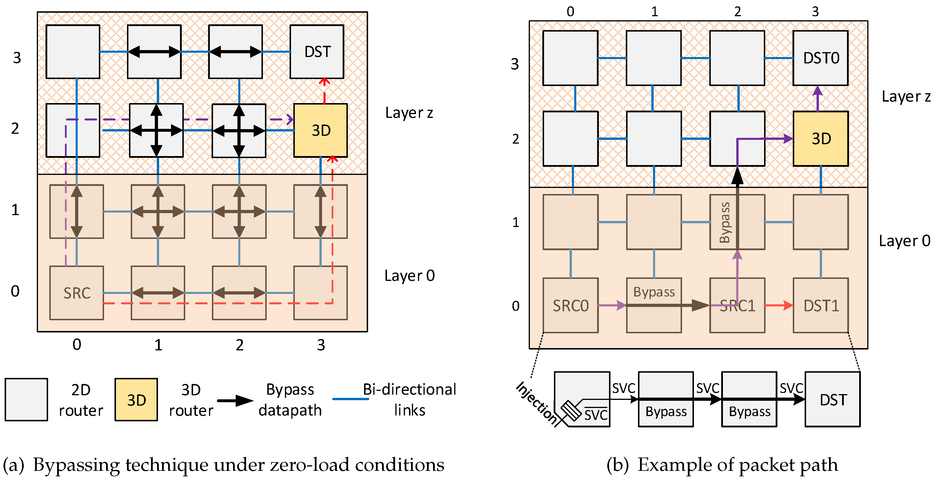
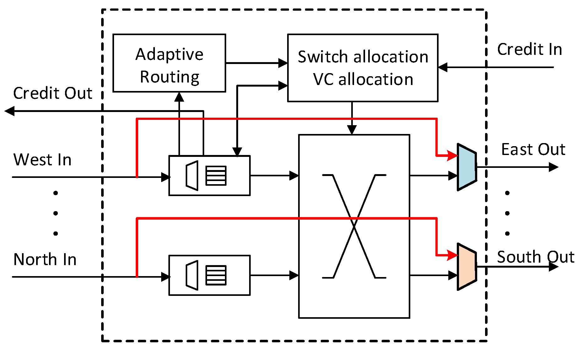
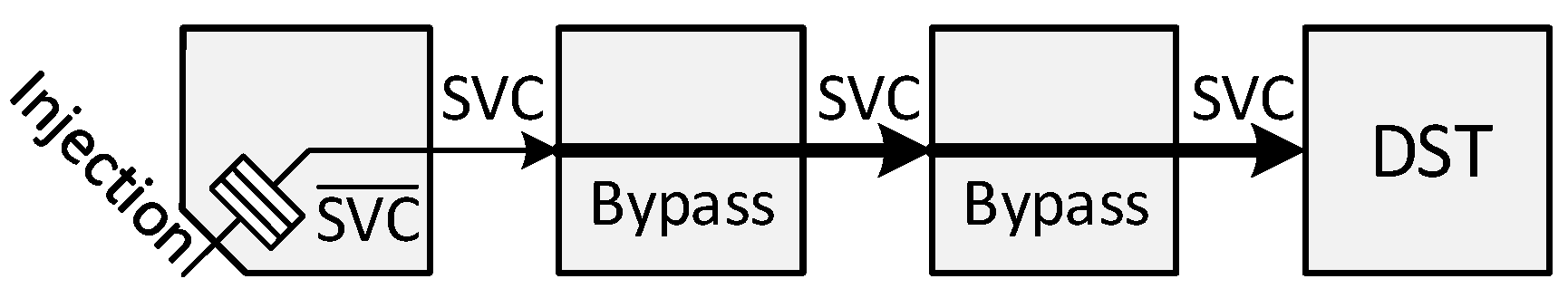
- We propose a low-complexity single-cycle bypassing mechanism for adaptive routers without using sideband lookahead signals. The bypass datapath applies DoR on packets to exploit the pre-setup intra-dimension crossbar connections. Consequently, bypass paths help escape the long adaptive routing pipeline and effectively reduce packet delay at low loads. By introducing a dedicated VC in the router’s micro-architecture, the path delay for bypassing logic implemented in the 45-nm standard cell library was reduced by .
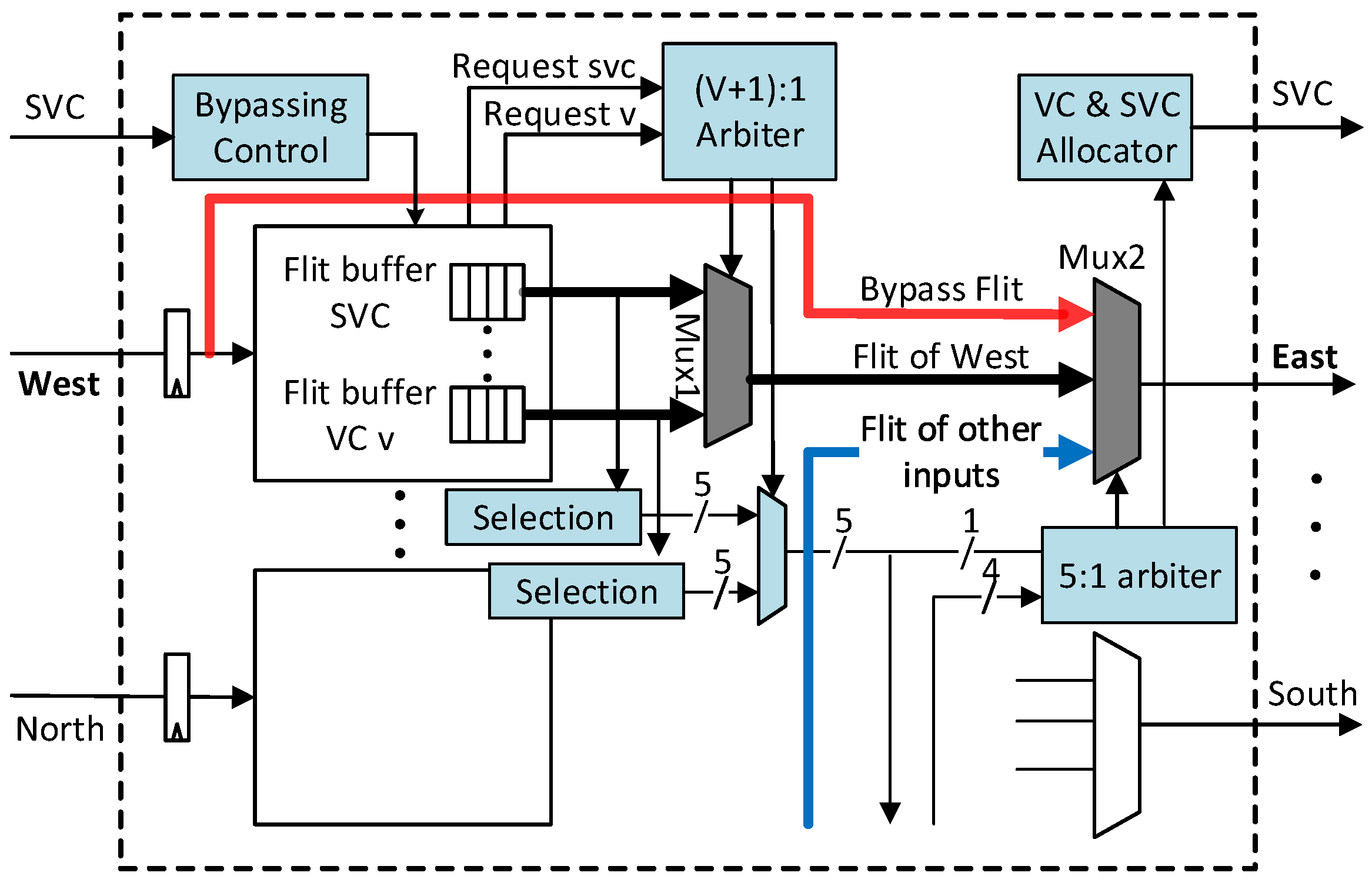
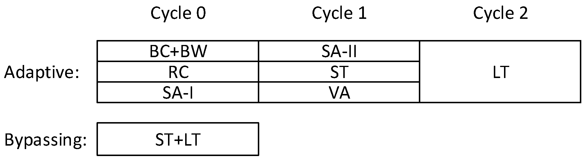
- We present a three-stage non-speculative high-throughput adaptive router that supports the proposed bypassing mechanism. By employing a tagging mechanism, the proposed router is able to either avoid congested nodes under high traffic conditions or employ the single-stage bypassing technique under low traffic conditions.
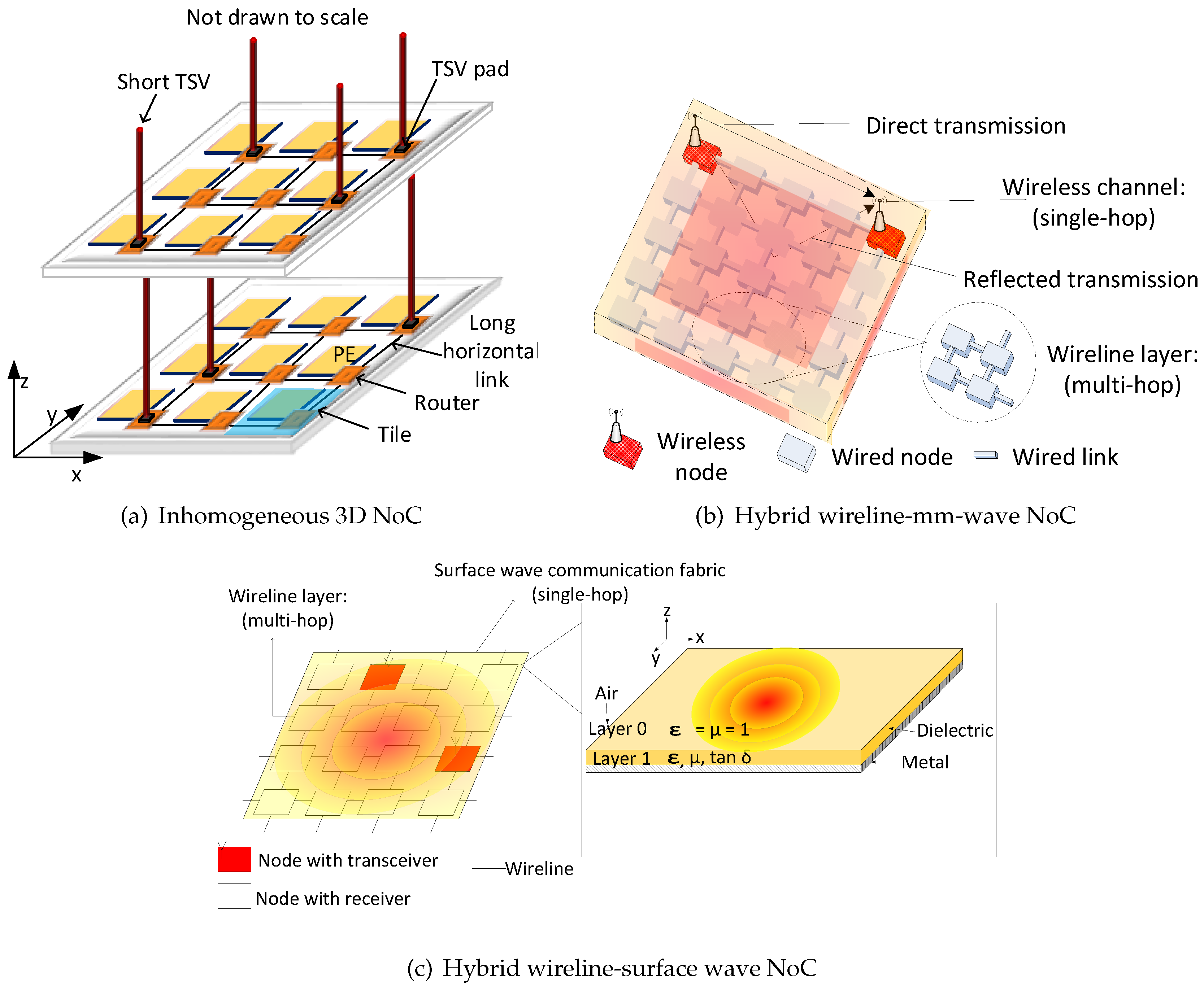
- We extend the performance of three promising communication fabrics for NoCs: low-cost 3D NoCs, mm-wave WiNoCs and surface wave WiNoCs. We replaced the slow 2D routers in inhomogeneous 3D NoCs (or multi-hop wired nodes in WiNoCs) with the proposed router to provide fast transfer between remote nodes and high performance nodes (3D routers or wireless routers).
- We perform cycle-accurate-based evaluations of the proposed router in high performance communication fabrics for NoCs and compare with emerging 3D NoCs, WiNoCs, as well as conventional low area wireline communication fabric. Even without any additional router port (as in the case of the SmallWorld network) or complex micro-architecture, the proposed router can reduce applications’ execution time of existing router architectures by an average of .
2. Related Work
2.1. NoC Router Architecture and Algorithms
2.2. 3D Network-on-Chip
2.3. Millimetre-Wave vs. Surface Wave-Enabled WiNoCs
3. On the Performance Improvement of Hybrid NoCs
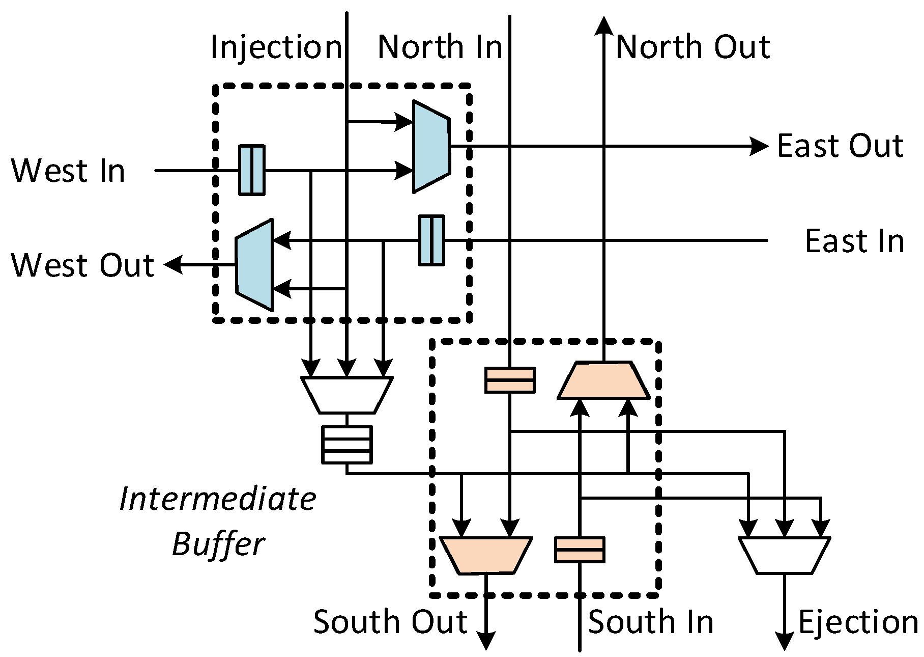
3.1. Intra-Dimension Bypassing
3.1.1. Bypass Datapath
3.1.2. Dedicated Virtual Channel for Bypassing
bypassing <= (dst.x != current.x) &
      vc_idle[o][vc]
if (svc) begin
 bypassing <= (dst.x != current.x) &
       svc_idle[o]
end
3.1.3. SVC Tagging Mechanism
- The SVC tag of the output port is not assigned to any packet.
- The SVC buffer at the corresponding downstream routeris empty.
3.2. Adaptive Routing
3.2.1. Router Pipeline
3.2.2. Virtual Channel Allocation
3.2.3. Deadlock Avoidance
4. Evaluation
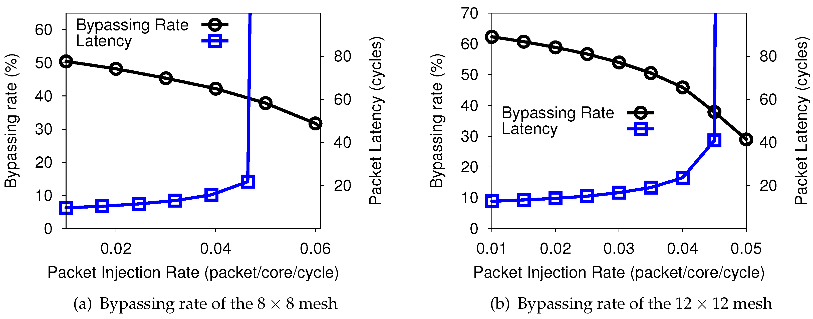
4.1. Bypassing Rate
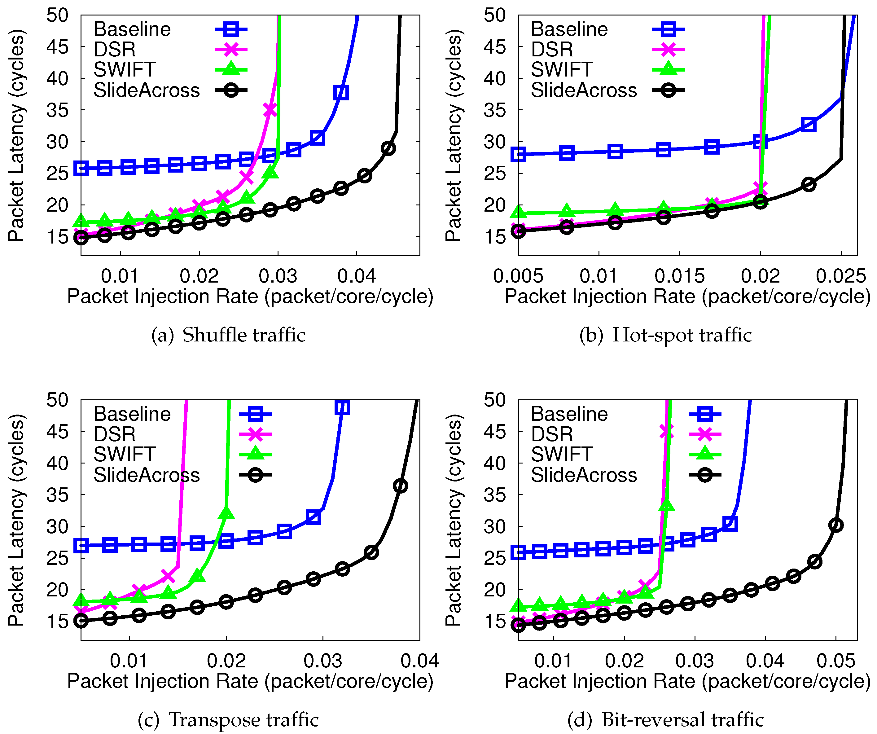
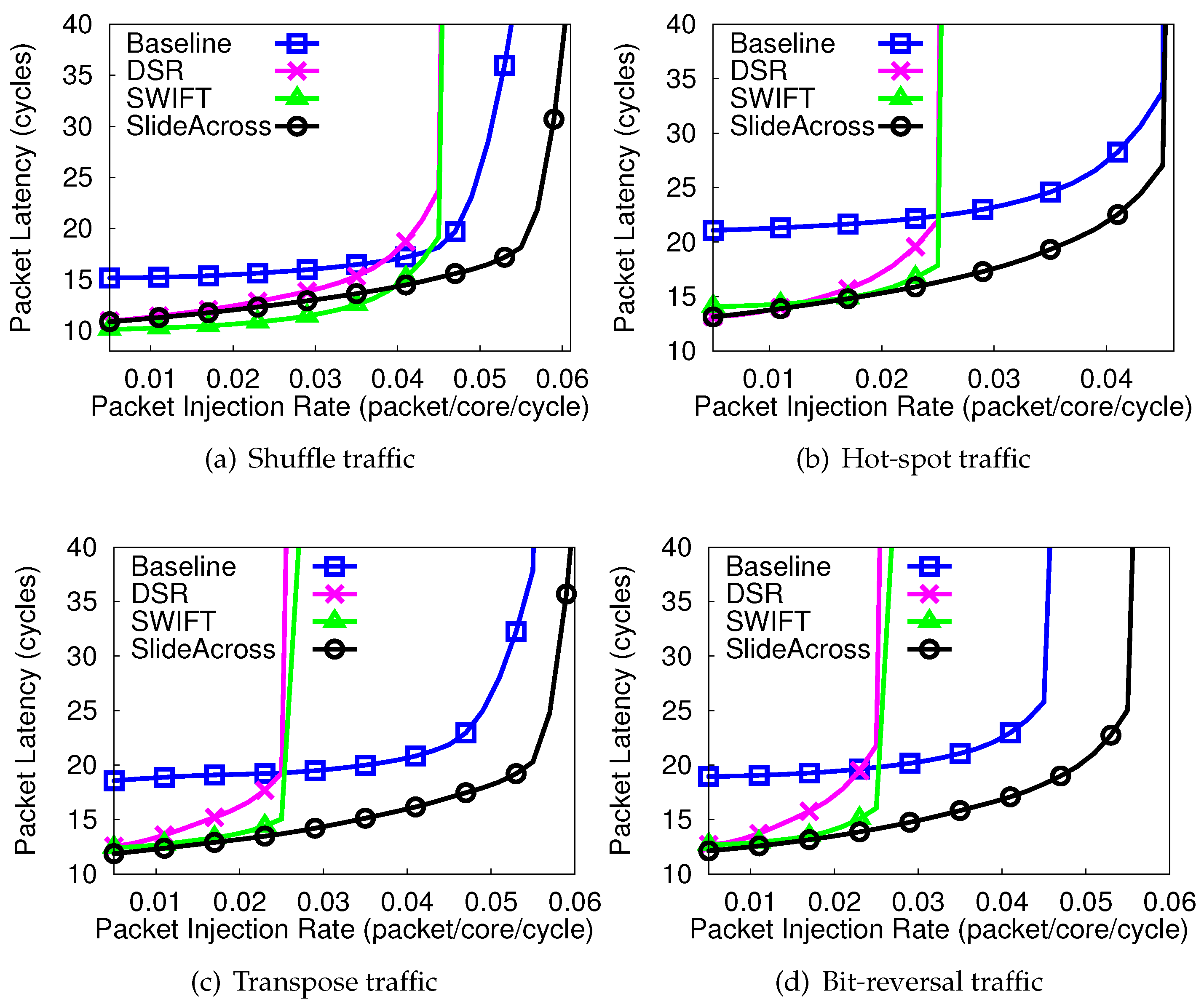
4.2. Packet Delay of Synthetic Traffic
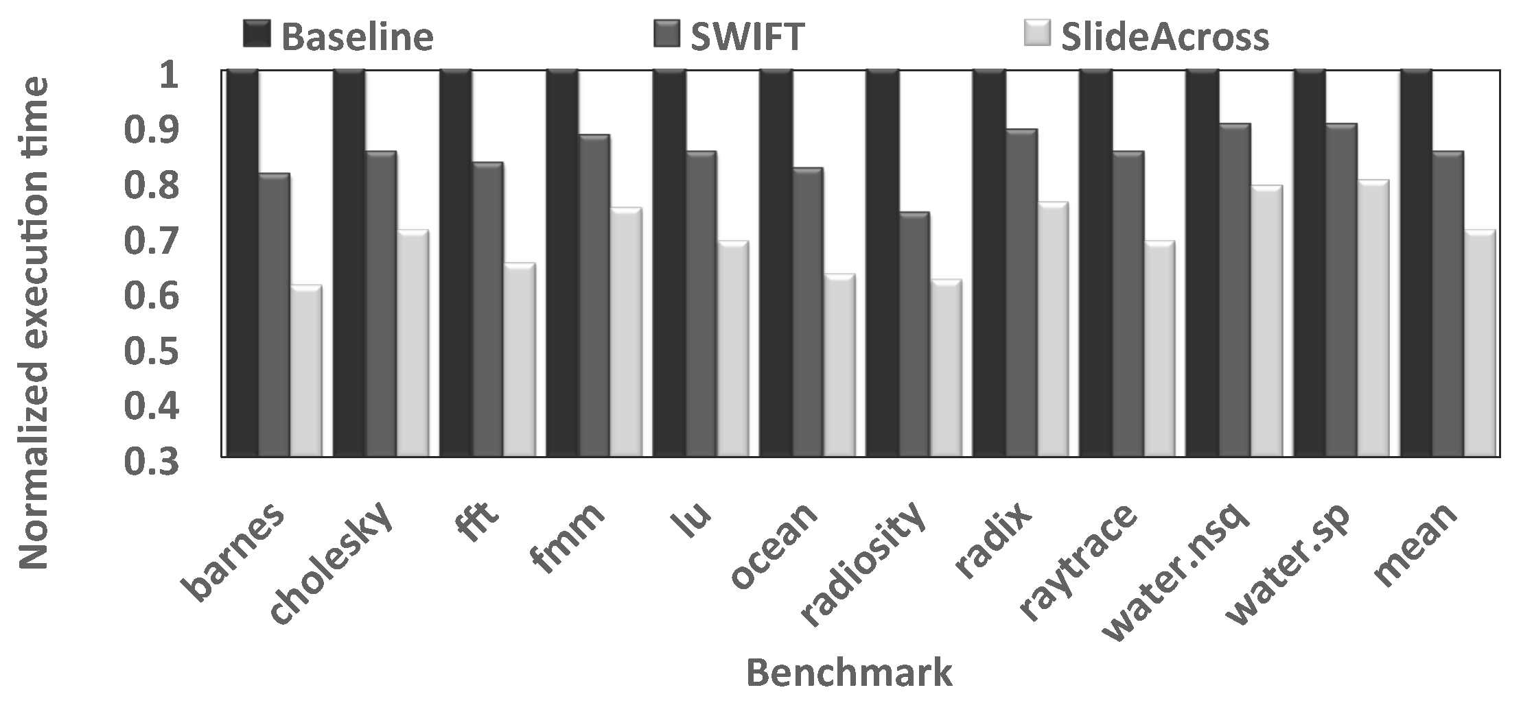
4.3. Application Execution Time
4.4. Area and Power Analysis
4.5. Impact of the Proposed Router on Inhomogeneous 3D NoCs
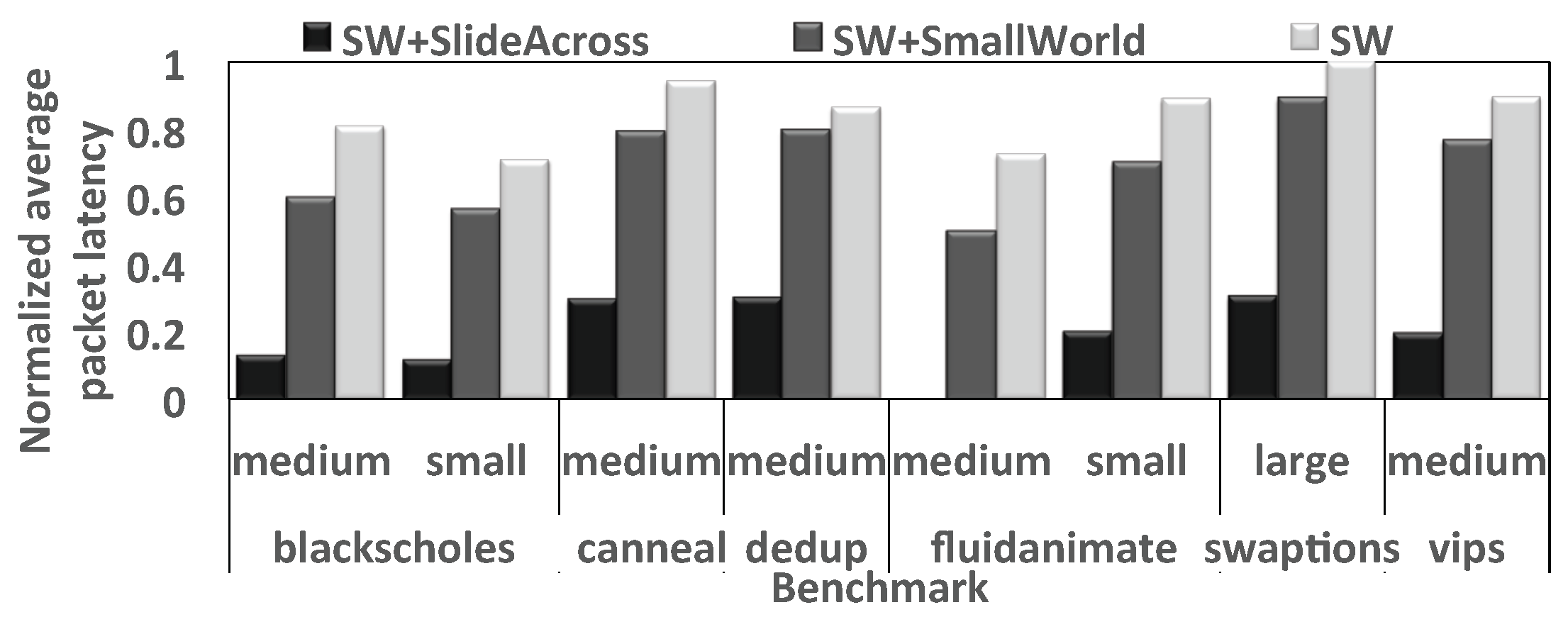
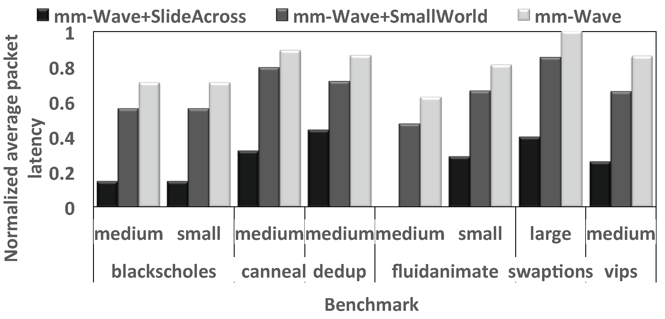
4.6. Impact of the Proposed Router on WiNoCs
5. Conclusions
Author Contributions
Conflicts of Interest
References
- Siozios, K.; Bartzas, A.; Soudris, D. Three Dimensional Network-on-Chip Architectures. In Networks-on-Chips: Theory and Practice; Fayez Gebali, H.E., El-Kharashi, M.W., Eds.; CRC Press: Boca Raton, FL, USA, 2009; pp. 1–28. [Google Scholar]
- Agyeman, M.O.; Ahmadinia, A.; Shahrabi, A. Heterogeneous 3D network-on-chip architectures: Area and power aware design techniques. J. Circuits Syst. Comput. 2013, 22, 1350016. [Google Scholar] [CrossRef]
- Agyeman, M.O.; Ahmadinia, A.; Bagherzadeh, N. Performance and Energy Aware Inhomogeneous 3D Networks-on-Chip Architecture Generation. IEEE Trans. Parallel Distrib. Syst. 2015, 27, 1756–1769. [Google Scholar] [CrossRef]
- Matsutani, H.; Bogdan, P.; Marculescu, R.; Take, Y.; Sasaki, D.; Zhang, H.; Koibuchi, M.; Kuroda, T.; Amano, H. A case for wireless 3D NoCs for CMPs. In Proceedings of the 2013 18th Asia and south Pacific Design Automation Conference (ASP-DAC), Yokohama, Japan, 22–25 January 2013; pp. 23–28. [Google Scholar]
- Agyeman, M.O. A Study of Optimization Techniques for 3D Networks-on-Chip Architectures for Low Power and High Performance Applications. Int. J. Comput. Appl. 2015, 121, 1–8. [Google Scholar]
- Agyeman, M.O.; Wan, J.X.; Vien, Q.T.; Zong, W.; Yakovlev, A.; Tong, K.; Mak, T. On the Design of Reliable Hybrid Wired-Wireless Network-on-Chip Architectures. In Proceedings of the IEEE Embedded Multicore/Many-Core Systems-on-Chip (MCSoC), Turin, Italy, 23–25 September 2015; pp. 251–258. [Google Scholar]
- Heirman, W.; Dambre, J.; Stroobandt, D.; Van Campenhout, J. Rent’s rule and parallel programs: Characterizing network traffic behavior. In Proceedings of the 2008 International Workshop on System Level Interconnect Prediction (SLIP), Newcastle, UK, 5–6 April 2008; pp. 87–94. [Google Scholar]
- Woo, S.C.; Ohara, M.; Torrie, E.; Singh, J.P.; Gupta, A. The SPLASH-2 programs: Characterization and methodological considerations. In Proceedings of the 22nd Annual International Symposium on Computer Architecture (ISCA), S. Margherita Ligure, Italy, 22–24 June 1995; Volume 23, pp. 24–36. [Google Scholar]
- Carlson, T.E.; Heirman, W.; Eeckhout, L. Sniper: Exploring the level of abstraction for scalable and accurate parallel multi-core simulation. In Proceedings of the 2011 International Conference for High Performance Computing, Networking, Storage and Analysis (SC’11), Seattle, WA, USA, 12 November 2011; p. 52. [Google Scholar]
- Duato, J. A new theory of deadlock-free adaptive routing in wormhole networks. TPDS 1993, 4, 1320–1331. [Google Scholar]
- Kim, J. Low-cost router microarchitecture for on-chip networks. In Proceedings of the Microarchitecture (MICRO), New York, NY, USA, 12–16 December 2009; pp. 255–266. [Google Scholar]
- Ausavarungnirun, R.; Fallin, C.; Yu, X.; Chang, K.K.W.; Nazario, G.; Das, R.; Loh, G.H.; Mutlu, O. Design and evaluation of hierarchical rings with deflection routing. In Proceedings of the IEEE 26th International Symposium on Computer Architecture and High Performance Computing (SBAC-PAD), Paris, France, 22–24 October 2014; pp. 230–237. [Google Scholar]
- Jerger, N.E.; Peh, L.S. On-Chip Networks. Morgan and Claypool Publishers: San Rafael, CA, USA, 2009; pp. 1–141. [Google Scholar]
- Owens, J.D.; Dally, W.J.; Ho, R.; Jayasimha, D.N.; Keckler, S.W.; Peh, L.S. Research Challenges for On-Chip Interconnection Networks. IEEE Micro 2007, 27, 96–108. [Google Scholar] [CrossRef]
- Kim, J.; Park, D.; Theocharides, T.; Vijaykrishnan, N.; Das, C.R. A low latency router supporting adaptivity for on-chip interconnects. In Proceedings of the DAC, Shanghai, China, 18–21 January 2005; pp. 559–564. [Google Scholar]
- Gratz, P.; Grot, B.; Keckler, S.W. Regional congestion awareness for load balance in networks-on-chip. In Proceedings of the IEEE 14th International Symposium on High Performance Computer Architecture (HPCA), Salt Lake City, UT, USA, 16–20 Febuary 2008; pp. 203–214. [Google Scholar]
- Peh, L.S.; Dally, W.J. A delay model and speculative architecture for pipelined routers. In Proceedings of the IEEE 14th International Symposium on High Performance Computer Architecture (HPCA), Monterrey, Nuevo Leon, Mexico, 20–24 January 2001; pp. 255–266. [Google Scholar]
- He, Y.; Sasaki, H.; Miwa, S.; Nakamura, H. McRouter: Multicast within a router for high performance network-on-chips. Proceedings of 12th International Conference on Parallel Computing Technologies (PaCT-2013), Edinburgh, Scotland, UK, 7–11 October 2013; pp. 319–330. [Google Scholar]
- Krishna, T.; Postman, J.; Edmonds, C.; Peh, L.S.; Chiang, P. Swift: A swing-reduced interconnect for a token-based network-on-chip in 90 nm cmos. In Proceedings of the 2010 IEEE International Conference on Computer Design (ICCD 2010), Amsterdam, The Netherlands, 3–6 October 2010; pp. 439–446. [Google Scholar]
- Chen, C.H.O.; Park, S.; Krishna, T.; Subramanian, S.; Chandrakasan, A.P.; Peh, L.S. SMART: A single-cycle reconfigurable NoC for SoC applications. In Proceedings of the Design Automation and Test in Europe (DATE), Grenoble, France, 18–22 March 2013; pp. 338–343. [Google Scholar]
- Jain, T.N.; Gratz, P.V.; Sprintson, A.; Choi, G. Asynchronous bypass channels: Improving performance for multi-synchronous nocs. In Proceedings of the Networks-on-Chip (NOCS), Grenoble, France, 3–6 May 2010; pp. 51–58. [Google Scholar]
- Krishna, T.; Chen, C.H.O.; Kwon, W.C.; Peh, L.S. Breaking the on-chip latency barrier using SMART. In Proceedings of the High Performance Computer Architecture (HPCA), Shenzhen, China, 23–27 February 2013; pp. 378–389. [Google Scholar]
- Kumar, R.; Yang, Y.S.; Choi, G. Intra-flit skew reduction for asynchronous bypass channel in nocs. In Proceedings of the VLSI Design, Chennai, India, 2–7 January 2011; pp. 238–243. [Google Scholar]
- Park, S.; Krishna, T.; Chen, C.H.; Daya, B.; Chandrakasan, A.; Peh, L.S. Approaching the theoretical limits of a mesh NoC with a 16-node chip prototype in 45 nm SOI. In Proceedings of the Design Automation Conference (DAC 2012), San Francisco, CA, USA, 3–7 June 2012; pp. 398–405. [Google Scholar]
- Kim, J.; Balfour, J.; Dally, W. Flattened butterfly topology for on-chip networks. In Proceedings of the Microarchitecture (MICRO), Chicago, IL, USA, 1–5 December 2007; IEEE Computer Society: Washington, DC, USA; pp. 172–182. [Google Scholar]
- Grot, B.; Hestness, J.; Keckler, S.W.; Mutlu, O. Express cube topologies for on-chip interconnects. In Proceedings of the High Performance Computer Architecture (HPCA), Raleigh, NC, USA, 14–18 February 2009; pp. 163–174. [Google Scholar]
- Vivet, P.; Thonnart, Y.; Lemaire, R.; Beigne, E.; Bernard, C.; Darve, F.; Lattard, D.; Miro-Panades, I.; Santos, C.; Clermidy, F.; et al. 8.1 A 4 × 4 × 2 homogeneous scalable 3D network-on-chip circuit with 326MFlit/s 0.66pJ/b robust and fault-tolerant asynchronous 3D links. In Proceedings of the IEEE International Solid-State Circuits Conference (ISSCC), San Francisco, CA, USA, 21 February 2016; pp. 146–147. [Google Scholar]
- Carloni, L.P.; Pande, P.; Xie, Y. Networks-on-chip in emerging interconnect paradigms: Advantages and challenges. In Proceedings of the ACM/IEEE International Symposium on Networks-on-Chip (NOCS), San Diego, CA, USA, 10–13 May 2009; pp. 93–102. [Google Scholar]
- Kim, J.; Nicopoulos, C.; Park, D.; Das, R.; Xie, Y.; Narayanan, V.; Yousif, M.S.; Das, C.R. A novel dimensionally-decomposed router for on-chip communication in 3D architectures. SIGARCH Comput. Archit. News 2007, 35, 138–149. [Google Scholar] [CrossRef]
- Li, F.; Nicopoulos, C.; Richardson, T.; Xie, Y.; Narayanan, V.; Kandemir, M. Design and Management of 3D Chip Multiprocessors Using Network-in-Memory. In Proceedings of the International Symposium on Computer Architecture (ISCA), Boston, MA, USA, 17–21 June 2006; pp. 130–141. [Google Scholar]
- Xie, Y.; Cong, J.; Sapatneker, S. System-Level 3D IC Cost Analysis and Design Exploration. In Three Dimensional Integrated Circuit Design; Springer: New York City, USA, 2010; pp. 261–280. [Google Scholar]
- Xu, T.; Liljeberg, P.; Tenhunen, H. A study of Through Silicon via impact to 3D Network-on-Chip design. In Proceedings of the 2010 International Conference on Electronics and Information Engineering (ICEIE), Kyoto, Japan, 1–3 August 2010; pp. 333–337. [Google Scholar]
- Liu, C.; Zhang, L.; Han, Y.; Li, X. Vertical interconnects squeezing in symmetric 3D mesh Network-on-Chip. In Proceedings of the Asia and south Pacific Design Automation Conference (ASP-DAC), Yokohama, Japan, 25–28 January 2011; pp. 357–362. [Google Scholar]
- Wang, Y.; He, Y.-N.; Zhang, L.; Fu, B.Z.; Liu, C.; Li, H.-W.; Li, X. Economizing TSV Resources in 3D Network-on-Chip Design. IEEE Trans. Very Large Scale Integr. (VLSI) Syst. 2014, 23, 493–506. [Google Scholar] [CrossRef]
- Pasricha, S. Exploring serial vertical interconnects for 3D ICs. In Proceedings of the Design Automation Conference (DAC), San Francisco, CA, USA, 26–31 July 2009; pp. 581–586. [Google Scholar]
- Pasricha, S. A Framework for TSV Serialization-aware Synthesis of Application Specific 3D Networks-on-Chip. Proceesings of the International Conference on VLSI Design (VLSID), Honolulu, HI, USA, 13 June 2012; pp. 268–273. [Google Scholar]
- Xu, T.C.; Schley, G.; Liljeberg, P.; Radetzki, M.; Plosila, J.; Tenhunen, H. Optimal placement of vertical connections in 3D Network-on-Chip. J. Syst. Archit. 2013, 59, 441–454. [Google Scholar] [CrossRef]
- Miller, F.; Wild, T.; Herkersdorf, A. TSV-virtualization for Multi-protocol-Interconnect in 3D-ICs. Proceesings of the Euromicro Conference on Digital System Design (DSD), Cesme, Izmir, Turkey, 5–8 September 2012; pp. 374–381. [Google Scholar]
- Agyeman, M.O.; Ahmadinia, A.; Shahrabi, A. Efficient Routing Techniques in Heterogeneous 3D Networks-on-Chip. Parallel Comput. 2013, 39, 389–407. [Google Scholar] [CrossRef]
- Bose, A.; Ghosal, P.; Mohanty, S.P. A Low Latency Scalable 3D NoC Using BFT Topology with Table Based Uniform Routing. In Proceedings of the IEEE Computer Society Annual Symposium on VLSI (ISVLSI), Tampa, FL, USA, 9–11 July 2014; pp. 136–141. [Google Scholar]
- Rose, A.; Ramachandran, S.R. Genetic Algorithm Based Optimization of Vertical Links for Efficient 3D NoC Multicore Crypto Processor. Int. Symp. Qual. Electron. Des. 2013, 8, 1082–1090. [Google Scholar]
- Bahmani, M.; Sheibanyrad, A.; Petrot, F.; Dubois, F.; Durante, P. A 3D-NoC Router Implementation Exploiting Vertically-Partially-Connected Topologies. Proceesings of the IEEE Computer Society Annual Symposium on VLSI (ISVLSI), Amherst, MA, USA, 19–21 August 2012; pp. 9–14. [Google Scholar]
- OpokuAgyeman, M. 3D Networks-on-Chip Architecture Optimization for Low Power Design; LAP LAMBERT Academic Publishing: Saarbrücken, Germany, 2015. [Google Scholar]
- Agyeman, M.O.; Ahmadinia, A. Optimised Application Specific Architecture Generation and Mapping Approach for Heterogeneous 3D Networks-on-Chip. Proceesings of the IEEE International Conference on Computational Science and Engineering, Sydney, Australia, 3–5 December 2013; pp. 794–801. [Google Scholar]
- Yu, X.; Sah, S.; Deb, S.; Pande, P.; Belzer, B.; Heo, D. A wideband body-enabled millimetre-wave transceiver for wireless Network-on-Chip. Proceesings of the Midwest Symposium on Circuits and Systems (MWSCAS), Seoul, Korea, 7–10 August 2011; pp. 1–4. [Google Scholar]
- Xiao, C.; Huang, Z.; Li, D. A Tutorial for Key Problems in the Design of Hybrid Hierarchical NoC Architectures with Wireless/RF. Smart CR 2013, 3, 425–436. [Google Scholar] [CrossRef]
- Agyeman, M.O.; Vien, Q.T.; Ahmadnia, A.; Yakovlev, A.; Tong, K.F.; Mak, T. A Resilient 2-D Waveguide Communication Fabric for Hybrid Wired-Wireless NoC Design. IEEE Trans. Parallel Distrib. Syst. 2016, 28, 359–373. [Google Scholar]
- Sun, C.; Sun, C.; Chen, C.H.O.; Kurian, G.; Wei, L.; Miller, J.; Agarwal, A.; Peh, L.S.; Stojanovic, V. DSENT-a tool connecting emerging photonics with electronics for opto-electronic networks- on-chip modeling. In Proceedings of the NOCS, Copenhagen, Denmark, 9–11 May 2012; pp. 201–210. [Google Scholar]
- Becker, D.U. Efficient Microarchitecture for Network-on-Chip Routers. Ph.D. Thesis, Stanford University, Stanford, CA, USA, 2012. [Google Scholar]
- Mullins, R.; west, A.; Moore, S. Low-latency virtual-channel routers for on-chip networks. In Proceedings of the International Symposium on Computer Architecture (ISCA), Munich, Germany, 19–23 June 2004; Volume 32, p. 188. [Google Scholar]
- Kumar, A.; Kunduz, P.; Singhx, A.P.; Pehy, L.S.; Jhay, N.K. A 4.6 Tbits/s 3.6 GHz single-cycle NoC router with a novel switch allocator in 65 nm CMOS. In Proceedings of the International Conference on Computer Design (ICCD), Lake Tahoe, CA, USA, 7–10 October 2007; pp. 63–70. [Google Scholar]
- Dally, W.; Towles, B. Principles and Practices of Interconnection Networks; Morgan Kaufmann Publishers Inc.: San Francisco, CA, USA, 2003. [Google Scholar]
- Catania, V.; Mineo, A.; Monteleone, S.; Palesi, M.; Patti, D. Cycle-Accurate Network on Chip Simulation with Noxim. ACM Trans. Model. Comput. Simul. 2016, 27, 1–25. [Google Scholar] [CrossRef]
- Fazzino, F.; Palesi, M.; Patti, D. Noxim: Network-on-Chip Simulator. Available online: http://sourceforge.net/projects/noxim (accessed on 31 December 2008).
- Hu, J.; Marculescu, R. Energy- and performance-aware mapping for regular NoC architectures. IEEE Trans. Comput.-Aided Des. Integr. Circuits Syst. 2005, 24, 551–562. [Google Scholar]
- Dick, R. Embedded System Synthesis Benchmarks Suite (E3S). Available online: ziyang.eecs.umich.edu/dickrp/e3s (accessed on 25 April 2017).
- Binkert, N.; Dreslinski, R.; Hsu, L.; Lim, K.; Saidi, A.; Reinhardt, S. The M5 Simulator: Modeling Networked Systems. IEEE Micro 2006, 26, 52–60. [Google Scholar] [CrossRef]
- Bienia, C.; Kumar, S.; Singh, J.P.; Li, K. The PARSEC Benchmark Suite: Characterization and Architectural Implications. In Proceedings of the Parallel Architectures and Compilation Techniques, Toronto, ON, Canada, 25–29 October 2008; pp. 72–81. [Google Scholar]
- Hestness, J.; Grot, B.; Keckler, S.W. Netrace: Dependency-driven Trace-based Network-on-chip Simulation. In Proceedings of the 3rd International Workshop on Network on Chip Architectures (NoCArc 2010), Atlanta, GA, USA, 4–8 December 2010; pp. 31–36. [Google Scholar]


| Mesh Size | , |
|---|---|
| Number of virtual-channels per port | 4 |
| Escape channel | 1 |
| Buffer depth | 6 flits |
| Packet length | 2–7 flits |
| PIR (packets/cycle/core) | 0.005 to 0.1 |
| Warm up cycles | 2000 |
| Simulation cycles | 50,000 |
| Frequency | 1 GHz |
|---|---|
| ISA | x86-64 |
| Core | 64 cores, Two-way out-of-order, 8 memory controller |
| L1 ICache | 32 KB, private, 4-way |
| L1 DCache | 32 KB, private, 4-way |
| L2 Cache | 512 KB, shared, 16-way |
| Cache coherence | MESI |
| Main memory latency | 80 cycles |
| Flit width | 128 bits |
| Network Size | 8×8 |
| Title | Area (m) | Power (mW) |
|---|---|---|
| Adaptive Router | 56,896.4 | 95.6 |
| Slide Across | 59,059.8 | 96.9 |
| Bypass Overhead | 3.66% | 1.40% |
| Title | Dynamic (mW) | Leakage (mW) |
|---|---|---|
| Data Flit | 1.025 | |
| Data + Lookahead Flit | 1.249 | |
| Overhead | 21.85% | 21.87% |
| Benchmark | Input Set | Cycles | Total Packets |
|---|---|---|---|
| blackscholes | small | 255 M | 5.2 M |
| blackscholes | medium | 133 M | 7.2 M |
| channeal | medium | 140 M | 8.6 M |
| dedup | medium | 146 M | 2.6 M |
| fluidanimate | small | 127 M | 2.1 M |
| fluidanimate | medium | 144 M | 4.6 M |
| swaptions | large | 204 M | 8.8 M |
| vips | medium | 147 M | 0.9 M |
| NoC Dimension | |
|---|---|
| Virtual channels (VC) per port | 4 |
| NoC buffer (flit depth) | 6 |
| Links and NoC buffer width | 128 bits |
| Transceiver nodes | 5 |
| FDMAcarrier frequencies per node | 128 |
| Fixed BER | mm-wave: ; wireline: ; SW: |
© 2017 by the authors. Licensee MDPI, Basel, Switzerland. This article is an open access article distributed under the terms and conditions of the Creative Commons Attribution (CC BY) license (http://creativecommons.org/licenses/by/4.0/).
Share and Cite
Opoku Agyeman, M.; Zong, W.; Yakovlev, A.; Tong, K.-F.; Mak, T. Extending the Performance of Hybrid NoCs beyond the Limitations of Network Heterogeneity. J. Low Power Electron. Appl. 2017, 7, 8. https://doi.org/10.3390/jlpea7020008
Opoku Agyeman M, Zong W, Yakovlev A, Tong K-F, Mak T. Extending the Performance of Hybrid NoCs beyond the Limitations of Network Heterogeneity. Journal of Low Power Electronics and Applications. 2017; 7(2):8. https://doi.org/10.3390/jlpea7020008
Chicago/Turabian StyleOpoku Agyeman, Michael, Wen Zong, Alex Yakovlev, Kin-Fai Tong, and Terrence Mak. 2017. "Extending the Performance of Hybrid NoCs beyond the Limitations of Network Heterogeneity" Journal of Low Power Electronics and Applications 7, no. 2: 8. https://doi.org/10.3390/jlpea7020008