Review

High-Feedback Operation of Power Electronic Converters

by
Zhanybai T. Zhusubaliyev
1,*,
Erik Mosekilde
2,
Alexey I. Andriyanov
3 and
Gennady Y. Mikhal'chenko
4
1
Department of Computer Science, South West State University, 50 Years of October Street, 94,Kursk 305040, Russia
2
Department of Physics, Technical University of Denmark, 2800 Lyngby, Denmark
3
Department of Electronics, Radioelectronic and Electrotechnical Systems, Bryansk State TechnicalUniversity, Bulvar 50 Letiya Oktyabrya, 7, Bryansk 241035, Russia
4
Department of Industrial Electronics, Tomsk State University of Control Systems andRadioelectronics, 40 Lenina Prospect, Tomsk 634050, Russia
*
Author to whom correspondence should be addressed.
Electronics 2013, 2(2), 113-167; https://doi.org/10.3390/electronics2020113
Submission received: 29 November 2012 / Revised: 4 February 2013 / Accepted: 11 February 2013 / Published: 27 March 2013
(This article belongs to the Special Issue Feature Papers)

Abstract

:
The purpose of this review is to provide a survey of some of the most important bifurcation phenomena that one can observe in pulse-modulated converter systems when operating with high corrector gain factors. Like other systems with switching control, electronic converter systems belong to the class of piecewise-smooth dynamical systems. A characteristic feature of such systems is that the trajectory is “sewed” together from subsequent discrete parts. Moreover, the transitions between different modes of operation in response to a parameter variation are often qualitatively different from the bifurcations we know for smooth systems. The review starts with an introduction to the concept of border-collision bifurcations and also demonstrates the approach by which the full dynamics of the piecewise-linear, time-continuous system can be reduced to the dynamics of a piecewise-smooth map. We describe the main bifurcation structures that one observes in three different types of converter systems: (1) a DC/DC converter; (2) a multi-level DC/DC converter; and (3) a DC/AC converter. Our focus will be on the bifurcations by which the regular switching dynamics becomes unstable and is replaced by ergodic or resonant periodic dynamics on the surface of a two-dimensional torus. This transition occurs when the feedback gain is increased beyond a certain threshold, for instance in order to improve the speed and accuracy of the output voltage regulation. For each of the three converter types, we discuss a number of additional bifurcation phenomena, including the formation and reconstruction of multi-layered tori and the appearance of phase-synchronized quasiperiodicity. Our numerical simulations are compared with experimentally observed waveforms.

1. Introduction

The field of power electronics has undergone a dramatic evolution during the last few decades [1]. For many applications, the classic transformer with its heavy iron anchor and copper windings has been replaced by a smaller, lighter, and often also significantly cheaper switch-mode operated converter system [2,3]. The use of relatively high switching frequencies has reduced the requirements on the size of the output filter components, and together these developments have opened the way for a broad range of new applications [4,5,6], including applications in portable PCs and cellular phones [7], as backup systems for sensitive computer systems and hospital equipment, and as main electric power supplies at remote locations. Today, power electronic systems with switching operation are used in practically all sectors of our society. Examples from the industry and transportation sector are aircraft electronics, traction regulators in trains, and power supplies for electric vehicles [8]. An introduction to some of the complex nonlinear phenomena that one can observe in power electronics systems may be found in the book by Banerjee and Verghese [9].

1.1. Power Electronic Converter Systems

To characterize the various types of switch-mode operated converter systems, let us first note that DC/DC converters use a fixed DC power source, such as a car battery, to provide a DC power output at an adjustable voltage (or current) level. Converters of this type may be used, for instance, as power supplies for navigation instruments in boats, for liquid crystal displays, or for solar-energy driven refrigeration and cooling systems. By coupling two or more DC/DC converters in series, one can obtain an output voltage that exceeds the available input voltage.
DC/AC converters similarly provide an AC power output of variable frequency and amplitude from a fixed DC source. In this case, the reference voltage that controls the switching process must prescribe the desired waveform for the output voltage, and the converter must be fast enough to follow this waveform with the required accuracy. This type of converter may be used to provide AC power at the normal utility frequency from a storage battery and thus allows TV sets, vacuum cleaners, and other common household appliances to be used in summerhouses, etc. DC/AC converters may also be used as so-called grid-tie inverters to convert the low voltage, high current DC power output from solar cell panels into line-frequency and -voltage AC power that can be fed directly into the public utility network [10].
The output voltage of a switch-mode converter is regulated by controlling the time that the output load is connected to the input voltage with a properly designed L C -filter acting to smooth out the ripple (or noise) associated with the switching process. More advanced DC/DC converters may involve the use of a multilevel architecture in which input voltage is provided at several different levels. A main advantage of this design is that the output voltage can be supplied with higher efficiency and less distortion. At the same time one can generally reduce the cost of the individual components by accepting a lower voltage rating.
Designing a power electronic converter system for a specific purpose involves a significant number of mutually connected problems related to the choice of an appropriate architecture, feedback regulator, switching frequency, and filter characteristic [11,12]. One has to ensure that requirements on the accuracy of the output voltage regulation, the level of ripple and noise from the switching process and the maximal tolerable losses are all met [13,14]. One has to consider the output impedance in relation to the expected load impedance and check that variations of the output voltage with changes in the input voltage, the ambient temperature, or the values of specific components are acceptable. One also has to investigate what happens under special operational conditions, including start-up, input power failure, short circuiting of the output load, or insulation breakdown. Finally, one needs to examine how the system behaves outside of its normal range of operation and to determine how large the safety margin to such other regimes needs to be.
Optimization of the efficiency is one of the main considerations in the design of a switch-mode modulated converter system. However, as efficiency increases, dissipation decreases, and the system may become vulnerable to some form of instability. High feedback gain is desirable in order to ensure a fast and accurate adjustment of the output signal to variations in the reference signal. However, in connection with the delay in the feedback loop (associated typically with the charging and discharging of the output filter capacitor), increasing the feedback gain above a certain threshold is likely to give birth to a new oscillatory component in the system. Together with the already existing switching dynamics, this produces so-called torus dynamics, i.e., a form of behavior where two oscillatory components generate a beating dynamics (known as quasiperiodicity) interrupted in parameter space by a dense set of resonance regions in which the two modes synchronize with one another at different frequency ratios.

1.2. Bifurcations in a Piecewise-Smooth System

Like other systems with switching control, electronic converter systems belong to a class of piecewise-smooth dynamical systems [15,16,17]. A characteristic feature of such systems is that the phase space is divided into regions with distinctly different dynamics. At the boundaries between these regions, the trajectories are so to speak ‘sewed’ together from their distinct smooth parts [18,19]. Moreover, the transitions between different dynamical states that can occur in response to the variation of one or more parameters are qualitatively different from the transitions we know from the classical bifurcation theory for smooth dynamical systems [20] .
In general, one can distinguish between two different types of bifurcations for piecewise smooth systems. The first type is similar to the bifurcations we know for smooth systems. They include both local bifurcations such as saddle-node, period-doubling and torus-birth (Andronov–Hopf) bifurcations, where a periodic orbit loses its stability as one (or two) Floquet multiplier(s) (eigenvalues for the corresponding Poincaré map) crosses out of the unit circle in the complex plane, and global bifurcations (homoclinic and heteroclinic bifurcations), in which a connection is established from a saddle cycle and back to the same (or to another) saddle. However, the form of these bifurcations is usually modified by the piecewise-smooth character of the system. The bifurcation diagram for the torus-birth bifurcation, for instance, often deviates from the parabolic form that one observes for smooth systems.
For a periodic cycle, the second type of bifurcations, referred to as border-collision (or C-) bifurcations [21,22,23], typically involve an abrupt jump of one (or a pair of) multipliers from the inside to the outside of the unit circle. A stable focus cycle, for instance, may turn into an unstable focus cycle as two complex conjugated multipliers under variation of a parameter jump out of the unit circle [24,25]. Border-collision bifurcations may give rise to a direct transition from period-2 to period-3 dynamics [23], or in fact to almost any form of periodic, quasiperiodic or chaotic dynamics. It is also possible that an ergodic torus can arise directly from a stable node cycle [26]. Besides abrupt jumps of the multipliers in the complex plane, one of the features that characterize the border-collision bifurcations is that the amplitude of the appearing mode tends to grow linearly with the distance to the bifurcation point as opposed to the parabolic growth that one finds for smooth bifurcations.
The complexity of the nonlinear dynamic phenomena we observe in power electronic converter systems partly derives from the coexistence of the two different types of bifurcation and partly from the large number of new bifurcation phenomena that border collision can give rise to. In this connection, it is interesting to note that many practical problems in mechanics and mechanical engineering involve collisions and/or stick-slip friction. Such systems also lead to piecewise-smooth dynamics and to the appearance of both border-collision bifurcations [27,28] and of the related phenomena of sliding and grazing bifurcations [29,30,31]. Classic examples in this area are metal cutting processes [32], rolling railway wheels [33], and mooring at sea [34]. Other examples include rotating machines with finite clearance [35] and vibration absorbers [36]. It may also be of interest to know that the same concepts can be applied in the study of management systems where discrete decisions, made on the basis of current information, from time to time will redirect the course of the system [37,38].

1.3. Purpose and Content of the Review

In a series of papers published over the last decade we have discussed different forms of instabilities and nonlinear dynamic phenomena that can arise in pulse-width modulated DC/DC and DC/AC converters operating with high feedback gain factors [39,40,41,42,43,44,45,46]. This work has particularly focused on the mechanisms by which border-collision bifurcations can lead to the appearance of quasiperiodic and/or resonant periodic dynamics as a pair of complex conjugated Floquet multipliers for the regular switching cycle jumps from the inside to the outside of the unit circle in the complex plane [41,42]. We have demonstrated experimentally how this type of bifurcation can occur in both DC/DC [43] and DC/AC converters, and we have illustrated how the usual smooth torus-birth bifurcation (also known as Andronov–Hopf or secondary Hopf bifurcation) is modified by the non-smooth character of the converter. We have also studied border-collision processes among the various resonant and non-resonant modes on the two-dimensional torus [39,40] and, in a couple of recent publications, we have illustrated the appearance [45] and reconstruction [46] of multi-layered tori, i.e., of sets of ergodic or resonant tori, emerged one within the other.
Different forms of instability in electronic converter systems have also been studied by a significant number of other authors. Aroudi et al. [47], for instance, have observed the nearly abrupt transition to quasiperiodicity via a modified Andronov–Hopf bifurcation followed by a transition to chaotic dynamics through torus breakdown. Mazumder et al. [48] have demonstrated how instabilities in a closed loop converter system can arise on both a slow and a fast scale, and Dai et al. [49] have described a slow-scale instability in single-phase power-factor-correction power supplies. More recently, Aroudi et al. [50] have determined the asymptotic slow-scale stability boundary, while Rodriguez et al. [51] have applied a ripple-based approach to predict the fast-scale instability in DC/DC switching power supplies.
The purpose of the present review is to provide a survey of some of the most important bifurcation phenomena that one can observe in pulse-modulated converter systems. With this aim we shall first analyze a simple DC/DC converter with a single input level and thereafter examine both a multilevel DC/DC converter and a DC/AC converter. The focus of our presentation will be on the bifurcations through which the regular (period-1) switching dynamics is replaced by ergodic or resonant periodic dynamics on the surface of the torus. However, for each of the considered converters we shall present examples of additional bifurcation phenomena. To provide a relevant background for our analysis, the review starts with an illustration of some of the basic features of border-collision bifurcations. This is supported by an illustration of the approach by which the time-continuous dynamics of a piecewise linear system can be replaced by the piecewise-smooth dynamics of a discrete-time map.

2. Border-Collision Bifurcations in Piecewise-Linear Systems

Many systems of practical interest are non-smooth. In particular, the repeated switching of the circuit topology characteristic of pulse-modulated control systems destroys the smoothness of their temporal dynamics. The trajectory then consists of a sequence of arcs each describing the smooth dynamics between two switching processes. Each time a switching occurs, the topology of the circuit changes and, with appropriate initial conditions, the system will continue the next part of its trajectory in accordance with the equations of motion for the new topology.
For mechanical systems, lack of smoothness is characteristic of problems involving impacts or stick-slip motion. As listed in the introduction, classical examples include metal cutting processes and rotating machines with finite clearances. Other examples are die tossing [52] and the operation of mechanical randomizers such as, for instance, the pin-ball machine (or Galton apparatus) [53]. In view of improving the resistance to earthquakes for new constructions (as well as for historic monuments), attempts are presently being made to use concepts from the theory of non-smooth dynamical systems to analyze the dynamics and collapse of buildings.
In information processing, lack of smoothness arises, for instance, from the use of signal limiters [54] and from the process of digitalization. As mentioned above, the discrete decisions characteristic of managerial systems produce non-smooth dynamics, and the same is true for macroeconomic systems that operate with specific intervention thresholds in order to limit the variation of certain exchange rates or to control the price fluctuations of particular commodities. This wide range of applicability obviously contributes to the rapidly growing interest in the dynamics of piecewise-smooth systems.
The purpose of this section is to use a few simple examples to explain how and why the dynamics of piecewise-linear systems differs qualitatively from the dynamics we observe in smooth systems. Period-doubling and Hopf bifurcations, for instance, are modified such that the emerging mode is born with a finite amplitude. At the same time, the period-doubling cascade is truncated, and border-collision bifurcations are found to allow direct transitions from period-1 dynamics to almost any form of behavior.

2.1. The Sewing Approach

The dynamics of a mooring buoy connected via a cable to a large oil tanker and subjected to the regular forcing from the waves of the ocean may be considered as an example of a piecewise-linear mechanical system [34]. The buoy can be pictured as an inverted pendulum that, by virtue of its buoyancy, displays a state of equilibrium in the upright position. For small excursions around this state, the one-dimensional dynamics of the forced system may then be represented by
d 2 x d t 2 + α d x d t + F ( x ) = B cos t
where α represents the viscous friction, F ( x ) the restoring force, and B the amplitude of the periodic forcing. The restoring force has a contribution h 1 x from the buoyancy, and there is also a contribution to F ( x ) from the force exerted by the mooring cable. In the crudest possible approximation we may assume this second force to vanish when the cable is slackened, but to contribute an elastic term h 2 x when, for x < 0 , the cable is stretched. Together these contributions define a piecewise linear restoring force of the form
F ( x ) = ( h 1 + h 2 ) x , x 0 h 1 x , x > 0
where h 1 and h 2 are constant parameters.
On both sides of the stretching point x = 0 , the system is linear and in these regions, the equation of motion can be solved analytically [55]. However, to obtain the total solution we must connect the partial solutions across the sewing border at x = 0 . For our simple mechanical oscillator, the sewing conditions are that both the position x and the velocity d x / d t must vary continuously across this border.
Figure 1 shows the results of such a sewing procedure for different values of the model parameters. For certain parameter values, the solutions can be connected in such a way that the total dynamics is periodic (Figure 1a). For other values, however, the individual pieces cannot be connected into a trajectory that closes to itself, and our simple piecewise-linear system displays chaotic dynamics (Figure 1b). In reality, the cable force may not vary as abruptly as we have assumed in the above model. However, this is not an essential objection to our discussion. Many realistic mechanical systems involve forces that, at least within a reasonable modeling framework, can be considered to change abruptly. This is the case, for instance, for the above mentioned vibration dampers [36] and rolling railway wheel sets [33] that involve collisions between hard bodies. In a similar way, our discussion of different power electronic converter systems will assume that the switching process is instantaneous and ideal.
Figure 1. Phase space projections of the motion of a simplified mooring buoy. The mooring cable is stretched for x < 0 and loose for x > 0 . On both sides of the stretching point, the trajectory can be determined analytically, but connecting pieces of the trajectory across the sewing line in many cases does not lead to a periodic orbit. (a) Periodic solution for α = 2 , h 1 = 40 , h 2 = 360 and B = 100 ; (b) Chaotic solution for α = 0 . 1 , h 1 = 40 , h 2 = 360 , and B = 50 .
Electronics 02 00113 g001

2.2. Modification of the Period-Doubling Bifurcations

It is well-known that the simple logistic map
x k = f ( x k - 1 ) = λ x k - 1 ( 1 - x k - 1 ) , k = 1 , 2 , 3 . . . .
for increasing values of λ gives rise to a cascade of period-doubling bifurcations starting with the first period doubling at λ = 3 . 0 and accumulating in a transition to chaos at the Feigenbaum point λ F = 3 . 571 . . . . It is also known that this transition is generic to a class of smooth one-dimensional maps with a quadratic extremum and that it is characterized by two universal scaling parameters [56,57]. The first period doubling takes place when the slope f ( x k - 1 ) of the map, evaluated at the fixed point x * , becomes equal to - 1 . However, it is the second and third derivatives of the map, f ( x * ) and f ( x * ) , that determine the form of the solution close to the bifurcation. If the so-called Schwarzian derivative [58]
S f ( x ) f ( x ) f ( x ) - 3 2 f ( x ) f ( x ) 2
is negative, the period doubling will be supercritical, and a stable period-2 solution will be born.
In the opposite case where S f ( x ) is positive, the bifurcation is subcritical, and an unstable period-2 cycle that has existed together with the stable fixed point will disappear in the bifurcation. For the logistic map, f ( x ) vanishes and f ( x ) = - 2 λ 0 for all values of x. Hence, S f ( x * ) is negative, and the bifurcation leads to a stable period-2 solution. Moreover, the Schwarzian derivative has the interesting property that if it is negative for the map f ( x ) , then it is negative for all iterations f n ( x ) , n = 1 , 2 , 3 . . . of that map. Therefore, once started, the period-doubling cascade will also continue to display supercritical bifurcations.
If the logistic map is replaced by the piecewise linear skew tent map [59]
x k = T l , p ( x k - 1 ) = l x k - 1 + c , 0 x k - 1 d p ( x k - 1 - 1 ) , d x k - 1 1
with l > 0 and p < 0 denoting the slopes of the two line segments, the transition to chaos takes a very different form. To reduce the number of parameters let us simplify the situation by choosing
c = 1 - l 1 + 1 p and d = 1 + 1 p
such that the map becomes continuous, and its top point falls in ( x k - 1 , x k ) = ( d , 1 ) .
With these conditions, the fixed point of the skew tent map is determined by the intersection between the main diagonal x k = x k - 1 and the downwards sloping line element of the skew tent map. As long as | p | < 1 , the fixed point will be stable. At the bifurcation point p = - 1 an expanding period-2 type dynamics is initiated. However, because the map has no curvature, stabilization does not occur, and the oscillation continues to expand until the amplitude becomes large enough for points of the itinerary to reach the line segment to the left. Provided that | p l | < 1 , the dynamics will then stabilize in a period-2 cycle. We conclude that the stabilization process is non-local, that both slopes (p and l) are involved, and that the stable period-2 cycle is born with a finite amplitude. This transition is illustrated in Figure 2.
Figure 2. First period-doubling transition in the skew tent map. p is the slope of the descending line segment. (a) Stable fixed point for | p | < 1 ; (b) Stable period-2 cycle for | p | > 1 and | p l | < 1 ; (c) Sketch of the bifurcation diagram illustrating the birth of a period-2 cycle of finite amplitude. l = 0.67 .
Electronics 02 00113 g002
Let us now change the role of p and l such that l becomes the bifurcation parameter and p is kept constant and equal to - 4 . With one point on each line element, the Floquet multiplier (eigenvalue) for the period-2 cycle is the product p l of the two slopes. As the value of l increases, the period-2 cycle will therefore lose its stability at l = 0.25 when | p l | starts to exceed 1. However, the period-4 solution that one might immediately expect to take over has two points on each line segment and, if | p l | > 1 , then the multiplier p 2 l 2 > 1 . The period-4 cycle is therefore born to be unstable, and so are all other cycles in the period-doubling cascade. As illustrated in Figure 3, the result is that the system jumps directly into a 4-band chaotic attractor.
Figure 3. Stationary solutions to the skew tent map for different values of the slope of the ascending line segment. (a) period-2 cycle for l = 0.15 ; (b) chaotic attractor for l = 0.30 ; and (c) period-3 cycle for l = 0.45 . p = - 4 .
Electronics 02 00113 g003
As the slope l continues to increase, the bands of the chaotic attractor broaden and merge with one another via two subsequent crises (or homoclinic bifurcations), first a collision with the unstable period-2 cycle and then a collision with the unstable fixed point. With further increase of the slope l, the system reaches a new stable periodic solution, namely the period-3 solution. This solution has a multiplier of p l 2 and, for p = - 4 , this eigenvalue will be numerically less than 1 all the way up to l = 0 . 5 .
The bifurcation diagram in Figure 4 allows us to follow some of the transitions in more detail. The slope l of the ascending line element continues to serve as bifurcation parameter, and p = - 4 . To the left in the bifurcation diagram we first observe the period-2 solution, followed by the 4-band, 2-band and fully mixed chaotic attractors. This is succeeded by a window with stable period-3 dynamics. For l = 0.5 , the period-3 solution destabilizes into a 6-band chaotic attractor and, through a couple of global bifurcations, this attractor again merges into a single-band chaotic attractor.
The two-dimensional bifurcation diagram in Figure 5 provides a more complete overview of the dynamics of the skew tent map when both l and p are varied. Note that the vertical axis displays - p on a logarithmic scale. The large white region is the region of single band chaotic dynamics. γ n denotes a region with stable period-n dynamics and Σ m is a region with m-band chaotic dynamics. Along the horizontal line log 2 ( - p ) = 2 we recover the one-dimensional bifurcation sequence in Figure 4. In the vertical direction we can follow a sequence of regions with period-2, period-3, period-4, etc., dynamics. This sequence can be related to the so-called period-adding sequence for the logistic map [60], i.e., the sequence of the last, stable appearance for cycles of various periodicity.
Figure 4. Bifurcation scenario for the skew tent map. As the period-2 solution destabilizes so do all other solutions in the period-doubling cascade, and the system jumps into a 4-band chaotic state. The four bands of the chaotic attractor merge via two subsequent homoclinic bifurcations. Note that the characteristic periodic windows in the chaotic regime are missing until, finally, a stable period-3 solution emerges.
Electronics 02 00113 g004
Figure 5. Two-dimensional bifurcation diagram for the skew tent map. γ n , n = 2 , 3 , 4 . . . denote regions of stable period-n dynamics, and Σ m are regions with m-band chaotic dynamics. The multiband chaotic regimes with m = 8 and 4 adjacent to the γ 4 domain are quite narrow and, therefore, not explicitly marked.
Electronics 02 00113 g005
From this we can deduce, for instance, that the single band chaotic attractor formed by merging of the bands of the 6-band attractor may lead to the opening of a window for the period-4 solution that has a multiplier of p l 3 (i.e., three points fall on the ascending line element and one point falls on the descending line element). It is interesting to note, however, that many of the periodic windows that one can observe for smooth maps are missing in the bifurcation diagram for the piecewise-linear map. This includes, for instance, the first of the three period-5 windows that for smooth maps exists between the period-2 and the period-3 cycles.

2.3. Border-Collision Bifurcations

The study of border-collision bifurcations has a long history in the Russian literature [18,61]. Here, they are commonly referred to as C-bifurcations, derived from the Russian word “shivanije” meaning “sewing”. Feigin obtained analytical conditions for period-doubling transitions to occur in piecewise continuous systems [18] and also developed conditions for the emergence of complex subharmonic oscillations and of families of unstable periodic orbits [61]. In the Western literature, one of the first explicit studies of border-collision bifurcations appears to be the paper by Nusse and Yorke on direct transitions from period-2 to period-3 for piecewise smooth systems [21]. Based primarily on studies of low-dimensional piecewise-linear maps, Nusse and York demonstrated bifurcation diagrams with period-2 to period-3, period-2 to period-5, etc., transitions. This analysis was extended in a couple of subsequent papers [22,23] in which more detailed explanations of the observed phenomena were given and applications to physical and economic systems discussed. Bifurcation studies for piecewise-linear maps have also been performed, for instance by Banerjee et al. [24,25], by Zhusubaliyev et al. [62], and by Gardini et al. [63]. The above discussion of the modifications imposed to the period-doubling bifurcations in piecewise-linear maps is mostly based on the work of Maistrenko et al. [59].
To start our discussion of border-collision bifurcations, let us consider a slightly different version of the skew tent map examined by Nusse and York [23]:
x k = T μ ( x k - 1 ) = a x k - 1 + μ , x k - 1 0 b x k - 1 + μ , x k - 1 > 0
Here, we shall assume that the slope a is kept constant ( a = 0 . 5 ). The slope b < 0 and the value μ of the top point are considered as control parameters. For μ < 0 , the map displays a stable fixed point with x * = 2 μ . For values of | b | < 1 , the map also displays a stable fixed point for positive values of μ, the coordinate of which is x * = 1 / ( 1 - b ) .
For μ = 0 , the fixed point crosses from the ascending to the descending part of the map. When this happens, the system undergoes a border-collision bifurcation in which the eigenvalue of the fixed point abruptly changes from a to b. For b < - 1 , the fixed point in the right hand side of the map is no longer stable. Figure 6 shows a series of one-dimensional bifurcation diagrams obtained by varying μ for different values of b. In Figure 6a, b = - 1 . 5 , and the map displays a transition from period-1 to period-2 dynamics for increasing values of μ. For b = - 3 . 5 (b), the border-collision bifurcation at μ = 0 produces a transition to stable period-3 dynamics, for b = - 4 . 15 (c) it produces 6-band chaotic dynamics, for b = - 4 . 4 (d) 3-band chaotic dynamics, and, finally, for b = - 5 . 5 (e) a single band chaotic attractor. These results are obviously in full agreement with the scenarios described for the skew tent map in Section 2.2.
The important conclusion to be drawn from the above discussion is that the stable fixed point in a piecewise linear system can bifurcate directly into many different forms of periodic or chaotic solutions. As long as the system only operates on one side of a discontinuity we cannot know what will happen when it starts to cross into another region of phase space. It is worth noticing how the emerging periodic or chaotic solutions grow linearly with the distance to the bifurcation point. We should also stress that, besides stable periodic (and chaotic) solutions, the border-collision bifurcation at μ = 0 produces a great variety of unstable periodic solutions [17].
Figure 6. Border-collision bifurcations in the skew tent map. The slope of the descending part of the map is b = - 1 . 5 (a); b = - 3 . 5 (b); b = - 4 . 15 (c); b = - 4 . 4 (d); and b = - 5 . 5 (e). Note the direct transition from stable period-1 dynamics (fixed point) to period-2, period-3, and different forms of chaotic dynamics.
Electronics 02 00113 g006

2.4. Synchronization Phenomena in Piecewise-Linear Systems

Let us finally provide a simple analyses that explains some of the characteristic structure of the resonance zones (or Arnol’d tongues) that one observes in piecewise linear systems. Discussions of synchronization phenomena for systems of two interacting smooth oscillators are usually based on the so-called sine-circle map [64,65]:
ϑ k = f ( ϑ k - 1 ) = ϑ k - 1 + Ω - K 2 π sin 2 π ϑ k - 1 mod 1
where ϑ k , k = 1 , 2 , measures the phase of one of the oscillators each time the other oscillator has completed a full cycle. Ω represents the mean phase advance per cycle (or the mistuning between the two oscillators), and K is a measure of the coupling strength. Formally, (6) can be considered as a mapping of a point ϑ k - 1 on the periphery of a circle into a subsequent point ϑ k . Due to the presence of the coupling term, the phase advance ϑ k - ϑ k - 1 in a given iteration depends on the initial phase ϑ k - 1 . Broadly speaking, this implies that there are phase relations between the two oscillators that the system tends to pass quickly and other values of the phase relation that the system tries to maintain.
A more detailed analysis shows that if the coupling is strong enough compared with the mistuning ( K > 2 π / Ω ), the sine-circle map will display two points of intersection with the main diagonal. One point in which the slope of the map is numerically less than 1 is a stable fixed point (a node), and the other fixed point is a saddle. The stable fixed point represents the state of stable 1:1 synchronization, and the region in ( Ω , K ) parameter space in which this fixed point exists is the 1:1 synchronization regime.
The range of mistuning for which synchronization can be achieved increases with the coupling strength. Moreover, similar synchronization regimes exist for other rational ratios of the frequencies of the two interacting oscillators. A broader introduction to the theory of synchronization in smooth systems may be found in the books by Pikovsky et al. [66], by Balanov et al. [67], and by Mosekilde [68]. The question is now how the structure of synchronization regimes changes if we replace the interacting smooth oscillators with a system of interacting piecewise-smooth oscillators. As a simplified approach to this problem we may consider the so-called rotating sawtooth map
ϑ k = R ( ϑ k - 1 ) mod 1
with
R ( ϑ k - 1 ) = Ω + 2 ϑ k - 1 , 0 ϑ k - 1 < b ( 1 - 4 b ) ϑ k - 1 + b 1 - 2 b , b ϑ k - 1 < 1 - b 2 ϑ k - 1 - 1 , 1 - b ϑ k - 1 < 1
first suggested by Uherka [69].
Here Ω, the average phase advance per iteration, again represents the mistuning between the two interacting oscillators. As for the sine-circle map, an increasing value of Ω manifests as a vertical shift of the map. As a measure of the coupling strength, b describes how the phase advance depends on the present phase. In particular, the value of b controls the slope ( 1 - 4 b ) / ( 1 - 2 b ) of the intermediate line section and, hence, the stability of the various resonance solutions.
Figure 7a presents the rotating sawtooth map for Ω = 0 and b = 0 . 27 . The point of intersection between the map and the main diagonal in the middle of the diagram represents the 1:1 resonance cycle. Since the slope of the map in this point is numerically less than 1, the fixed point is stable. The point of intersection between the map and the main diagonal at ( 0 , 0 ) represents a 1:1 resonance cycle of saddle type.
The phase diagram in Figure 7b provides an overview some of the main resonance regions in the ( Ω , b ) plane. It is interesting to notice how the resonance regions for the piecewise-linear map display a so-called sausages-on-a-string (or necklace) structure with its characteristic shrinking points [70,71] where the edges of a resonance zone intersect one another. We shall meet this phenomenon repeatedly in our discussion of resonance behavior in power electronic converter systems. Moreover, rather than by the saddle-node bifurcations as for smooth systems, the edges of the resonance zones are now made up by border-collision bifurcations.
As illustrated in Figure 7c, the border-collision bifurcation that delineates the region of stable 1:1 synchronization will occur when one of the corner points of the map in Figure 7a falls on the main diagonal. With the assumed slope of 2 for the left and right hand line segments of the map, this is the case for b = 0 . 27 and Ω = b . The line Ω = b thus delineates the region with 0 : 1 (or 1:1) synchronization in Figure 7b. This type of border-collision bifurcation is analogous in some sense to the tangent (or saddle-node) bifurcation in a smooth system [66,67].
Figure 7. (a) Rotating sawtooth map for Ω = 0 and b = 0 . 27 ; (b) Resonance tongue diagram delineating the regions in parameter space in which stable 1:1, 1 : 5 , 1 : 4 , 1 : 3 , etc., synchronization occurs. Note the characteristic sausages-on-a-string structure; (c) Border-collision bifurcation at the edge of 1:1 synchronization regime. b = 0 . 27 , Ω = b ; (d) Stable 1 : 2 synchronization. b = 0 . 1 , Ω = 0 . 5 ; (e) 2 : 4 synchronized state. b = 0 . 299995 , Ω = 0 . 5 .
Electronics 02 00113 g007
Figure 7d illustrates the 1 : 2 resonance cycle that exists in the Uherka map for Ω = 0 . 5 and b = 0 . 1 , i.e., in the lower part of the 1 : 2 resonance region. The periodic solution now involves two iterations before returning to itself, and both iterations fall on the intermediate line element. The eigenvalue for this cycle is ( 1 - 4 b ) 2 / ( 1 - 2 b ) 2 or approximately 0 . 56 for b = 0 . 1 . Hence, the cycle is stable. Finally, Figure 7e illustrates the 2 : 4 synchronized state that exists for Ω = 0 . 5 and b = 0 . 299995 , i.e., in the upper part of the 1 : 2 regime. This resonance cycle involves four iterations before it starts to repeat itself. With two points that fall on the intermediate line section and two points that fall on the outer line sections, the eigenvalue is 4 ( 1 - 4 b ) 2 / ( 1 - 2 b ) 2 or approximately 0 . 29 . This cycle is also stable, and for increasing values of b, the 1 : 2 regime continues to exist until the eigenvalue numerically becomes equal to one. This happens for 2 ( 4 b - 1 ) / ( 1 - 2 b ) = 1 or b = 0 . 3 .
A more detailed description of border-collision bifurcations in piecewise-smooth systems may be found in our book [17]. However, let us now turn the attention to the use of these concepts in the study of bifurcation phenomena in power electronic converter systems.

3. DC/DC Converter System

DC/DC converter systems represent some of the most commonly used systems in modern power electronics. Such systems may function as power supplies for navigation instruments in space- and aircrafts, for solar energy driven refrigerators at remote locations, for liquid crystal displays, and for a broad range of other systems that require a well-regulated current or voltage source. While the primary power source, i.e., the input voltage to the converter, may vary over time, the converter is built to adjust its switching cycle to compensate for this variation. Moreover, the converter operates with a relatively high efficiency (typically 80–90%), and the individual converter can supply power to different subsystems, each requiring their own specific voltage level [72].
The purpose of this section is to examine the role that border-collision bifurcations may play in connection with operation of a DC/DC converter with pulse-width modulation. As previously described, the repeated switching of the circuit topology characteristic of pulse-width modulated converters destroys the smoothness of the temporal dynamics. Each time a switching occurs, the topology of the circuit changes and, with appropriate sewing conditions, the system will continue its trajectory in accordance with the equations of motion for the new topology [73,74]. We shall assume that the switching processes are ideal, that is, that the switching occurs instantaneously and without time delays, and that it does not cause any high frequency transients. In this way, the smooth dynamics of the system is related to the characteristics of the output filter, and to the smoothing of the control signal that may occur in the corrector circuit.
Our analysis starts by illustrating how the time-continuous model of the converter can be reduced to a time-discrete mapping by integrating the system from switching event to switching event [75,76,77]. Since the system may be considered as linear in the time intervals between the switching processes, a main requirement to this approach is a procedure for determination of the switching times. It is worth noticing that whereas the time-continuous system is piecewise linear, the time-discrete map is piecewise smooth. As one might expect, this implies that the modifications of the bifurcations we know from smooth systems will be somewhat less dramatic than the modifications described in Section 2 for piecewise-linear maps.
Since first reported by Hamill and Jefferies [78], instabilities and chaotic oscillations in DC/DC converters with pulse-width modulation (PWM) have been the topic of numerous investigations [79,80,81]. Combining numerical simulations with experiments, di Bernardo and Tse [82], for instance, have presented a series of examples of chaotic dynamics in DC/DC converters. Aroudi and Leyva [81] have studied quasiperiodic behavior in a pulse-width modulated DC/DC boost converter and observed both a subcritical torus-birth process via a secondary Hopf bifurcation and the onset of chaotic dynamics through torus destruction. Two different routes to torus destruction were described involving, respectively, period-doubling of a resonance cycle and the loss of smoothness through torus folding.
Among the earliest works providing a detailed numerical and analytical investigation of bifurcations and transitions to chaos in DC/DC converters, we should recall the paper by Baushev and Zhusubaliyev [76]. These authors showed that such systems can display a situation where there is a wide range of parameters with many locally stable limit cycles with different dynamic characteristics, including regions of coexistence. These cycles arise in hard transitions, and with changing parameters each of them can undergo either a finite or an infinite sequence of period-doubling bifurcations, resulting in the transition to chaos.
The purpose of this section is to present some of the characteristic synchronization phenomena that can arise in piecewise-smooth dynamical systems whose motion involve two (or more) oscillatory components [39,40]. Our aim is particularly to highlight the role that border-collisions can play in the synchronization of different oscillatory modes in a single level DC/DC converter. However, we also want to show how the converter model is developed and transformed into a time-discrete mapping. Use of such mapping techniques makes the subsequent numerical analysis many times easier.
Figure 8. Coupling diagram for the considered DC/DC converter with pulse-width modulation and proportional-plus-integral feedback regulation. R L is the load resistance, E 0 the input voltage, and V ref the reference voltage. T C is the transistor switch that opens and closes the connection between E 0 and R L in response to the control pulses K F generated by the pulse-width modulator PWM.
Electronics 02 00113 g008

3.1. Model of a DC/DC Converter

Figure 8 shows the coupling diagram for the considered DC/DC buck converter with proportional-plus-integral (PI) feedback regulation. Here, E 0 is the input voltage and V ref the reference output voltage. TC is the power transistor that functions as the switching element, and PWM is the modulator that regulates the switching process according to the applied algorithm. L and C f denote, respectively, the inductance and the capacitance of the output filter. R is the series resistance of the inductor and R L is the load resistance. The dynamic variables x 1 and x 2 represent, respectively, the current in the inductance and the output voltage. VS is the voltage sensor and β its sensitivity. CORRECTOR is the feedback corrector, with α and χ being, respectively, the amplification factor and the transfer constant of the feedback regulation. The dynamic variable x 3 represents the output signal from the integrator, and ψ ( X ) = α ( χ ( V ref - β x 2 ) + ( 1 - χ ) x 3 ) is the output signal from the CORRECTOR. Finally, K F is the control signal generated by the pulse-width modulator PWM. As determined bellow, X = ( x 1 , x 2 , x 3 ) T represents the current state of the converter system.
Figure 9 serves to explain the generation of control pulses. In the present example we shall consider an algorithm that is often referred to as two-sided pulse-width modulation. This implies that the transistor switch is forcedly turned on at the beginning of each clock interval a and turned off when the sawtooth voltage V ramp exceeds the value attained by the feedback signal ψ ( X ) at the beginning of the clock interval. The converter remains off as long as the sawtooth signal exceeds that value of the feedback signal and then turns on again for the remaining part of the clock period.
Figure 9. Generation of control pulses K F with the use of two-sided pulse-width modulation. The pulse-width modulator PWM reads the value of the output signal ψ ( X ) from the CORRECTOR circuit at the beginning of each clock interval a and compares it with the sawtooth signal V ramp ( t ) . The modulator generates a symmetric pair of control pulses, one at the beginning and one at the end of the clock interval, each lasting for a period corresponding to the period in which the sawtooth signal is smaller than the value of the error signal as sampled at the beginning of the considered clock interval.
Electronics 02 00113 g009
During the time interval ( k - 1 ) a , k a , k = 1 , 2 , 3 , , the expression for V ramp ( t ) takes the form
V ramp ( t ) = U 0 × 2 t / a - 2 t / a , ( k - 1 ) a t < ( k - 1 2 ) a 1 - ( 2 t / a - 2 t / a ) , ( k - 1 2 ) a t < k a
Here U 0 denotes the amplitude of the ramp signal and a its period. Square brackets indicate that one has to take the integer part of the argument. Since only the front of the sawtooth signal is required to determine the switching instants, we actually only need the expression V ramp ( t ) = U 0 2 t / a - 2 t / a .
With the assumption that the switching process is ideal, the equations of motion for our pulse-width modulated DC/DC converter constitute a set of three ordinary differential equations with discontinuous right hand sides:
d X d t = A X + B ( t , X ) ; X = ( x 1 , x 2 , x 3 ) T
with
A = - R L - 1 L 0 1 C - 1 C R L 0 0 - β τ - 1 τ ; B ( t , X ) = E 0 L K F ( ξ ) 0 V ref τ
As mentioned above, our three state variables x 1 , x 2 and x 3 denote, respectively, the current in the filter inductor, the output voltage, and the output signal from the integrator. τ is the time constant for the integrator, and the superscript T denotes “transposed”.
Within the clock interval ( k - 1 ) a , k a , k = 1 , 2 , 3 , the output signal of the pulse-width modulator K F ( ξ ) is given by (see Figure 9):
K F ( ξ ) = 1 , ( k - 1 ) a < t < t k 0 , t k < t < t k * 1 , t k * < t < k a
with
ξ = ψ ( X ) - V ramp ( t )
The modulator switching instants t k and t k * are:
t k = ( k - 1 ) a , ξ ( k - 1 ) a , X k - 1 0 ( k - 1 ) a + Δ , ξ ( k - 1 ) a , X k - 1 > 0 ξ ( k - 1 2 ) a , X k - 1 < 0 ( k - 1 2 ) a , ξ ( t , X k - 1 ) > 0 t : ( k - 1 ) a < t < ( k - 1 2 ) a t k * = ( 2 k - 1 ) a - t k
Here, Δ = 1 2 a ψ ( X k - 1 ) / U 0 is the pulse duration ( 0 < Δ < a / 2 ). Examples of the different situation that can occur for t k are illustrated in Figure 9. The generic situation with two symmetric pulses occur both for the time interval [ ( k - 1 ) a , k a ] and for the interval [ ( k + 1 ) a , ( k + 2 ) a ] . The case, Δ = 0 occurs in the interval k a , ( k + 1 ) a , and the third case Δ = a / 2 occurs in the interval ( k + 2 ) a , ( k + 3 ) a .
In the following analysis we shall take the parameter values to be: E 0 = 104 V, R = 10 . 6 Ω, L = 0 . 1 H, C = 10 - 6 F, R L = 100 Ω, U 0 = 10 V, V ref = 5 V, β = 0 . 1 , a = 10 - 4 s, and τ = 4 · 10 - 4 s. The amplification and transfer constants of the corrector α > 0 and 0 < χ < 1 are considered as control parameters.
With the above parameter values, the eigenvalues λ 1 , λ 2 , and λ 3 of the matrix A are real and negative:
λ 1 = σ 1 + σ 2 , λ 2 = σ 1 - σ 2 , and λ 3 = - 1 / τ
with
σ 1 = - 1 2 R L + 1 C R L ; σ 2 = - 1 4 R L + 1 C R L 2 - 1 L C 1 + R R L
Under this condition, we can replace system (8) by the simpler system [17,40,76]
d w 1 d t = λ 1 w 1 - K F ( ξ ) d w 2 d t = λ 2 w 2 - K F ( ξ ) d w 3 d t = λ 3 w 3 - K F ( ξ )
with
ξ ( t , w 1 , w 2 , w 3 ) = i = 1 3 γ i χ - λ 3 λ i w i - Q α 2 t a - 2 t a + q γ 1 = λ 1 λ 1 - λ 3 ; γ 2 = λ 1 λ 3 - λ 2 ; γ 3 = - ( γ 1 + γ 2 )
Q = U 0 ( λ 1 - λ 2 ) ( R L + R ) β E 0 λ 2 R L 6 . 48 ; and q = V ref U 0 Q 3 . 24
The variables ( w 1 , w 2 , w 3 ) are related to the original variables ( x 1 , x 2 , x 3 ) through the linear transformation
x 1 = E 0 / L λ 1 - λ 2 λ 2 + R / L λ 1 w 1 - λ 1 + R / L λ 2 w 2 x 2 = E 0 / ( L C ) λ 2 - λ 1 w 1 λ 1 - w 2 λ 2 x 3 = - λ 3 i = 1 3 μ i w i λ i + V ref
where
μ 1 = - β E 0 L C ( λ 2 - λ 1 ) ( λ 1 - λ 3 ) ; μ 2 = β E 0 L C ( λ 2 - λ 1 ) ( λ 2 - λ 3 ) ; μ 3 = - ( μ 1 + μ 2 )

3.2. Piecewise-Smooth Map

The piecewise-linear character of the dynamical system (9) allows us to integrate the equations of motion and thereby transform the system into the three-dimensional stroboscopic mapping
(10) w i k = e a λ i w i ( k - 1 ) + e a λ i ( 1 - z k ) - e a λ i z k + 1 - e a λ i w i k = w i ( k a ) ; i = 1 , 2 , 3 ; k = 1 , 2 ,
with
z k = 0 , φ ( 0 ) 0 z * , φ ( 0 ) > 0 φ ( 1 2 ) < 0 1 2 , φ ( 1 2 ) 0
and
φ ( z ) = i = 1 3 γ i χ - λ 3 λ i w i ( k - 1 ) - 2 Q α z + q
Here,
z * = α 2 Q i = 1 3 γ i χ - λ 3 λ i w i ( k - 1 ) + q
is the root of the equation φ ( z ) = 0 . w i k denotes the value of the variable w i at the time t = k a . z k = t k / a - k + 1 represents the relative pulse duration for the control pulse K F ( ξ ) in terms of the clock period a, and φ ( z ) represents the difference between the normalized output signal from the corrector and ramp signal.

3.3. Methods of Bifurcation Analysis

Through the above analysis we have established a complete set of equations to determine both the switching times and the changes of the dynamic variables from switching event to switching event. Let us now consider how the recurrence map (10) can be used to localize periodic solutions to our converter system and to determine the stability of such solutions.
Consider solutions with a period T = m a , m = 1 , 2, 3, ..., in the following called m-cycles. Using the recurrence relations (10) and the periodicity conditions w i 0 = w i m , we obtain the explicit expression
w i k = 1 1 - e m a λ i i = k + 1 m e a λ i ( m + k - i ) e a λ i ( 1 - z i ) - e a λ i z i + i = 1 k e a λ i ( k - i ) e a λ i ( 1 - z i ) - e a λ i z i + 1
Substituting w i ( k - 1 ) into (12) gives
φ k ( z 1 , , z m ) = i = 1 3 γ i χ - λ 3 λ i σ i k - 2 Q α z k + q , k = ( 1 , m ¯ ,
where
σ i k = 1 1 - e m a λ i i = k m e a λ i ( m + k - 1 - i ) e a λ i ( 1 - z i ) - e a λ i z i + i = 1 k - 1 e a λ i ( k - 1 - i ) e a λ i ( 1 - z i ) - e a λ i z i + 1
Finally, using (11) provides us with a system of transcendental equations with respect to z k , k = ( 1 , m ¯ [40,76]:
(14) φ k ( z k , z 1 , , z m ) = μ k ( z k ) , k = ( 1 , m ¯ . μ k ( z k ) = 0 , 0 < z k < 1 2 > 0 , z k = 1 2 < 0 , z k = 0
With this algorithm we can not only determine the stable m-cycles, but the unstable cycles as well. If z k , k = ( 1 , m ¯ are the solutions to Equation (14) then the m-cycle w i k , i = ( 1 , 3 ¯ , k = ( 1 , m ¯ can be evaluated in accordance with Equation (13).
The local stability of an m-cycle is determined by the eigenvalues of the monodromic matrix F m (also referred to as the Poincaré multipliers of the time-continuous system). These are the roots of the equation
det ( F m - ρ E ) = 0
The monodromic matrix can be determined by the recurrent formula
F k = J k F k - 1 , k = ( 1 , m ¯ ; F 0 = E (15) J k = e a Λ + W k z k z k W k - 1 T , 0 < z k < 1 2 O , z k = 0 or z k = 1 2 e a Λ = e a λ 1 0 0 0 e a λ 2 0 0 0 e a λ 3 W = ( w 1 , w 2 , w 3 ) T W k z k = w 1 k z k , w 2 k z k , w 3 k z k T z k W k - 1 = z k w 1 ( k - 1 ) , z k w 2 ( k - 1 ) , z k w 3 ( k - 1 ) T
where
w i k z k = - a λ i ( e a λ i ( 1 - z k ) + e a λ i z k ) z k w i ( k - 1 ) = α 2 Q γ i χ - λ 3 λ i , i = 1 , 2 , 3
Here z k , k = ( 1 , m ¯ are the solutions of Equation (14); O is the zero matrix, and E is the unit matrix.
The Poincaré characteristic multipliers determined in this way measure the factors by which the distance of a trajectory to a nearby periodic orbit increases in various directions (the eigen-directions for F m ) each time the trajectory returns to a given Poincaré section.

3.4. Subcritical Torus-Birth Bifurcation

The above analysis provides us with the tools required to determine how the dynamics of the DC/DC converter depends on the values of the various control parameters. As an example, Figure 10 presents an overview of the domains of existence for the stable cycles of the map (10) in the region 10 . 0 < α < 60 . 0 , 0 < χ < 0 . 5 . We recall that α denotes the amplification factor and χ the transfer constant for the corrector circuit. As long as α is small enough, the system displays a globally stable period-1 cycle. This is the normal mode of operation in which the dynamics of the converter precisely repeats itself switching cycle after switching cycle. In Figure 10, this domain is denoted Π 1 , 1 .
Figure 10. Domains of existence for the various dynamical modes of the map (10) in the plane of the control parameters α and χ. N T and N φ denote, respectively, curves of torus-birth and torus-fold bifurcations. The red region is the domain in which the regular period-1 cycle is the only mode to exist. To the right of the curve N T , the system displays quasiperiodic or resonant periodic dynamics and, in the white region to the very right, the dynamics is chaotic.
Electronics 02 00113 g010
With increasing feedback control, a threshold is reached at which the regular period-1 cycle loses its stability. This happens in a subcritical torus-birth bifurcation at the curve denoted N φ . (In relation to the original continuous-time system this bifurcation may be referred to as an Andronov–Hopf bifurcation. In relation to the time-discrete map it is a Neimark–Sacker bifurcation). Figure 11 shows a sketch of the transitions that occur near this bifurcation. Here, α φ represents the point of torus birth. The curve sfp represents the stable fixed point (period-1 cycle) that exists before the torus-birth bifurcation, and ufp is the doubly unstable fixed point that exists after the bifurcation. α T is a point of torus-fold bifurcation. This is a form of transition in which a stable and an unstable torus meet and annihilate. ut is the repelling torus that takes part in this bifurcation, and st is the stable torus. st continues to exist until, for very high values of α, the dynamics turns chaotic.
In the interval between N T and N φ (or between α T and α φ ), the stable period-1 solution coexists with the stable torus st. The stable manifold of the unstable torus ut demarcates the basins of attraction for the two attracting solutions. However, although N φ is the actual boundary of the domain of stable period-1 dynamics, the basin of attraction for this cycle is fairly small, and the numerical algorithm used to produce Figure 10 generates quasiperiodic oscillations as almost the only stable solution in most of the interval.
Coexistence of different modes (or intersection of the domains of existence) leads to the appearance of hysteresis. Figure 12 shows a couple of brute force bifurcation scans across the interval around the subcritical torus-birth bifurcation for increasing (a) and decreasing (b), values of the corrector gain factor α. Note how the transition from stable period-1 dynamics to quasiperiodic dynamics occurs somewhat after the bifurcation point α φ . This may be considered a numerical artifact that occurs because the trajectory only diverges rather slowly from the fixed point even though the point is unstable. Thus the state of the system has not moved much away from the unstable focus point by the time the state is monitored and used to construct the bifurcation diagram. A solution to this problem could be to allow for a longer transient before the data is collected. This would require a very long simulation time. Alternatively, one could perhaps add a small amount of noise to the system. One should note, however, that the similar disagreement between the predicted and realized transition points may be observed for the actual converter.
Figure 11. Sketch of the subcritical torus-birth bifurcation and the nearby torus-fold bifurcation that take place at α φ and α T , respectively. sfp represents the regular period-1 switching dynamics that occurs for gain factors below α φ , and st is the stable torus that controls the dynamics at higher values for the corrector amplification constant.
Electronics 02 00113 g011
Figure 12. Hysteresis in the region between the subcritical Andronov–Hopf bifurcation point α φ and the torus-fold bifurcation at α T . (a) Bifurcation scan in the direction of increasing gain factor α; (b) Scan in the reverse direction. Due to numerical limitations, the transition in the forward scan does not occur precisely at the bifurcation point.
Electronics 02 00113 g012
To the right of the torus-fold bifurcation curve N T in Figure 10, the converter displays torus dynamics, i.e., a dynamics that arises through the interplay between the basic switching dynamics and a second oscillatory mode generated by an instability in the control loop. Interaction between these two modes produces two-dimensional quasiperiodicity interrupted in parameter space by a dense set of resonance zones in which there is a rational relation between the two periodicities. In Figure 10, the primary resonance modes are denoted Π n , 1 , n = 6 , 7 , . . . , 13 . The resonance zone Π 6 , 1 , for instance, is the region in which the converter dynamics precisely repeats itself after six switching periods.
Consistent with the picture we know from synchronization in smooth systems [65,66,67,68], the primary resonance zones follow one another in a consecutive order with an increasing number of switching cycles per period of the overall dynamics as the corrector transfer constant is reduced. Between the main resonance zones we observe zones of higher complexity, and between these again zones of even higher complexity, in accordance with the Farey-tree structure known for resonance cycles in smooth systems [83]. Between the resonance zones Π 6 , 1 and Π 7 , 1 , for instance, we find a region where the system completes 13 switching cycles and 2 cycles of the slower oscillatory mode produced by the control loop before repeating its dynamics, and between Π 6 , 1 and this region we find the resonance zone where the system performs 19 switching cycles and three slow cycles before repeating itself, etc.
However, the shapes of the resonance zones do not resemble the cusp formed resonance zones (Arnol’d tongues) for smooth systems [64,65], but are much more like the sausages-on-a-string (or necklace) form we discussed in connection with the rotating sawtooth map in Section 2.4. Moreover, the resonance zones are delineated by border-collision bifurcations rather than by saddle-node bifurcations as for smooth systems. This implies that the stable and unstable resonance modes are born with eigenvalues that in general are clearly distinguished from the common eigenvalue of one characteristic of saddle-node bifurcations. In particular, one can observe the simultaneous appearance of a saddle (with real eigenvalues) and a stable focus cycles (with complex-conjugated eigenvalues).

3.5. Internal Structure of the Resonance Zones

Inspection of Figure 10 indicates that the resonance zones may display an inner structure, and more detailed examination reveals that the main resonance tongues can be divided into two groups depending on whether the periodicity is even or odd. Resonance tongues with odd periodicity display regions of coexistence of two different resonance cycles of the same periodicity, but with different rhythms. When crossing the borders of such regions, one observes hard transitions from one stable resonance cycle to another. An example is shown in Figure 13a where the substructure of the Π 11 , s zone is presented. Here, the second subscript serves to number the different sausages within a given resonance regime. Regions of coexistence of two different attracting solutions are shown in ochre and denoted Π ^ 11 , s .
Except for the torus-birth bifurcation curve N φ , the bifurcation curves in this figure are all of border-collision type, and distinctions only arise with respect to whether the bifurcation involves the merger of a stable and an unstable cycle, the abrupt transition from one solution to another, or a simple change in the form of the solution. Figure 13b shows the corresponding substructure of the Π 10 , s resonance zone. As closer examination reveals, one can still observe a number of border collision bifurcations inside the resonance zone. However, they only involve soft transitions from one cycle to another by adding, for instance, a new piece of trajectory.
Figure 13. Domains of stability Π 11 , s and Π 10 , s for the period-11 (a) and period-10 (b) resonance cycles. The second index s here refers to the different sausages within a given synchronization regime. Resonance domains for cycles with odd periodicity display regions of coexistence of cycles of different types (ochre areas). When crossing the boundaries of these regions, transitions with hysteresis occur. A similar structure is not found for resonance zones of even periodicity.
Electronics 02 00113 g013
As an alternative illustration of the internal structure of the resonance domains, Figure 14a shows a one-dimensional bifurcation diagram obtained by scanning across the period-11 resonance zone Π 11 , s for χ = 0 . 1085 . Reading the figure from the left to the right we first observe the torus-birth bifurcation at α 14 . 4 . This is the bifurcation in which the regular period-1 cycle loses its stability and the dynamics becomes quasiperiodic with a dense set of resonance zones. At α 22 . 3 , the system enters the regime of period-11 synchronization. With future increase of the parameter χ the system enters the ochre zone denoted Π ^ 11 , 2 in Figure 14a, where two different period-11 cycles coexist. The system leaves this zone at α 27 . 8 , and the scan continues through a green region before at α 34 . 5 , the system enters the second ochre zone denoted Π ^ 11 , 1 . This is (again) a zone where two different period-11 cycles coexist. The converter leaves the second ochre zone at α 37 . 55 .
Figure 14b shows the results of a similar one-dimensional bifurcation analysis through the period-10 resonance zone Π 10 , s for χ = 0 . 153 . With this value for χ the scan crosses the resonance region first in an interval around α 19 . 31 and then again in an interval from α 23 . 84 to α 40 . 7 . This illustrates the characteristic modulation of the width of the necklace structure. The period-10 solutions in the two intervals are clearly different but, by contrast to the diagram in Figure 14b, the present bifurcation diagram does not show signs of coexisting solutions. In this connection it is worth noticing that there is a clear distinction between the dynamics observed in the various sausages of a given resonance zone. Whereas the converter system when operating in the Π 10 , 1 regime, for instance, completes 10 switching cycles and one cycle of the slower oscillation associated with the feedback instability per full period, when operating in the Π 10 , 2 regime, the converter completes 10 switching cycles and two (slightly different) cycles of the slow mode in each period.
Figure 14. (a) One-dimensional bifurcation diagram through the Π 11 , s resonance zones for χ = 0 . 1085 . Note the coexistence of two period-11 resonance cycles in the intervals from α 22 . 6 to α 27 . 86 and from α 34 . 4 to α 37 . 47 ; (b) One-dimensional bifurcation diagram through the period-10 resonance zone for χ = 0 . 153 . By virtue of its necklace shape, the scan crosses the resonance zone twice.
Electronics 02 00113 g014
This concludes our analysis of the DC/DC with pulse-width modulated PI-control. The typical scenario we have observed in such systems proceeds, as the feedback regulation becomes stronger, via a torus-birth bifurcation to quasiperiodicity with a dense set of different states of resonance dynamics and regions with coexisting solutions. A detailed bifurcation analysis shows that the resonance regions are delineated by border-collision bifurcations. These regions also display a structure that resembles the simple sausages-on-a-string structure discussed for the rotating sawtooth map. In the following sections we shall consider first a multi-level DC/DC converter and subsequently a DC/AC converter. The idea is to focus on the new and even more complicated dynamics that such systems can display.

4. Torus Bifurcations in a Multilevel DC/DC Converter

By contrast to the DC/DC converter considered in Section 3, multilevel converter systems operate with two or more values for the input voltage. As previously noticed, this allows the desired output voltage to be synthesized with less distortion and higher efficiency, and the presence of several input levels also allows the converter to operate with lower voltage ratings for the components. Today multilevel DC/DC converters are relatively common. Their main disadvantage is the added complexity that follows from the higher number of components. This complexity manifests in the design of the converter as well as in its maintenance and repair. However, as one would expect, the increased complexity also affects the dynamics that the converter can display.
Over the years, we have performed a series of studies of bifurcation phenomena in multi-level DC/DC converter systems. We have demonstrated how border-collision bifurcations can give rise to the birth of an ergodic (or resonance) torus [41,42], and we have also been able to demonstrate this type of torus-birth bifurcation experimentally [43]. More recently, we have studied a number of unusual bifurcation phenomena that can occur in multi-level converter systems operating with corrector gain factors beyond the threshold of torus birth bifurcation. One example is the birth of an ergodic torus through the collision between the normal period-1 cycle and a resonant period-6 cycle of saddle type, a collision in which the period-1 cycle is transformed from a stable into an unstable focus cycle [84]. Another example is the development of heteroclinic bubbles that connect the points of a stable resonance cycle with a pair of saddle and focus cycles [84] and, at even higher values of the corrector gain factor, we have been able to follow the complicated reconstruction processes that take place between coexisting stable and unstable resonance tori.
The purpose of the present section is to provide an overview of some of the main torus-birth and -reconstruction processes that occur in multilevel DC/DC converters operating in the regime of high feedback gain factors. We start by illustrating the birth of different sets of resonant or ergodic tori through non-smooth Andronov–Hopf bifurcations and border-collision torus-birth bifurcations. We illustrate how these tori with increasing corrector gain become embedded one into the other and follow the associated structural changes. We also describe a number of border-collision torus-fold bifurcations in which pairs of stable and unstable tori emerge and disappear without affecting the stability of the fixed point or of already existing tori. The fact that these bifurcations do not affect the stability of the basic operational mode implies, of course, that their occurrence cannot be predicted from a stability analysis for this cycle.

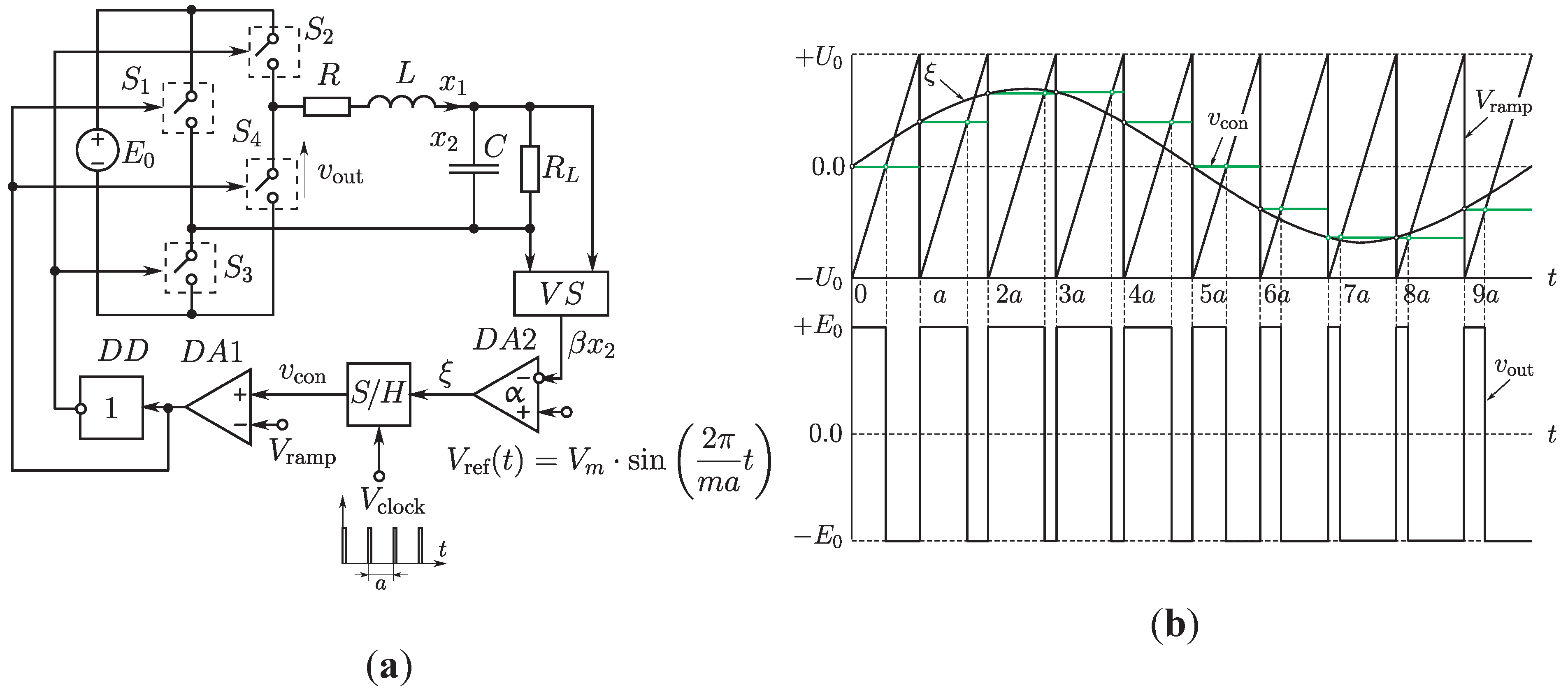
4.1. Power-Electronic DC/DC Converter with Multilevel Control

In order to study the dynamics of a pulse-modulated control system operating in the regime of high feedback gain, let us consider the multilevel DC/DC converter sketched in Figure 15a. Here, N is the number of input levels for the voltage supply, and E 0 denotes the highest available input voltage. In the following calculations we shall take the number of levels to be N = 3 .
Considering the control diagram in Figure 15a, E r is the output voltage, L the inductance of the filter coil, and R the associated loss resistance. C S is the current sensor, β its sensitivity, and V ref the reference voltage. R 0 and C 0 are components of the corrector circuit, D A 0 the corrector amplifier, and α the corrector gain factor. S / H is a sample-and-hold unit that reads the error signal α x 2 at every clock time and maintains it for the following switching period. Finally the comparators D A s , s = 1 , 2 , . . . , N compare the output signal from the sample-and-hold unit with the sawtooth signals V ramp ( s ) , s = 1 , 2 , . . . , N in order to generate the control signals to the switches S 1 , S 2 , ... , S N .
For a three-level system, the feedback control is implemented by means of three ramp functions such that V ramp ( 1 ) varies from 0 to U 0 / 3 , V ramp ( 2 ) between U 0 / 3 and 2 U 0 / 3 , and V ramp ( 3 ) between 2 U 0 / 3 and U 0 . All three ramp functions are driven by the same clock. Figure 15b illustrates the generation of the switching signals. At the beginning of each ramp cycle, the sample-and-hold unit reads the corrector output signal α x 2 and maintains this value for the entire ramp cycle. The output voltage from the sample-and-hold unit is denoted v con . As long as the value of v con (the control signal) falls in the interval from 0 to U 0 / 3 (the first zone), it is compared with V ramp ( 1 ) . If v con exceeds V ramp ( 1 ) , the switch S 1 is connected to the input voltage E 0 / 3 , and the connection is broken as soon as V ramp ( 1 ) becomes larger than v con . A similar scheme is applied if v con falls in one of the other zones.
Figure 15. (a) Schematic diagram of the considered DC/DC converter. E 0 is the maximum available input voltage and N the number of input levels. E r is the output voltage and V ref the reference voltage. C S is the current sensor, R 0 , C 0 and D A 0 are components of the feedback control, and S / H a sample-and-hold unit that generates the control signal to the comparators D A 1 , D A 2 , ..., D A N ; (b) Temporal variation of the control signal to illustrate the generation of the switching signals. v con is the output signal from the sample-and-hold unit and V ramp ( s ) , s = 1 , 2 , . . . , N are the ramp signals for the three different zones.
Electronics 02 00113 g015
The dynamics of the three-level converter system may be represented by the following set of two-coupled non-autonomous differential equations with discontinuous right hand sides:
x ˙ = λ 1 x + γ ( Ω m K F - Ω r ) and y ˙ = - x + λ 2 y + 1
where the (dimensionless) dynamic variables x and y represent, respectively, the normalized load current x 1 and the error signal x 2 of the integrating feedback corrector. Ω m and Ω r are the normalized input and output voltages, and λ 1 and λ 2 are the normalized eigenvalues for the linear dynamics that take place between the switching events. Note, that both λ 1 and λ 2 are negative.
K F = s = 1 N K F ( s )
with
K F ( s ) = 1 2 N 1 + sign ξ s , ξ s = y ( τ ) + η s ( t ) η s ( t ) = V ramp α λ 2 V ref = q N α λ 2 s - 1 + t - τ
is the switching signal. As before, N denotes the number of zones and α the corrector amplification factor. The parameter q controls the amplitude of the sawtooth functions. Finally, the applied normalization conditions are
x = β x 1 V ref , y = - x 2 λ 2 V ref , λ 1 = - a R L , λ 2 = - a C 0 R 0 γ = a β L , Ω m = E 0 V ref , Ω r = E r V ref , and q = U 0 V ref
where a is the period of the ramp signal and V ref the reference voltage.
The dimensionless time variable t is also normalized in the terms of the period of the ramp signal. The sawtooth functions η s ( t ) , s = 1 , 2 , . . . , N are periodically repeated normalized ramp functions with the ramp period 1, i.e., η s ( t + 1 ) η s ( t ) . The parameter q controls the amplitude of the sawtooth functions. τ = [ t ] = k - 1 , k = 1 , 2 , . . . is the discrete time variable, [ t ] being defined as a function that is equal to the integer value of its argument. The function y ( τ ) thus represents the error signal of the integrating feedback corrector at the beginning of each ramp cycle.
In the following bifurcation analysis we shall consider the corrector gain factor α and normalized output voltage Ω r as a control parameters. The remaining parameters have been chosen to be E 0 = 100 V, R = 0 . 083 Ω, L = 0 . 0106 H, U 0 = 10 V, V ref = 5 V, β = 0 . 1 Ω, a = 2 · 10 - 3 s, C 0 R 0 = 10 - 2 s, N = 3 .
During a given ramp period k - 1 < t < k , k = 1 , 2 , , all switching events take place within the same zone. In the intervals k - 1 < t < t k and t k < t < k between the switching times k - 1 , t k and k, the system is linear. By integrating the equations of motion for the continuous-time system (16) from switching event to switching event, our investigation can thus be reduced to an analysis of the two-dimensional piecewise-smooth map:
x k = e λ 1 ( x k - 1 + ϑ k + ) + λ 2 μ e λ 1 ( 1 - z k ) - ϑ k - y k = e λ 1 - e λ 2 λ 2 - λ 1 ( x k - 1 + ϑ k + ) + e λ 2 ( y k - 1 + θ k + ) + μ λ 2 e λ 1 ( 1 - z k ) - λ 1 e λ 2 ( 1 - z k ) λ 2 - λ 1 - θ k -
Here, x k and y k denote the value of the dynamic variables x and y at the switching time k and
ϑ k + = γ λ 1 s k N Ω m - Ω r ϑ k - = γ λ 1 s k - 1 N Ω m - Ω r θ k ± = ϑ k ± + 1 λ 2 ; μ = γ Ω m N λ 1 λ 2
The integer s k represents the zone in which the switching in the kth ramp cycle takes places, and the variable z k represents the relative pulse duration in the kth ramp cycle: z k = t k - k + 1 , 0 z k 1 . These variables are determined by:
z k = 0 , y k - 1 < 0 1 , y k - 1 > - q α λ 2 - N α λ 2 q y k - 1 - s k + 1 , 0 y k - 1 - q α λ 2
and
s k = 1 , y k - 1 < 0 N , y k - 1 > - q α λ 2 - N α λ 2 q y k - 1 + 1 , 0 y k - 1 - q α λ 2
where - N α λ 2 q y k - 1 again is defined as a function that is equal to the integer value of its argument. Expressed in terms of the value of the normalized error signal, the boundaries between the various zones are given by y = - q s N α λ 2 , s = 0 , N ¯ .

4.2. Chart of Dynamical Modes
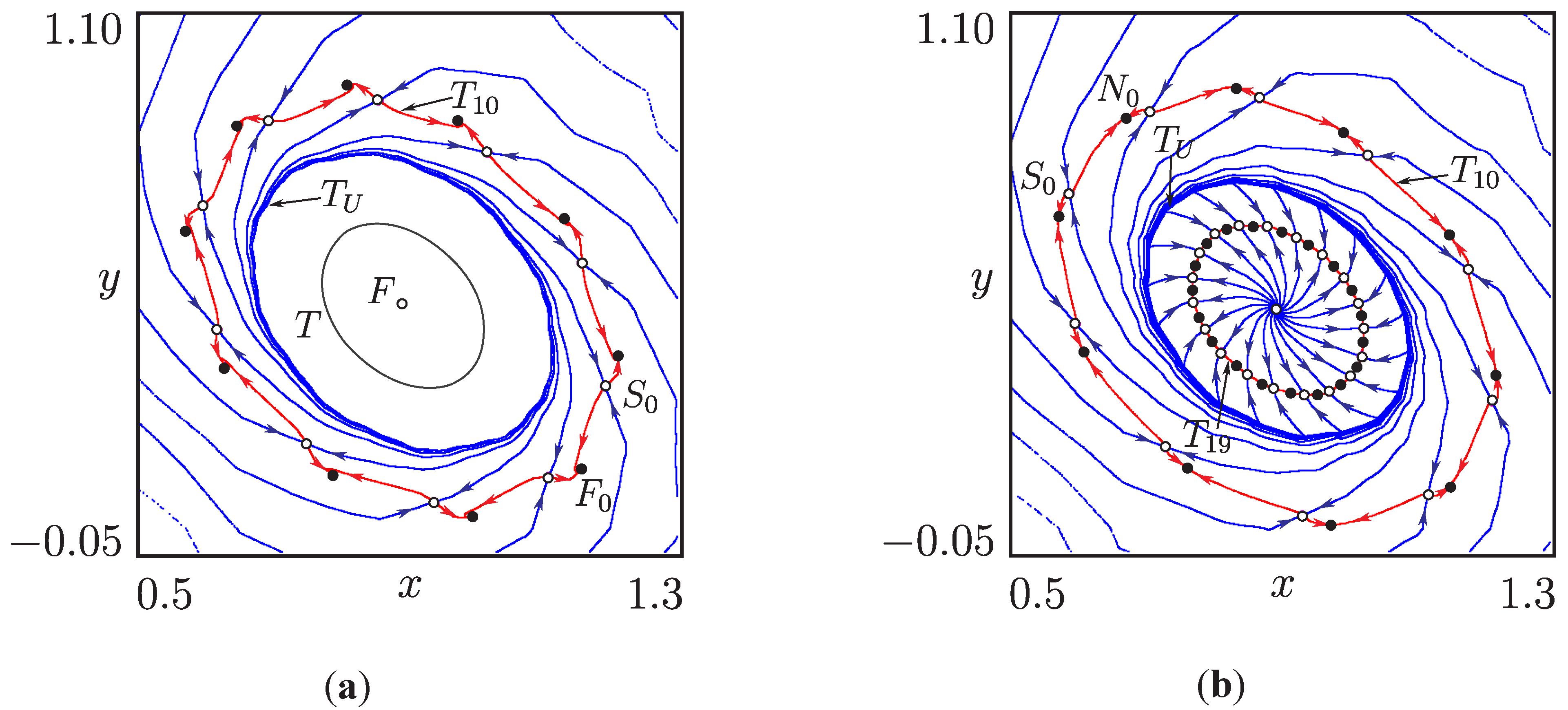
Figure 16 provides an overview of the distribution of dynamical modes (i.e., steady state solutions to the equations of motion) in the ( α , Ω r ) -plane. We recall that α is the corrector gain factor and Ω r the normalized output voltage. As mentioned above, the figure considers a part of parameter space where the corrector gain factor is relatively high ( α > 5 . 0 ). This implies that the converter is operating in a regime where instabilities are likely to arise. The purpose of our investigation is to examine a number of new transitions that lead to the formation of resonant or ergodic tori. We will only consider situations in which the required output voltage falls below the maximum available voltage. In the opposite case, the switching process will be abolished, and the converter will display a stable equilibrium point.
The light blue domains denoted Π 1 , 1 , Π 1 , 2 and Π 1 , 3 represent operational regimes where the converter displays stable, regular switching cycles. These are the normal operational modes, and for sufficiently low values of the corrector gain factor, they are stable node cycles. However, in the part of parameter space we consider here they are of stable focus type. This implies that they have damped oscillatory transients controlled by complex conjugate eigenvalues with numerical values less than 1. The three domains correspond to the three levels of input voltage.
In the domain Π 1 , 1 , the normalized output voltage Ω r is relatively small and the converter can provide the required voltage through operation in the first zone, v con < U 0 / 3 . In the domain Π 1 , 2 , the system operates in the second zone, and for higher load voltages (in the domain Π 1 , 3 ), the converter operates in the third zone. The transition from one zone to the next involves a border-collision bifurcation, either at the curve N φ , 1 C or at N φ , 2 C . At low values of the corrector gain factor (to the left of the points P 1 and P 2 ), this bifurcation takes form of a transition from one stable focus cycle to another. To the right of these points, the bifurcation involves the transition from a stable focus cycle (in the light blue region) to an ergodic or resonant torus (in the dark blue regions).
Figure 16. Chart of dynamical modes in the ( α , Ω r ) parameter plane. α is the corrector gain factor and Ω r is the normalized output voltage. The light blue regions represent stable periodic switching dynamics associated with operation at each of the three levels for the input voltage. The dark blue regions represent 2 D torus dynamics with their characteristic necklace formed resonance zones. For gain factors exceeding α 11 , this relatively simple structure is overshadowed by a more complex structure of coexisting modes. This is the region of concern to the present discussion.
Electronics 02 00113 g016
The curves N φ 1 , N φ 2 and N φ 3 are Andronov–Hopf (or Neimark–Sacker) bifurcation curves in which the stable period-1 solutions lose their stability and transform into closed invariant curves as the pair of complex conjugate eigenvalues continuously cross out through the unit circle in the complex plane. Above these curves the converter displays ergodic dynamics (i.e., quasiperiodicity) intervened by an infinite number of domains where resonant dynamics occurs. The transition to torus dynamics may be explained by the fact that the increasing feedback gain generates additional oscillatory modes in the system [85]. In Figure 16, the quasiperiodic (or non-resonant) dynamics is found in the dark blue areas of Π 1 , Π 2 , Π 3 , and the two-mode resonant dynamics is observed in the colored structures that run across these domains. As discussed in Section 2 and Section 3, the sausages-on-a-string shape of these structures is a characteristic feature of non-smooth systems where the resonance zones are delineated by border-collision fold bifurcations.
For α > 11 , the chart of dynamical modes display an even more complicated structure. The corrector gain is now so high that new tori begin to appear both around the stable focus point and around the already existing torus, and a variety of new bifurcation phenomena start to take place. Description of some of these phenomena will be the subject of the following sections.

4.3. Embedded Tori

In order to provide a clearer picture of what happens as the corrector gain factor crosses the critical value of about α 10 . 86 , Figure 17 displays a series of three one-dimensional bifurcation diagrams obtained as vertical scans through the bifurcation structure in Figure 16 for different values of α. In Figure 17a, α = 10 . 6 and the scan is performed in the relatively quiet regime below the appearance of coexisting structures. We recognize the two regions of torus dynamics extending, respectively from the point of Neimark–Sacker bifurcation at Ω φ 1 to the point of border-collision torus birth bifurcation Ω φ , 1 C and from Ω φ 2 to Ω φ , 2 C . All four torus birth bifurcations are supercritical, and we can observe both the relative abrupt transition in the growth of the torus amplitude associated with the modified Neimark–Sacker bifurcation and the nearly linear growth of the torus amplitude associated with the border-collision torus birth bifurcation.
Figure 17. (a) Bifurcation diagram for α = 10 . 6 illustrating the primary torus birth processes. Ω φ 1 and Ω φ 2 denote modified Neimark–Sacker bifurcations and Ω φ , 1 C and Ω φ , 2 C denote border-collision torus birth processes. Horizontal lines represent zone boundaries, and the green line represents the stable fixed point; (b) Formation of a large amplitude torus in the region between the primary tori, α = 11 . 0 ; (c) Formation of a new large amplitude torus around the primary torus, α = 11 . 6 .
Electronics 02 00113 g017
In Figure 17b, α = 11 . 0 and a new interval of torus dynamics has appeared between the border-collision bifurcation at Ω φ , 1 C and the Neimark–Sacker bifurcation at Ω φ 2 . We notice, however, that the period-1 focus cycle (fixed point of the map (19)) remains stable in this interval. This implies that the new torus cannot have been born through any of the above torus-birth processes. A further possibility is that the new torus has been born through a torus fold bifurcation, i.e., that a pair of stable and unstable tori of finite amplitude has been formed. As a first approach to examine this possibility, we have determined the basins of attraction for the coexisting stable solutions and found that the stable fixed point retains a relatively large basin of attraction throughout the entire interval of coexistence.
Finally, for α = 11 . 6 (see Figure 17c), a new torus structure has also appeared around the original torus in part of the interval between Ω φ 2 and Ω φ , 2 C . This new torus displays resonant period-10 oscillations over a relatively large range of Ω r -values. We also note that the emergence of this new torus does not affect the stability of the original torus.
Figure 18. (a) The large amplitude tori T 2 and T 3 , born in torus fold bifurcations, coexist, respectively, with the stable fixed point and with the original small amplitude torus T 4 . α = 11 . 83 ; (b) and (c) Expanding regions of existence for the various tori leads to merging processes.
Electronics 02 00113 g018
Figure 18 illustrates the changes in the bifurcation diagram that occurs as the corrector gain is further increased. In Figure 18a, α = 11 . 83 and the two large amplitude tori have spread along the Ω r -axis such that they almost touch both at the border-collision bifurcation Ω φ , 1 C and near the Neimark–Sacker bifurcation point Ω φ 2 . Inspection of the figure also shows that a similar large amplitude torus exists in the interval above the border-collision bifurcation point Ω φ , 2 C .
In Figure 18b, α = 11 . 85 and a merger has occurred among the two large-amplitude tori near the Neimark–Sacker bifurcation point Ω φ 2 . In Figure 18c, α = 11 . 885 and an overlap has also developed between the large amplitude torus and original torus at the border-collision bifurcation point Ω φ , 1 C .
We shall discuss the bifurcations associated with these processes in the next section. First, however, let us consider the torus cross sections depicted in Figure 19. In Figure 19a, α = 11 . 885 , Ω r = 10 . 7 , and the system operates in the region of period-10 resonance for the large amplitude torus. Here we observe an unstable fixed point of focus types F surrounded by an attracting ergodic torus T representing the small amplitude torus that exists between the Neimark–Sacker bifurcation at Ω φ 2 and the border-collision torus-birth bifurcation at Ω φ , 2 C . The ergodic torus T is again surrounded by the repelling torus T U 1 and, with an even larger amplitude we find the period-10 resonance torus T 10 with its saddle cycle S 0 and stable focus cycle F 0 . T U 1 represents the border between the basins of attraction for T and T 10 .
In Figure 19b, α = 12 . 36 and Ω r = 10 . 77 . Here, the system has moved into a region of resonance dynamics for the small amplitude torus, and we can observe the coexistence of stable period-10 and period-19 dynamics. The repelling torus T U 1 still serves as boundary between the two basins of attraction.
Figure 19. (a) Coexistence of a stable period-10 resonance torus T 10 and an attracting ergodic torus T. α = 11 . 885 and Ω r = 10 . 7 ; (b) Coexistence of stable period-10 and period-19 resonance dynamics. α = 12 . 36 and Ω r = 10 . 77 . In both figures, the unstable torus T U 1 separates the basins of attraction of the coexisting stable motions.
Electronics 02 00113 g019

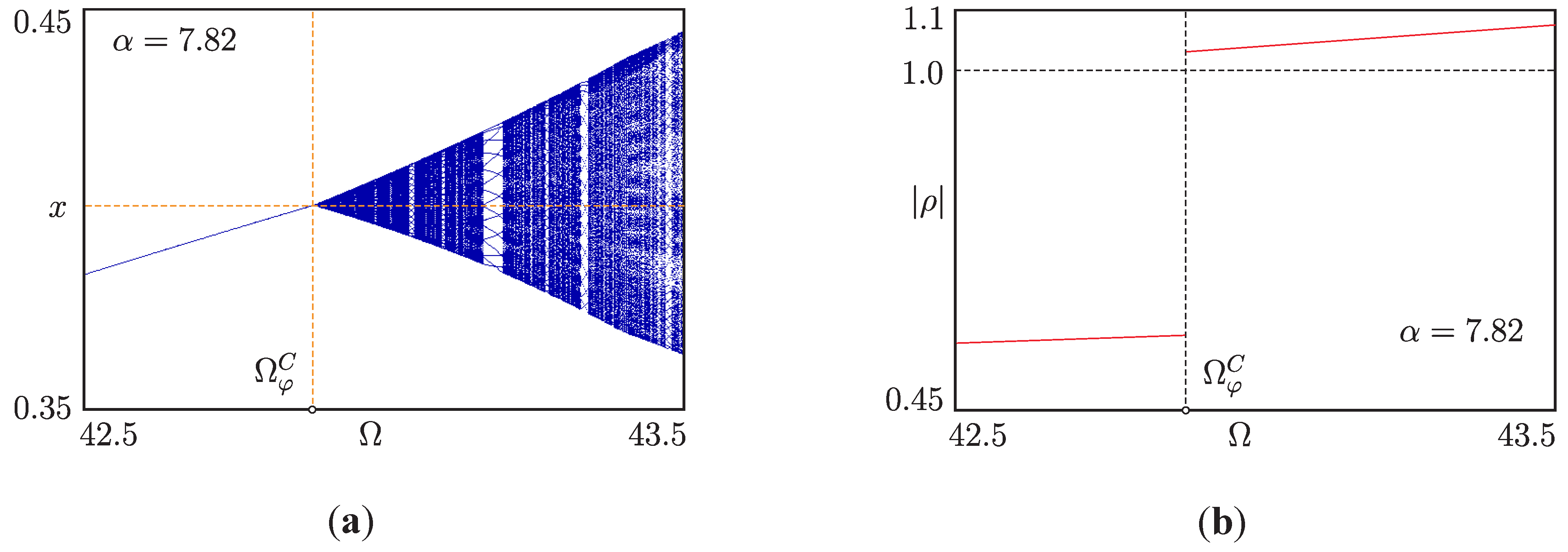
4.4. Torus Merging Processes

The purpose of this section is to provide an overview of some of the torus merging and reconstruction processes that occur as the output voltage is further increased. Figure 20a shows a bifurcation diagram for the transitions that occur near the Neimark–Sacker bifurcation point Ω φ 2 for α = 11 . 885 , i.e., within the rectangle denoted A in Figure 18c. We first notice that the size of the large amplitude torus passes smoothly across Ω φ 2 . The merger between the two parts of this torus that exist for α = 11 . 825 (Figure 18a) has already occurred in Figure 18b. This merger has involved the collision of a pair of stable and unstable tori from both sides and the reconstruction of the torus fold structures into an outer stable torus that connects smoothly across the Neimark–Sacker bifurcation point. The inner unstable tori are broken up into T U 1 and T U 2 .
Figure 20. (a) Close-up of the bifurcations that take place near the Neimark–Sacker bifurcation point Ω φ 2 (outlined by the rectangle A in Figure 18c). Note particularly the border-collision torus-fold bifurcation at Ω F C in which T 0 and T U 2 collide; (b) Phase diagram illustrating the different tori that exist for Ω r = 9 . 322 . The colored regions here represent the basins of attraction for the three coexisting stable tori.
Electronics 02 00113 g020
At the point of Neimark–Sacker bifurcation Ω φ 2 we observe the birth of the small amplitude torus T 0 and the associated destabilization of the fixed point. For increasing values of Ω r , the amplitude of T 0 increases in a parabolic manner until at Ω F C , the torus collides with the zone boundaries at y = - q 3 α λ 2 and y = - 2 q 3 α λ 2 . In this collision the torus undergoes a border-collision fold bifurcation, i.e., it disappears at the zone boundary after collision with the repelling torus T U 2 that spreads in from the neighboring zones. At the point Ω F , slightly to the right of the Neimark–Sacker bifurcation point we observe the formation of a third torus T of intermediate amplitude corresponding to the torus called T 4 in Figure 18a. This again involves a torus-fold bifurcation, although not of border-collision type. In the range between the torus-fold bifurcation at Ω F and the border-collision torus-fold bifurcation Ω F C , the system thus displays three coexisting stable tori, with their basins of attraction separated by the two unstable tori. Figure 20b shows a phase diagram for the Ω r = 9 . 322 . Starting with the focus point F that represents the, now unstable, basic operational mode, we first observe the stable ergodic torus T 0 . Thereafter follow the unstable torus T U 2 that delineates the basin of attraction for T 0 , the stable ergodic torus T, the unstable torus T U 1 and, finally, the large amplitude resonance torus T S represented by its stable period-97 node solution.
Figure 21 provides an overview of the total bifurcation structure for a value α = 11 . 885 of the corrector gain factor. To the left in the figure, the large amplitude torus T S already exists together with the unstable torus T U 2 . These tori have been formed at lower output voltages through processes similar to those we observe to the left in Figure 21. As the required output voltage Ω r increases, the structural change to first occur is the birth of the small amplitude torus T 0 in a supercritical Neimark–Sacker bifurcation at Ω φ 2 . This bifurcation leaves the fixed point, i.e., the basic operational mode, unstable. In the left hand side of the picture, the small amplitude torus T 0 again disappears through collision with T U 2 in a border-collision torus-fold bifurcation at Ω F C . In the mean time, the stable torus T of intermediate amplitude has been born together with the unstable torus T U 1 in a torus fold bifurcation at Ω F (still to the left in the figure). This pair of tori continues to exist until they finally disappear in the border-collision torus-fold bifurcation Ω F C to the far right in the figure. At this voltage, the original large amplitude torus T S has been destroyed in a homoclinic bifurcation at Ω H , producing the stable period-10 focus cycle F 0 , and a new large amplitude stable torus T S has been born at the homoclinic bifurcation Ω H to the right in the diagram. The basins of attraction for F 0 and the large amplitude stable torus T S are delineated by the stable manifolds of the period-10 saddle cycle.
Figure 21. Sketch of the overall bifurcation structure for α = 11 . 885 . The diagram illustrates the formation and termination of coexisting stable and unstable tori in the dynamics of the converter system. The observed bifurcations include modified (non-smooth) torus-birth and torus-fold bifurcations (denoted Ω φ 2 and Ω F , respectively), homoclinic bifurcations ( Ω H ), as well as border-collision torus-fold ( Ω F C ) and supercritical border-collision torus-birth bifurcations ( Ω φ , 2 C ).
Electronics 02 00113 g021
Moreover, a new pair of stable and unstable tori, T S 2 and T U 2 , has been born in the torus fold bifurcation Ω F . As the parameter Ω r passes the value Ω φ , 2 C , the unstable focus fixed point F undergoes a reverse supercritical border-collision torus-birth bifurcation. As result, a stable ergodic torus T S 2 merges with the fixed point F. When this happens, the unstable focus fixed point F turns into the stable focus F (i.e., the fixed point F is stable to the right of the bifurcation point Ω φ , 2 C in Figure 21).

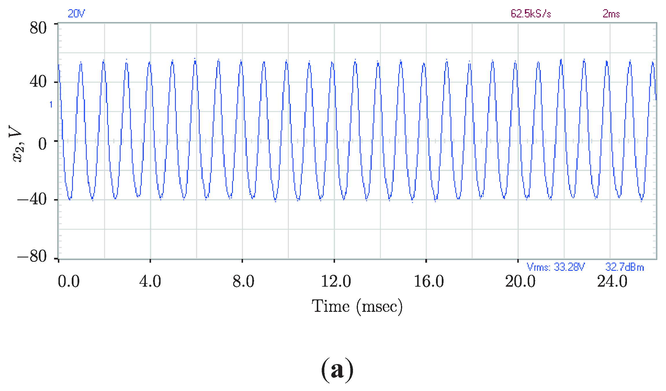
4.5. Behavioral Complexity of the Multilevel DC/DC Converter

This section has presented an overview of the main torus formation and reconstruction processes that one can observe in a typical DC/DC converter with multilevel control when operating in a regime of high corrector feedback gain. As previously noted, the advantage of using relatively high gain factors is that a specified variation in the output voltage can be followed faster and more precisely. However, as our investigations have shown, this happens at the risk not only of destabilizing the basic modes of operation, but also of introducing new quasiperiodic and resonant periodic modes to the system, including modes whose formation cannot be predicted from a stability analysis of the basic modes.
With multilevel control, the converter displays different zones of operation corresponding to the different levels of input voltage. At normal corrector feedback gains, the basic operational modes are of stable node or focus type, and transitions from one mode to another in response to variations in the required output voltage take place via border-collision bifurcations at the zone boundaries. As the feedback gain is increased regions of parameter space starts to arise where the normal operational modes have lost their stability and been replaced by quasiperiodic or resonant periodic dynamics on invariant tori. At each of the zone boundaries, this transition takes place through a border collision torus-birth bifurcation in which a pair of complex conjugated eigenvalues jumps across the unit circle in the complex plane. In this way, regions of torus dynamics arise at the upper end of each of the operational regions. For lower values of the output voltage, these ranges of torus dynamics terminate in non-smooth Neimark–Sacker bifurcations. Such non-smooth Neimark–Sacker bifurcations distinguish themselves from normal Neimark–Sacker bifurcations by not showing a parabolic growth in amplitude for the emerging mode.
As the feedback gain is further increased, a multitude of new modes arise and coexist with the already described modes. This has lead us to examine a number of unusual bifurcation phenomena, including (i) subcritical border-collision torus birth processes in which an unstable torus collapses onto a stable periodic orbit and transforms it into an unstable cycle; (ii) border-collision torus-fold bifurcations in which a pair of stable and unstable tori meet and annihilate at the boundary of two operational zones; and (iii) torus reconstruction processes in which pairs of stable and unstable tori from either side of a zone boundary collide and the stable and the unstable tori hereafter continue smoothly across the zone boundaries.
It is unlikely that DC/DC converters deliberately will be designed to operate in the regime of torus dynamics. However, as experience shows, the parameters and working conditions of a given converter may gradually shift with time, and the converter may start to operate in regions that have not be considered in its design. Considering the rapid growth that the use of converter systems has undergone during the last few decades, and the enormous significance that converters are destined to have in the realization of a so-called “smart” power distribution system, it is obviously in line with usual engineering practice to carefully investigate what happens outside the normal operational regime. Experimentally, operation outside the normal regimen is also realizable [43]. Such operation is found first of all to reduce the efficiency of the conversion process. However, the loss of energy associated with this loss of efficiency might cause the temperature of the converter to rise and thereby influence a large number of other parameters of significance for the functioning of the system.

5. Single-Phase Pulse-Width Modulated H-Bridge Inverter

We have already listed several important applications for the inverter (or DC/AC converter). Industrial uses of this type of converter also include its application to supply AC power of variable frequency and voltage to induction furnaces. By virtue of their clean operation, easy regulation and high energy efficiency, induction furnaces have gradually penetrated the metal-melting industry from the melting of gold, copper and aluminum to the melting of steel and iron. Via the skin depth of the material, the optimal frequency depends on the type of metal to be melted and the size of the load. Operational frequencies for the power supply may thus vary from 50 Hz to hundreds of kHz.
The purpose of this section is to illustrate the transitions from regular periodic operation to quasiperiodicity and high-periodic resonance dynamics that one can observe in pulse-width modulated inverter systems. As in the previous sections, the focus will be on inverters that operate with high corrector gain. We will demonstrate how the transition to quasiperiodicity may occur either via a modified Andronov–Hopf bifurcation or via a border-collision torus-birth bifurcation. Phase portraits will be presented in order to demonstrate the phenomenon of phase-synchronized quasiperiodicity, and the numerically calculated waveforms will be compared with experimental results for an inverter with similar parameter values.
Phase-synchronized quasiperiodicity denotes an interesting form of synchronization in which a quasiperiodic system adjusts its dynamics in response to an external periodic forcing, the appearance of a new oscillatory mode in the system, or the interaction with another quasiperiodic oscillator. This type of dynamics appears first to have been described by Postnov et al. [86] and by Anishchenko et al. [87] who identified the phenomenon as winding number locking on a two-dimensional torus. Similar phenomena have been described by Loose et al. [88] who performed experimental studies of quasiperiodic synchronization for a system of interacting semiconductor lasers, and by Giaouris et al. [89] who examined torus-torus interaction and the onset of three-frequency quasiperiodicity in a current mode controlled boost converter.
Phase synchronized quasiperiodicity manifests itself in the form, for instance, of stable quasiperiodic motions with three independent frequencies of which two remain unsynchronized while the third component synchronizes with one of the former. For our DC/AC converter we shall demonstrate numerically as well as experimentally how the amplitude of the quasiperiodic oscillations that arise through a torus-birth bifurcation from the main switching cycle is modulated by the period of the reference signal. In this case, the switching cycle is synchronized with the reference signal, but the oscillatory component produced in the torus-birth bifurcation may remain unsynchronized.

5.1. Model of the Single Phase PWM H-Bridge Inverter

Figure 22 presents the outlay of the considered single phase PWM H-bridge inverter and Figure 23 shows the corresponding schematic circuit diagram. Inspection of Figure 22 allows us to identify the input filter (1), the four switches (2), and the components of the L C -filter (3). We can also locate the sample-and-hold unit S / H (4), the error amplifier D A 2 (5), and the sine-wave generator (6). The remaining components are the current protection circuit (7), the MOSFET drivers (8), the inverter D D (9), and the comparator D A 1 (10). Finally (11) and (12) are the ramp and clock pulse generators, respectively.
Figure 22. Experimental setup of a single phase PWM H-bridge inverter. (1) is the input filter; and (2) locates the four switches realized by means of metal-oxide-semiconductor field-effect transistors; (3) is the output L C filter; (4) and (5) are the sample-and-hold unit S / H and the error amplifier D A 2 ; (6) is the DDS (Direct Digital Synthesis) sine wave V ref ( t ) generator; (7) the current protection circuit; (8) the MOSFET drivers; and (9) the logic inverter D D .
Electronics 02 00113 g022
The switches S 1 , S 2 , S 3 and S 4 play an essential role for the operation of the converter. They may be realized, for instance, by means of metal-oxide-semiconductor field-effect transistors (MOSFET). The four switches operate in pairs such that S 1 and S 4 switch synchronously and S 2 and S 3 switch together, but in anti-phase with S 1 and S 4 . The states of the switches define two distinct topologies of the inverter: T 1 ( S 1 , S 4 on and S 2 , S 3 off) and T 2 ( S 1 , S 4 off and S 2 , S 3 on). These topologies provide opposite voltages to the load. When the switches S 2 and S 3 are on and S 1 , S 4 are off, a positive voltage E 0 will be applied to the L C filter. When S 2 , S 3 are off and S 1 , S 4 are on, this voltage is reversed.
The switches are operated by the sinusoidal PWM modulator. In this way the switching process is controlled through a feedback mechanism. A simple method, called voltage-mode control, implies that a voltage proportional to the A C output voltage is compared with a reference sinusoidal voltage V ref ( t ) of frequency f ref = 1 / T , T = m a , to generate a control voltage v c o n (modulating signal). Here, a denotes the ramp period and m is referred to as the frequency modulation ratio. The control signal is then compared with a sawtooth waveform V ramp to generate the switching signal. The switches S 1 , S 4 are tuned on and S 2 , S 3 are turned off at the beginning of each ramp period a, and switches S 1 , S 4 are tuned off and S 2 , S 3 are turned on when the ramp voltage exceeds the value of the control voltage at the beginning of the ramp cycle.
Figure 23. Schematic diagram of the PWM H-bridge single phase inverter. E 0 is the external supply voltage and x 2 the output voltage. V ref ( t ) is the sinusoidal reference voltage with the period T = m a and ξ = α ( V ref ( t ) - β x 2 ) is the error signal. The sample-and-hold unit S / H detects the error signal ξ at the beginning of each clock time. This produces the signal v con that together with the ramp function V ramp generates the switching signals to the switches S 1 , S 4 , and S 2 , S 3 ; (b) As long as v con > V ramp , switches S 1 , S 4 are on and S 2 , S 3 are off, while S 1 , S 4 are off and S 2 , S 3 on for v con < V ramp .
Electronics 02 00113 g023
Considering again the schematic diagram in Figure 23, L and C denote, respectively, the inductance and the capacitance, of the L C filter, R L is the load resistance, and R is a parasitic resistance characterizing the dissipation in the inductance coil. x 1 represents the current in the filter inductance L and x 2 the output voltage. V S is the voltage sensor, β its sensitivity, and V ref ( t ) the reference voltage at frequency f ref . D A 2 is the corrector amplifier, α the corrector gain factor, and S / H a sample-and-hold unit that reads the error signal α ( V ref ( t ) - β x 2 ) at every clock time and maintains it for the following switching period. Finally the comparator D A 1 compares the output signal from the sample-and-hold unit with the sawtooth ramp signal V ramp ( t ) , in order to generate the control signals to the switches S 1 , S 2 , S 3 , S 4 . For a PWM H-bridge single phase inverter, the feedback control is implemented by the ramp function such that V ramp ( t ) varies from - U 0 to + U 0 .
The dynamics of the single phase PWM H-bridge inverter may be represented by the following set of two-coupled non-autonomous differential equations with discontinuous right hand sides:
x ˙ = μ x - ω y - ( μ - ω ) K F ; y ˙ = ω x + μ y - ( μ + ω ) K F
Here
K F = sign ( ψ - η ) , ψ = q Ω sin 2 π τ m - ϑ x ( τ ) - y ( τ ) η = 2 P α Ω [ t * - τ - 1 / 2 ] ; t * = t / a ; τ = [ t * ] ϑ = μ + ω μ - ω ; P = U 0 β E * ( 1 - ϑ ) ( 1 + R / R L ) q = V m U 0 P ; Ω = E 0 / E *
with
μ = - a 2 R L + 1 C R L and ω = a 1 L C 1 + R R L - 1 4 R L + 1 C R L 2 > 0
The (dimensionless) dynamic variables x and y are linear combinations of the current x 1 and output voltage x 2 :
x 1 = - ( R / L + μ / a ) w 1 - ω w 2 / a ; x 2 = w 1 / C w 1 = - a 2 E 0 2 ω L ( μ 2 + ω 2 ) { ( μ + ω ) x - ( μ - ω ) y } w 2 = - a 2 E 0 2 ω L ( μ 2 + ω 2 ) { ( μ - ω ) x + ( μ + ω ) y }
Together the two variables x and y represent the smooth dynamics of the system, and all other processes are assumed to be instantaneous. In particular, the switches in the H-bridge are assumed to function ideally. μ and ω are the real and imaginary parts of the eigenvalues of the system matrix, normalized relative to the period a of the ramp signal. The sawtooth function η is periodically repeated ramp function with the ramp period 1, i.e., η ( t * + 1 ) η ( t * ) with t * = t / a . τ = [ t * ] = k - 1 , k = 1 , 2 , . . . being the normalized discrete time variable. As in the previous section, [ t * ] denotes the integer value of t * . The parameter P controls the amplitude of the ramp functions and q represents the amplitude of the reference voltage.
In our numerical calculations we have used R = 1 . 0 Ω; L = 4 . 0 · 10 - 3 H; C = 3 . 5 · 10 - 6 F; R L = 45 Ω; V m = 4 V; U 0 = 10 V; α > 0 and E 0 > 20 V. These parameter values correspond to the values of the experimental converter system. Ω = E 0 / E * with E * = 1 V is the normalized input voltage. The gain factor α and the normalized input voltage Ω will be used as the main control parameters. However, other parameters such as the sensitivity β of the voltage sensor, the frequency modulation ratio m and the ramp period a may also vary from figure to figure. The values of these parameters will be specified in the captions of the various figures.
By integrating the equations of motion for the continuous-time system (18) ramp period by ramp period, our investigation is reduced to the analysis of the periodically forced piecewise-smooth map:
(19) x k = e μ cos ω · x k - 1 - sin ω · y k - 1 + 2 e μ ( 1 - z k ) cos θ k - sin θ k - 1 y k = e μ sin ω · x k - 1 + cos ω · y k - 1 + 2 e μ ( 1 - z k ) sin θ k + cos θ k - 1 k = 1 , 2 , .
Here θ k = ω ( 1 - z k ) and
z k = 0 , φ k - 1 < - P α Ω α Ω 2 P φ k - 1 + 1 2 , | φ k - 1 | P α Ω 1 , φ k - 1 > P α Ω
with
φ k - 1 = q Ω sin 2 π ( k - 1 ) m - ϑ x k - 1 - y k - 1
As in the previous section, the variable z k denotes the relative pulse duration in the kth ramp cycle. Besides quasiperiodic motion, the map (19) is found to generate a variety of resonance modes, including cycles of period T 0 = n T , n = 1 , 2 , . . . Here, T = m a denotes the period of the reference signal (the intended period of the output signal). We will refer to above type of resonance modes as a period-n cycles.

5.2. Torus-Birth Bifurcations

As long as the corrector gain factor α and the normalized input voltage Ω are sufficiently small, the inverter displays stable regular switching dynamics. The bifurcation diagram in Figure 24a illustrates the transition from this dynamics to quasiperiodicity (and various forms of high order resonance dynamics) that occurs as the gain factor (for relatively large values of the input voltage) increases beyond the normal operational regime. This transition takes place via an Andronov–Hopf bifurcation. As previously noted, this implies that a pair of complex-conjugated multipliers for the fixed point (period-1 cycle) smoothly crosses out of the unit circle. However, the form of the bifurcation diagram, particularly the non-parabolic growth of the quasiperiodic amplitude, reveals that the process takes place in a non-smooth system. Figure 24b shows the variation of the module of the two complex-conjugated multipliers across the bifurcation point.
Figure 24. Birth of a quasiperiodic orbit from a stable period-1 cycle in a Neimark–Sacker bifurcation; (b) Variation of the absolute value | ρ | of the complex-conjugate multipliers ρ 1 , 2 = ρ r ± j ρ j of the period-1 cycle. α φ is the bifurcation point for the Neimark–Sacker bifurcation. Ω = 44 . 0 , β = 0 . 075 , m = 10 and a = 10 - 4 s.
Electronics 02 00113 g024
Figure 25 shows the transition from stable period-1 dynamics to quasiperiodicity across a curve of border-collision torus-birth bifurcation. This transition is observed when the input voltage Ω (for relative large values of the corrector gain factor) exceeds the border of the normal regime of operation. The bifurcation diagram (Figure 25a) illustrates the linear growth of the quasiperiodic amplitude with the distance to the bifurcation point characteristic of border-collision bifurcations. As shown in Figure 25b, the complex-conjugated multipliers for the period-1 cycle undergo an abrupt jump as the system crosses the bifurcation point Ω φ .
Figure 25. (a) Birth of a quasiperiodic orbit from a stable period-1 cycle in a border-collision bifurcation; (b) Variation of the absolute value | ρ | of the complex-conjugate multipliers ρ 1 , 2 = ρ r ± j ρ j of the period-1 cycle. Ω φ C is the bifurcation point for the border-collision bifurcation. α = 7 . 82 , β = 0 . 075 , m = 10 and a = 10 - 4 s.
Electronics 02 00113 g025
The two different torus-birth processes are both related to the same underlying mechanisms, namely to the instability associated with the fact that the system operates with a relatively high corrector gain factor. However, the form of the transition depends on which branch of the bifurcation curve the system crosses, and so does the organization of the resonance regions in the quasiperiodic domain.
Figure 26 and Figure 27 illustrate the accordance we achieve between the experimentally observed and numerically calculated wave forms both for the region of stable period-1 dynamics (a) and for the quasiperiodic regime (b).
Figure 26. (a) Experimental observed wave form for the output voltage x 2 of the PWM H-bridge single phase inverter under regular periodic operation with an input voltage of E 0 = 44 . 0 V and with α = 7 . 0 , β = 0 . 075 , m = 10 and a = 10 - 4 s. Experimentally observed waveform for the output voltage x 2 after the transition to quasiperiodicity. The input voltage is now E 0 = 47 . 0 V, α = 7 . 6 , β = 0 . 075 , m = 10 and a = 10 - 4 s.
Electronics 02 00113 g026aElectronics 02 00113 g026b
Figure 27. (a) Numerical observed wave form for the output voltage x 2 of the single phase PWM H-bridge inverter under regular periodic operation with an input voltage of E 0 = 44 V, α = 7 . 0 , β = 0 . 075 , m = 10 and a = 10 - 4 s. Numerical observed waveform for the output voltage x 2 after the transition to quasiperiodicity. The input voltage is now E 0 = 47 . 0 V, α = 7 . 6 , β = 0 . 075 , m = 10 and a = 10 - 4 s.
Electronics 02 00113 g027

5.3. Phase Synchronized Quasiperiodicity

Figure 28 illustrates the transition from simple periodic dynamics to phase-synchronized quasiperiodicity. Figure 28a,b first shows the phase space trajectory and the waveform for the stable period-1 cycle that exists in the region with relatively low values of the corrector gain factor. The variables x and y are the state variables in our original time-continuous description of the inverter system Equation (18). The two curves have been calculated by iterating the periodically forced map in Equation (19) with a ramp period of a = 2 × 10 - 5 s and a frequency modulation ratio of m = 200 . The curves in Figure 28a,b thus contain 200 points per full cycle of the reference voltage V ref ( t ) .
Figure 28. (a), (b) Stable synchronous period-1 cycle. m = 200 , α = 20 , a = 2 × 10 - 5 s, and Ω = 60 . The phase portrait (a) is calculated by iterating the periodically forced map (19) and, corresponding to the value of frequency modulation ratio m, contains 200 points. The arrow indicates the direction of rotation. (c) The stable period-1 cycle undergoes a torus bifurcation at the point α = α φ ( α φ 21 . 509 ), producing a quasiperiodic dynamics that pulsates in synchrony with the reference voltage (d).
Electronics 02 00113 g028
Figure 28c shows the variation of the real and imaginary parts of the complex conjugated multipliers for the period-1 cycle with the corrector gain factor α. This variation displays an unusual oscillatory character that seems to continue with decreasing amplitude to the left of the figure as the corrector gain factor is reduced. However, as α reaches the Hopf bifurcation threshold α φ , the stable period-1 solution loses its stability and undergoes a torus-birth bifurcation (of modified Andronov–Hopf type). In Figure 28d this transformation manifests itself as a broadening of the original period-1 orbit as each point in Figure 28a is replaced by a small elliptic curve. Particularly interesting in the present context is the fact that this broadening is inhomogeneous and especially pronounced in the down strokes of the temporal variation of x (see Figure 28d).
Inspection of Figure 29 provides a clearer picture of the structure of the quasiperiodic phase space trajectory. Figure 29a shows the overall structure of this trajectory, and Figure 29a,b shows magnifications of, respectively, the broad down stroke and the much thinner upstroke. This is an example of phase-synchronized quasiperiodicity, i.e., a quasiperiodic attractor that is modulated by the presence of a third frequency, the frequency of the reference voltage V ref ( t ) .
Figure 29. (a) The phase portrait for the phase synchronized quasiperiodic mode that is calculated by the iterating of the periodically forced map (19). α = 21 . 523 , Ω = 60 and a = 2 × 10 - 5 s. This phase portrait contains m = 200 closed invariant curves, associated with the quasiperiodic solution. As illustrated in (b) and (c), the diameters of these closed curves vary periodically with the period T of the sinusoidal reference voltage V ref ( t ) , i.e., T = m a .
Electronics 02 00113 g029

5.4. Signal Distortion

The normal operational regime for the DC/AC converter discussed in this section is the regime of stable period-1 dynamics. In this regime, the quality of the output signal can be characterized by means of its Total Harmonic Distortion ( T H D ). This measure is defined as the ratio of the square root of the sum of the squares of all harmonic voltage components relative to the root mean square ( R M S ) voltage of the fundamental frequency, i.e.,
T H D = V 2 2 + V 3 2 + + V 2 V 1 · 100 %
where V i , i = 2 , . . . . is the root mean square ( R M S ) value of the i-th harmonic, and V 1 is the R M S value of the fundamental cycle. Total harmonic distortion will obviously vanish if there are no parasite harmonics. On the other hand, if the form of the output voltage differs significantly from the sine wave specified by the reference signal, T H D will be high.
We have determined the total harmonic distortion for the DC/AC converter model to be T H D = 2 . 83 % when the converter operates in its normal period-1 regime ( m = 200 , E 0 = 50 V, α = 6 . 0 , β = 0 . 075 , and a = 10 - 4 s). Note, however, that due to the assumption of ideal switching dynamics, only the ripple left unsmoothed by the output filter is included in the calculated value of T H D . Possible contributions from imperfect switching are neglected.
When the corrector feedback gain starts to exceed one of the torus bifurcation curves, the period-1 cycle loses its stability and variety of complex dynamical modes appear, including resonance cycles of different periodicity, quasiperiodicity, and phase synchronized quasiperiodicity. When such modes appear, the converter produces forms of distortion that can no longer be accounted for by the above index of total harmonic distortion.
To characterize the distortion of a complex output voltage with both anharmonic components and contributions with nearly continuous spectra, we have used an index of Complex Mode Distortion
C M D = V total 2 - V 1 2 V 1 · 100 %
with
V total = lim T s 1 T s 0 T s x 2 2 ( t ) d t
Here, V 1 is the R M S -voltage of the fundamental mode and V total is the R M S -value of the output voltage with its harmonic, subharmonic, resonant, and/or ergodic spectral components. T s is the averaging time. For a periodic output voltage, T s may be restricted to one period. For a quasiperiodic or chaotic output voltage, T s must be large enough to include low-frequency components in the output signal with sufficient accuracy. The index for complex mode distortion C M D reduces to the T H D if only harmonic distortion is present. Numerical calculations show that the distortion in the output signal from our H-bridge inverter system increases to about C M D = 17 . 0 % when the system displays phase-synchronized quasiperiodic motion (e.g., for m = 200 , E 0 = 50 V, β = 0 . 075 , a = 10 - 4 s, and α = 6 . 5 ).
The frequency modulation ratio m obviously has a major impact on the quality of the output signal (or on the requirements to the output filter). If the frequency modulation ratio is small, the parasite harmonics of the output voltage may interact with the fundamental frequency and destroy the linear relation between reference and output signals.

6. Conclusions and Perspectives

Pulse-width modulated converter systems have a broad and rapidly growing area of application. Over a few decades the use of DC/DC converters and other types of converter systems has spread from their initial application in space- and aircrafts [72] to the widespread use as power supplies in the industry and transportation sectors as well as in common household appliances.
By virtue of the complex set of requirements to their operation, it is not always easy to optimize the architecture of a converter system or to determine the best choice of parameters for a given application. Computer simulations therefore play an important role in the design of these systems. Besides its size, weight and cost, the most important performance parameters for a pulse-modulated power supply system are the conversion efficiency, the speed and accuracy of its regulation, and the noise (or signal distortion) it produces through its switching dynamics. A fourth important parameter is the safety margin in parameter space between the desired mode of operation and other modes that would reduce the performance significantly.
In the present review we have focused on the instabilities that can arise in DC/DC and DC/AC converter systems that operate with high feedback gain factors. Significant feedback gain is necessary to ensure a fast and precise regulation. However, for both types of converter systems we have shown experimentally as well as through computer simulation how a transition from stable regular switching dynamics to various forms of ergodic or resonant torus dynamics occurs if the feedback gain becomes too large. We have demonstrated that this transition can take place either via a modified Hopf bifurcation (in which a pair of complex conjugated eigenvalues smoothly move out of the unit circle in the complex plane) or through a border-collision torus-birth bifurcation (in which the eigenvalues jumps out of the unit circle). We have also shown that the torus-birth bifurcations may be subcritical. This usually implies that a pair of stable and unstable tori is born in a torus-fold bifurcation and that these tori coexist with the stable period-1 cycle over a certain parameter range. By further increasing the feedback gain we have observed a number of additional complex dynamical phenomena, including the formation of structures of embedded tori, torus-torus reconstruction, and the emergence of so-called phase synchronized quasiperiodicity.
Our analysis is based on the assumption that the switching processes are instantaneous and that the smooth dynamics of the converter systems is generated by the linear output filter. This has allowed us to analytically integrate the equations of motion from switching event to switching event and thereby reduce the mathematical model to a low-dimensional map. This approach provides an enormous simplification to the problem. At the same time, transformation of the system into a low-dimensional nonlinear map clearly emphasizes the role of border-collision bifurcations and other nonlinear dynamic phenomena.
An obvious way to reduce the noise in the output signal would be to adjust the parameters of the output filter, i.e., increase the capacitance C and/or the inductance L. However, this would in most cases add to the size and weight of the converter. An alternative approach would obviously be to increase the switching frequency, but it is also possible to experiment with the overall architecture of the converter, e.g., by introducing additional levels for the input voltage. A larger number of input levels generally allow the output voltage to be delivered with higher efficiency and less distortion. At the same time, a multi-level architecture reduces the requirements to the individual components.
The review has already mentioned a significant number of applications of power electronic converter systems ranging from power supplies in mobile phones, household appliances and navigation equipment for boats, cars, and airplanes, over back-up systems for sensitive computers and hospital equipment to power supplies for electric cars and induction furnaces. A characteristic feature of many of these applications is that the use of power electronic converters so to speak “unties” us from the main power distribution network and allows us to use electric power at places and under conditions where the main power lines are not directly accessible.
At the same time, power electronic converters (so-called grid-tie converters) have made it possible to feed electric power into the main distribution system from sources that do not operate with normal line voltage and frequency or cannot satisfy standard conditions with respect to regularity and stability. Solar cell panels, for instance, produce DC power at low voltages and high currents, and the availability often involve random variations at many different time scales. Similarly, the electric power output from a wind mill park lacks the regularity of voltage, frequency and phase required by the net. Realization of the so-called “smart grid” power distribution system that will allow us to replace contributions from major coal- and oil-fired power stations by inputs from large numbers of smaller and diffuse sources (beside solar cells and wind mills also local co-generation plants and plants operating on biogas, secondary biomaterials, waste, geothermal energy, etc.) will require an intelligent and closely supervised system. The smart grid system will also require a broad spectrum of different power electronic converters.
Conversion between AC and DC high voltage power already play an important role in the optimization and stabilization of the main distribution network. The need for this type of conversion arises, for instance, in connection with the transmission of high voltage power over long distances where the Ohmic losses in the transmission line become significant. Due to the skin effect, an AC current does not distribute itself uniformly across the conductor, thus causing increased losses. For transmission in underground or undersea cables, the capacitive current required to repeatedly charge the cable capacitance contribute additional losses not encountered with DC transmission. Finally, in relation to the dielectric breakdown of the insulation, DC-transmission also offers an advantage over AC transmission when compared at the same R M S -voltage.
Another important use of DC transmission is associated with the stabilization of the main distribution system. One way of achieving such stabilization involves a partial decoupling of different parts of the network such that they can operate at different phases and slightly different voltages and frequencies, but still exchange power in a controlled manner. This form of separation can be achieved by inserting DC transmission lines between the different parts of the networks with AC/DC and DC/AC converters in either end. Beside the costs of such high-power high-voltage converters, a main problem with this approach is clearly the additional structural complexity it introduces, and the associated need for new control approaches.
We hope that the analysis presented in this review can contribute to a better understanding of the relation between the architecture of a power electronic converter and the dynamics it will display under different operational conditions. Such understanding clearly represents an essential background for the design of new and improved converter systems.
During the last decades, development of the converter technology has to a significant extent been driven by improvements of the physical/electronic properties of the various components such as to allow for operation at higher voltages, powers, frequencies and/or efficiencies while at the same time minimizing size, failure rates, and costs. During the last few years, improvements in the converter technology have increasingly become dependent on an effective and intelligent, digital control of the way of operation. The appearance of microcomputers with sufficient computational capacity has lead to the development of new types of so-called predictive controllers. These controllers are capable of following variations in currents, voltages, on-times, efficiencies, etc., evaluate this information within a clock period, and trigger the next switching process to occur with an optimal timing [90,91,92]. The scope of this approach is even broader as it can be used to detect for reactive power [93], ground leakage [94], unusual temperature variations, and a broad range of other indications of inappropriate or non-optimal functioning. The digital control approaches will also come to play an extremely important role in connection with a realization of the smart-grid construct.

Acknowledgements

Zh. T. Zhusubaliyev acknowledges grants received from various Danish sources to allow him to visit the Department of Physics of the Technical University of Denmark.
The work was partially supported by the Federal Target Programme “Scientific and Pedagogical Personnel of Innovative Russia” for 2009-2013, Contract No. 14.B37.21.1146.

References

  1. Bose, B.K. Modern Power Electronics and AC Drives; Prentice Hall: Upper Saddle River, NJ, USA, 2001. [Google Scholar]
  2. Rashid, M.H.; Luo, F.L. Power Electronics Handbook; Elsevier Science: Amsterdam, The Netherlands, 2006. [Google Scholar]
  3. Kazmierkowski, M.; Krishnan, R.; Blaaberg, F. Control in Power Electronics-Selected Problems; Elsevier Science: Amsterdam, The Netherlands, 2002. [Google Scholar]
  4. Meynard, T.A.; Foch, H.; Thomas, P.; Courault, J.; Jakob, R.; Nahrstaedt, M. Multilevel converters-A new breed of power converters. IEEE Trans. Ind. Electron. 1996, 32, 509–517. [Google Scholar]
  5. Meynard, T.A.; Foch, H.; Thomas, P.; Courault, J.; Jakob, R.; Nahrstaedt, M. Multicell converters: Basic concepts and industry applications. IEEE Trans. Ind. Electron. 2002, 49, 955–964. [Google Scholar] [CrossRef]
  6. Kouro, S.; Malinowski, M.; Gopakumar, K.; Pou, J.; Franquelo, L.G.; Wu, B.; Rodriguez, J.; Pérez, M.A.; Leon, J.I. Recent advances in industrial applications of multilevel converters. IEEE Trans. Ind. Electron. 2010, 57, 2553–2580. [Google Scholar] [CrossRef]
  7. Xiao, J.; Peterchev, A.V.; Zhang, J.; Sanders, S. A 4-µA quiescent-current dual-mode digitally controlled buck converter IC for cellular phone applications. IEEE J. Solid-State Circ. 2004, 39, 2342–2348. [Google Scholar] [CrossRef]
  8. Lee, Y.J.; Khaligh, A.; Emadi, A. Advanced integrated bidirectional AC-DC and DC-DC converter for plug-in hybrid electrical vehicles. IEEE Trans. Veh. Technol. 2009, 58, 3970–3980. [Google Scholar]
  9. Banerjee, S.; Verghese, G.C. Nonlinear Phenomena in Power Electronics; IEEE Press: New York, NY, USA, 2001. [Google Scholar]
  10. Villanueva, E.; Correa, P.; Rodriguez, J.; Pacas, M. Control of a single-phase cascaded H-bridge multilevel inverter for grid-connected photovoltaic systems. IEEE Trans. Ind. Electron. 2009, 56, 4399–4406. [Google Scholar] [CrossRef]
  11. Rodriguez, J.; Lai, J.S.; Peng, F.Z. Multilevel inverters: A survey of topologies, controls, and applications. IEEE Trans. Ind. Electron. 2002, 49, 724–737. [Google Scholar] [CrossRef]
  12. Xinbo, R.; Bin, L.; Qianhong, C.; Siew-Chong, T.; Tse, C.K. Fundamental considerations of three-level DC-DC converters: Topologies, Analyses, and Control. IEEE Trans. Circ. Syst. I 2008, 55, 3733–3743. [Google Scholar] [CrossRef]
  13. Moreno-Font, V.; Aroudi, A.E.; Calvente, J.; Giral, R.; Benadero, L. Dynamics and stability issues of a single-inductor dual-switching DC-DC converter. IEEE Trans. Circ. Syst. I 2010, 57, 415–426. [Google Scholar] [CrossRef] [Green Version]
  14. Kazmierkowski, M.P.; Jasinski, M.; Wrona, G. DSP-based control of grid-connected power converters operating under grid distortions. IEEE Trans. Ind. Inform. 2011, 7, 204–211. [Google Scholar] [CrossRef]
  15. Kousaka, T.; Ueta, T.; Kawakami, H. Bifurcation of switched nonlinear dynamical systems. IEEE Trans. Circ. Syst. II 1999, 46, 878–885. [Google Scholar] [CrossRef]
  16. Tse, C.K. Complex Behavior of Switching Power Converters; CRC Press: Boca Raton, FL, USA, 2003. [Google Scholar]
  17. Zhusubaliyev, Z.T.; Mosekilde, E. Bifurcations and Chaos in Piecewise-Smooth Dynamical Systems; World Scientific: Singapore, 2003. [Google Scholar]
  18. Feigin, M.I. Doubling of the oscillation period with C-bifurcations in piecewise continuous systems. PMM J. Appl. Math. Mech. 1970, 34, 861–869. [Google Scholar] [CrossRef]
  19. Di Bernardo, M.; Feigin, M.I.; Hogan, S.J.; Homer, M.E. Local analysis of C-bifurcations in n-dimensional piecewise-smooth dynamical systems. Chaos Solitons Fractals 1999, 10, 1881–1908. [Google Scholar]
  20. Kuznetsov, Y.A. Elements of Applied Bifurcation Theory; Springer-Verlag: New York, NY, USA, 2004. [Google Scholar]
  21. Nusse, H.E.; Yorke, J.A. Border-collision bifurcations including “period two to period three” for piecewise smooth systems. Physica D 1992, 57, 39–57. [Google Scholar] [CrossRef]
  22. Nusse, H.E.; Ott, E.; Yorke, J.A. Border-collision bifurcations: An explanation for observed bifurcation phenomena. Phys. Rev. E 1994, 49, 1073–1076. [Google Scholar] [CrossRef]
  23. Nusse, H.E.; Yorke, J.A. Border-collision bifurcation for piecewise smooth one-dimensional maps. Int. J. Bifurcat. Chaos 1995, 5, 189–207. [Google Scholar] [CrossRef]
  24. Banerjee, S.; Grebogi, C. Border collision bifurcations in two-dimensional piecewise smooth maps. Phys. Rev. E 1999, 59, 4052–4061. [Google Scholar] [CrossRef]
  25. Banerjee, S.; Ranjan, P.; Grebogi, C. Bifurcations in two-dimensional piecewise smooth maps—Theory and applications in switching circuits. IEEE Trans. Circ. Syst. I 2000, 47, 633–643. [Google Scholar] [CrossRef]
  26. Zhusubaliyev, Z.T.; Mosekilde, E. Direct transition from a stable equilibrium to quasiperiodicity in non-smooth systems. Phys. Lett. A 2008, 372, 2237–2246. [Google Scholar] [CrossRef]
  27. Brogliato, B. Nonsmooth Mechanics—Models, Dynamics and Control; Springer-Verlag: New York, NY, USA, 1999. [Google Scholar]
  28. Leine, R.I.; Nijmeijer, H. Dynamics and Bifurcations of Non-Smooth Mechanical Systems; Springer-Verlag: Berlin, Germany, 2004. [Google Scholar]
  29. Nordmark, A. Nonperiodic motion caused by grazing incidence in an impact oscillator. J. Sound Vib. 1991, 145, 279–297. [Google Scholar] [CrossRef]
  30. Di Bernardo, M.; Budd, C.J.; Champneys, A.R. Grazing and border-collision in piecewise-smooth systems: A unified analytical framework. Phys. Rev. Lett. 2001, 86, 2553–2556. [Google Scholar] [CrossRef] [PubMed]
  31. Nordmark, A.B.; Kowalczyk, P. A codimension-two scenario of sliding solutions in grazing-sliding bifurcations. Nonlinearity 2006, 19, 1–26. [Google Scholar] [CrossRef]
  32. Wiercigroch, M. Chaotic vibration of a simple model of the machine tool-cutting process system. ASME J. Vib. Acoust. 1997, 119, 468–475. [Google Scholar] [CrossRef]
  33. Knudsen, C.; Feldberg, R.; True, H. Bifurcations and chaos in a model of a rolling railway wheelset. Phil. Trans. R. Soc. Lond. A 1992, 338, 455–469. [Google Scholar] [CrossRef]
  34. Thompson, J.M.T. Complex dynamics of compliant off-shore structures. Proc. Roy. Soc. Lond. A 1983, 387, 407–428. [Google Scholar] [CrossRef]
  35. Choi, S.K.; Noah, S. Mode locking and chaos in a Jeffcott rotor with bearing clearances. J. Appl. Mech. 1994, 61, 131–138. [Google Scholar] [CrossRef]
  36. Natsiavas, S. Regular and chaotic response of vibration absorbers with elastic stops. Nonl. Vib. 1992, 144, 15–20. [Google Scholar]
  37. Thomsen, J.S.; Mosekilde, E.; Sterman, J.D. Hyperchaotic phenomena in dynamic decision making. J. Syst. Anal. Mod. Sim. 1992, 9, 137–156. [Google Scholar]
  38. Mosekilde, E.; Laugesen, J.L. Nonlinear dynamic phenomena in the beer model. Syst. Dyn. Rev. 2007, 23, 229–252. [Google Scholar] [CrossRef]
  39. Zhusubaliyev, Z.T.; Soukhoterin, E.A.; Mosekilde, E. Border-collision bifurcations on a two-dimensional torus. Chaos Solitons Fractals 2002, 13, 1889–1915. [Google Scholar] [CrossRef]
  40. Zhusubaliyev, Z.T.; Soukhoterin, E.A.; Mosekilde, E. Quasi-periodicity and border-collision bifurcations in a DC/DC converter with pulsewidth modulation. IEEE Trans. Circ. Syst. I 2003, 50, 1047–1057. [Google Scholar] [CrossRef]
  41. Zhusubaliyev, Z.T.; Mosekilde, E. Torus birth bifurcation in a DC/DC converter. IEEE Trans. Circ. Syst. I 2006, 53, 1839–1850. [Google Scholar] [CrossRef]
  42. Zhusubaliyev, Z.T.; Mosekilde, E. Birth of bilayered torus and torus breakdown in a piecewise-smooth dynamical system. Phys. Lett. A 2006, 351, 167–174. [Google Scholar] [CrossRef]
  43. Zhusubaliyev, Z.T.; Mosekilde, E.; Maity, S.M.; Mohanan, S.; Banerjee, S. Border collision route to quasiperiodicity: Numerical investigation and experimental confirmation. Chaos 2006, 16. [Google Scholar] [CrossRef] [PubMed]
  44. Zhusubaliyev, Z.T.; Mosekilde, E.; Yanochkina, O.O. Torus-bifurcation mechanisms in a DC/DC converter with pulse-width modulated control. IEEE Trans. Power Electron. 2011, 26, 1270–1279. [Google Scholar] [CrossRef]
  45. Zhusubaliyev, Z.T.; Mosekilde, E.; Yanochkina, O.O. Torus bifurcations in multilevel converter systems. Int. J. Bifurcat. Chaos 2011, 21, 2343–2356. [Google Scholar] [CrossRef]
  46. Zhusubaliyev, Z.T.; Mosekilde, E.; Pavlova, E.V. Multistability and torus reconstruction in a DC/DC converter with multilevel control. IEEE Trans. Ind. Inform. 2012. [Google Scholar] [CrossRef]
  47. Aroudi, A.E.; Benadero, L.; Toribio, E.; Olivar, G. Hopf bifurcation and chaos from torus breakdown in a PWM voltage-controlled DC-DC boost converter. IEEE Trans. Circ. Syst. I 1999, 46, 1374–1382. [Google Scholar] [CrossRef]
  48. Mazumder, S.K.; Nayfeh, A.H.; Boroyevich, D. An investigation into the fast- and slow-scale instabilities of a single phase bidirectional boost converter. IEEE Trans. Power Electron. 2003, 18, 1063–1069. [Google Scholar] [CrossRef]
  49. Dai, D.; Li, S.; Ma, X.; Tse, C. Slow-scale instability of single-stage power-factor-correction power supplies. IEEE Trans. Circ. Syst. I 2007, 54, 1724–1735. [Google Scholar] [CrossRef]
  50. Aroudi, A.E.; Orabi, M.; Haroun, R.; Martinez-Salamero, L. Asymptotic slow-scale stability boundary of PFC AC-DC power converters: Theoretical prediction and experimental validation. IEEE Trans. Ind. Electron. 2011, 58, 3448–3460. [Google Scholar] [CrossRef]
  51. Rodriguez, E.; Aroudi, A.E.; Guinjoan, F.; Alarcon, E. A ripple-based design-oriented approach for predicting fast-scale instability in DC-DC switching power supplies. IEEE Trans. Circ. Syst. I 2012, 59, 215–227. [Google Scholar] [CrossRef]
  52. Feldberg, R.; Szymkat, M.; Knudsen, C.; Mosekilde, E. Iterated-map approach to die tossing. Phys. Rev. A 1990, 42, 4493–4502. [Google Scholar] [CrossRef] [PubMed]
  53. Hansen, L.U.W.; Christensen, M.; Mosekilde, E. Deterministic analysis of the probability machine. Phys. Scr. 1995, 51, 35–45. [Google Scholar] [CrossRef]
  54. Galiaz, Z.; Ogorzalek, M.J. Bifurcation phenomena in second order digital filters with saturation-type adder overflow characteristics. IEEE Trans. Circ. Syst. 1990, 37, 1068–1070. [Google Scholar] [CrossRef]
  55. Thompson, J.M.T.; Stewart, H.B. Nonlinear Dynamics and Chaos; Wiley: Chichester, UK, 1986. [Google Scholar]
  56. Feigenbaum, M.J. The universal metric properties of nonlinear transformations. J. Stat. Phys. 1979, 21, 669–706. [Google Scholar] [CrossRef]
  57. Landford, O.E. A computer-assisted proof of the Feigenbaum conjectures. Am. Math. Soc. 1982, 6, 427–434. [Google Scholar] [CrossRef]
  58. Devany, R.L. An Introduction to Chaotic Systems; Addison-Wesley: Redwood City, CA, USA, 1989. [Google Scholar]
  59. Maistrenko, Y.L.; Maistrenko, V.L.; Vikul, S.I.; Chua, L.O. Bifurcations of attracting cycles from time-delayed Chua’s circuit. Int. J. Bifurcat. Chaos 1995, 5, 653–671. [Google Scholar] [CrossRef]
  60. Metropolis, N.; Stein, M.L.; Stein, P.R. On finite limit sets for transformations on the unit interval. J. Combin. Theor. A 1973, 15, 25–44. [Google Scholar] [CrossRef]
  61. Feigin, M.I. On the generation of sets of subharmonic modes in piecewise continuous systems. Prikl. Mat. Mekh. 1974, 38, 810–818, in Russian. [Google Scholar]
  62. Zhusubaliyev, Z.T.; Mosekilde, E.; Banerjee, S. Multiple-attractor bifurcations and quasiperiodicity in piecewise-smooth maps. Int. J. Bifurcat. Chaos 2008, 18, 1775–1789. [Google Scholar] [CrossRef]
  63. Gardini, L.; Tramontana, F. Snap-back repellers and chaotic attractors. Phys. Rev. E 2010, 81. [Google Scholar] [CrossRef]
  64. Arnol’d, V.I. Small denominators, I: Mappings of the circumference into itself. AMS Trans. Series 2 1965, 46, 213–284. [Google Scholar]
  65. Rand, D.; Ostlund, S.; Sethna, J.; Siggia, E. Universal transition from quasiperiodicity to chaos in dissipative systems. Phys. Rev. Lett. 1982, 49, 132–135. [Google Scholar] [CrossRef]
  66. Pikovsky, A.; Rosenblum, M.; Kurths, J. Synchronization: A Universal Concept in Nonlinear Sciences; Cambridge University Press: Cambridge, UK, 2001. [Google Scholar]
  67. Balanov, A.; Janson, N.; Postnov, D.; Sosnovtseva, O. Synchronization: From Simple to Complex; Springer: Berlin, Germany, 2009. [Google Scholar]
  68. Mosekilde, E. Topics in Nonlinear Dynamics: Applications to Physics, Biology and Economic; World Scientific: Singapore, 1996. [Google Scholar]
  69. Uherka, D. Tongue art. CNLS Newsl. 1992, 78, 1–23. [Google Scholar]
  70. Yang, W.M.; Hao, B.L. How the Arnol’d tongues become sausages in a piecewise linear circle map. Commun. Theor. Phys. 1987, 8, 1–15. [Google Scholar]
  71. Simpson, D.J.W.; Meiss, J.D. Shrinking point bifurcations of resonance tongues for piecewise-smooth, continuous maps. Nonlinearity 2009, 22, 1123–1144. [Google Scholar] [CrossRef]
  72. Plante, J.; Shue, J.; Liu, D.; Wang, B.; Shaw, H. Advanced DC/DC Converters towards Higher Volumetric Efficiencies for Space Applications; NASA Goddard Space Flight Center, USA, 2005; NASA Technical Reports Server (NTRS). Available online: http://ntrs.nasa.gov/search.jsp (accessed 25 July 2009).
  73. Zhusubaliyev, Z.T.; Soukhoterin, E.A.; Rudakov, V.; Mosekilde, E.; Kolokolov, Y.V. Bifurcations and chaotic oscillations in an automatic control relay system with hysteresis. Int. J. Bifurcat. Chaos 2001, 11, 1193–1231. [Google Scholar] [CrossRef]
  74. Zhusubaliyev, Z.T.; Soukhoterin, E.A.; Mosekilde, E. Border-collision bifurcations and chaotic oscillations in a piecewise-smooth dynamical system. Int. J. Bifurcat. Chaos 2001, 11, 2977–3001. [Google Scholar] [CrossRef]
  75. Hamill, D.C.; Deane, J.H.B.; Jefferies, D.J. Modeling of chaotic DC-DC converters by iterated nonlinear mappings. IEEE Trans. Power Eletron. 1992, 7, 25–36. [Google Scholar] [CrossRef]
  76. Baushev, V.S.; Zhusubaliyev, Z.T. Indeterminable states of a voltage regulator with pulsewidth control. Electr. Technol. 1992, 3, 85–88. [Google Scholar]
  77. di Bernardo, M.; Vasca, F. Discrete-time maps for the analysis of bifurcations in dc-dc converters. IEEE Trans. Circ. Syst. I 2000, 47, 130–143. [Google Scholar] [CrossRef]
  78. Hamill, D.C.; Jeffries, D.J. Subharmonics and chaos in a controlled switched-mode power converter. IEEE Trans. Circ. Syst. 1988, 35, 1059–1061. [Google Scholar] [CrossRef]
  79. Yuan, G.H.; Banerjee, S.; Ott, E.; Yorke, J.A. Border-collision bifurcations in the buck converter. IEEE Trans. Circ. Syst. I Fund. Theory Appl. 1998, 45, 707–716. [Google Scholar] [CrossRef]
  80. Aroudi, A.E.; Benadero, L.; Toribio, E.; Machiche, S. Quasiperiodicity and chaos in DC-DC buck-boost converter. Int. J. Bifurcat. Chaos 2000, 10, 359–371. [Google Scholar] [CrossRef]
  81. Aroudi, A.; Leyva, R. Quasiperiodic route to chaos in a PWM voltage-controlled DC-DC boost converter. IEEE Trans. Circ. Syst. I 2001, 48, 967–978. [Google Scholar] [CrossRef]
  82. Di Bernardo, M.; Tse, C. Chaos in Power Electronics: An Overview. In Chaos in Circuits and Systems; Chen, G., Ueta, T., Eds.; World Scientific: Singapore, 2002; pp. 317–340. [Google Scholar]
  83. Hao, B.L. Elementary Symbolic Dynamics and Chaos in Dissipative Systems; World Scientific: Singapore, 1989. [Google Scholar]
  84. Zhusubaliyev, Z.T.; Yanochkina, O.O.; Mosekilde, E. Coexisting tori and torus bubbling in non-smooth systems. Physica D 2011, 240, 397–405. [Google Scholar] [CrossRef]
  85. Zhusubaliyev, Z.T.; Yanochkina, O.O.; Mosekilde, E.; Banerjee, S. Two-mode dynamics in pulse-modulated control systems. Ann. Rev. Control 2010, 34, 60–70. [Google Scholar] [CrossRef]
  86. Postnov, D.; Balanov, A.; Sosnovtseva, O.; Mosekilde, E. Chaotic hierarchy in high dimensions. Int. J. Mod. Phys. B 2000, 14, 2511–2527. [Google Scholar]
  87. Anishchenko, V.; Nikolaev, S.; Kurths, J. Winding number locking on a two-dimensional torus: Synchronization of quasiperiodic motions. Phys. Rev. E 2006, 73. [Google Scholar] [CrossRef]
  88. Loose, A.; Wuensche, H.J.; Henneberger, F. Synchronization of quasiperiodic oscillations to a periodic force studied with semiconductor lasers. Phys. Rev. E 2010, 82. [Google Scholar] [CrossRef]
  89. Giaouris, D.; Banerjee, S.; Imrayed, O.; Mandal, K.; Zahawi, B.; Pickert, V. Complex interaction between tori and onset of three-frequency quasi-periodicity in a current mode controlled boost converter. IEEE Trans. Circ. Syst. I 2012, 59, 207–214. [Google Scholar] [CrossRef]
  90. Buccella, C.; Cecati, C.; Latafat, H. Digital control of power converters-A survey. IEEE Trans. Ind. Inform. 2012, 8, 437–447. [Google Scholar] [CrossRef]
  91. Xia, C.; Wang, M.; Song, Z.; Liu, T. Robust model predictive current control of three-phase voltage source PWM rectifier with online disturbance observation. IEEE Trans. Ind. Inform. 2012, 8, 459–471. [Google Scholar] [CrossRef]
  92. Li, B.; Lin-Shi, X.; Allard, B.; Rétif, J.M. A digital dual-state-variable predictive controller for high switching frequency buck converter with improved Σ-Δ DPWM. IEEE Trans. Ind. Inform. 2012, 8, 472–481. [Google Scholar] [CrossRef]
  93. Rivera, M.; Rodriguez, J.; Espinoza, J.R.; Abu-Rub, H. Instantaneous reactive power minimization and current control for an indirect matrix converter under a distorted AC supply. IEEE Trans. Ind. Inform. 2012, 8, 482–490. [Google Scholar] [CrossRef]
  94. Buticchi, G.; Barater, D.; Lorenzani, E.; Franceshini, G. Digital control of actual grid-connected converters for ground leakage current reduction in PV transformerless systems. IEEE Trans. Ind. Inform. 2012, 8, 563–572. [Google Scholar] [CrossRef]

