1. Introduction
Wearable technologies are electronic devices located in everyday clothing and accessories. Nowadays, there is an increasing demand to monitor performance of various activities in sports [
1], daily routines [
2] and health care scenarios [
3]. The goals include measurement of biological and physical parameters with subsequent processing for different applications. These wearable devices are required to be small to avoid user discomfort. They may be integrated in a belt [
4], necklace [
5], shirt [
6] or shoes [
7]. Normally the sensor position depends on the biological and physical parameters to be measured. Sensors are placed in footwear to measure various biological parameters, including plantar pressure [
8], speed [
9], walking and running gait [
10]. These data are useful to monitor everyday activity, to detect gait abnormality [
9] and to detect the onset of various medical conditions [
11].
These sensors need to be simple and consume low power. Combining information from different on-body deployed sensors requires a smarter and more complex node. This hub is responsible for collecting all the information to be processed, simplifying it and ultimately displaying it to the final user. The position and the technology used in the communication link between the different nodes and the main hub is important for overall system reliability. The main hub is typically located at the waist area of the body [
12,
13] which is equidistant to other on-body nodes thereby reducing the maximum communication distance over the whole body. It has been demonstrated that using directional antennas on footwear achieves equal or better performances than a waist-centric paradigm with omnidirectional antennas [
14]. However, the expansion of advanced handheld devices such as smartphones and smartwatch is shifting the hub-centric scenario from waist to the hand area. This on-body area is critical because of the rapid changes of the body posture responsible for shadowing and multipath fading behavior. The communication link must be reliable during everyday activities, including walking.
Different technologies are already used in the communication layer in the 2.45 GHz frequency band such as Bluetooth [
15] and WiFi [
16]. These technologies are well known and widely used in many systems. However, new emerging technologies have greater data rates and are more secure. Within this framework, UWB technologies are characterized by wider bandwidths, lower power consumption and smaller range in comparison to the narrowband systems. Because of these advantages, UWB is a promising technology for the development of Body Area Networks [
17]. The antenna design must take the operational environment into consideration [
18]. On-body scenarios are characterized by close proximity to high water-content and low water-content materials which can influence the antenna performance. Besides it is important to include body movement because of fading and shadowing.
In this paper a communication link between the footwear and the wrist is studied for three different frequency ranges for a subject while walking. The footwear can be a hub location or can relay footwear sensor information to a handheld device.
Performances for footwear located antennas should consider the rapid and repetitive movement of the foot for a walking/running subject and the close proximity to the ground. The performance of a monopole antenna on the toe cap is not impaired by the ground proximity because the foot behaves as a screen, decreasing the back lobe radiation.
An antenna is designed to cover the 2.4 GHz and UWB bands and can be integrated with multimode transceivers to mitigate on-body multipath effects and to adjust the data rate to the particular request.
In the first section of the paper the antenna performances are shown in the free space and in close proximity to the body. In the second section the three frequency ranges are compared for a subject walking using S21 measurements.
3. On-Body Antenna Performances
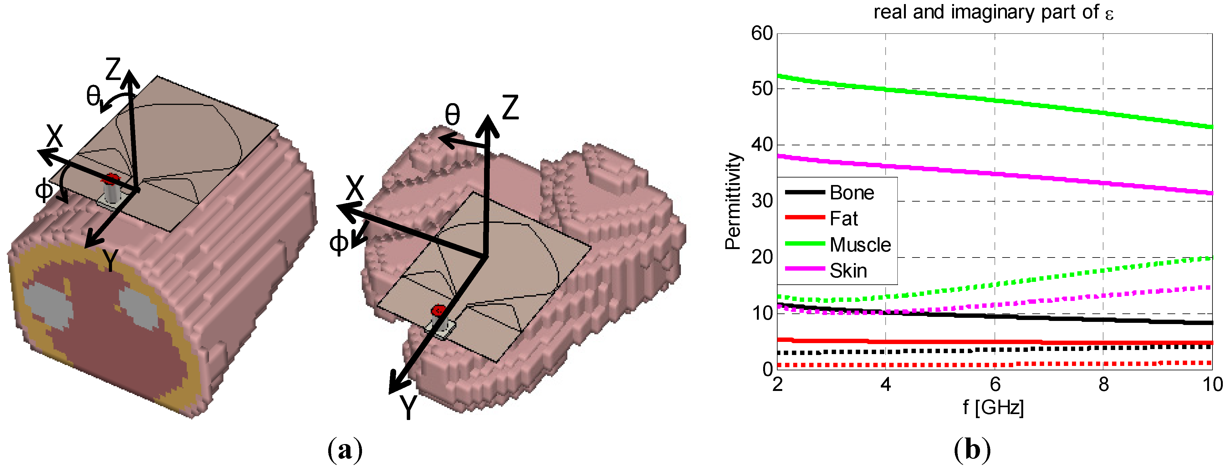
In this section the antenna on-body performances are investigated for two different body locations: the footwear toe-cap and the wrist. The body model consists of voxel files representing the wrist and the foot. In the wrist model case the distance between the antenna and the body is equal to 5 mm. For the footwear case the antenna is located next to the skin voxels. The voxel model of the foot is non‑planar, so the distance between the antenna and the foot varies from 1 mm to 8.5 mm. The foot and wrist models include different body tissues, such as skin, fat, muscle and bone. The electrical properties of these materials are frequency dependent [
19].
The antenna located on the simulated voxel model and the electrical properties of the tissues are shown in
Figure 2.
Figure 2.
(a) On-body model; (b) Electrical properties of the human body materials (continuous line ε1, dotted line ε2).
Figure 2.
(a) On-body model; (b) Electrical properties of the human body materials (continuous line ε1, dotted line ε2).
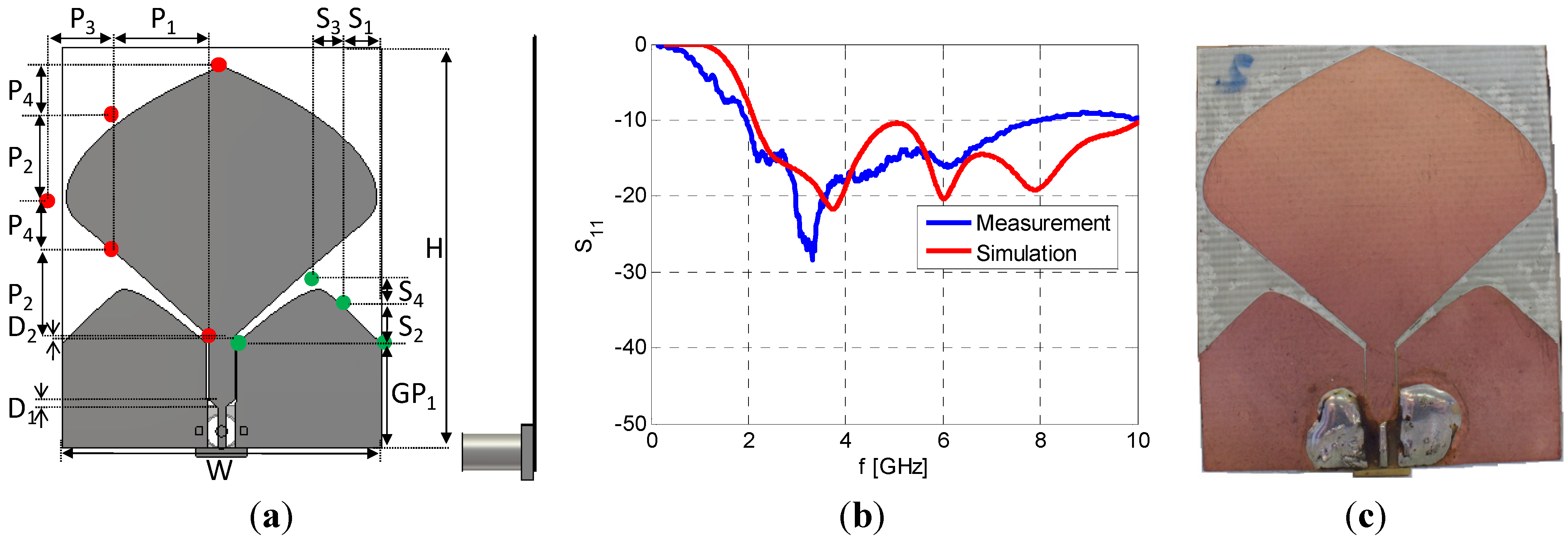
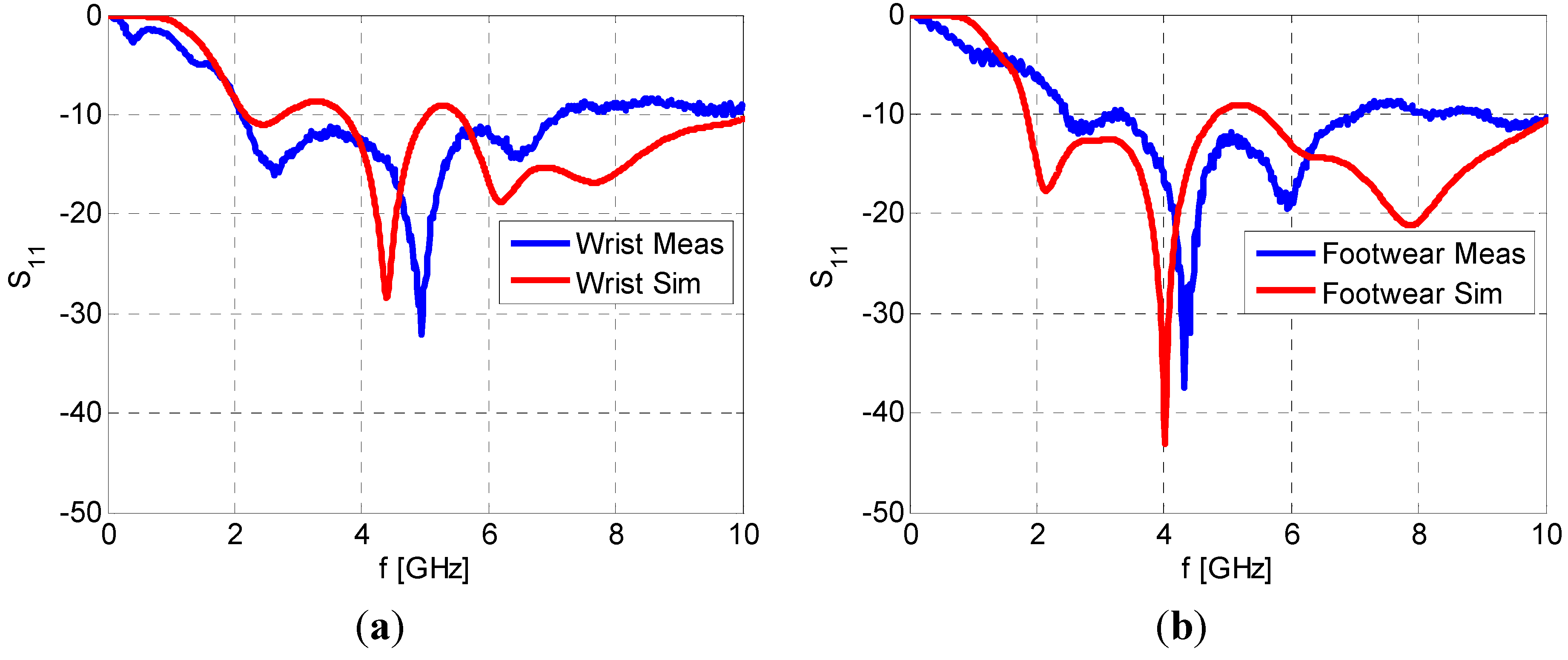
The voxel file resembles the shape of the human body parts and it reproduces the internal geometry. The voxel foot model is mostly composed of bones, characterized by small values of permittivity and losses. The voxel wrist model is mostly composed of high water-content material such as muscle, although there is a thin layer of skin and a thicker layer of fat closer to the antenna. A comparison between simulation and measurement of the antenna located on the footwear and on the wrist are shown in
Figure 3. The shoe materials are not considered in the simulation model. The thin toe cap layer is negligible compared to the close proximity to the high dielectric constant and lossy body tissues.
The measured and simulated S11 of the wrist and toe-cap mounted antennas is less than −8.5 dB across the band of interest.
Figure 3.
Comparison of measured and simulated S11 for wrist (a) and footwear (b).
Figure 3.
Comparison of measured and simulated S11 for wrist (a) and footwear (b).
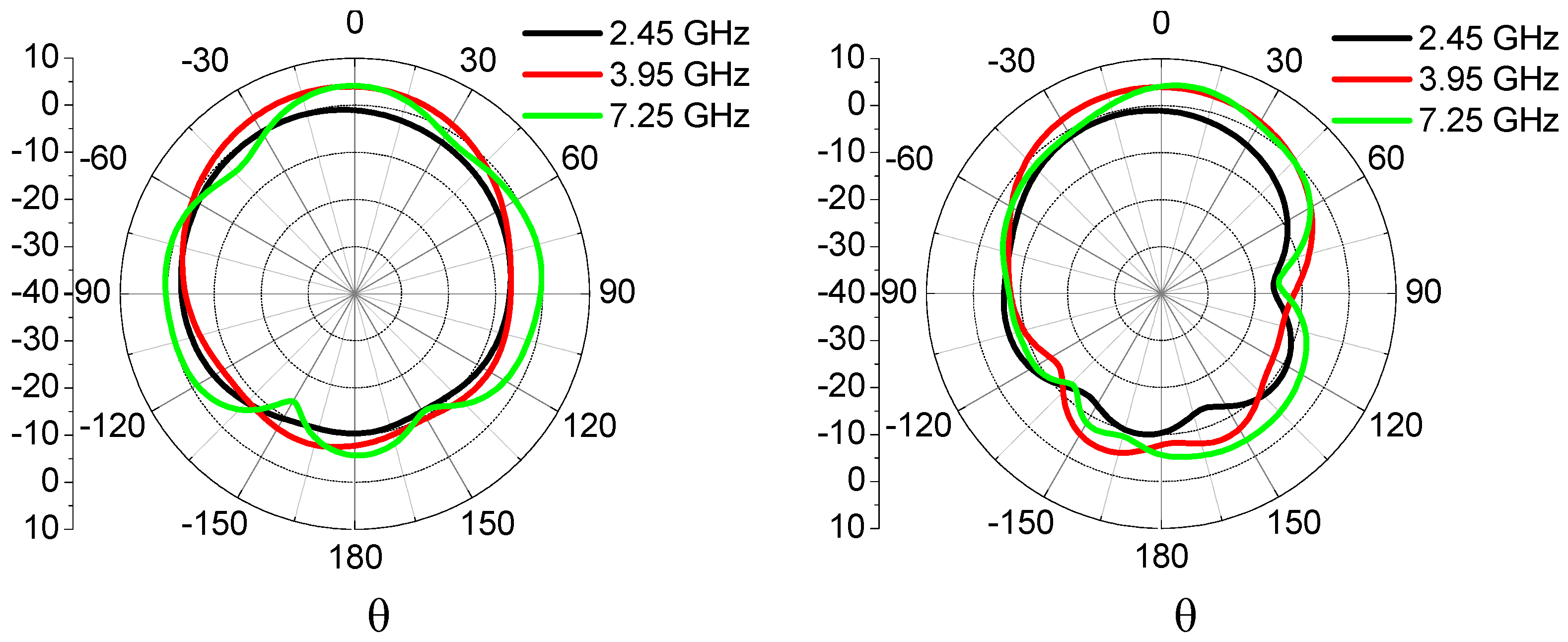
Small disagreements between simulation and measurement are due to differences between the voxel model shape and the actual human case. The antenna was perfectly centered on the wrist with human body tissue equally distributed below the antenna. The loading of the toes in the footwear case is not symmetrical due to the presence of air-spaces and the non-constant antenna-foot separation. The simulated radiation patterns are shown in
Figure 4 and
Figure 5. The realized gain as a function of frequency is summarized in
Table 2.
Figure 4.
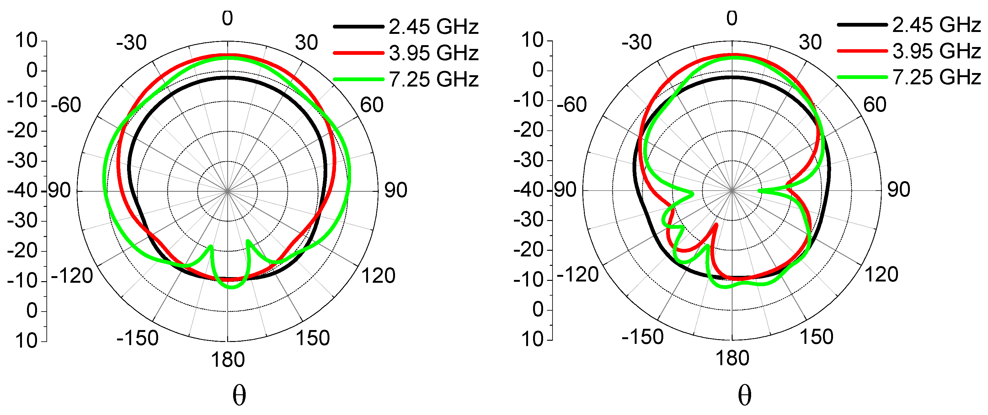
Realized gain patterns for monopole antenna on footwear for φ = 0° and φ = 90°.
Figure 4.
Realized gain patterns for monopole antenna on footwear for φ = 0° and φ = 90°.
Figure 5.
Realized gain patterns for monopole antenna on wrist for φ = 0° and φ = 90°.
Figure 5.
Realized gain patterns for monopole antenna on wrist for φ = 0° and φ = 90°.
Table 2.
Directivity parameters for the on-body antennas.
Table 2.
Directivity parameters for the on-body antennas.
| Frequency [GHz] | Maximum realized gain magnitude [dBi] | 3-dB beamwidth for φ = 0° [deg] | 3-dB beamwidth for φ = 90° [deg] | Radiation efficiency |
|---|
| | Wrist | Footwear | Wrist | Footwear | Wrist | Footwear | Wrist | Footwear |
|---|
| 2.45 | −2.09 | −0.16 | 131.3 | 131.9 | 86.6 | 84.3 | 21% | 30% |
| 3.95 | 5.37 | 4.07 | 86.6 | 83.4 | 61.4 | 80.5 | 54% | 55% |
| 7.25 | 4.41 | 4.46 | 57.1 | 42.7 | 44.3 | 46.1 | 65% | 64% |
The antenna radiation efficiency increases with frequency because the electrical distance between the antenna and the body increases. The difference in the shapes of the radiation pattern for the footwear and the wrist locations is due to dissimilar body geometries and to the different positions of the antenna respect to the body. The antenna is characterized by the maximum realized gain for the 3.95 GHz frequency for the wrist case. Considering a walking subject, the 3 dB beamwidth for φ = 90° for the toe-cap mounted antenna is wide enough to cover the arm swing of the walking subject.
4. Measurements
The S
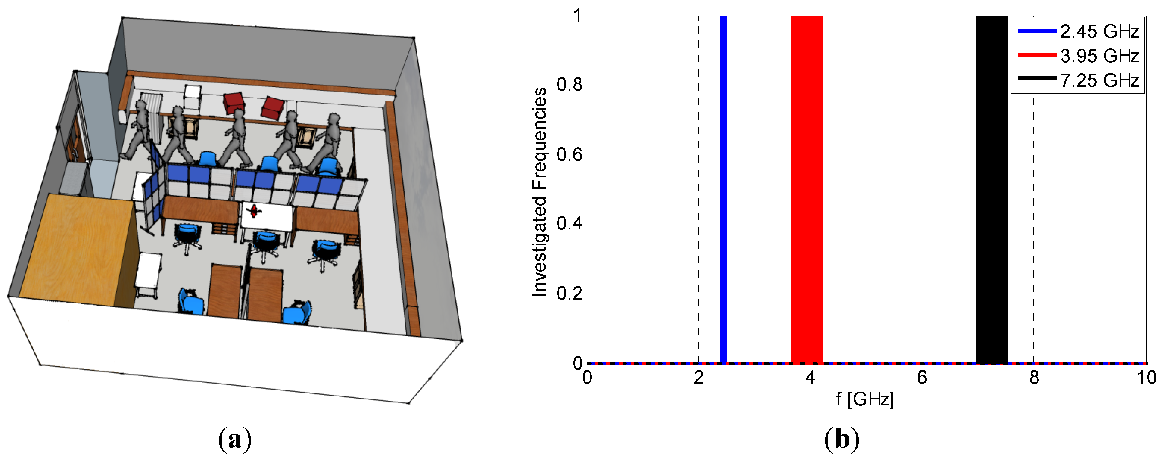
21 was measured using a Rohde & Schwarz ZVA 25 for a subject standing and walking. The measurements are made in a room 8.1 × 7.9 m
2 with furniture and reinforced concrete walls and floors. The person is walking along one side of the room as shown in
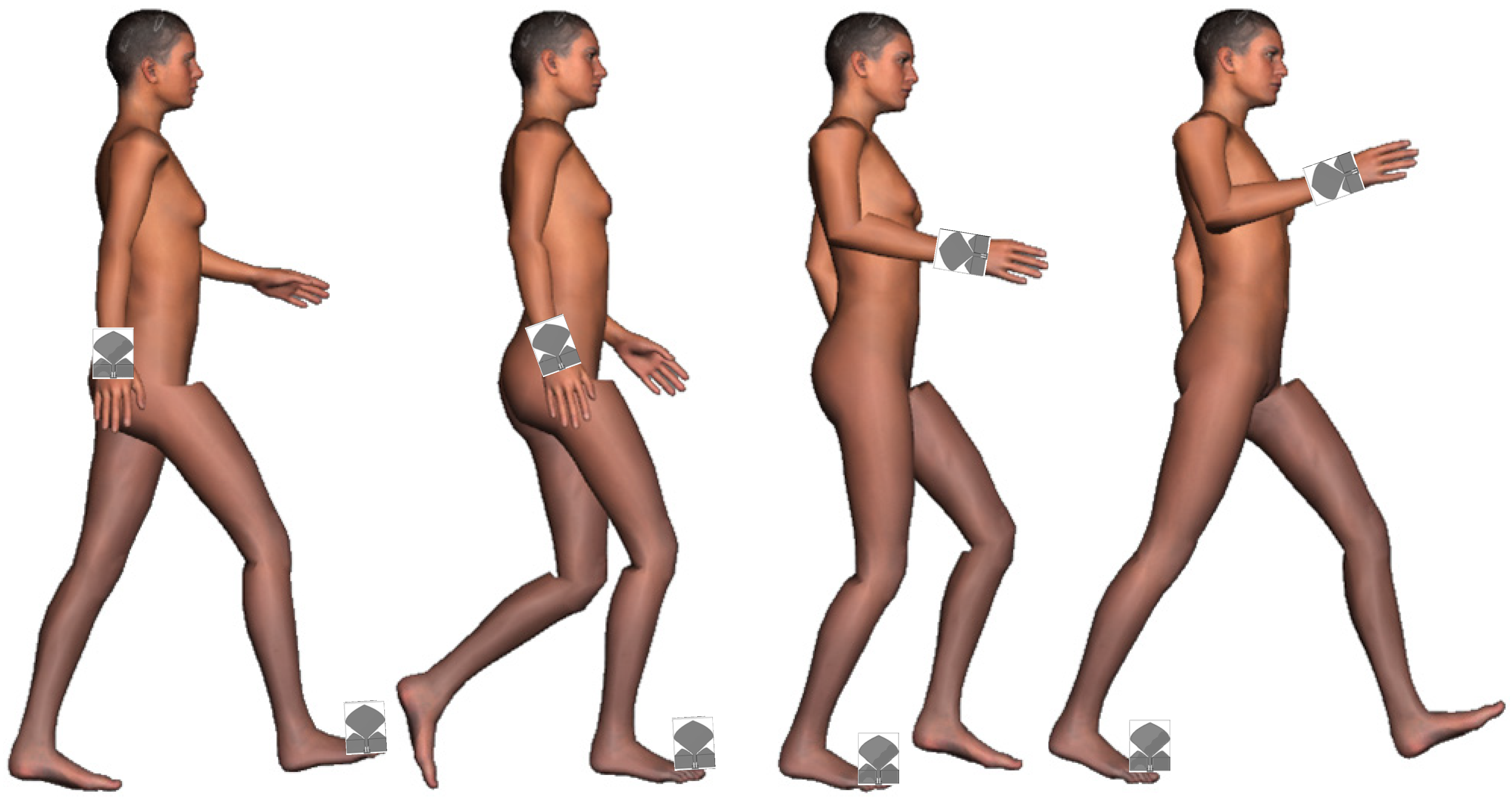
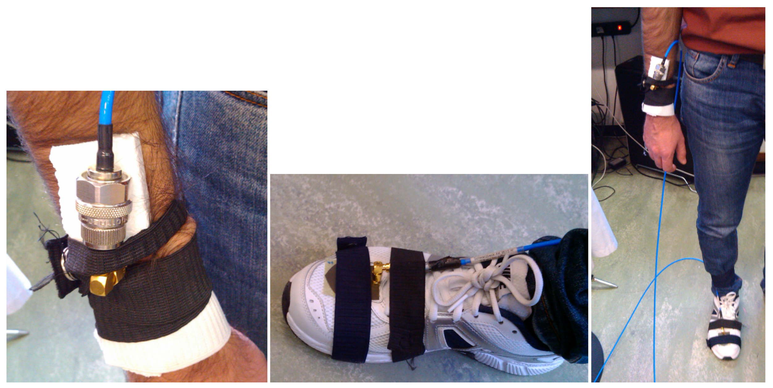
Figure 6a. The first antenna is located on the right-side shoe toe-cap and the second antenna is located above the right wrist, as shown in
Figure 7. Three different frequency bands are analyzed as shown in
Figure 6b:
50 MHz centered at 2.45 GHz
500 MHz centered at 3.95 GHz
500 MHz centered at 7.25 GHz
Figure 6.
(a) Layout of the room; (b) investigated frequencies with bandwidth.
Figure 6.
(a) Layout of the room; (b) investigated frequencies with bandwidth.
The three frequencies represent the centre frequencies for the narrowband and UWB physical layer for wireless BAN networks in IEEE 802.15.6.
Figure 7.
Walking subject with antennas on wrist and toe-cap footwear.
Figure 7.
Walking subject with antennas on wrist and toe-cap footwear.
To avoid obstruction of the cables by the subject walking, the VNA was placed at the side of the room and the cables located behind the subject. In this way the cables trail the walking subject, without impacting on the gait. Photos of the measurement setup are shown in
Figure 8.
Figure 8.
Photos of the on-body antennas.
Figure 8.
Photos of the on-body antennas.
In total there are five measurements with 330 frequency sweep samples for a subject walking and standing. The first 10 s are related to a stationary subject at one side of the room. Then the subject walks to the other side of the room. Finally the subject stands still at the other side of the room. There is a measurement every ~100 ms. The total time for each measurement is ~33 s. The measurements were made on a subject of mass 70 kg and 1.75 m tall. Path loss results are displayed in terms of Cumulative Distribution Function (CDF) and compared with the Rician distribution using the Maximum Likelihood Estimation (MLE) criteria.
4.1. Narrowband Channel—2.45 GHz
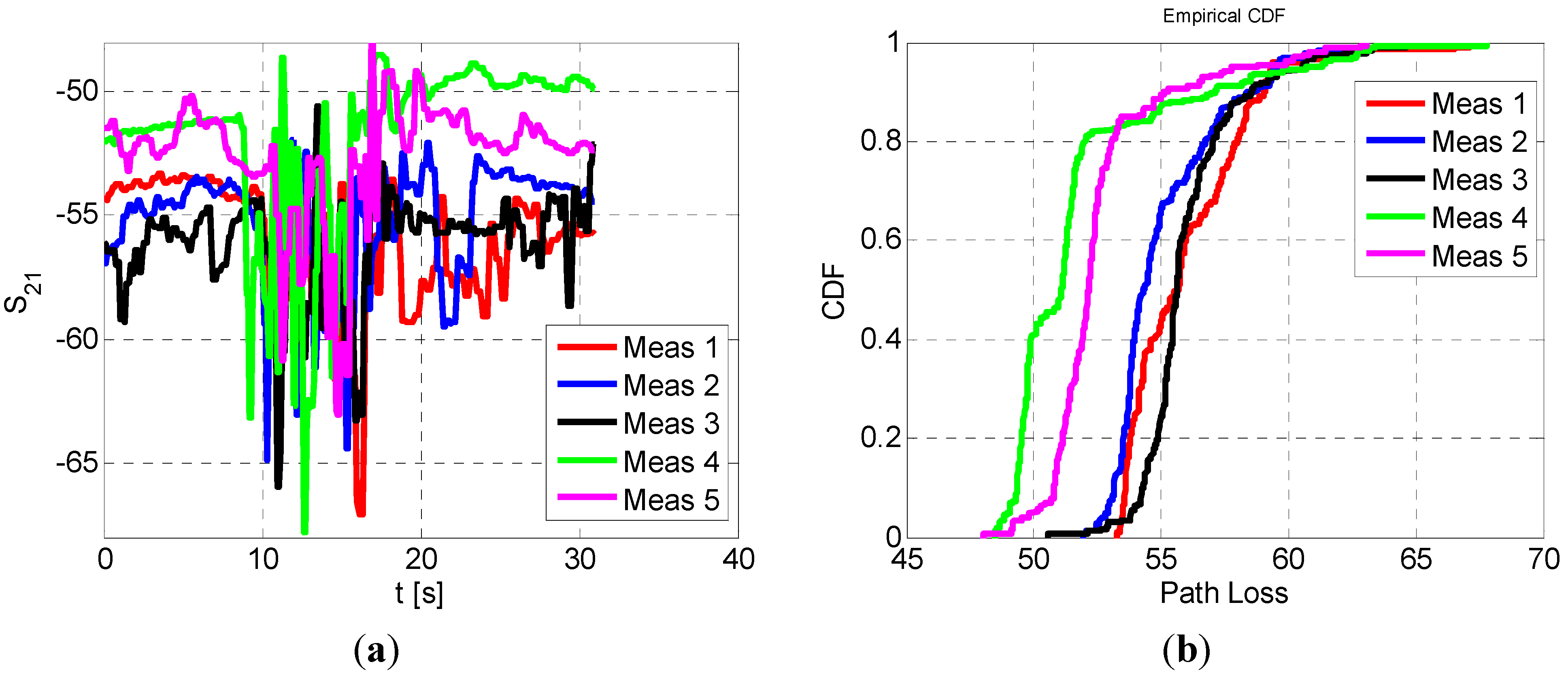
In this paragraph the results for the 2.45 GHz narrowband channel is investigated. The link channel measured in the five campaigns of measurements as a function of time is shown in
Figure 9a. For the first 10 s, the variation in the channel is small (between −59 dB and −50 dB). When the subject starts walking the S
21 oscillation increases, but remaining between −67.8 dB and −48 dB. Finally the subject is standing in front of a wall, and the S
21 is almost constant for each set of measurements. The CDF of the five measurements is shown in
Figure 9b. The minimum and the maximum values of the five measurements are summarized in
Table 3. Considering all the measurements, the maximum range is equal to 19 dB. The CDF is compared with the MLE for the corresponding Rician Distribution, assuming that there is a main ray between the foot and the wrist.
Figure 9.
(a) measured S21 for a subject walking; (b) CDF of the path loss for the five cases.
Figure 9.
(a) measured S21 for a subject walking; (b) CDF of the path loss for the five cases.
Table 3.
K-factor estimation for the different measurements for the 2.45 GHz channel.
Table 3.
K-factor estimation for the different measurements for the 2.45 GHz channel.
| | Minimum path loss [dB] | Maximum path loss [dB] | K-factor [dB] |
|---|
| Meas 1 | 53 | 67 | 9.16 |
| Meas 2 | 52 | 65 | 9.97 |
| Meas 3 | 50 | 66 | 10.5 |
| Meas 4 | 48 | 68 | 7.5 |
| Meas 5 | 48 | 63 | 9.7 |
The K-factor of the Rician distribution is summarized in
Table 3. All the measurements are characterized by a K-factor always greater than 7.5 dB, evidencing the presence of a main component of the received signal greater than the scattered components. The range of K-factors spans from 7.5 dB to 10.5 dB. The path loss is always smaller than 67 dB.
4.2. Lower UWB Channel 3.95 GHz
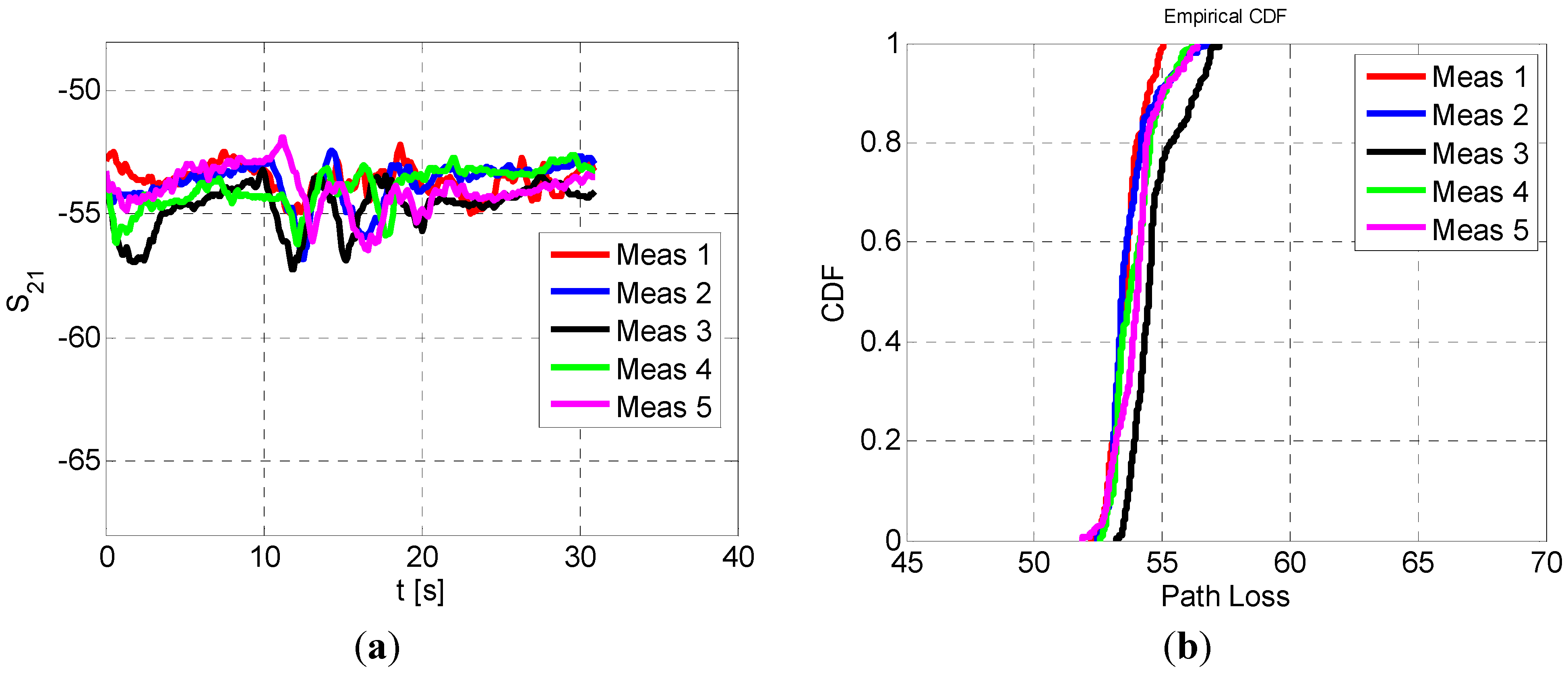
In this section the results of the lower UWB channel are shown. The investigated centre frequency is 3.95 GHz with 500 MHz bandwidth. The S
21 measurements of a walking subject as a function of the time, is shown in
Figure 10a. The S
21 is almost constant for the stationary subject at the starting point and in front of the wall. When the subject is walking the S
21 oscillates with a greater range of values, with peaks of maximum S
21 equal to −51.89 dB and minima of −57.23 dB. The CDF of the five measurements is shown in
Figure 10b.
Figure 10.
(a) Measured S21 for a walking subject; (b) CDF of the path loss for the five cases.
Figure 10.
(a) Measured S21 for a walking subject; (b) CDF of the path loss for the five cases.
The CDF distributions for the measurements are very similar.
Table 4 summarizes the minimum and maximum values and the K-factor for the corresponding Rician distribution. The K-factor for the 3.95 GHz frequency range is always greater than 16.2, corresponding to a more directive link between the footwear and the wrist compared to the 2.45 GHz case. This is also due to a greater antenna realized gain compared to the 2.45 GHz case. The increased bandwidth decreases the fading, reducing the maximum path loss variation to 4 dB. The greater K-factor compared to the narrowband channel can also be explained by the smaller antenna beamwidth, reducing reflected signals from the surrounding environment.
Table 4.
K-factor estimation for the different measurements for the 3.95 GHz channel.
Table 4.
K-factor estimation for the different measurements for the 3.95 GHz channel.
| | Minimum path loss [dB] | Maximum path loss [dB] | K-factor [dB] |
|---|
| Meas 1 | 52 | 52 | 20.5 |
| Meas 2 | 53 | 57 | 18.0 |
| Meas 3 | 53 | 57 | 16.2 |
| Meas 4 | 55 | 56 | 17.2 |
| Meas 5 | 52 | 57 | 17.3 |
4.3. Upper UWB Channel 7.25 GHz
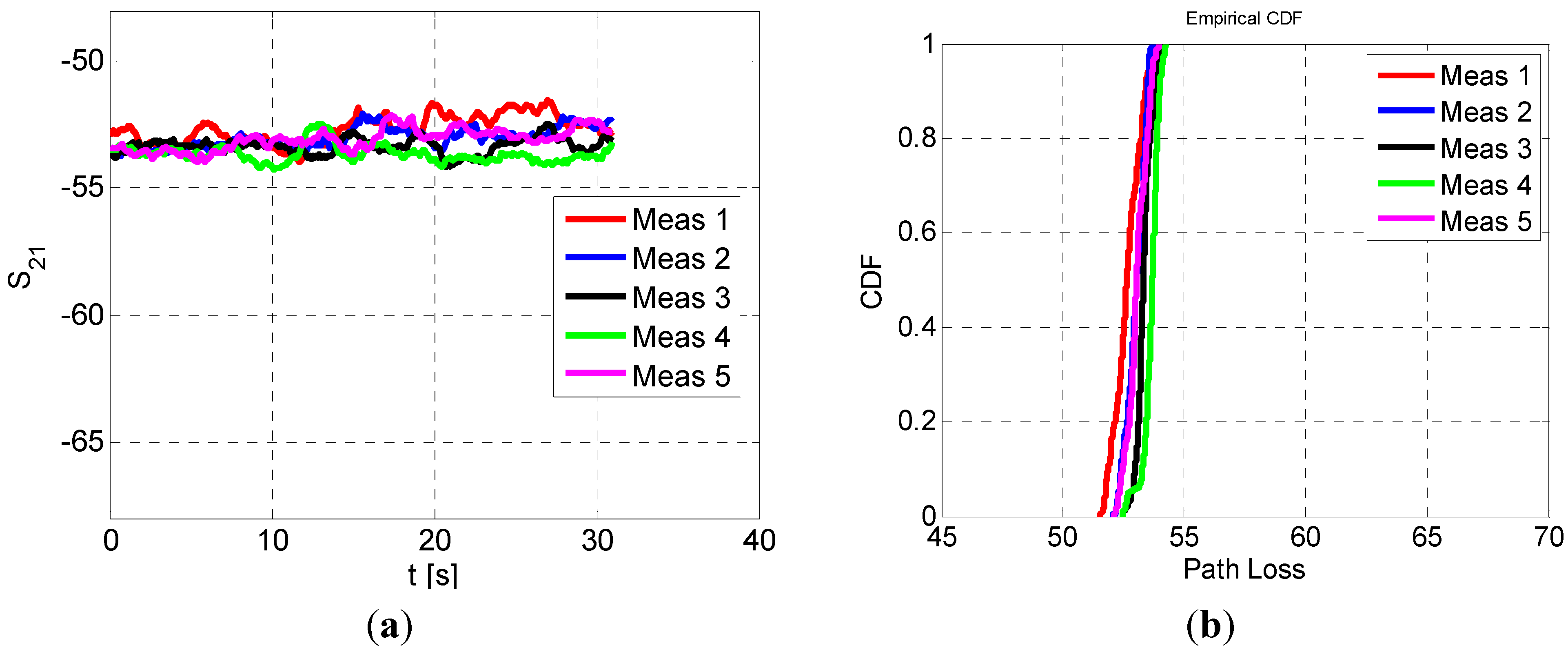
The performance for the upper UWB band is also investigated. The centre frequency is 7.25 GHz with a 500 MHz bandwidth. In
Figure 11a the measured S
21 for the walking subject as a function of time are shown. As observed for previous cases, the S
21 is almost constant for the first 10 s, with a S
21 value equal to ~−53.5 dB. When the subject is walking, the S
21 range remains between −54.22 dB and −51.56 dB. Finally when the subject is stationary at the end of the room the S
21 is almost constant and equal to −53.75 dB. The CDFs of the five measurements are shown in
Figure 11b. In this case the measurements are much closer to each other. The measured path loss values and K-factors are summarized in
Table 5. The K-factor is greater than the previous case and always greater than 20.9 dB. The difference between the maximum and the minimum K-factor is equal to 5.1 dB.
Figure 11.
(a) Measured S21 for a walking subject; (b) CDF of the path loss for the five cases.
Figure 11.
(a) Measured S21 for a walking subject; (b) CDF of the path loss for the five cases.
Table 5.
K-factor estimation for the different measurements for the 7.25 GHz channel.
Table 5.
K-factor estimation for the different measurements for the 7.25 GHz channel.
| | Minimum path loss [dB] | Maximum path loss [dB] | K-factor [dB] |
|---|
| Meas 1 | 52 | 54 | 20.9 |
| Meas 2 | 52 | 54 | 23.7 |
| Meas 3 | 52 | 54 | 26.0 |
| Meas 4 | 52 | 54 | 24.9 |
| Meas 5 | 52 | 54 | 23.3 |
As expected, the K-factor is greater than the previous cases. Although the maximum realized gain is less than the 3.95 GHz case, the beamwidth of the antenna is smaller, resulting in a decreased signal scattering in the surrounding environment. The minimum path loss values are similar to the 3.95 GHz because of the greater realized gain for the footwear antenna.
5. Conclusions
The S21 link between the wrist and footwear toe-cap is reported for a subject standing and walking. A monopole antenna is optimized for different on-body locations at 2.45 GHz, 3.95 GHz and 7.25 GHz. The results are summarized in terms of Cumulative Distribution Functions and the Maximum Likelihood Estimation criteria are used for K-factor parameter fit to a Rician distribution.
In the subject standing pose, the S21 remains persistent for each of the three frequencies. When the subject is walking, the S21 varies rapidly with lower S21 values for lower frequencies. This is attributed to channel fading and shadowing by the hand during the arm swing motion associated with walking. At the lower frequency, the fading is more noticeable because the selected channel is narrowband.
The UWB channels are an easier fit to a Rician distribution, with small changes of the K-factor. In the 2.45 GHz case, the Rician K-factor is ~10 dB lower than that for the UWB channels. This is due to the larger beamwidth at 2.45 GHz which increases the signal scattering from surrounding environment. The minimum path loss for each of the UWB channels is the same due to higher antenna efficiency. The 7.25 GHz channel is characterized by the largest K-factor due to its smaller beamwidth. The communication link complies with the standard for each of the measured cases for a subject standing and walking.
Further work will consider the receiving node in different body locations; hence it will establish the optimum frequency band for different body locations. The antenna will be tested in an outdoor environment and with different transceivers to mitigate cable effects.

