Article

Radiation Pattern Measurement of a Low-Profile Wearable Antenna Using an Optical Fibre and a Solid Anthropomorphic Phantom

1
Time, Quantum and Electromagnetics Division, National Physical Laboratory, Hampton Road, Teddington, Middlesex TW11 0LW, UK
2
Department of Physics and Astronomy, The University of Sheffield, Western Bank, Sheffield S10 2TN, UK
*
Author to whom correspondence should be addressed.
Electronics 2014, 3(3), 462-473; https://doi.org/10.3390/electronics3030462
Submission received: 28 March 2014 / Revised: 23 June 2014 / Accepted: 27 June 2014 / Published: 5 August 2014
(This article belongs to the Special Issue Wearable Electronics)

Abstract

:
This paper presents a study into radiation pattern measurements of an electrically small dielectric resonator antenna (DRA) operating between 2.4 and 2.5 GHz in the industrial, scientific and medical (ISM) radio band for body-centric wireless communication applications. To eliminate the distortion of the radiation pattern associated with the unwanted radiation from a metallic coaxial cable feeding the antenna we have replaced it with a fibre optic feed and an electro-optical (EO) transducer. The optical signal is then converted back to RF using an Opto-Electric Field Sensor (OEFS) system. To ensure traceable measurements of the radiation pattern performance of the wearable antenna a generic head and torso solid anthropomorphic phantom model has been employed. Furthermore, to illustrate the benefits of the method, numerical simulations of the co-polar and cross-polar H-plane radiation patterns at 2.4, 2.45, and 2.5 GHz are compared with the measured results obtained using: (i) an optical fibre; and (ii) a metallic coaxial cable.

1. Introduction

The rapid growth of the wireless communications market has resulted in new applications constantly being developed. Body-worn (wearable) antennas constitute an emerging and rapidly growing technology. The progress in the textile and wearable electronics industry [1,2,3,4] made it easier for such antennas to be implemented into cloths and to invade the market. Their development is of increasing interest for health monitoring, defense and the communications industries [4,5,6,7,8,9,10,11,12]. Such antennas enable body-centric wireless communications and it is envisaged that they will play a key role in the development of future generation mobile communications [13,14,15,16,17,18].
Most applications require wearable antennas to be unobtrusive, low-profile, low-power and electrically small. Due to power absorption by lossy human body tissues, a distorted radiation pattern and lower radiation efficiency is envisaged when they are worn on and at close proximity to the body [19]. To improve the antenna radiation efficiency and reduce the power absorption by the body, methods such as adding an additional spacer layer [20], electromagnetic band gap substrates [21], reflection plane substrates [22] or textile fabric substrates [23] between the body and the wearable antennas have been proposed. Furthermore, when designing the antenna the body proximity effects must be considered to prevent significant antenna detuning and the consequent mismatch [19,24]. One method is to optimize the impedance matching when in proximity to the tissue. However, such method may suffer the resilience to proximity detuning when the antenna-to-body distance varies. An improved design method to develop the antenna to have good impedance matching in the presence of tissue and also to have resilience to distance-dependent antenna detuning has been proposed in [24].
When testing a prototype wearable antenna, it is normal to connect it to a metallic coaxial feed cable, even though such a cable may not be present in the final application of the antenna. This makes it difficult to assess the radiation performance of such antennas especially ones without a balun or adequate balancing match, as they are prone to unwanted common mode currents on the metallic coaxial cable used to feed the antenna during the measurement [25]. These problems have been shown to be far from trivial and they interfere with the radiation of the antenna, which can cause differences between the measured pattern and the expected pattern [25,26,27]. Furthermore, the resultant creeping or surface wave propagation around the body excited by both the wearable antenna and coaxial cable would affect the on-body communication channel performance. Several battery-free electro-optic (EO) transducer technologies [25,28] have been developed that allows the metallic coaxial cable feeding the antenna to be replaced by an optical fibre.
Without insight into the cause of the deviations in the measured radiation pattern, the designer can spend fruitless efforts redesigning the antenna, which can limit the uptake of these technologies. Suitable measurement facilities and phantoms are required to ensure accurate and repeatable traceable measurements of the radiation performance of these antennas. In this study a head and torso solid anthropomorphic phantom that matches the characteristics of human biological tissues is employed [29].
This paper presents a study into measurement of the radiation pattern of a body-wearable electrically small dielectric resonator antenna (DRA) using a non-invasive Opto-Electric Field Sensor (OEFS) optical fibre link system. The antenna operates between 2.4 and 2.5 GHz in the industrial, scientific and medical (ISM) radio band and is used for body-centric wireless communication applications. The aim is to establish traceable measurement methods to assess body worn antenna radiation performance using an optical fibre link, an anechoic chamber and a solid anthropomorphic phantom, whose electromagnetic properties sufficiently match those of human tissue and organs over the frequency range of interest. The paper is organized as follows: Section 2 presents the details of measurement facilities and experimental and numerical setups for the radiation pattern measurements of the DRA antenna attached to the solid anthropomorphic phantom. Section 3 shows a comparison between the radiation pattern results obtained from the simulation, and the measurement using the optical fibre and the metallic coaxial cable. Finally, conclusions are drawn in Section 4.

2. Experimental and Numerical Setups

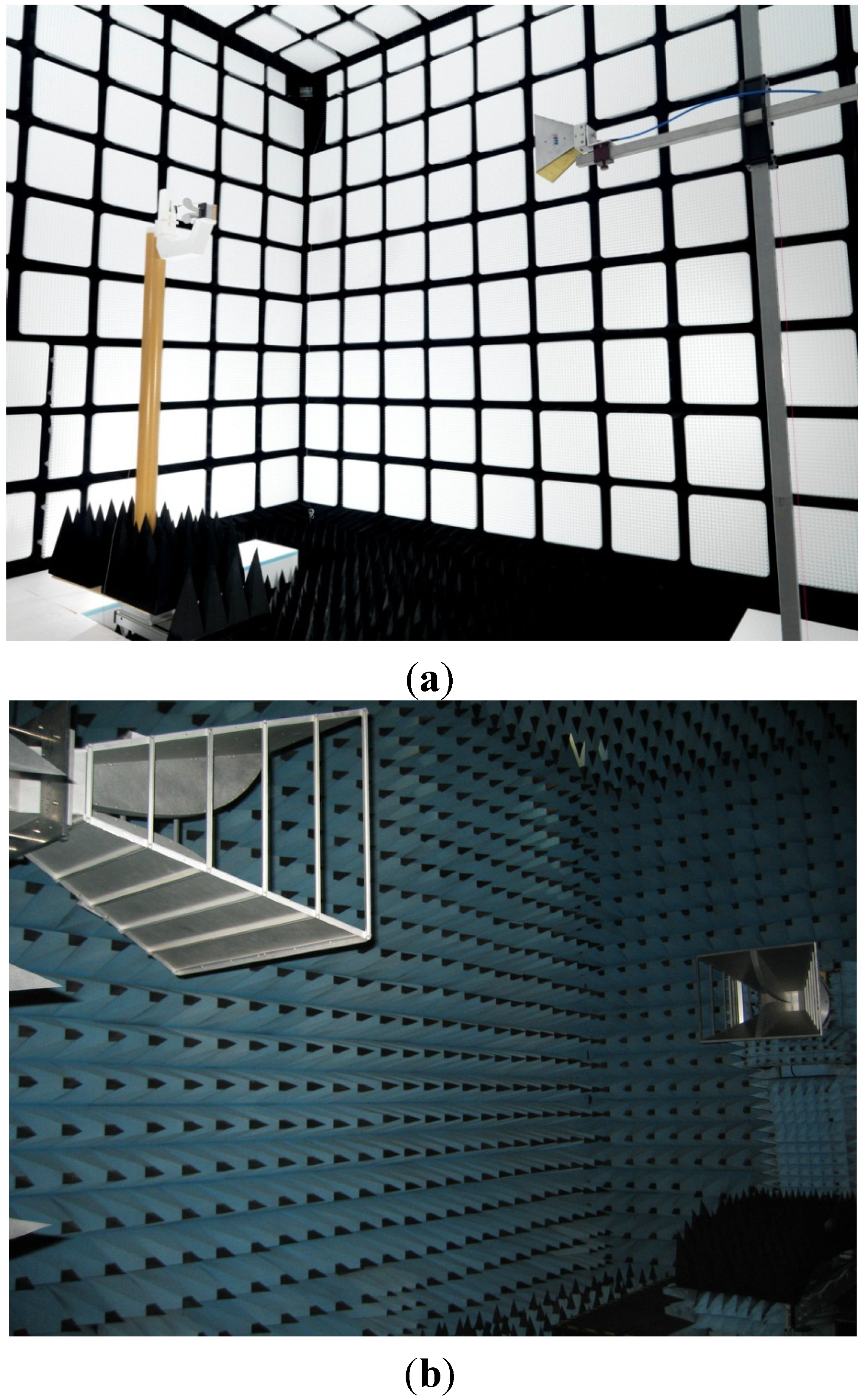
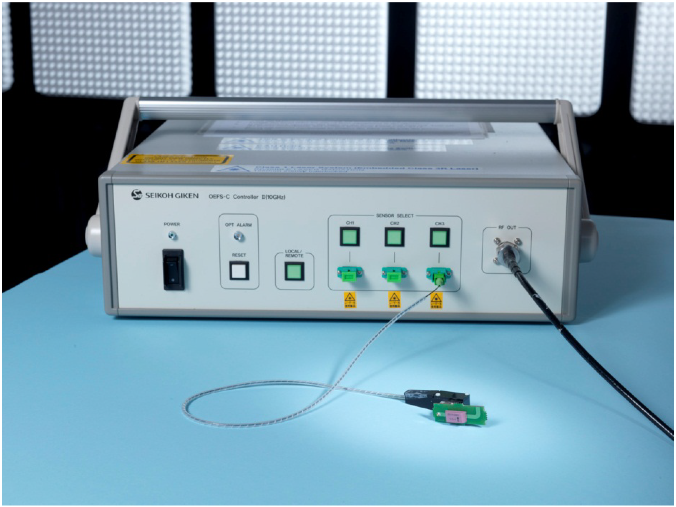
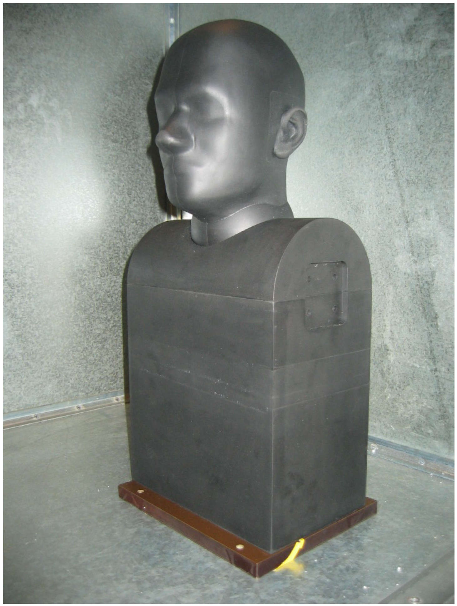
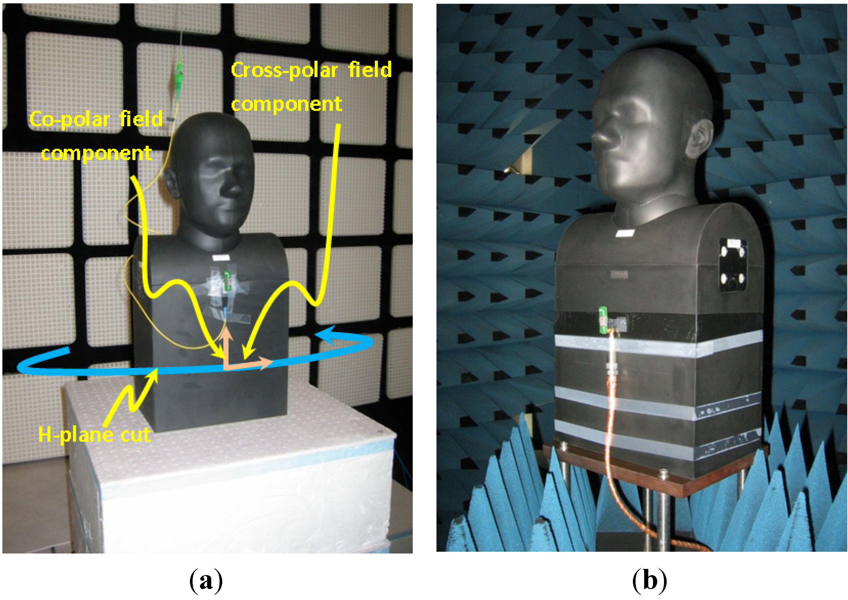
2.1. Experimental Setup

All the radiation pattern measurements were performed in fully anechoic chambers at the UK National Physical Laboratory (NPL). The two anechoic chambers used were: (i) the Small-Antenna Radiated Testing (SMART) chamber (see Figure 1a); and (ii) the Microwave Antenna Extrapolation Testing (MAET) range (see Figure 1b).
Figure 1. (a) The National Physical Laboratory (NPL) Small-Antenna Radiated Testing (SMART) range; (b) The NPL Microwave Antenna Extrapolation Testing (MAET) range.
Electronics 03 00462 g001
The SMART chamber has dimensions of 7.15 m × 6.25 m × 6.25 m and a frequency range of operation between 400 MHz and 26.5 GHz, whereas the MAET range has dimensions of 15 m × 7.5 m × 7.5 m and a frequency range of operation between 400 MHz and 110 GHz. They are both fully anechoic with the RF absorbing material on all the walls, the floor and the ceiling.
The electrically small DRA (see Figure 2) considered is developed by Antenova Ltd. (Hatfield, Herts, UK) for IEEE802.11b/g applications and has a dipole-like radiation pattern [25] when it is measured in free-space. The opto-electric fibre system consists of a battery free EO transducer connected to an OEFS controller system via an optical fibre link and the system operate from 300 kHz to 10 GHz. The OEFS controller system comprises a semi-conductor laser, an optical circulator, a photo-detector and a 30 dB RF amplifier. It supplies optical power to the EO transducer, uses the electrodes on an X-cut lithium-niobate crystal chip to modulate laser light with an RF signal from the DRA, and converts the returned detected optical signal transmitted via optical fibre to a detector diode into an RF electric signal at the output of the OEFS controller system. The magnitude and phase of the converted RF signal are preserved as if there had been no intervening optical components and the converted RF signal is then amplified and transmitted via a metallic coaxial cable to a vector network analyser (VNA). Figure 2 shows the DRA antenna connected directly to the EO transducer and OEFS controller system.
Figure 2. The dielectric resonator antenna (DRA) antenna connected directly to the opto-electric fibre system.
Electronics 03 00462 g002
Figure 3 shows the generic head and torso solid anthropomorphic phantom model employed in this work, which was developed and manufactured by Schmid & Partner AG (SPEAG) (Zurich, Switzerland) [29]. It has a weight of about 40 kg and is made from carbon-loaded silicon rubber in order to mimick the characteristics of human biological tissues over the frequency range 300 MHz to 6 GHz. It is envisaged that the phantom will provide a repeatable and more realistic solution for assessing the radiation performance of head and torso mounted devices.
Using a flanged open ended waveguide WG8 port, measurements of complex reflection-coefficient were obtained. Using modal analysis software developed in [30], dielectric properties were obtained by iteration. The model used assumes a cavity geometry, which differs from the actual measurement geometry as the phantom is not contained within a cavity; however tests showed that for a large and high loss material, adequate results could be obtained if large cavity dimensions were assigned during the computation. Within the frequency range of interest, the phantom was measured in several orientations to provide an indication of its actual inhomogeneity where the rough values of the real permittivity vary between 24 and 34 whereas the values of the conductivity vary between 0.7 and 0.9 S/m. Outliers were assumed to be caused by significant local inhomogeneity and excluded. The chosen results are shown in Table 1 and these were used in the numerical simulations described in Section 2.2 in which the phantom was modelled as a homogeneous medium.
Figure 3. The generic head and torso solid anthropomorphic phantom.
Electronics 03 00462 g003
Table 1. The measured dielectric properties of the anthropomorphic phantom.
Frequency (GHz)Real Part of Relative PermittivityConductivity (S/m)
2.434.30.922
2.4534.210.921
2.534.040.981
In this study the DRA was oriented parallel to the front plane of the anthropomorphic phantom so that the antenna axis is vertical when the phantom is in a standing position and horizontal when the phantom is in a lying position. Hence the antenna under test (AUT) consists of both the DRA and the anthropomorphic phantom. It is envisaged that the omni-directional radiation pattern of the DRA will be distorted due to the reflexion and creeping waves diffraction phenomena induced by the anthropomorphic phantom. The radiation pattern measurements using a metallic coaxial cable and EO transducer were then performed in the MAET range and the SMART chamber respectively. The transducer used was the Seikoh-Giken (Matsudo City, Chiba, Japan) OEFS-6S-002, which was connected via an optical fibre to an OEFS “OEFS-CII-10 GHz” controller.
Figure 4 shows photographs of the two experimental setups for measuring the AUT using a metallic coaxial cable and a fibre optic. Both chambers contain a roll-over-azimuth positioner system, which enables the three-dimensional radiation pattern of the AUT placed over the centre of rotation of the positioner to be measured. It is noted that the roll-axis positioner in the SMART chamber can only handle AUTs of weight up to 10 kg whereas the roll-axis positioner in the MAET range can handle AUTs of weight up to 250 kg. As the AUT has a weight of about 40 kg, only an azimuth cut of the radiation pattern was acquired within the SMART chamber whereas a full spherical pattern was acquired within the MAET range.
Figure 4. Photographs of the experimental setup for pattern measurements of the DRA with head and torso solid anthropomorphic phantom using: (a) fibre; (b) cable.
Electronics 03 00462 g004
An ETS-Lindgren 3117 double-ridged waveguide horn antenna was used as the transmitting antenna. An Agilent Technologies (Wokingham, Berkshire, UK) PNA-X VNA was used with an output power of 0 dBm. Both co- and cross-polar radiation pattern measurements of the H-plane cut (see Figure 4a) were performed with an angular resolution of 5°.

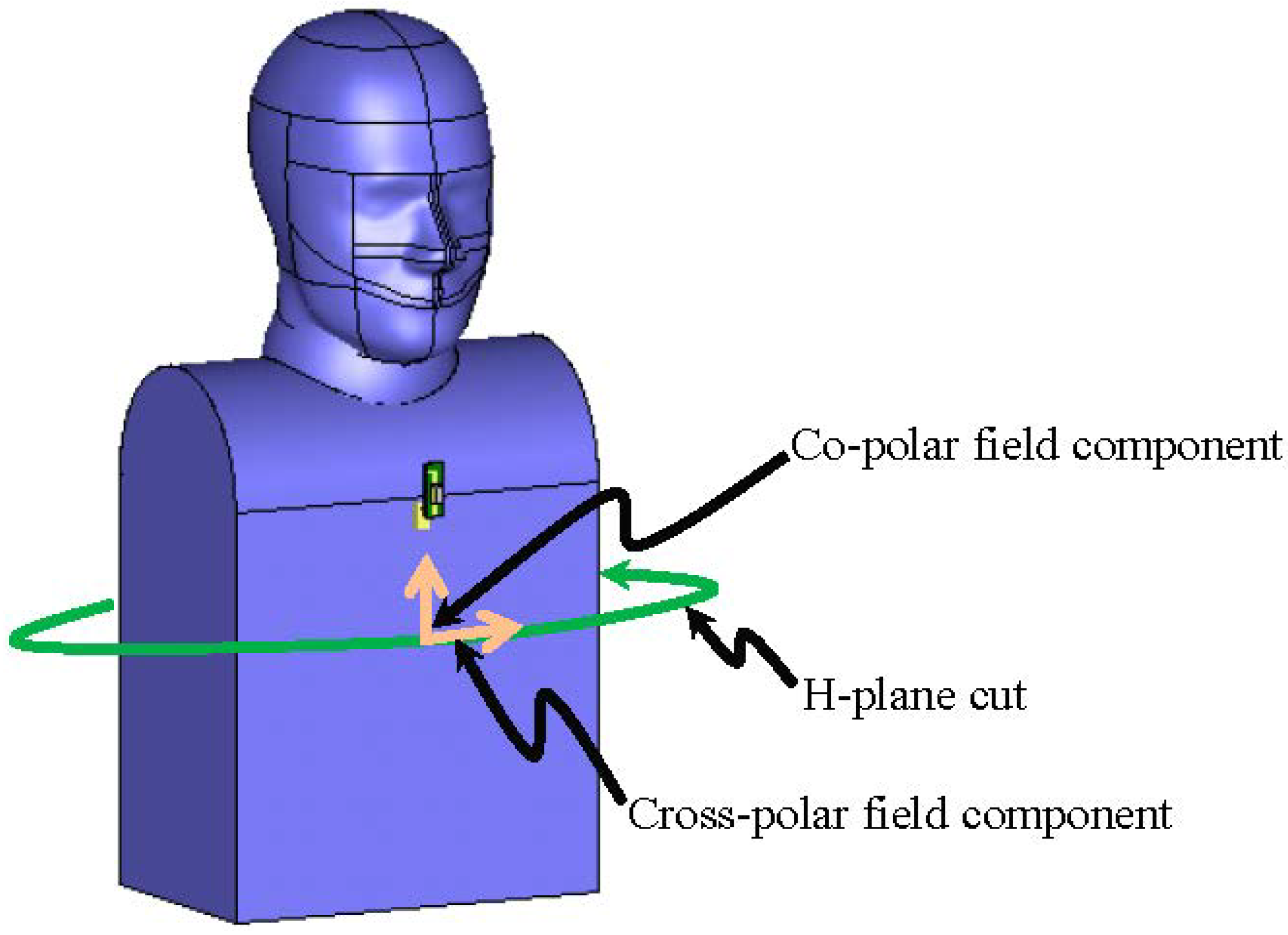
2.2. Numerical Setup

Numerical electromagnetic simulations of the DRA antenna and anthropomorphic phantom were performed using the commercial time domain software package CST Microwave Studio (MWS) [31] that is based on the finite integration technique. Figure 5a shows the numerical setup of the electrically small DRA. Earlier numerical and experimental results relating to the radiation pattern measurements of the DRA were given in [25] in which the effect of common mode currents was examined when different metal/non-metal cased EO transducers, or a metallic quarter-wave choke were used. In the simulation of the DRA, the SubMiniature version A (SMA) adapter and the metallic cased EO transducer were included (see Figure 5b) as their sizes are comparable to the antenna and so they could potentially influence the antenna radiation pattern.
Figure 6 shows the numerical setup of the DRA with head and torso anthropomorphic phantom. The dimensions of the solid anthropomorphic phantom were measured and entered into the simulation software in order to accurately represent the phantom in the numerical model. The geometry of the head of the phantom was imported into the simulation software using a three-dimensional mesh provided by the manufacturer Schmid & Partner Engineering AG (Zurich, Switzerland). The values of the measured frequency-dependent complex permittivity of the phantom (see Table 1) were entered into the simulation software to correctly model the dispersive properties of the phantom.
Figure 5. The electrically small DRA: (a) without; and (b) with SubMiniature version A (SMA) adaptor and the metallic cased EO transducer.
Electronics 03 00462 g005
Figure 6. Numerical model of the DRA with head and torso anthropomorphic phantom.
Electronics 03 00462 g006

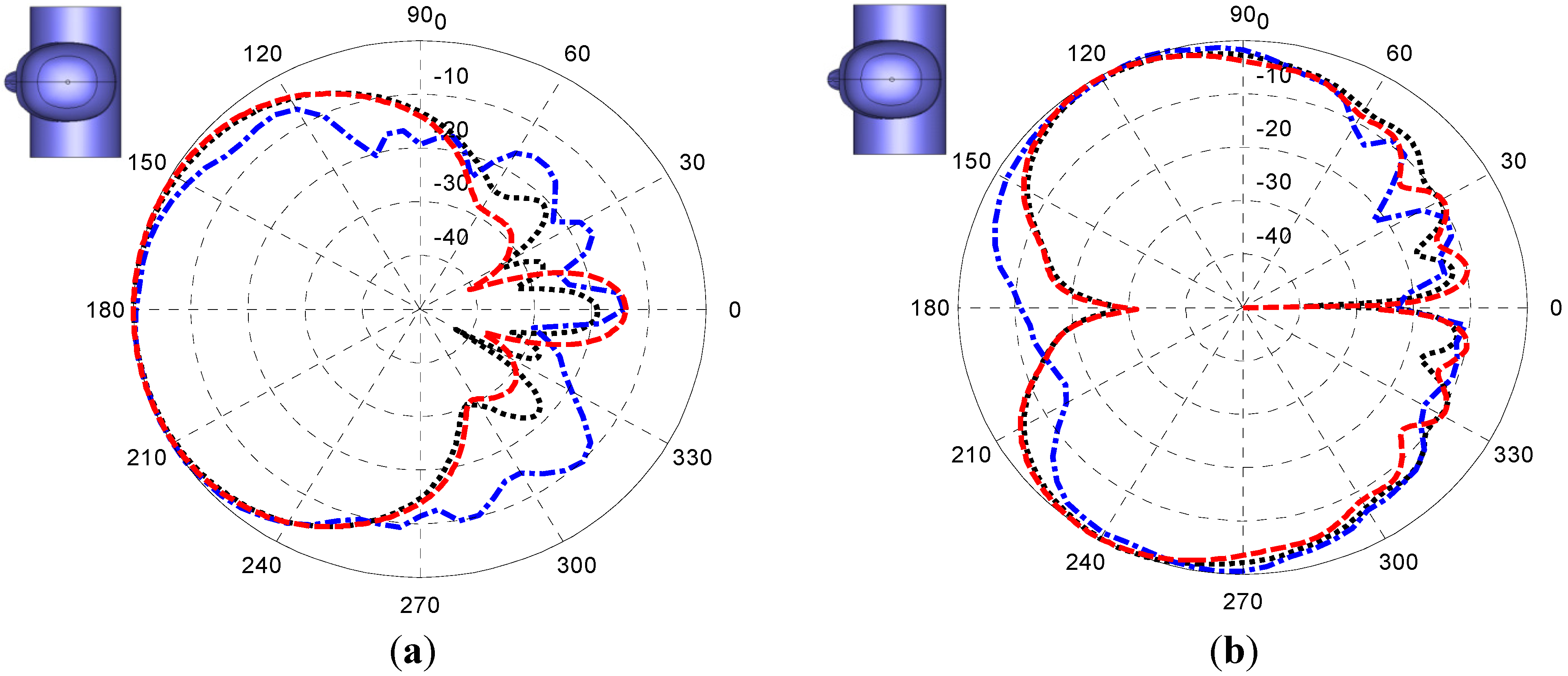
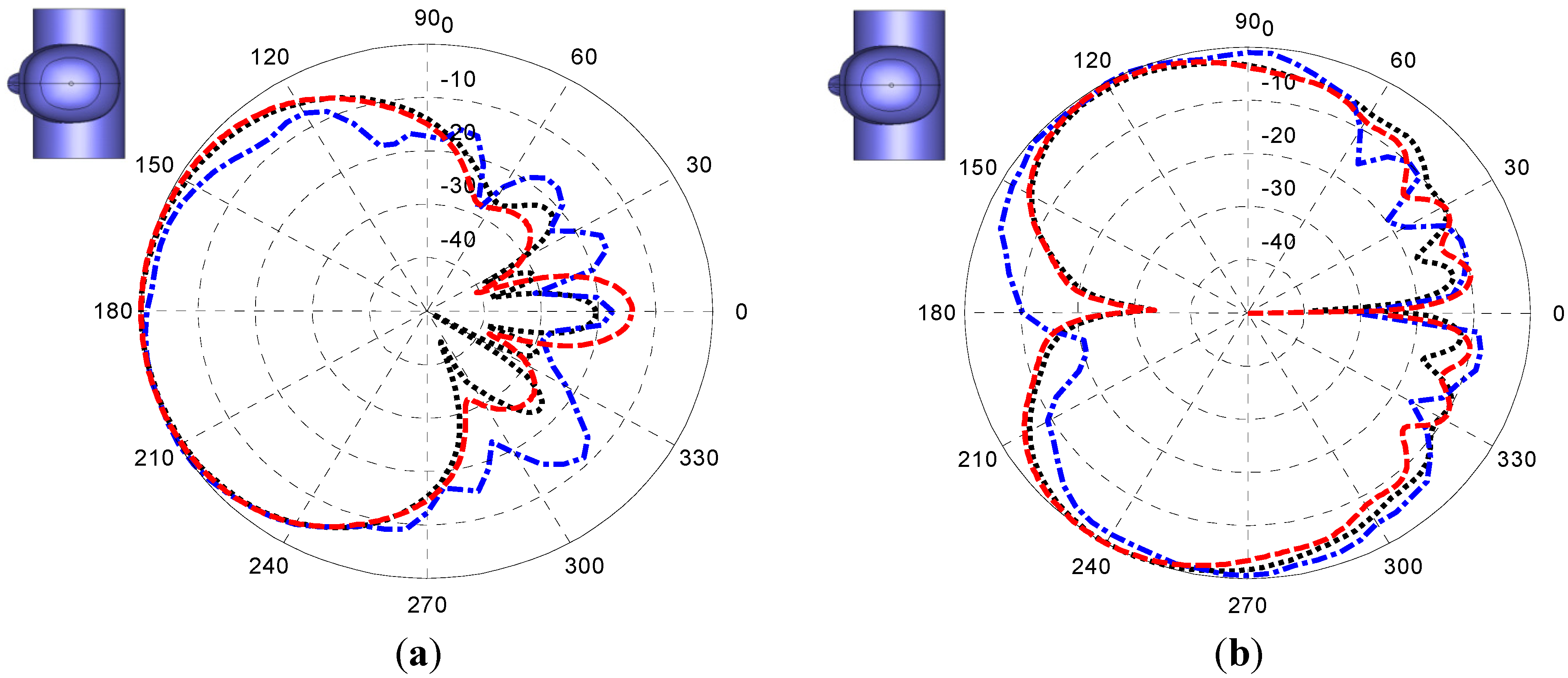
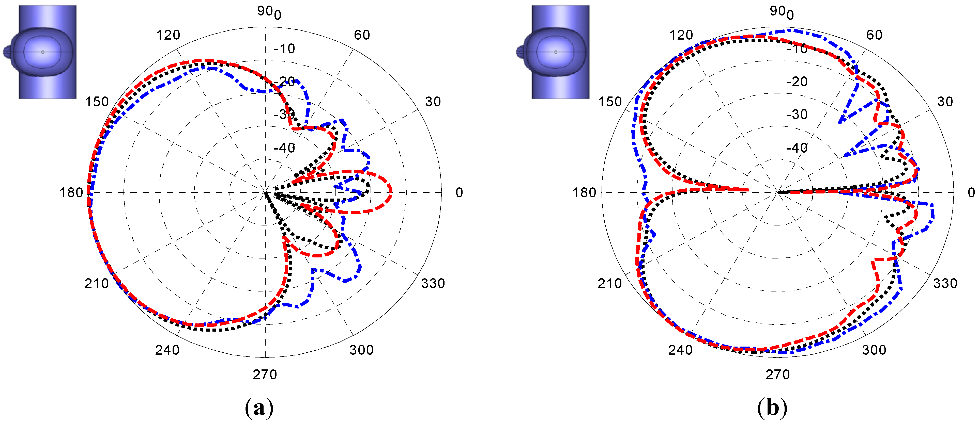
3. Comparison between Simulation and Measurement Results

Figure 7, Figure 8 and Figure 9 show, the co- and cross-polar H-plane cut radiation patterns of the AUT obtained from simulation and measurements with an optical fibre and with a metallic coaxial cable, for 2.4, 2.45, and 2.5 GHz, respectively. Note that the red dashed line represents the simulation results, the black dotted line represents the measurement results using an optical fibre, and the blue dash-dot line is for the measurement results using a metallic coaxial cable. A diagram of the AUT structure is presented at the top-left corner of each plot to show its orientation with respect to the plotted axes.
Good agreement is observed between the simulation and measurement using the optical fibre whereas the results obtained for measurements using the metallic coaxial cable clearly indicate the distortion to the AUT radiation pattern due to the effect of the unwanted common mode current on the cable. There is a slight discrepancy in the radiation pattern in the hemi-sphere at the back of the anthropomorphic phantom (i.e., between 0° to 90° and 270° to 360°) between the simulation and the measurement using the optical fibre. This cannot be attributed to the measurement error, which is estimated to be equivalent to an error signal of −30 dB below the pattern peak but is believed to be due to inhomogeneity of the anthropomorphic phantom properties that could not be modelled accurately.
Figure 7. The H-plane cut radiation pattern of the antenna under test (AUT) measured at 2.4 GHz: (a) co-polar field component; and (b) cross-polar field component.
Electronics 03 00462 g007
Figure 8. The H-plane cut radiation pattern of the AUT measured at 2.45 GHz: (a) co-polar field component; and (b) cross-polar field component.
Electronics 03 00462 g008
Figure 9. The H-plane cut radiation pattern of the AUT measured at 2.5 GHz: (a) co-polar field component; and (b) cross-polar field component.
Electronics 03 00462 g009

4. Conclusions

In this paper, a study into using a non-invasive optical fibre link for radiation pattern measurements of an electrically small DRA body-worn antenna has been presented. A solid anthropomorphic phantom was employed to minimize the measurement uncertainty. The measured results using the optical fibre link were validated with numerical simulation and measurements using a metallic coaxial cable. From the results, one can see the huge effect that lossy human tissue has on the electrically small DRA.
The measurement of the AUT showed a dramatic improvement in the pattern measurement when the metallic coaxial cable is replaced by an optical fibre. The numerical and experimental results using an optical fibre or a metallic coaxial cable were compared. Good agreement was found between the numerical results and the optical fibre measurement, which strongly demonstrated the improved measurement accuracy achieved by using an EO transducer to measure body-worn devices via optical fibre.

Acknowledgments

This work was supported by the 2011–2014 Physical Programme of the National Measurement Office, an Executive Agency of the UK Department for Business, Innovation and Skills (BIS), under Project 114792. Lawrence Rosenfeld was supported by the Institute of Physics (IOP) under a Top 40 Work Placements 2013 summer internship scheme. Our acknowledgements to Masayuki Kimura and Ryuji Osawa of Seikoh-Giken who continued development of the OEFS system and Erdem Ofli of SPEAG who provided the CAD model for the head phantom. The authors wish to acknowledge the loan of the DRA by Tim Palmer of Antenova Ltd., Andrew Gregory for measuring the solid anthropomorphic phantom, David Gentle, Phillip Miller, Ralf Mouthaan, and Benjamin Loader for their technical support and advice.

Author Contributions

Tian Hong Loh designed research, performed measurements, wrote the entire text, performed data analysis, interpreted results, and revised the manuscript; David Cheadle performed measurements and data analysis; Lawrence Rosenfeld contributed to numerical simulation, data analysis and drew the figures. Both David Cheadle and Lawrence Rosenfeld reviewed the articles.

Conflicts of Interest

The authors declare no conflict of interest.

References

  1. Salvado, R.; Loss, C.; Gonçalves, R.; Pinho, P. Textile Materials for the Design of Wearable Antennas: A Survey. Sensors 2012, 12, 15841–15857. [Google Scholar] [CrossRef] [PubMed]
  2. Kuhn, H.H.; Child, A.D. Electrically Conducting Textiles. In Handbook of Conducting Polymers, 2nd ed.; Skotheim, T.A., Elsenaumer, R.L., Reynolds, J.R., Eds.; Marcel Dekker: New York, NY, USA, 1998; pp. 993–1104. [Google Scholar]
  3. Wang, Z.; Zhang, L.; Volakis, J.L. Textile Antennas for Wearable Radio Frequency Applications. Text. Light Ind. Sci. Technol. J. 2013, 2, 105–112. [Google Scholar]
  4. Wearable Electronics and Photonics; Tao, X.M. (Ed.) Woodhead Publishing Ltd and CRC Press LLC: Boca Raton, FL, USA, 2005; pp. pp. 1–12 and pp. 177–197.
  5. Wearable Monitoring Systems, 1st ed.; Bonfiglio, A.; de Rossi, D. (Eds.) Springer: New York, NY, USA, 2011; pp. 165–252.
  6. Antennas and Propagation for Body-Centric Wireless Communications, 2nd ed.; Hall, P.S.; Hao, Y. (Eds.) Artech House: London, UK, 2012; pp. 151–240, 271–278.
  7. Wireless Body Area Networks: Technology, Implementation, and Applications; Yuce, M.; Khan, J. (Eds.) Pan Stanford Publishing: Singapore, Singapore, 2011; pp. 4–6.
  8. Special Issue on Antennas and Propagation on Body-Centric Wireless Communications; Hall, P.; Hao, Y.; Ito, K. (Eds.) IEEE Transactions on Antennas and Propagation: Piscataway, NJ, USA, 2009; p. 57.
  9. Li, H.-B.; Yazdandoost, K.Y.; Zhen, B. Wireless Body Area Network; River Publishers: Aalborg, Denmark, 2010; Chapter 3. [Google Scholar]
  10. Kennedy, T.F.; Fink, P.W.; Chu, A.W.; Champagne, N.J.; Lin, G.Y.; Khayat, M.A. Body-worn E-textile antennas: The good, the low-mass, and the conformal. IEEE Trans. AP 2009, 57, 910–918. [Google Scholar] [CrossRef]
  11. Fujii, K.; Takahashi, M.; Ito, K. Electric field distributions of wearable devices using the human body as a transmission channel. IEEE Trans. AP 2007, 55, 2080–2087. [Google Scholar] [CrossRef]
  12. Sabban, A. Wearable Antennas for Medical Applications. In Advancement in Microstrip Antennas with Recent Applications; Kishk, A., Ed.; Chapter 13; InTech: Rijeka, Croatia, 2013; pp. 305–335. [Google Scholar]
  13. Soh, P.J.; Vandenbosch, G.; Yan, S. Made to be worn. Electron. Lett. 2014, 50, 420. [Google Scholar]
  14. Bodymedia Body Monitoring Technologies. Available online: www.bodymedia.com (accessed on 15 July 2014).
  15. BodyLAN—FitSense Technology. Available online: http://devel.fitsense.com/b/BodyLAN.asp (accessed on 15 July 2014).
  16. IEEE 802.15 Working Group for WPAN. Available online: www.ieee802.org/15/ (accessed on 15 July 2014).
  17. IEEE 802.11 Working Group for WLAN. Available online: http://grouper.ieee.org/groups/802/11/ (accessed on 15 July 2014).
  18. Conti, M. Wireless Communications and Pervasive Technology. In Smart Environments: Technologies, Protocols, and Applications; Cook, D.J., Das, S.K., Eds.; John Wiley & Sons: New York, NY, USA, 2004; pp. 63–100. [Google Scholar]
  19. Salonen, P.; Rahmat-Samii, Y.; Kivikoski, M. Wearable antennas in the vicinity of human body. IEEE Antennas Propag. Soc. Int. Symp. 2004, 1, 467–470. [Google Scholar]
  20. Loh, T.H.; Matthews, J.; Alexander, M.; Knight, D.; Mouthaan, R.; Loader, B. Measurements of Body Wearable Antennas. In Presented at IET Seminar on Antenna and Propagation for Body-Centric Wireless Communications, London, UK, June 2011.
  21. Duan, Z.; Linton, D.; Scanlon, W.; Conway, G. Using EBG to Improve Antenna Efficiency in Proximity to the Human Body; IET Seminar on Wideband, Multiband Antennas and Arrays for Defence or Civil Applications: London, UK, 2008; pp. 173–180. [Google Scholar]
  22. Alabidi, E.S.; Kamarudin, M.R.; Rahman, T.A.; Khalily, M.; Josoh, M. Radiation characteristics improvement of monopole antenna above glass substrate for WBAN applications. Life Sci. J. 2014, 11, 124–131. [Google Scholar]
  23. Dey, S.; Dipto, N.A.; Rafin, M.A.-R.; Mojumder, S.; Shahrin, M. Design of wearable antenna system on different materials & their performance analysis at the off and on body environment in terms of impedance matching and radiation characteristics. Am. Acad. Sch. Res. J. 2013, 5, 181–192. [Google Scholar]
  24. Ammann, M.J.; Curto, S.; Bao, X.L.; McEvoy, P. Antenna Design Considerations for High Specific Absorption Rate in Local Hyperthermia Treatment. IEEE Antennas Propag. Soc. Int. Symp. 2008, 1–4. [Google Scholar]
  25. Loh, T.H.; Alexander, M.; Miller, P.; Betancort, A.L. Interference minimisation of antenna-to-range interface for pattern testing of electrically small antennas. In Proceedings of the 4th European Conference on Antennas and Propagation, Barcelona, Spain, 11–16 April 2010.
  26. Vorobyov, A.V.; Zijderfeld, J.H.; Yarovoy, A.G.; Ligthart, L.P. Impact Common mode currents on miniaturized UWB antenna performance. In Proceedings of The European Conference on Wireless Technology, Paris, France, 3–4 October 2005; pp. 285–288.
  27. Abuelhaija, A. Development of a noval Switched Beam Antenna for Communications. Master Thesis Presentation; Duisburg-Essen University: Duisburg, 2010. Available online: http://hft.uni-duisburg-essen.de/arbeiten/Vortrag_MA_Abuelhaija_Ashraf.pdf (accessed on 15 July 2014).
  28. Enprobe GmbH. Available online: http://www.enprobe.de/products_FO-Links.htm (accessed on 15 July 2014).
  29. Schmid & Partner Engineering AG. Available online: http://www.speag.com/products/em-phantom/ (accessed on 15 July 2014).
  30. Clarke, R.N.; Gregory, A.P.; Hodgetts, T.E.; Symm, G.T.; Brown, N.M. Microwave measurements upon uniaxial anisotropic dielectrics—Theory and practice. In Proceedings of the British Electromagnetic Measurements Conference (BEMC) 95–22, Malvern, UK, 7–9 November 1995.
  31. Computer Simulation Technologies. Available online: http://www.cst.com (accessed on 15 July 2014).

