1. Introduction
Recently, extensive studies of micro air vehicles (MAVs) driven by electric propellers have been carried out. Compared with unmanned air vehicles for military use, MAVs are expected to decrease the total cost of flight system. In addition, the MAV has to remain stable enough so as to serve as a flight mission platform and easy enough to operate with minimal training [
1,
2,
3].
In low-speed flight conditions of MAV, the rotational speed of the propeller is the major factor of thrust force [
4]. Hence, it is essential to control the rotor speed accurately in order to ensure good flight performance of the MAV. However, most such MAVs have not been equipped with any rotational speed measurement sensors to meet overall size, weight, and cost reduction requirements. Thus, developing a kind of soft sensor is a good method to obtain the accurate speed information of electric propellers.
A soft sensor is a kind of generalized sensor which plays an estimation role of variables, especially when they cannot be measured by normal hardware sensors directly or the cost and difficulty limits the use of hardware sensors. The core of a soft sensor is a mathematical model to realize optimal estimation of primary process variables (also called dominant variables) by secondary process variables (also called assistant variables) [
5,
6]. A soft sensor which is based on a certain mathematical model could be designed if the model describes the process adequately accurately. Therefore, if a model-based soft sensor relies on a detailed model which is a computational enhancement, then the soft sensor can be applied to a real-time application [
7].
Some proposals to solve the measurement problems have, to date, been made. The speed sensors based on artificial neural networks are designed to estimate the motor speed, which are, however, excessively dependent on much external information such as motor load, armature current, shunt resistance, and armature voltage. Even worse, some information is difficult to obtain in most cases [
8,
9]. An estimation method which takes measured terminal voltages and currents as input is proposed. This method is based on the model reference adaptive identification to achieve moderate bandwidth speed estimation, but it has also shown some limitations in accuracy at a low speed range [
10]. The soft sensors based on various observers, such as an adaptive sliding mode observer [
11], an adaptive nonlinear state observer [
12], an extended Kalman estimator [
13], and a nonlinear observer [
14], can be particularly useful for solving rotational speed measurement problems. Nevertheless, they easily fail to achieve a satisfactory performance at a low speed range or in the presence of parametric uncertainties, and some of them are also largely dependent on varies kind of information which cannot be detected easily.
This study aims to develop a soft sensor for the rotational speed measurement of an electric propeller. An adaptive learning algorithm is derived for the soft sensor by using Popov hyperstability theory, based on which a one-step-delay adaptive learning algorithm is further proposed to solve the implementation problem of the soft sensor. The algorithm only employs the input signal and the commutation instant of the motor, both of which are easily available. A series of bench tests have been carried out which proved the learning performance and accuracy of the soft sensor.
The structure of this paper is as follows:
Section 2 discusses the rotational speed measurement issues of MAV.
Section 3 introduces the modeling progress of soft sensor and the adaptive learning algorithm.
Section 4 presents all test results of experiments. In the end, conclusions are summarized in
Section 5.
2. Rotational Speed Measurement Problems of the Prototype MAV
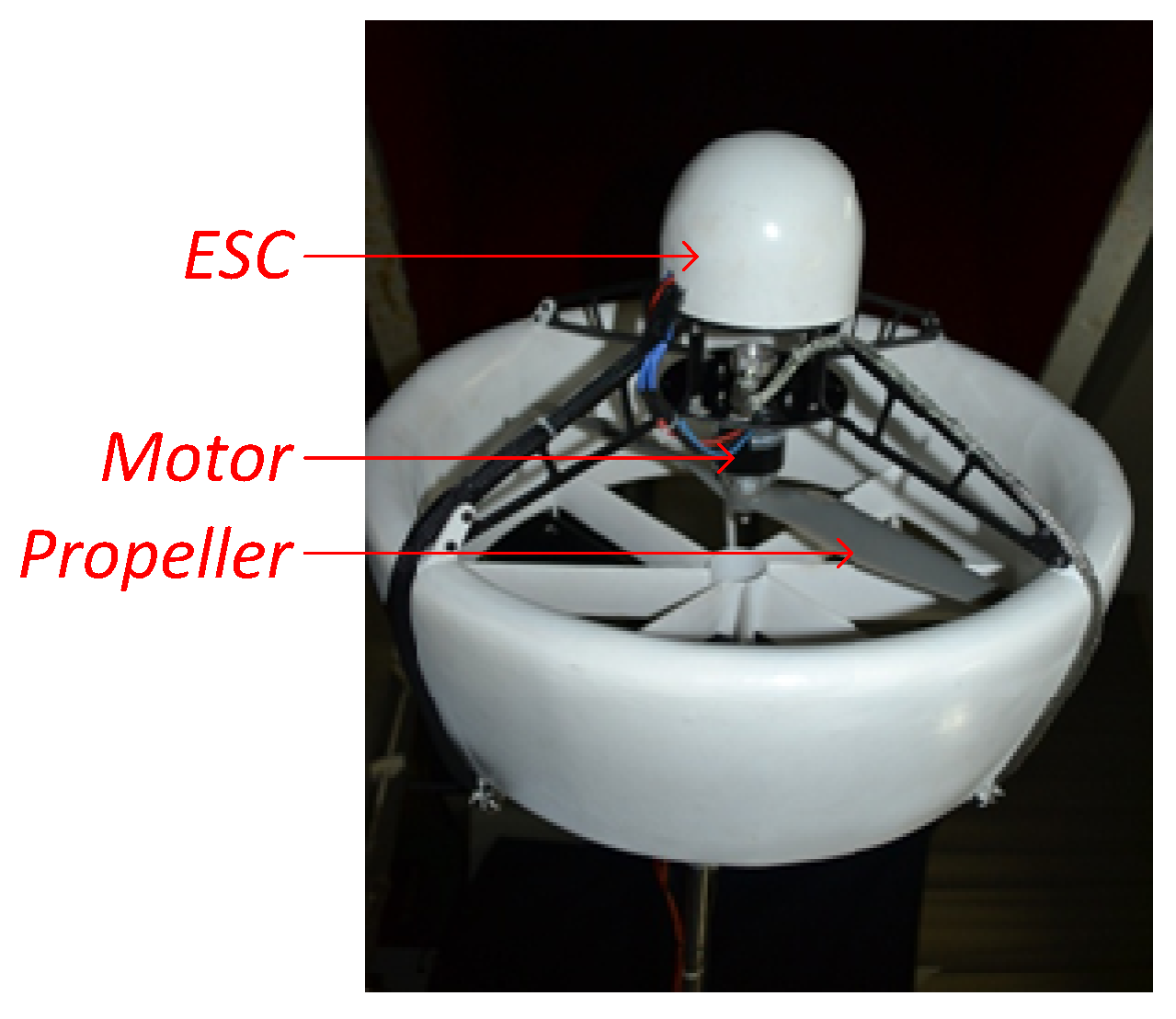
Figure 1 shows the prototype electric MAV. The MAV flight/thrust system includes a high-efficiency lithium battery, a brushless DC motor with an electronic speed controller (ESC), and a propeller. The motor and propeller system is installed in the center of the fuselage in order to provide lift force to raise the MAV. Under the propeller, there are four rotating vanes arranged as a cross which realize the flight control of roll, yaw, and pitch. Rotational speed sensors are expected to be applied to the MAV so as to improve the flight performance, including stability, reliability, and flight dynamics.
It is, however, noted that until recent times most such MAVs are not equipped with any physical sensors to measure the rotational speed of the propeller for the automatic flight control system. It is mainly because this may significantly add weight to MAVs and increase the power consumption, which is inadmissible for such small, light-weight, low-power, and low-cost MAVs. Without a rotational speed test measurement, the propeller speed can only be controlled in open-loop mode, which results in uncertainty of speed fluctuate and bad overall performance especially in bad environments. The purpose of the paper is to develop a kind of soft sensor which can precisely measure the rotational speed of the electric propeller.
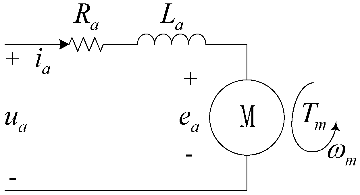
Compared with brushed motors, the brushless motor generates higher toque and speed with the same motor weight. The three-phase input driving voltage of the brushless motor is generated by the ESC with pulse width modulation technology. The power signals alternate the polarity of the electromagnets on the motor stator which keep the rotor spinning. The analysis of the basic principle model of the brushless DC motor is crucial for the preliminary development of the soft sensor, based on which a proper soft sensor structure can be obtained. As is shown in
Figure 2, the schematic diagram of the rotor conveys specific relationship of electrical constitutions, where the no-load current is known and is compensated by the ESC.
The equations that describe the electrical components of the DC motor are as follows [
15]:
where
represents armature coil resistance,
represents armature current,
represents armature coil inductance,
represents back electromotive force,
represents motor armature voltage,
represents voltage constant,
represents torque constant,
represents torque generated by the motor, and
represents rotational speed of the motor.
The propeller produces a torque [
16]:
where
(Nms
2/rad
2) is the propeller torque constant,
(Nm) is the propeller torque, and
(rad/s) is the rotational speed of the propeller.
We assume that the propeller is installed on the propeller shaft which is rigidly connected with the drive shaft of the motor. Under this assumption, the following conditions hold:
Substituting Equations (2) and (3) into Equation (1) yields:
where
and
. Obviously, it is not possible to obtain an explicit expression or a precise value of
, mainly because the coefficients of the equation is not available and Equation (4) is a nonlinear differential equation.
As for the rotational speed system in Equation (4), some reasonable assumptions must be made preliminarily to simplify the design of the soft sensor as follows:
Furthermore, the commutation interval angle of the motor is expressed as follows:
where
is the actual rotational angle;
and
are the
and
commutation instant, respectively, both of which are available from the ESC;
is the number of pole pairs of the motor.
Remarks
(1) The nonlinear differential equation of the brushless DC motor makes a number of simplifying assumptions based on the fact that the propeller, together with the motor, is in the range of operation in which the rotational speed remains high enough to lift the MAV.
(2) The changes in the efficiencies of the propeller and the motor are generally small for most such electric MAVs under the above operating condition, as demonstrated in
Section 4. Therefore, we do not take these factors into consideration in the model for simplification.
(3) The model assumes the voltage
can be changed instantaneously and continuously, which directly determines the model structure. As mentioned above, the voltage is generated by the ESC. In most cases, however, the time response of the ESC is generally so fast that the dynamics can be thoroughly ignored in the model [
17].
It is finally notable that the resulting model and the assumptions given in Equations (4)–(6) can help us define the model of the soft sensor, and derive a learning algorithm for the soft sensor in the following section.
3. Soft Sensor Modeling and the Adaptive Learning Algorithm
We present the model of the soft sensor in the same form as Equation (4):
where
denotes the output of the soft sensor;
, and
are the parameters of the soft sensor, which need to be tuned adaptively in the full adaptation process.
The measurement error between the outputs of the rotational speed system and soft sensor is then given by:
Substituting Equations (4) and (7) into Equation (8) yields:
where
and
. It should be noted that the differential equation of the measurement error on the left-hand side is expressed in a linear form, which is very useful to derive an adaptive learning algorithm for the soft sensor.
It is well-known that this system is asymptotic hyperstable if the backward non-linear block satisfies the Popov integral inequality and the forward linear block satisfies a positive real condition [
18]. The error system described by Equation (9) is then hyperstable while the learning algorithm is chosen as follows:
where
, and
are optional positive numbers. Although the derived algorithm can ensure that
asymptotically converge to
, it is generally impractical because the measurement error
is unavailable in this case. Therefore, further research is required to solve the implementation problem of the adaptive learning algorithm.
In general, and are continuous, and is integrable on . Now consider the following condition:
(A1) does not change sign on .
Then according to the second mean value theorem for definite integrals, there exists
such that, under the condition (A1):
where:
and where
denotes the virtual rotational angle of the soft sensor.
The adaptive learning algorithm can, therefore, be rewritten as:
However, the modified adaptive learning algorithm is still incomputable because and cannot be obtained explicitly by analytical methods.
To illustrate further, consider the following conditions:
(A2) does not change sign on ,
(A3) does not change sign on .
As is well known, the correct determination of the gradient direction of adjustable parameters is particularly important to guarantee the stability of the proposed algorithm. Therefore, under the conditions (A2) and (A3), the adaptive learning algorithm for the soft sensor can further be approximately modified as follows:
Remarks
(1) In practice we can assume that the condition A1 holds true at time instant if , , , and are strictly monotonic.
(2) It is important to note that and are available at any given time. Thus, the conditions (A2) and (A3) can be easily checked using the observation data.
(3) From Equations (6), (12), and (13), we can also conclude that the proposed adaptive learning algorithm for the soft sensor only depends on the actual rotational angle at every commutation instant from the ESC, and is independent of any particular hardware platform.
(4) It is noted, in addition, that in the presence of the measurement error of the commutation instant, the soft sensor can provide a more accurate and continuous estimation of the rotational speed when compared to a simple discrete rotational speed estimation based on the commutation instant from ESC only, mainly because, on one hand, the effect of the measurement error on the former is weakened through the parameters of the soft sensor, as shown in Equation (15) and, on the other hand, the effect of the measurement error on the latter depends on the commutation interval, and is significant, especially when the rotational speed is high.
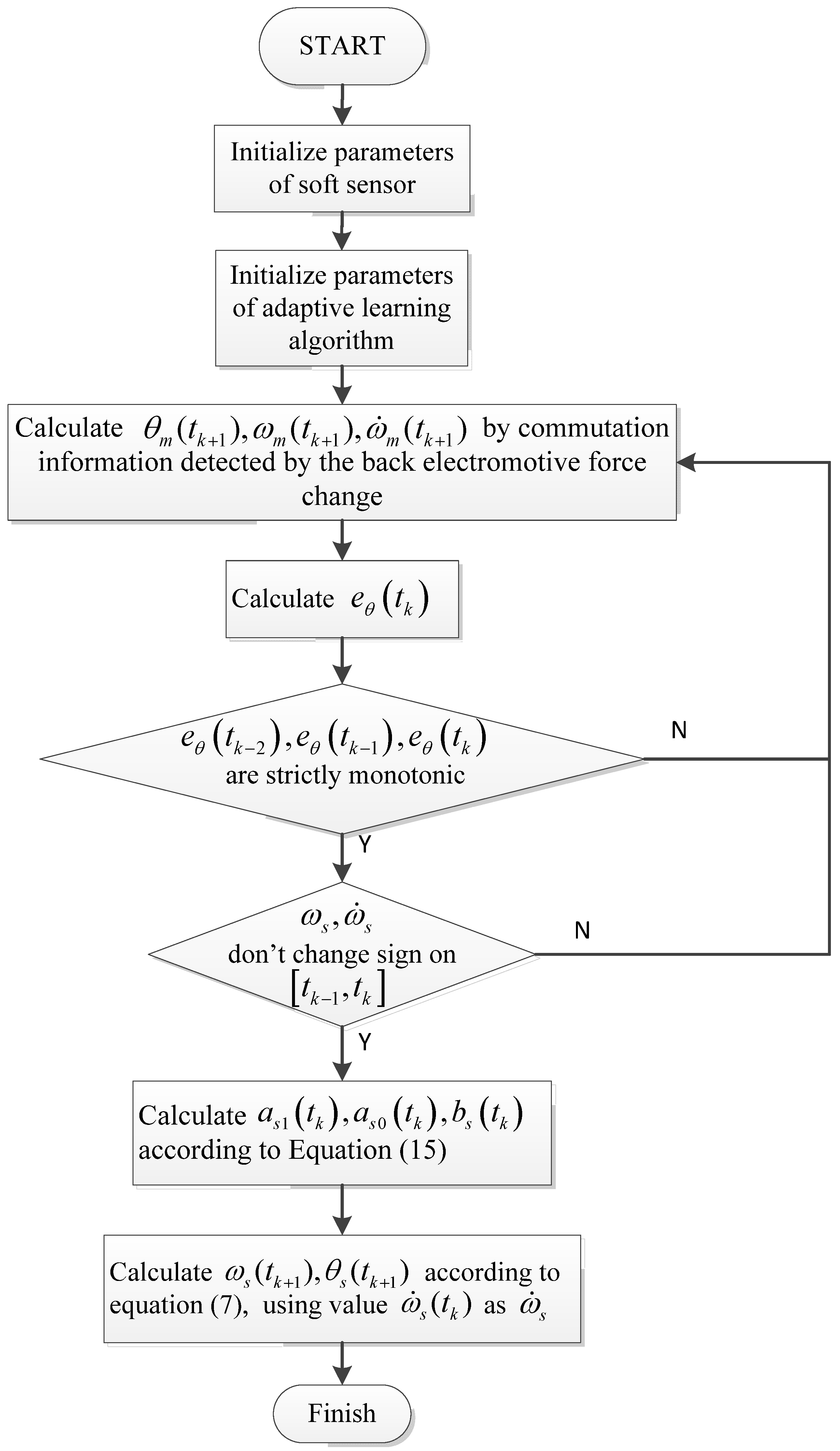
According to the discussion made so far, a one-step-delay adaptive learning algorithm is presented for the soft sensor to further simplify the algorithm implementation. The calculation steps are described in algorithm 1 and the flowchart is shown in
Figure 3.
| Algorithm 1: One-step-delay adaptive learning algorithm |
| At time instant , |
| Input: |
| 1. |
| 2. |
| 3. |
| Output: |
| Steps: |
| 1. if aren’t strictly monotonic, then End; else Continue |
| 2. if changes sign on , then End; else Continue |
| 3. if changes sign on , then End; else Continue |
| 4. Calculate according to Equation (15), End |
It is important to note that the one-step-delay adaptive learning algorithm can, in practice, avoid the complication that we have to obtain a priori data .
4. Experimental Tests
In this part, the experimental platform is first introduced. Then, experimental results with necessary discussions are presented.
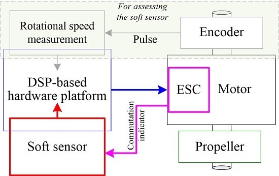
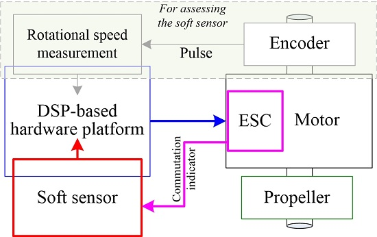
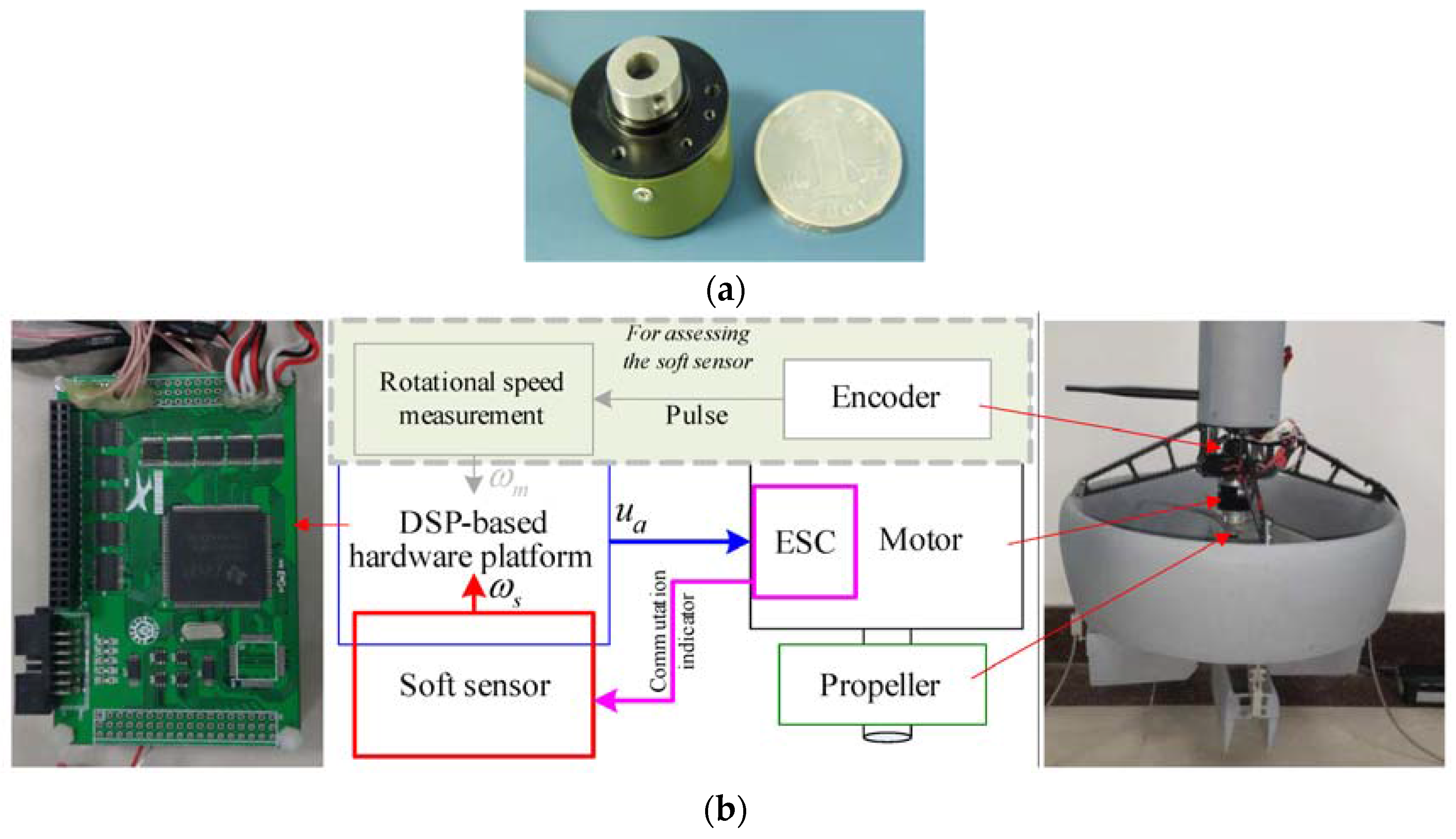
The software of the soft sensor runs on a DSP-based hardware platform (TI TMS320F28335), which is good at processing complex numeral calculations and providing accurate time information. The ESC of the motor can send a trigger signal to the soft sensor at the commutation instant. A subminiature, high-resolution rotary encoder with a resolution of 20″, shown in
Figure 4a, is installed on another end of the transmission shaft. The rotational speed of propeller can be measured directly by analyzing the timing between the output pulses of the encoder, since the propeller rotates in a single direction. Note that the rotational speed from the encoder is only used to assess the soft sensor. The experiment system is shown in
Figure 4b.
The predefined parameters are chosen as follows:
- (1)
Initial values of the soft sensor: ;
- (2)
Adaptive learning algorithm: ;
- (3)
Pole pairs of the rotor: .
We then assess the learning performance and the accuracy of the soft sensor by comparing the outputs of the sensor with the unbiased measurements generated by the encoder mainly within the working speed range of the propeller.
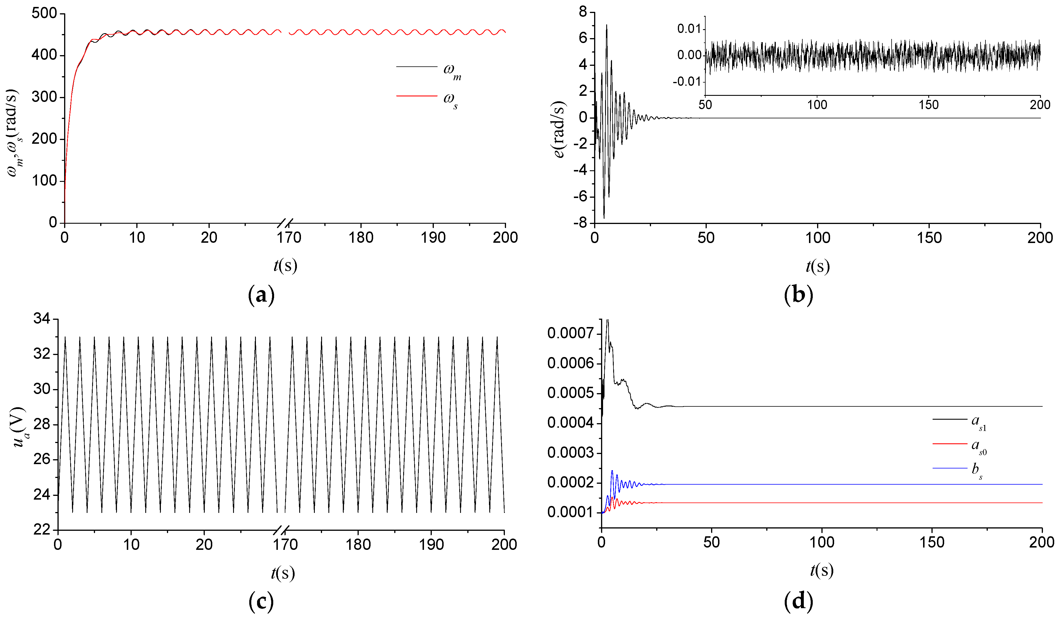
Figure 5 shows the experimental results of the soft sensor for the input triangle wave. It is illustrated from
Figure 5a,b that the soft sensor can achieve good measurement performance within 25 s even without any a priori information about the behavior of the rotational speed system. The measurements of the soft sensor can then match approximately with the measurements generated by the high-resolution encoder, and the measurement error finally maintains within the range of 0.005 rad/s. As shown in
Figure 5d, the parameter of the soft sensor has a good astringency property. However, it is worth pointing out that the soft sensor stops learning after 25 s, in this case, because of the measurement noise of the commutation instant from the ESC, which results in a possibly early termination of the learning algorithm in Step 1.
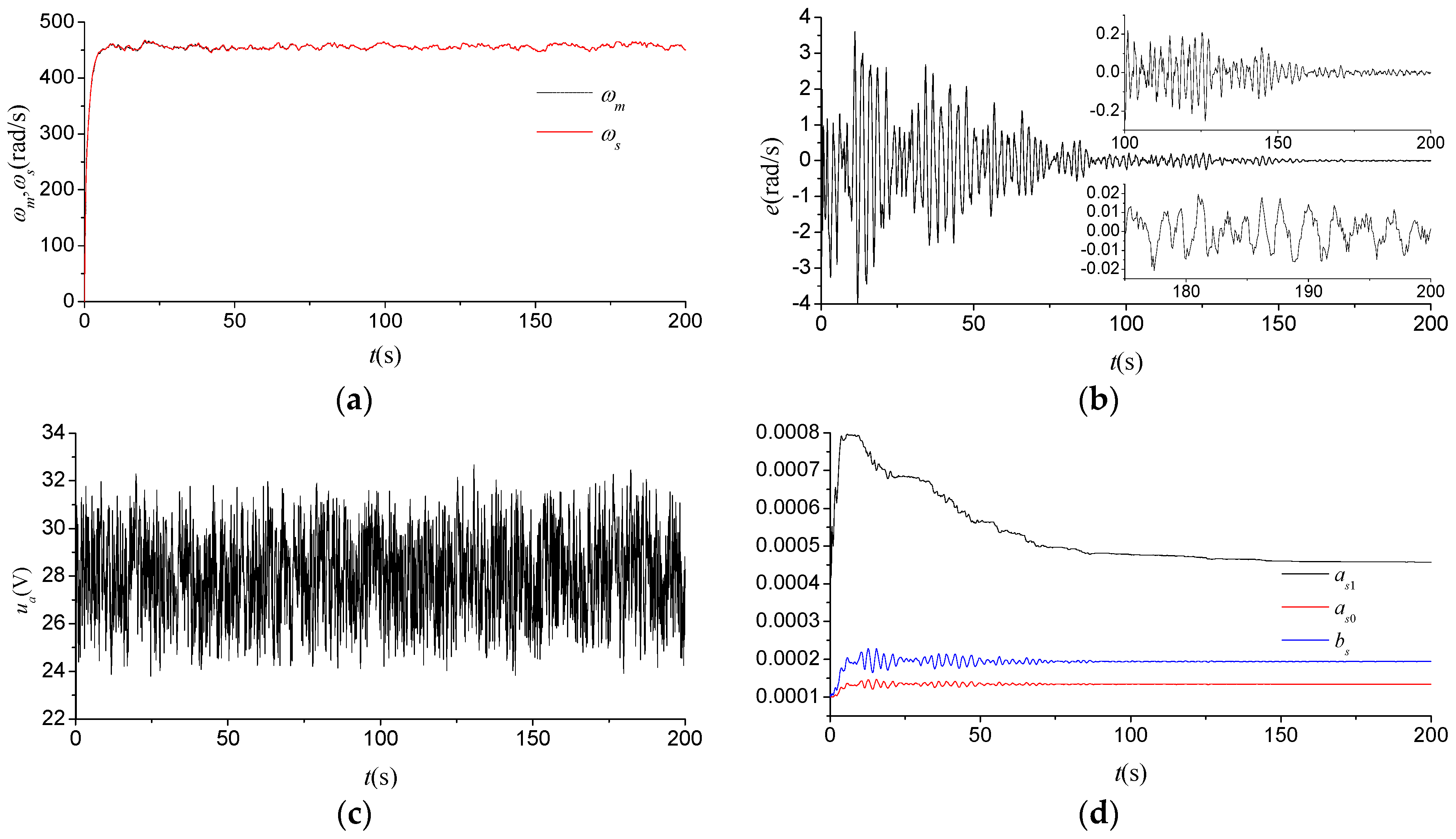
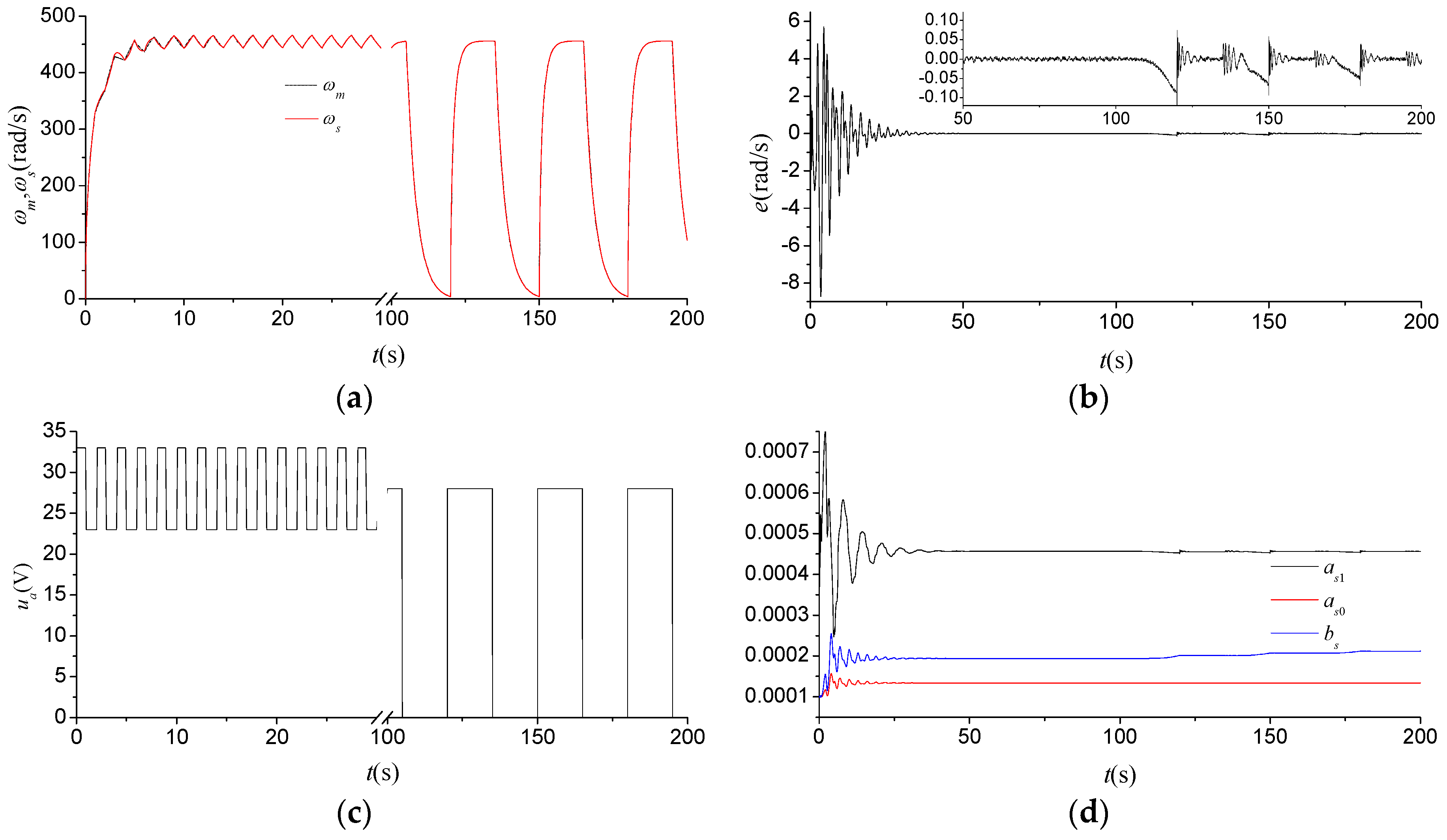
Figure 6 indicates the experimental results of the soft sensor for the input square wave, which demonstrates that the learning performance and the accuracy of the soft sensor remain approximately unchanged in the first 100 s when compared to the results shown in
Figure 5. However, the soft sensor can still achieve good measurement performance for the aggressive maneuvers in next 100 s in spite of the significant increase in measurement error, which have once again verified the performance and characteristics of the soft sensor within a wide range of rotational speeds. It is, however, notable that there is a converging trend of the measurement error from 100 to 200 s shown in
Figure 6b, which indicates that the significant increase in the measurement error can contribute to the learning performance of the soft sensor, as shown in
Figure 6d.
Figure 7 shows the flight test results of the soft sensor during the period from taking off to hovering about 5 m off the ground. As shown in
Figure 7b,d, the learning performance and the accuracy of the soft sensor deteriorate slightly in the initial stage of the adaptive learning process that lasts for a longer period of time. Most of the deterioration can be attributed to the increase in the noise component of the input signal from an altitude control-signal generator, as shown in
Figure 7c, because the increase can more easily result in a possibly early termination of the learning algorithm. Nevertheless, the measurement error can also converge gradually to an acceptable range after 150 s. The measurement accuracy of the soft sensor is expected to be better than 0.01 rad/s after 200 s, which is adequate enough to satisfy the application demands of the MAV.
It should be emphasized that, on one hand, given the original model parameters, the soft sensor can substantially realize an accurate measurement after a period of time and, on the other hand, the proposed adaptive learning algorithm can also guarantee the measurement performance of the soft sensor in the range of operation. Nevertheless, the measurement performance deteriorates slightly with the increase in the variation range of the rotational speed due to the influences of the nonlinear and uncertain factors mentioned above.

