1. Introduction
Around the world, through initiatives such as Industrie 4.0 in Germany, Industrial Internet in the USA, and Made in China 2025, there has been discussion of the directions the next generation of manufacturing will take. Common to all these discussions is the Internet of Things (IoT) where machines, factories, and infrastructure are connected through the internet. The Japanese government as well has recognized the necessity of IoT connectivity and methodologies to exploit it for Japanese industry [
1]. At this point in Japan, a great deal of connectivity has been achieved by large companies, although in Japan the term Information and Communication Technology (ICT) has been favored. However, smaller companies have not been able to introduce IoT technology because cost-effective technologies have not been available.
Radio frequency identification (RFID) is a well-known ICT technology that can automatically identify physical objects and people much like a barcode system. A large number of studies have appeared investigating RFID [
2], and RFID technologies have become indispensable in manufacturing, especially in production management. The use of RFID provides quick and accurate management of the flow of products [
3,
4].
In previous research, the concept of object-orientation was applied to RFID and named object-oriented RFID (OORFID) [
5]. By introducing the mechanism of inheritance to OORFID [
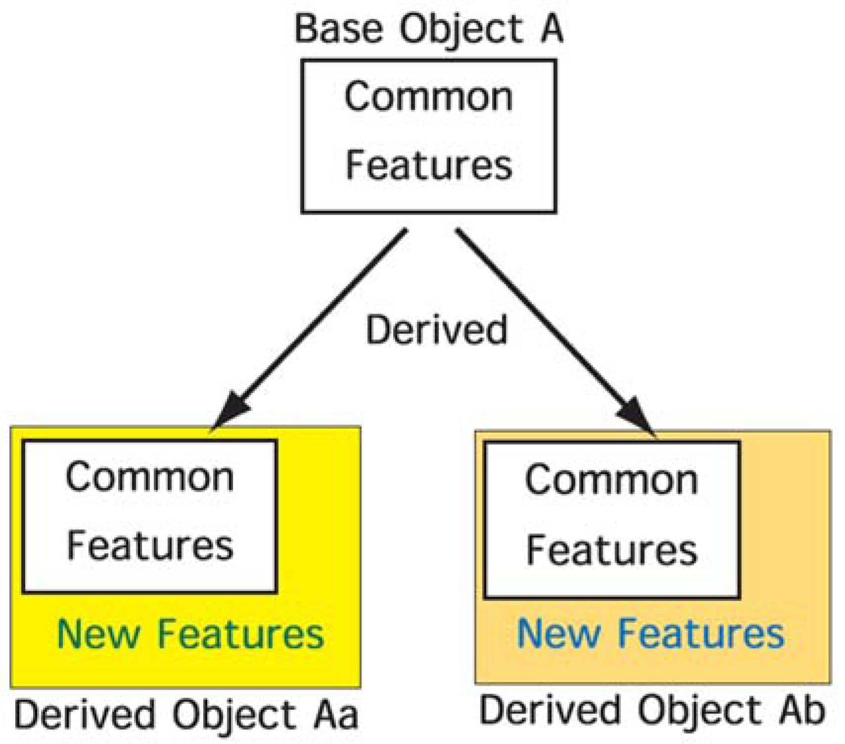
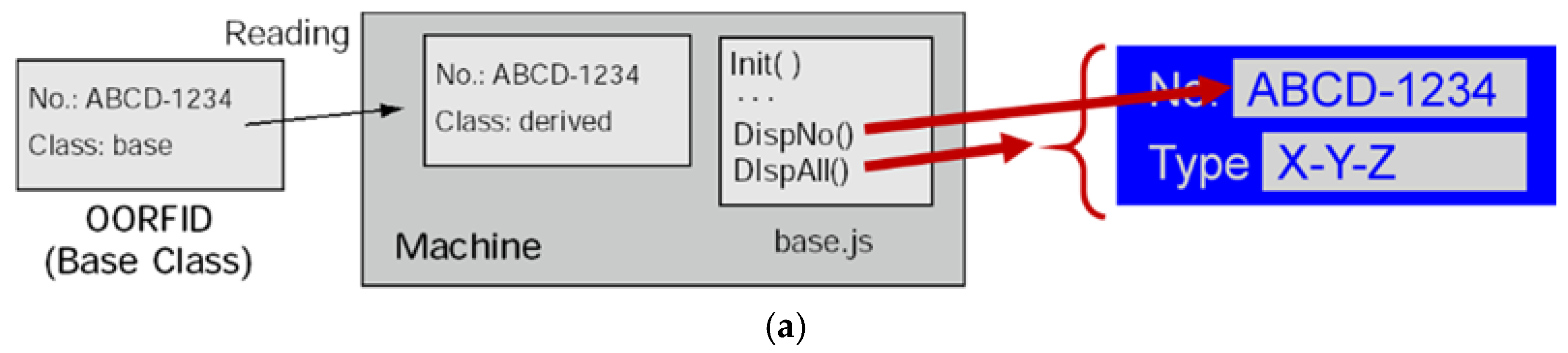
6], various kinds of OORFID tags can be managed with improved flexibility, and the RFID memory is also utilized more efficiently. Inheritance is a core technique in object-orientation and allows the reuse of information. As shown in
Figure 1, using the inheritance mechanism, a new object (derived object “Aa”) can be easily derived from a base object (“A”) and given new features. Similarly, a second derived object (“Ab”) can be created with a different set of new features added to the base object. Both objects Aa and Ab inherit common features from the base object.
In further research, polymorphism was realized using the inheritance mechanism [
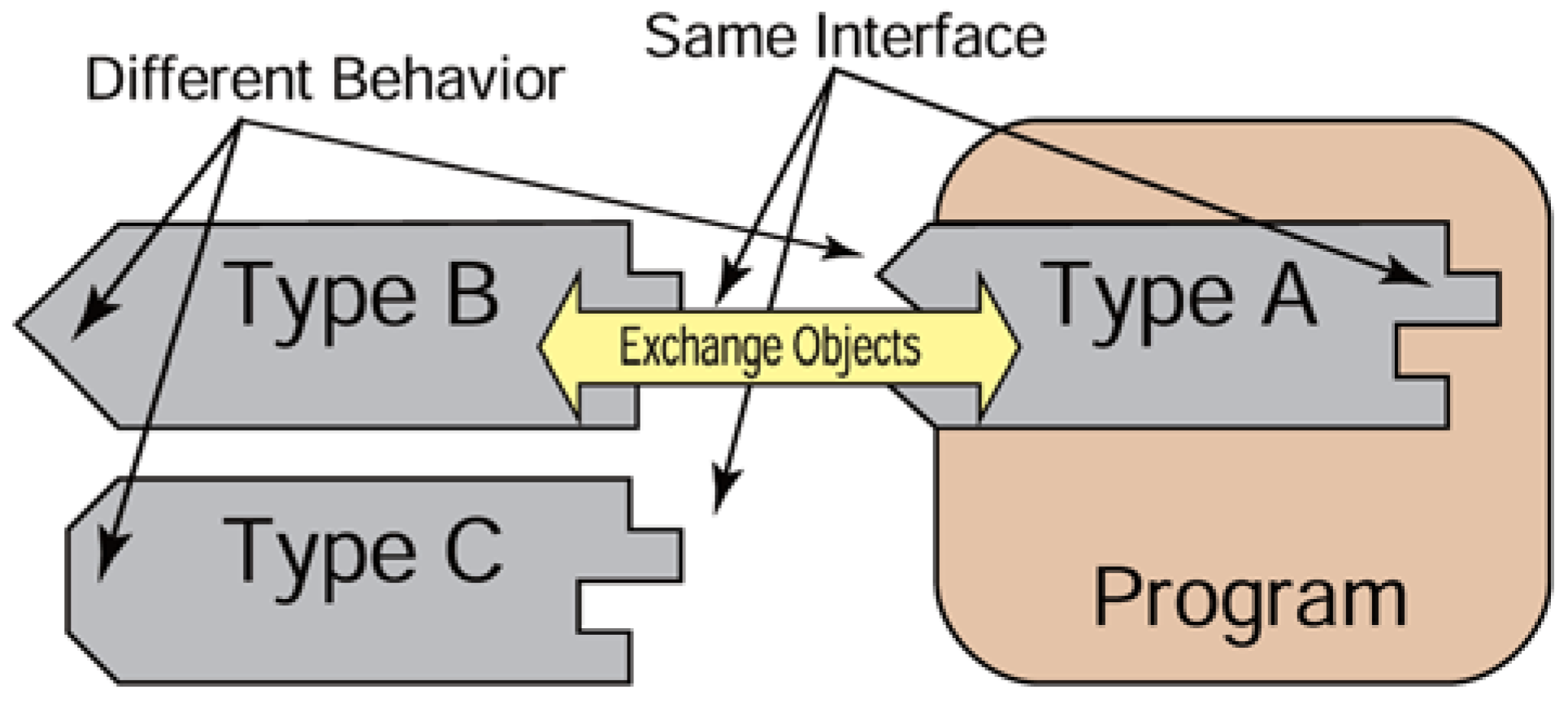
7]. Polymorphism is an important object-oriented paradigm and is the ability of “one type A to appear as and be used like another type B”. Objects of the same class have the same interface and behavior; however, if we use the inheritance mechanism, we can make objects that have the same interface (common feature) but different behavior (new feature) as in
Figure 2. To achieve polymorphism, we must make the objects from the base class or from a class that has inherited from the base class.
An RFID tag is usually used as a key to connect to a server, but it also can be treated as an object allowing the application of the mechanisms of inheritance and polymorphism. The objective of this research is to suggest a design concept that combines the IoT and OORFID. The IoT technology is used for collecting, analyzing, and managing data; the OORFID system is used for a control process in the manufacturing systems. In previous research [
5,
6,
7], it was shown that the OORFID system provides flexible management through the use of a variety of the OORFID tags. The current research attempts to introduce the OORFID into IoT systems to improve flexibility in manufacturing systems.
For the verification of this design concept, an experimental RFID-based manufacturing information system with an IoT element is redesigned. As a proof of concept, a scenario is assumed where mieruka is conducted to observe measurement values obtained from an IoT sensor. Following this scenario, the RFID-based manufacturing information system is redesigned to modify the system using the derived OORFID. As a result, it is shown that the OORFID controls the manufacturing information system—in particular, the communication with the IoT sensor.
2. IoT and OORFID
2.1. Internet of Things in Manufacturing System
The Japanese Government stated in the ICT white paper [
8] that IoT means that a multitude of things―not just conventional ICT devices like computers, smartphones, and tablets―will form part of the Internet by virtue of sensors and wireless communications. The IoT concept refers to a state where vehicles, white appliances, robots, facilities, and nearly all other things connect to the Internet and exchange information with each other. According to the concept, as things are converted into data and automation based on these data progresses, new added value will be generated.
In the IoT system, the various things are connected together. However, the connecting itself brings only a few advantages. It is very important how data is collected, processed, and used [
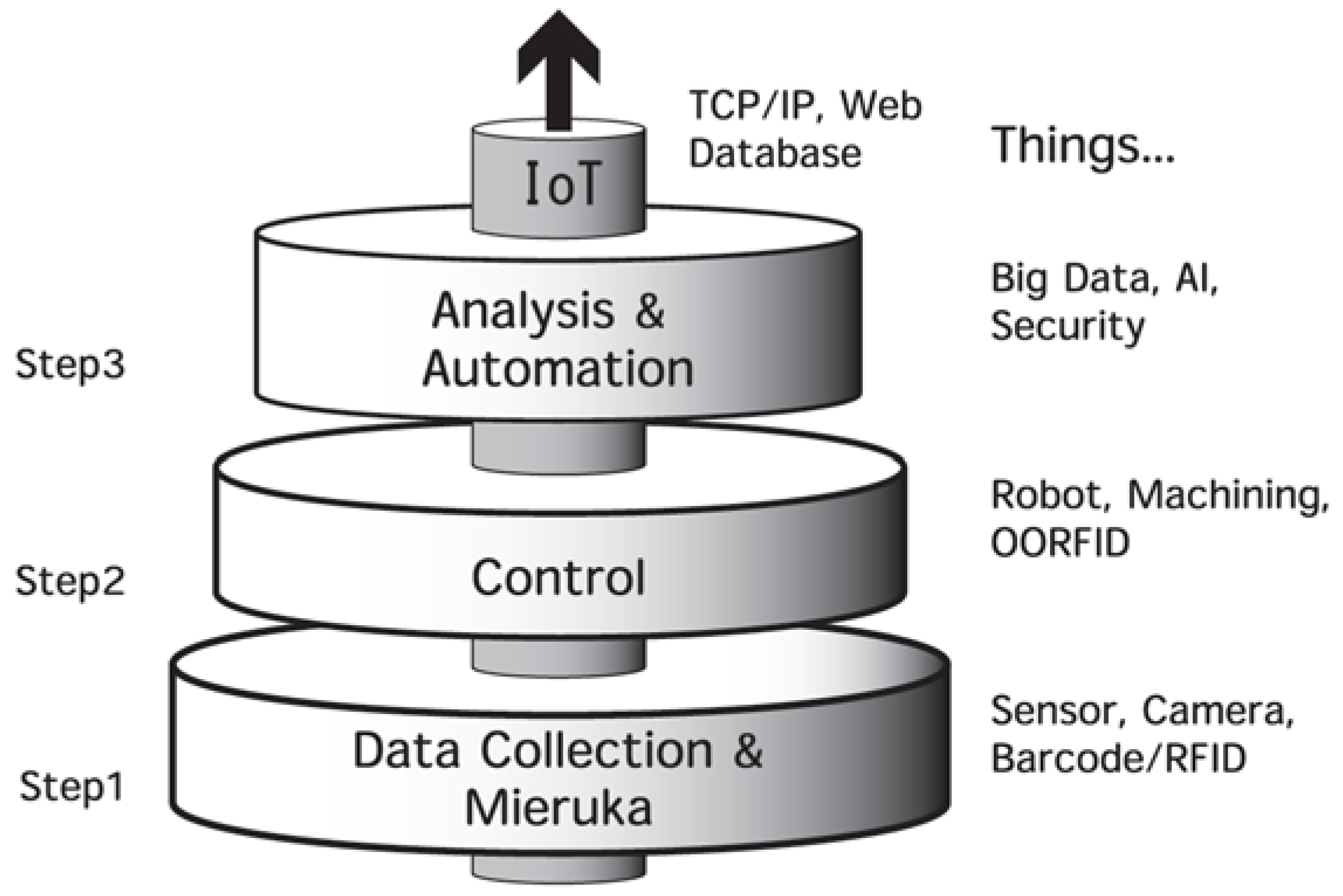
9]. The introduction of the IoT to the manufacturing systems has several steps [
10] as shown in
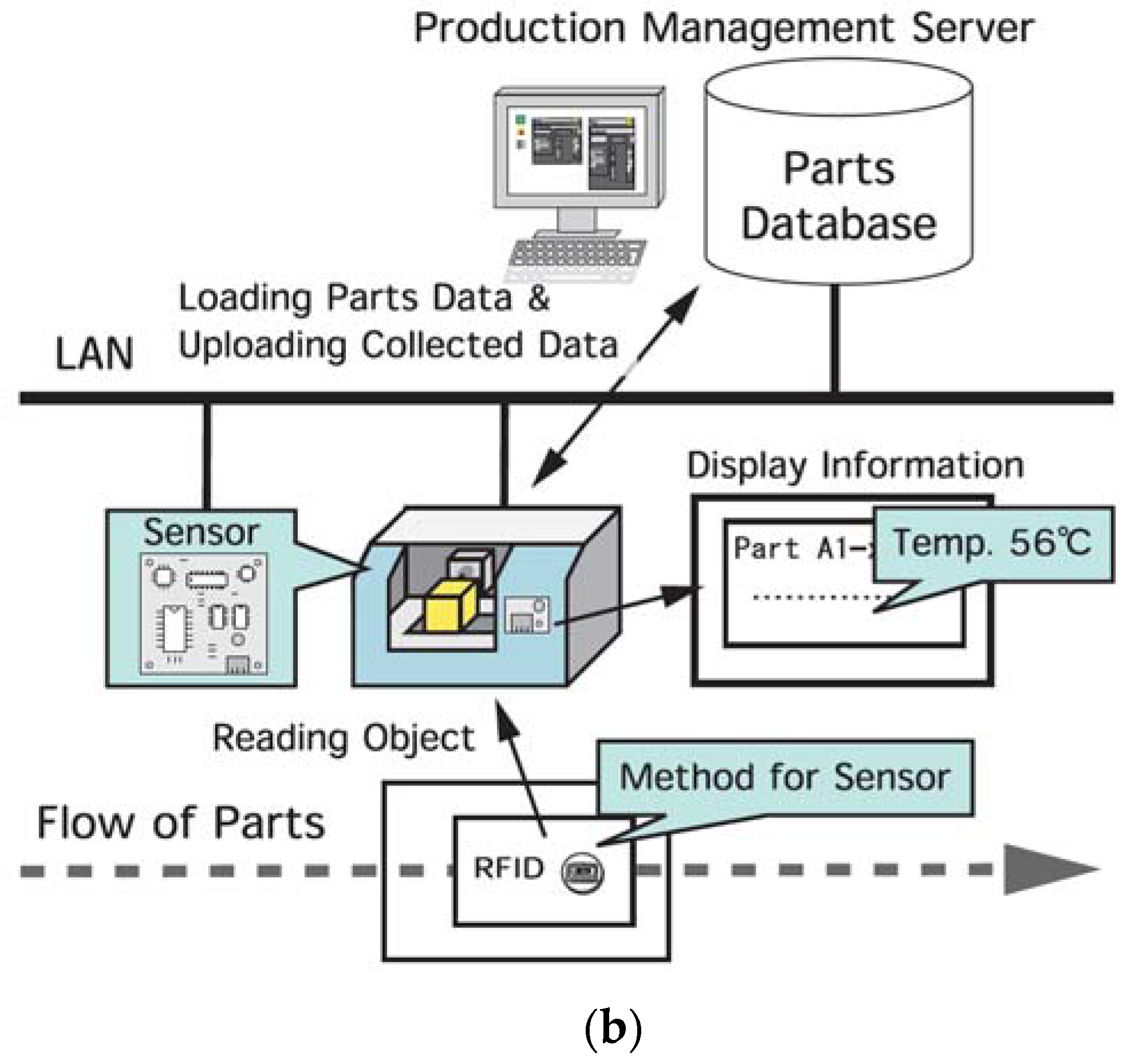
Figure 3. The first step is the data collection and mieruka. Mieruka is a part of kaizen, and it is the collection of the various data from the IoT devices in order to identify problems and bring them to the foreground. This may use an RFID system to collect data. It also includes a monitoring function. The second one is control. This means controlling devices such as machines and robots through the network. The last one is analysis for automation, which in turn means analyzing the data (sometimes big data) that has been collected to manage the manufacturing process automatically, perhaps by using AI (artificial intelligence). Moreover, the security of information must be considered in the automated control.
2.2. OORFID in Contrast with RFID
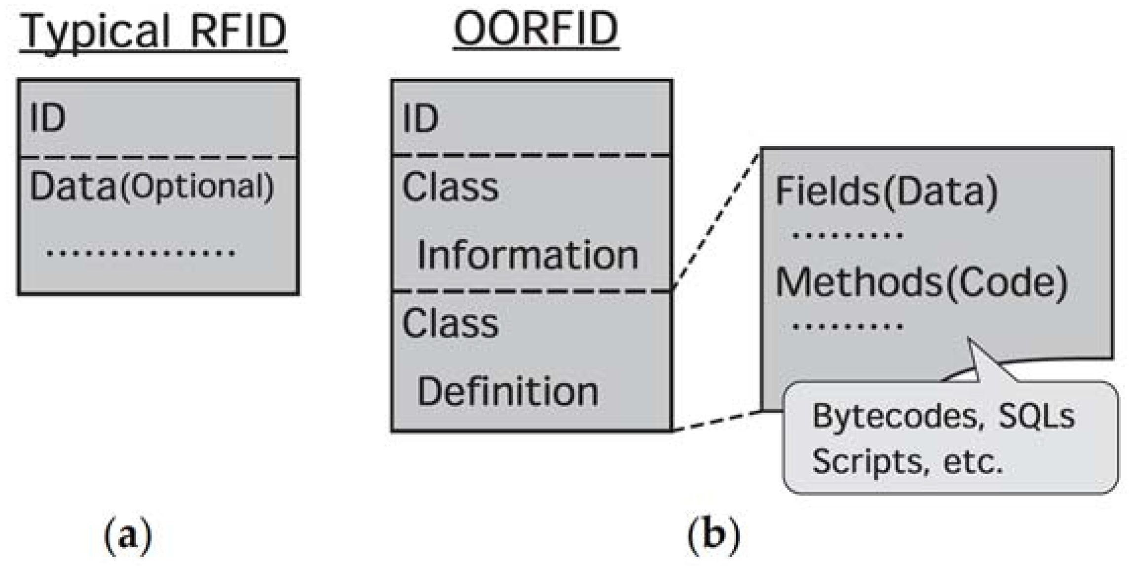
OORFID is the application of the idea of object orientation to an RFID tag. In the OORFID system, an OORFID tag is assumed as an object. Therefore, the three elements (ID, class information, and definition) are stored in one tag as shown on the right side of
Figure 4. The ID is the same as the ID in a typical RFID tag. Class information contains the class name to which the OORFID belongs. The class definition contains fields (object data) and methods (program code for processing data).
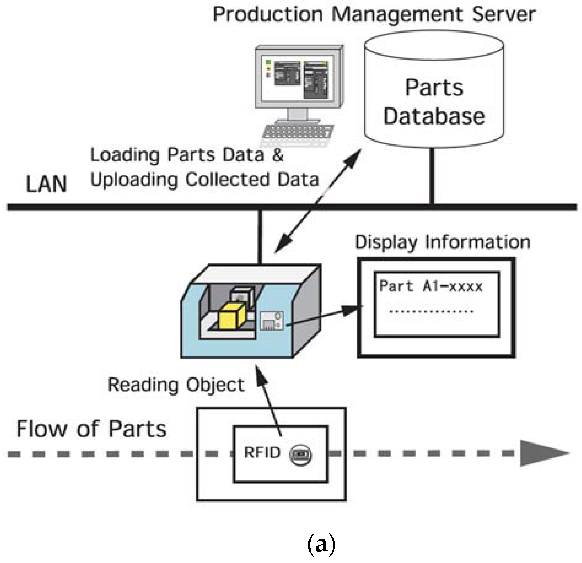
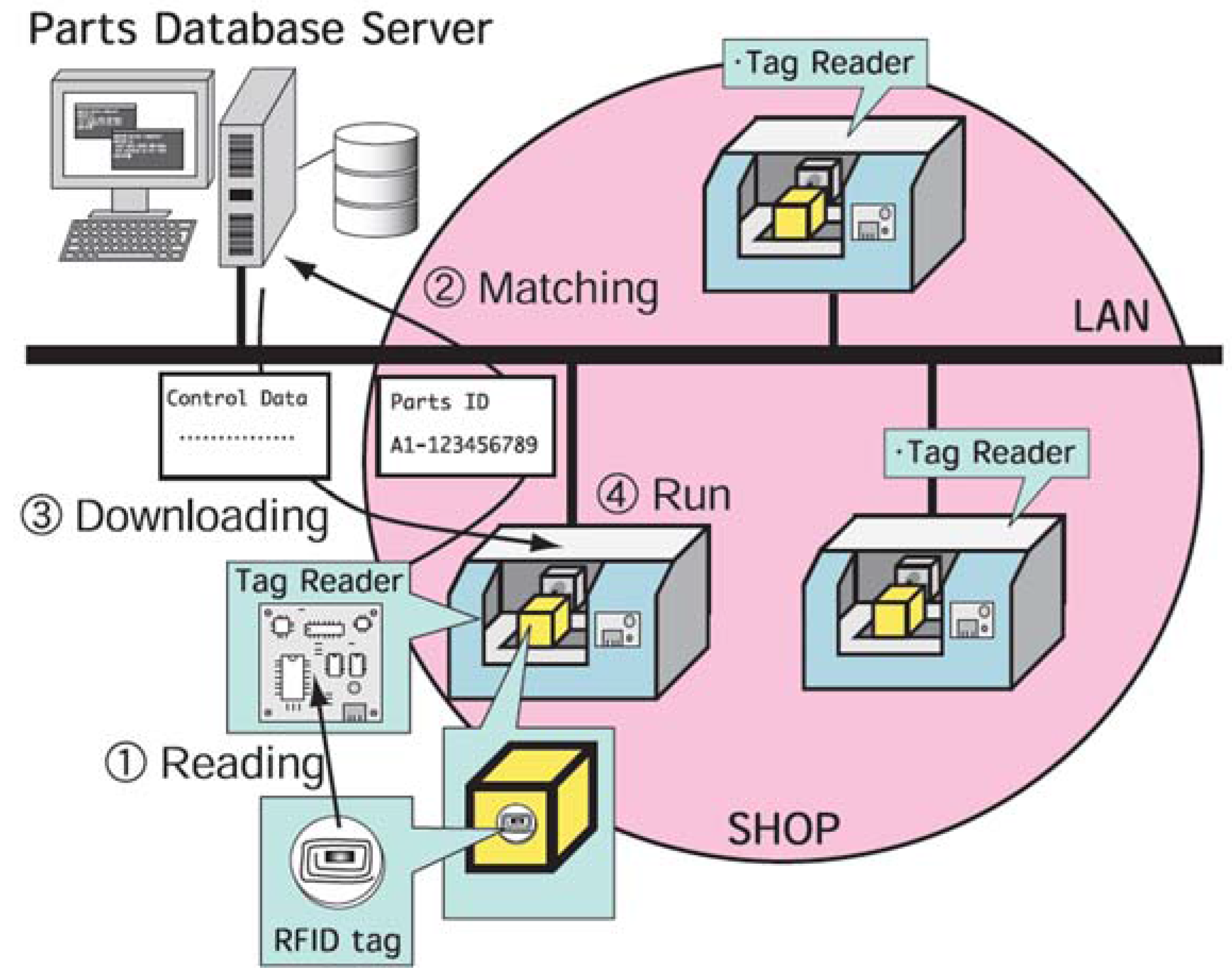
Typical RFIDs are used for the management of the products in the same way barcodes are. As shown in
Figure 5, an ID in a tag is read by tag readers and is used to access a database on a server computer. Then, the data that is read from the server is transferred through the network system to the machine that uses it [
11]. Therefore, the system size tends to be large because we must introduce the tags for each item: the tag readers, the database server computer system with network infrastructure, its software system, and so on.
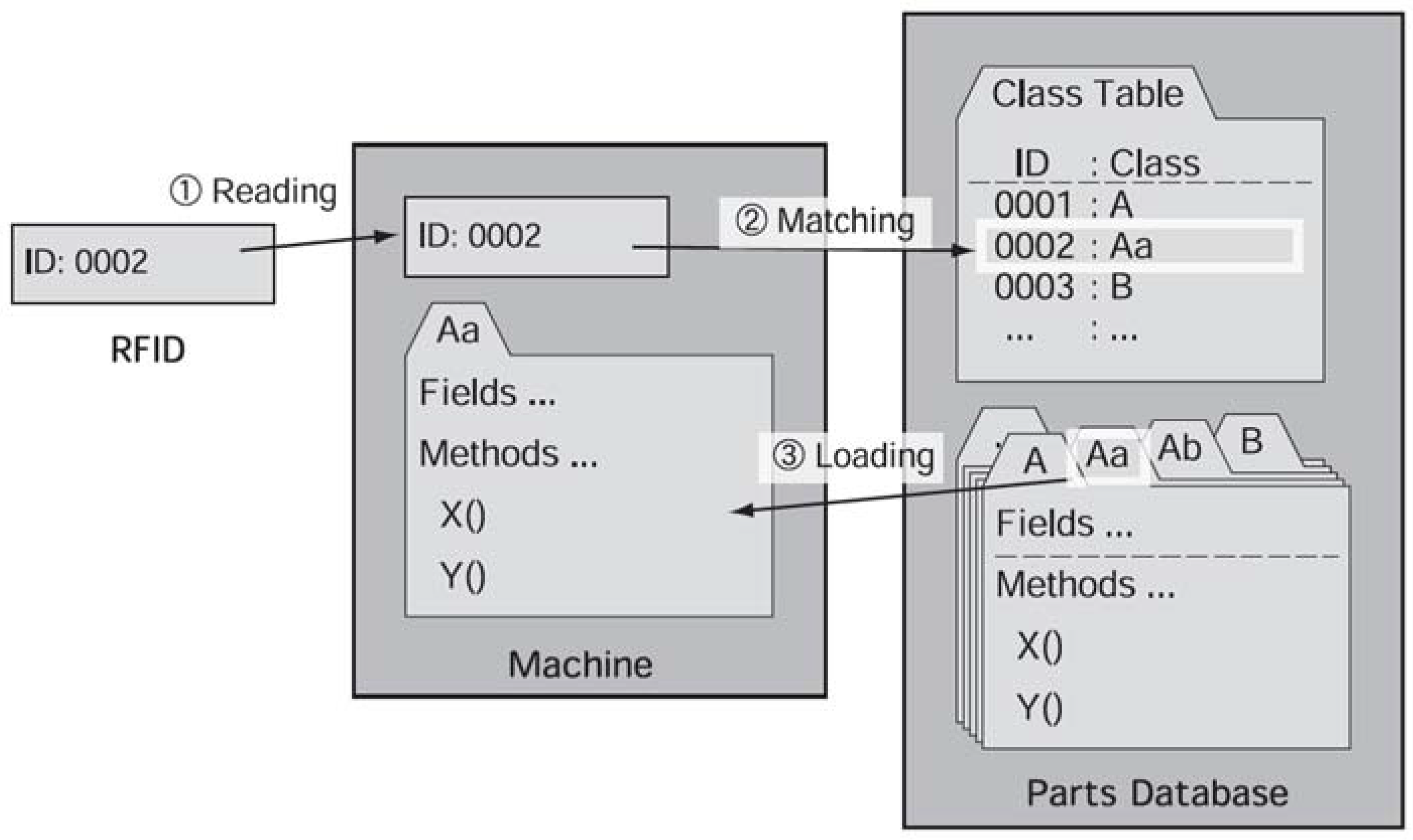
Figure 6 shows one informational flow using a typical RFID system. Firstly, a machine reads the ID of an RFID tag and checks the class table to get a class name matching with the ID. Next, using this class name, the machine accesses the parts database server and loads the related data from the server. Then, the machine executes processing with the data. In this kind of system, the parts database must consist of accurate data for all parts. If a change occurs in a part’s data, the database has to be modified even if this change is a very small one. In other words, whenever a modification of any part occurs, we must rebuild the parts database.
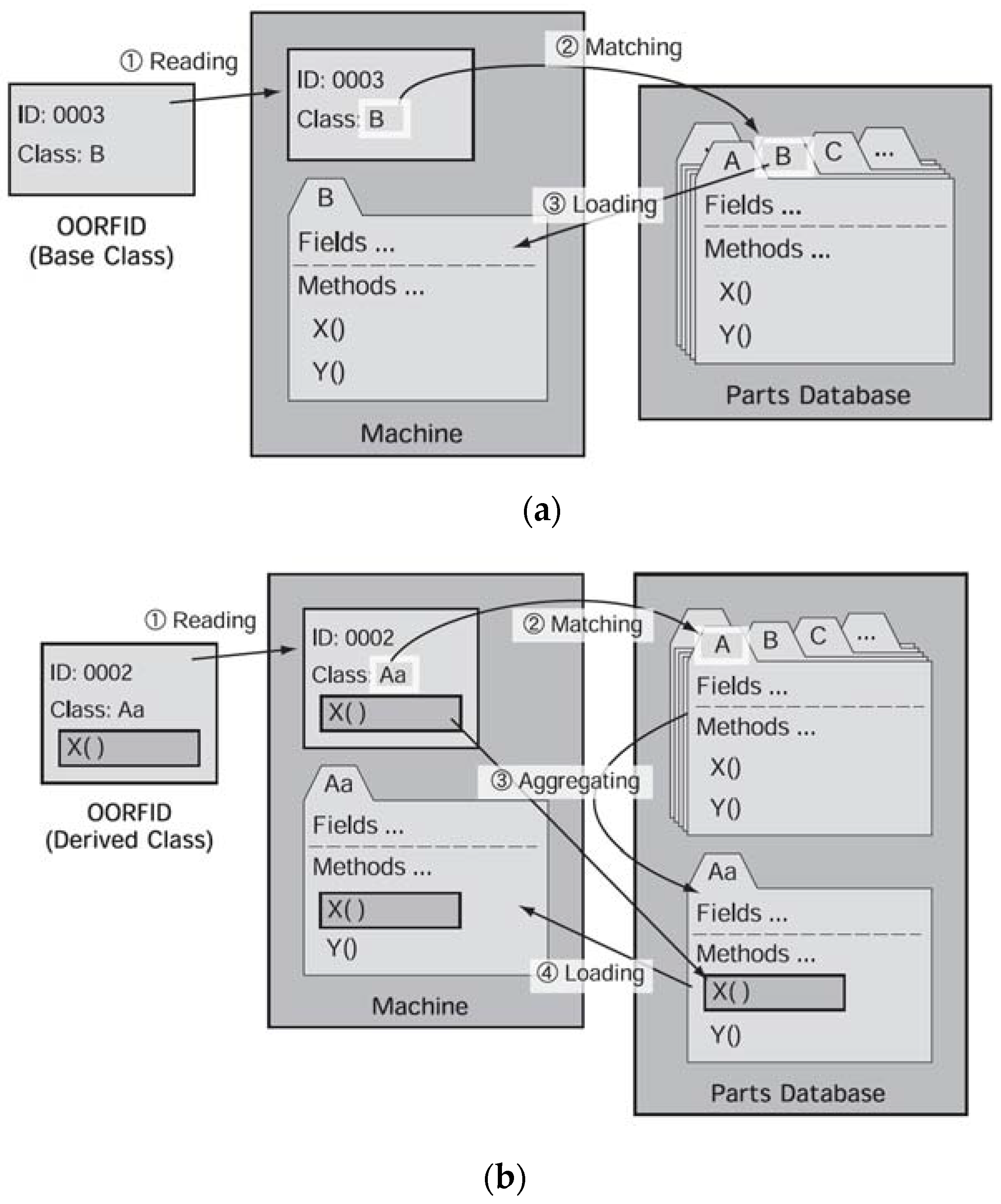
Figure 7 shows the informational flow using OORFID [
12]. Initially, the database contains the dataset of the parts belonging to the base class. This dataset is almost same as the above RFID system. If a part belongs to one of the base classes, the part data in the database is loaded by matching the class information in the OORFID tag with the class information stored in the database as shown in
Figure 7a. The information flow is also almost the same as a typical RFID system.
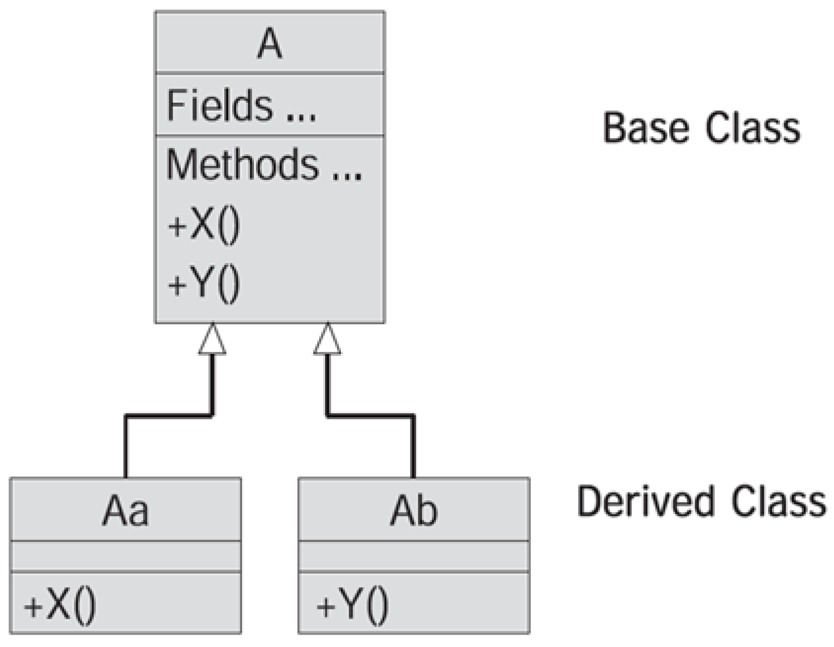
The OORFID system has an advantage when a modification occurs compared with typical RFID systems. Here, let us assume that there comes a new part that belongs to the class “Aa”. The difference between the class “A” and the class “Aa” is only the method “X( )”, i.e., the different attribute of these classes is the method “X( )”, and the other attributes are same as the class “A”.
Figure 8 shows the inherited relationship between the base class “A” and its derived class “Aa” in the UML class diagram. In a typical RFID system, it is necessary to update the database, even if a change is small as mentioned above. However in the OORFID system, we create the derived class OORFID that contains the updated method “X( )” as shown in
Figure 7b. The derived class OORFID is read and aggregated into the base class “A” that was read from the database, and the updated method “X( )” overrides the method “X( )” inherited from the base class “A”. At this point, we can use the new derived class “Aa” to control the machine. In addition, the database can be updated at a later date.
Using this mechanism, we can maintain the same interface (an RFID tag), and the different RFID tags bring the different behaviors. In this way, we realize polymorphism.
3. Conceptual Design
3.1. IoT with OORFID and Manufacturing Systems
The ICT systems such as the RFID system are established under the precondition that the system is completely constructed beforehand. For example, all of the production data is stored in the database and there is no modification of it, the infrastructure and the human resources are appropriately assigned, the identification of the parts is tied to the database properly, and so on. In such an environment, the OORFID system is not necessary because a typical RFID or barcode system operates properly to control the process.
However, in actual systems, especially those in the small-sized companies, it is difficult to construct a complete system for some of the following reasons:
lack of funds for appropriate technologies;
network is limited to a partial area;
production data is updated in real-time by upstream demands.
As a result, modifications of the database can occur. In such an environment, the OORFID system can be effective because a system modification is executed as a spot modification of the OORFID.
As mentioned before, the objective of this research is to suggest a design concept that combines the IoT and OORFID. In this system, the IoT technology is used for collecting, analyzing, and managing data; the OORFID system is used as a means to collect data and to control process in the manufacturing systems.
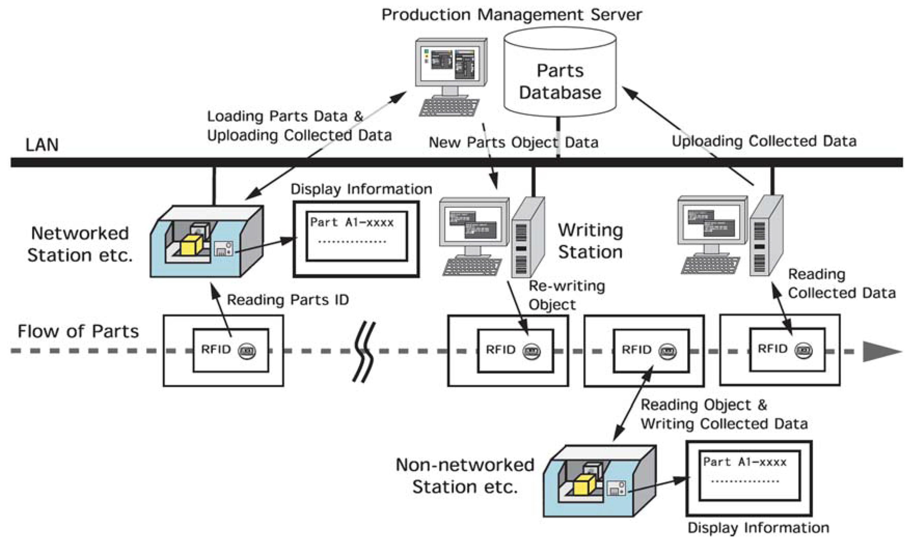
Figure 9 is an application of this concept. There is a networked area and non-networked area. In the networked area, all data for production is collected directly through the network. For the operation in the non-networked area, control data is stored in an OORFID as object by rewriting in the writing station before the part comes into the non-networked area. Data collection is executed in the non-networked area to rewrite and update the OORFID with collected data. The data in the OORFID is read in a networked area and transferred into the database. This usage is an application of an OORFID as a storage media.
3.2. Metamorphosis in OORFID System with IoT
Generally, in the software built by a general object-oriented language, once an object is instantiated in the computer memory, it is executed and then disappears from the memory at termination of the program. Therefore, the class has already been written in the software at the development stage and never metamorphoses into another object dynamically.
In the OORFID system, the OORFID tag is handled as an object in the same way as computer software; however, unlike computer software, it may be necessary to metamorphose an object to a derived object as a part moves through the manufacturing process. In a future IoT manufacturing system, if there will be an automation AI and the situation that the AI will decide that an object should be transformed to the derived OORIFD as the result of analysis, the metamorphosis concept of the OORFID will have meaning. This will actually be realized by rewriting the OORFID tag on demand.
4. Implementation
4.1. Experimental System
For the verification of the concept mentioned in the preceding chapter, an experimental IoT system was developed using OORFID. The following scenario is assumed:
The aim is to decrease failure rate of certain parts.
An RFID system has been previously introduced.
The failure is suspected to be related to temperature.
An IoT element is added to the system (a temperature sensor connected to the internet).
The temperature is observed through the practice of mieruka.
Following this scenario, the RFID-based manufacturing information system is redesigned to allow modification of the system using OORFID.
4.2. Application Design and Implementation
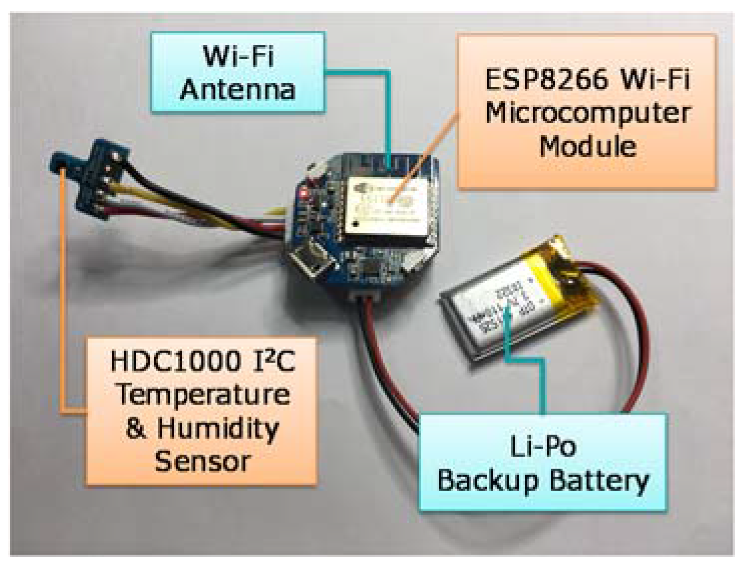
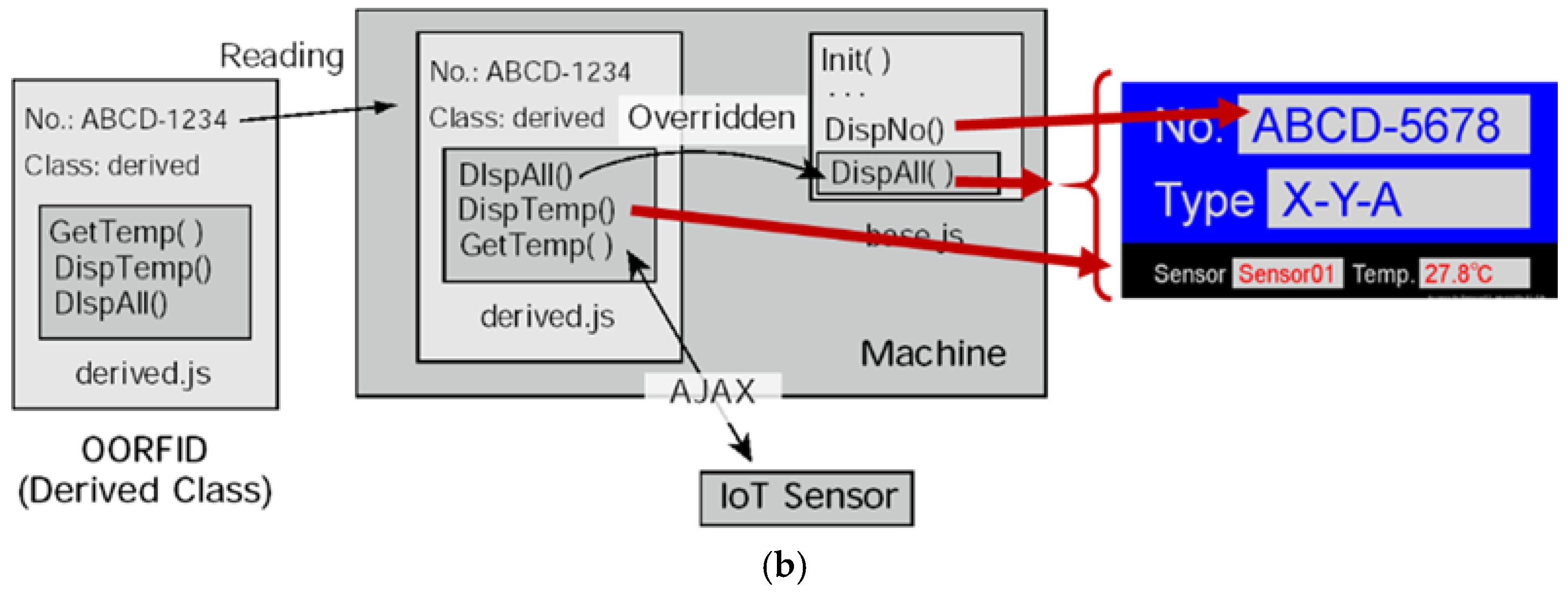
Using the assumed previously developed RFID system, it is replaced with the OORFID system. Firstly, a derived class OORFID has been designed from the base class that was normally used in the original system. The difference between the base class and the derived class is a method used for reading the temperature from the IoT sensor (
Figure 10) and displaying the measured value as shown in
Figure 11.
Next, the method must be coded. In this system, the method is written in JavaScript and HTML5. In the original system, the RFID tag has only the ID and the type of part. The methods of the base class (base.js: 1595 bytes in this case) are stored in the machine.
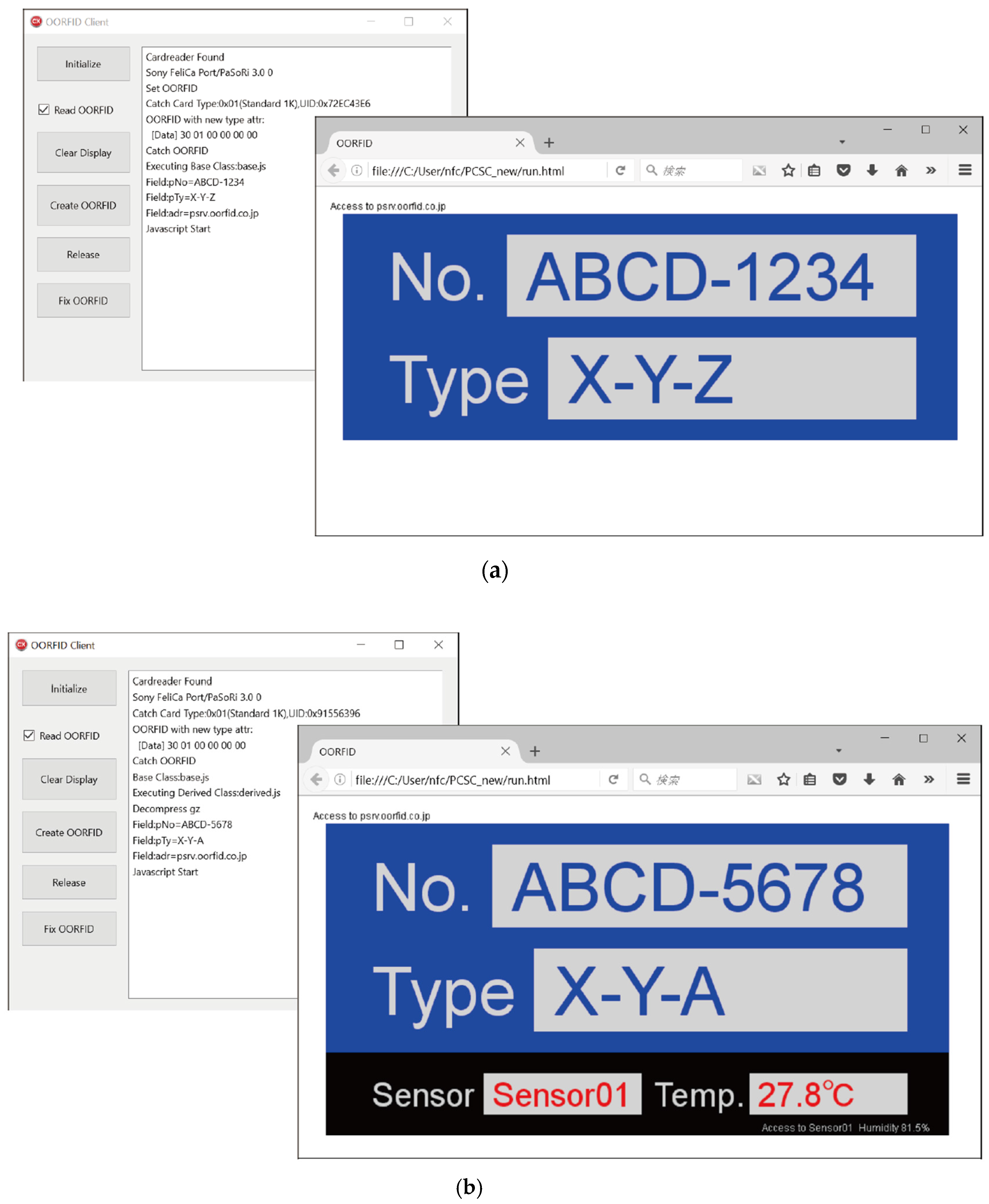
Figure 12a shows the execution of the original system. This window shows only the part number and type.
Figure 13a shows the informational flow of the system. The data stored in the base class OORFID (82 bytes) is simply displayed in the windows.
Figure 12b and
Figure 13b show the execution in case of the derived class OORFID (595 bytes). This OORFID contains the ID and the archived methods. Once these methods are read and unarchived to the derived class (derived.js: 935 bytes), the same-named methods in the base class are overridden by new methods in the derived OORFID, and these are executed on the web browser to communicate with the IoT temperature sensor and display the temperature of the part.
A PC (Windows 10, PC/SC library, PC/SC compatible RFID Reader/Writer) is used as the machine, an ESP8266 Wi-Fi microcomputer as the IoT sensor, and the MIFARE Classic 4 kB as the OORFID tag. The client program (OORFID reading/writing) and IoT sensor controller are written in C++, the OORFID objects are executed on the NW.js browser.
5. Discussion
The combination of the IoT and web technologies such as Java or HTML5 makes OORFID possible to execute on mobile devices such as smart phones or tablet computers for the management in manufacturing [
13]. This combination enables us to collect and display real-time information for manufacturing by reading OORFIDs with such wireless devices in hand.
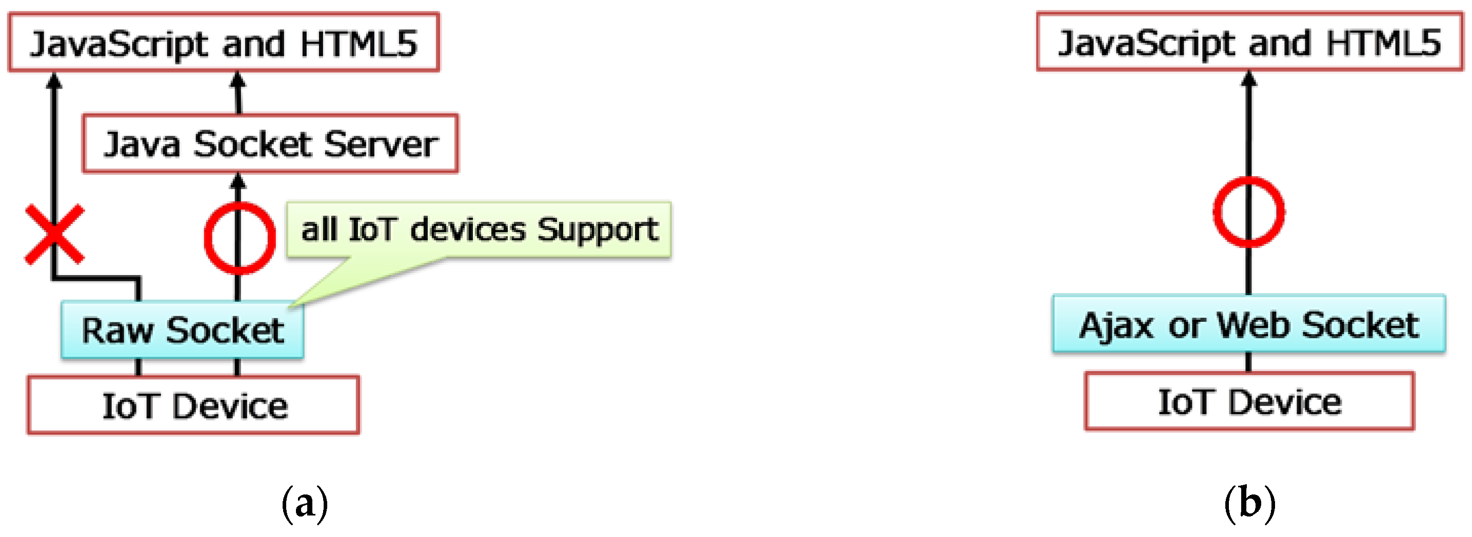
To interface with IoT devices, the HTML5 specification provides the WebSocket function. However, currently there are few IoT devices that support WebSocket. Since all IoT devices support a TCP/IP or UDP/IP raw socket control at least for the Internet connection, the initial implementation used the Java socket server to allow communication between the IoT device and the JavaScript and HTML5 programs as shown in
Figure 14a. The current implementation uses Ajax (Asynchronous JavaScript + XML) on the IoT device to communicate directly with the JavaScript program as show in
Figure 14b. This contributes a resource saving of the methods stored in the derived OORFID tag (e.g., A 1 k Mifare may be used in place of a 4 k Mifare).
In addition, in view of software development, writing methods in script program languages such as the JavaScript or HTML5, allows easy and rapid OORFID modification on site when a small change occurs without the need for production management server modification. Therefore, the combination of the IoT and OORFID also contributes to mobility and flexibility.
6. Conclusions
In this research, a conceptual design that introduces OORFID to a manufacturing information system connected to the IoT was described. In this design concept combining the IoT and OORFID, the IoT technology is used for collecting, analyzing, and managing data; and the OORFID system is used for process control to improve the flexibility in the manufacturing systems.
For the verification of this design concept, an experimental RFID-based manufacturing information system with an IoT element was redesigned. As a proof of concept, a scenario was assumed where mieruka is conducted to observe measurement values obtained from an IoT sensor. Following this scenario, the RFID-based manufacturing information system was redesigned to modify the system using a derived OORFID. As a result, it was shown that the OORFID controls the manufacturing information system, in particular the communication with the IoT sensor, and the combination of the IoT and OORFID contributes to mobility and flexibility in software development for the manufacturing information system.

