Experimental Characterization of a Dual-Polarised Parasitic Patch Antenna


DIEI and ELEDIA@UNICAS—University of Cassino and S.L., via G. Di Biasio 43, 03043 Cassino, Italy
*
Author to whom correspondence should be addressed.
Electronics 2017, 6(4), 108; https://doi.org/10.3390/electronics6040108
Submission received: 17 October 2017
/
Revised: 7 December 2017
/
Accepted: 11 December 2017
/
Published: 14 December 2017
(This article belongs to the Special Issue Reconfigurable Antennas)
Abstract
:The aim of this paper is to present the experimental characterization of a reconfigurable parasitic patch antenna for Multiple Input Multiple Output (MIMO) applications. The proposed antenna is able to work with two different polarizations, providing separate control of the antenna pattern of each of the two polarizations. Both numerical and experimental results show the adaptive capabilities of the antenna, proving its effectiveness for MIMO applications.
1. Introduction
Multiple Input Multiple Output (MIMO) systems have received great attention during past decades due to their performance improvement with respect to Single Input Single Output (SISO) wireless communication systems [1,2,3,4,5,6]; such an improvement is mainly due to the capability to spatially multiplex the information over multiple space-time channels. A number of antenna architectures, exploiting reconfigurability features [7,8], especially designed for a MIMO approach, has been presented [9,10,11,12,13]. An interesting review of the emerging techniques for printed reconfigurable antennas can be found in [14]. Such antennas are able to adapt their radiating characteristics to the particular realization of the electromagnetic environment in which they are working, thus achieving better performances. In particular, the architecture presented in [9] uses a high number of Micro Electro-Mechanical Systems (MEMS) switches in order to change the radiating characteristics, i.e., the polarization, of each element of the array; the solution presented in [10], instead, is based on a number of parasitic elements surrounding the active ones, connected to electronically controllable impedances. The latter solution can provide an interesting performance improvement but is not as easily embeddable as the former in small size communication systems (like laptops) due to its size. Moreover, it is not suitable for exploiting dual-polarization capability. As a matter of fact, it has been shown [15] that polarization diversity in conjunction with spatial multiplexing allows a better symbol error rate. In [16] a two-port, low-profile, adaptive, parasitic antenna based on a similar operation principle as in [10], but was investigated in planar technology. In addition, the presented antenna provides two radiative modes with orthogonal polarization. The aim of this paper is the experimental characterization of the antenna, to prove its effectiveness for MIMO applications. As shown later on, the agreement between measurements and simulations is excellent. In Section 2, some details on the architecture presented in [16] are summarized, whereas in Section 3, the most relevant numerical results are recalled. Section 4 is devoted to measurements.
2. The Antenna Architecture
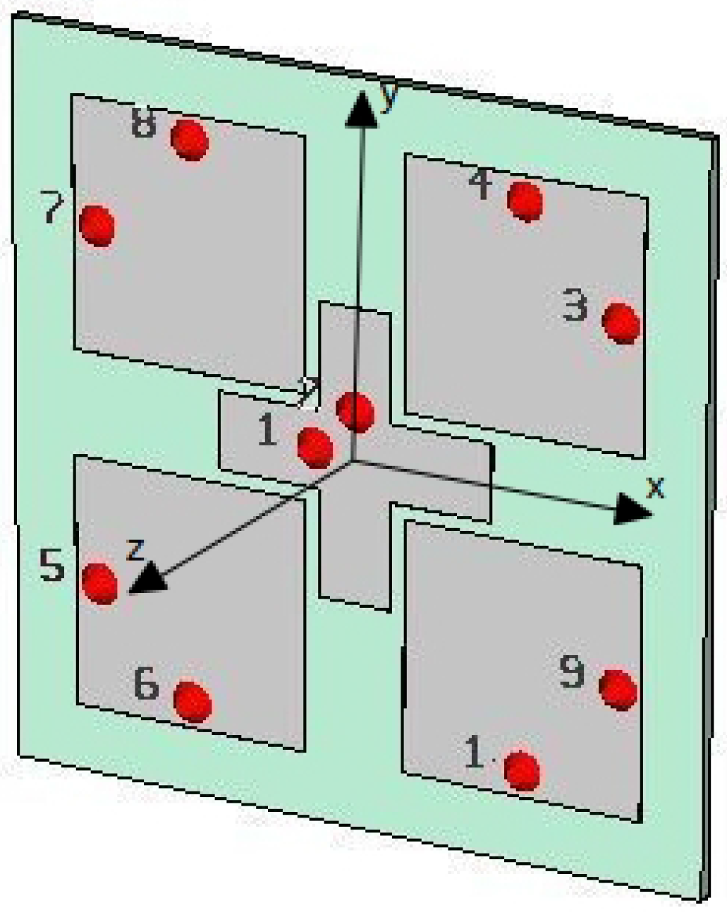
The layout of the proposed antenna is sketched in Figure 1 and a picture of the manufactured antenna is shown in Figure 2. The active element is cross shaped; such a choice allows to achieve dual polarization by means of two feedpoints (labelled 1 and 2 in Figure 1). A proper choice of the positions of the feedpoints on the cross patch allows to excite currents in orthogonal directions, thus having a very low cross-talk among the ports.
The four square patches surrounding the active element have been designed so as to resonate at 2.4 GHz, and their distance from the cross patch has been optimized to maximize the coupling with it. Due to their square shape, such patches exhibit two degenerate and orthogonal resonating modes, which can couple to any of the working polarizations of the active element. The dimensions of the antenna layout are summarized in Table 1.
The basic working principle of the overall antenna is the following. The square patches could be put in or out of resonance by means of simple diode-based switches, which, in simulations, have been modelled as shorting pins, labelled from 3 to 10 in Figure 1.
In the “ON” state, the switch provides a very high impedance level, thus allowing the patch resonance (in simulations no shorting pin is present). In the “OFF” state, the switch provides a very low impedance level, thus preventing the patch resonance (in simulations the shorting pin is present). Consequently, there can be an induced radiating current on the patches, depending on the switch state, contributing to the overall radiation diagram of the antenna. Depending on how many, and which, switches are in the “ON” state, it is possible to get different radiation diagrams. Such a behaviour can be perfectly replicated for each polarization, due to the symmetry of the antenna.
The antenna with the dimensions summarized in Table 1 has been manufactured on an FR4 substrate, with thickness of 1.524 mm, and fed by means of a standard 50 coaxial cable. Since the aim of this paper is to prove the feasibility of the proposed antenna architecture and the agreement with simulations, in the prototype, the switches have been replaced by shorting pins and open circuits (i.e., no shorting pin).
3. Numerical and Experimental Results
In this Section, some numerical and experimental results are shown. All the simulations have been performed by means of Computer Simulation Technology (CST) Microwave Studio full-wave simulation software (CST-MWS 2014, CST GmbH, Darmstadt, Germany, 2014), with a mesh of 20 lines per wavelength. The measurements have been performed in the anechoic chamber of the University of Cassino and Southern Lazio, by means of a vector network analyser Anritsu 37347C (Anritsu Corporation, Kanagawa, Japan) with Anritsu calibration kit 3650.
As an example, the simulated induced current when the upper right patch is put out of resonance is shown in Figure 3. As can be seen, no induced current is present on the shortened patch, thus producing an inclination of the main lobe with respect to broadside direction (27 degrees in this case).
More numerical results can be found in [16].
Depending on the switches configuration, a total of 15 different working conditions can be achieved. In the following such configurations will be indicated as “antenna ” and some results and comparisons with simulations are shown.
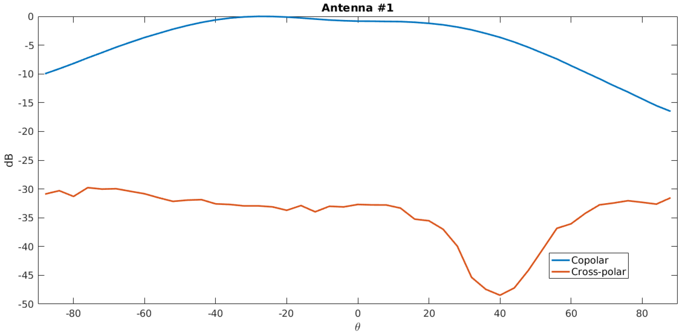
As a first task, the cross polarization when all the patches are in the “ON” state is presented in Figure 4 (antenna ). As can be seen, the measured cross-polarization level is about 30 dB below the co-polar component, thus confirming that the two polarizations orthogonal and can be used independently. This is also confirmed by the plot of isolation between ports 1 and 2 (Figure 5).
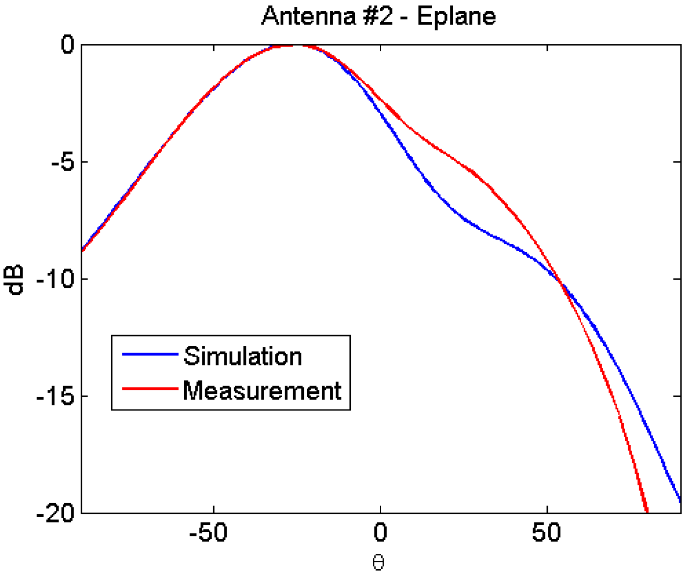
In Figure 6 and Figure 7 the radiation diagram of the antenna in configuration , namely with the upper right patch “OFF”, are shown in E and H planes respectively ( and planes respectively). As can be seen, the agreement between simulations and measurements is excellent.
When the upper right patch is turned “ON” and the upper left patch is turned “OFF” (configuration ) a switch of the radiation diagram in the E plane is to be expected. Such a behaviour is confirmed in Figure 8 while the H plane is shown in Figure 9. Again, the agreement between measurement and simulations is excellent.
In all the tested configurations a very good agreement was obtained, but the results are not shown here.
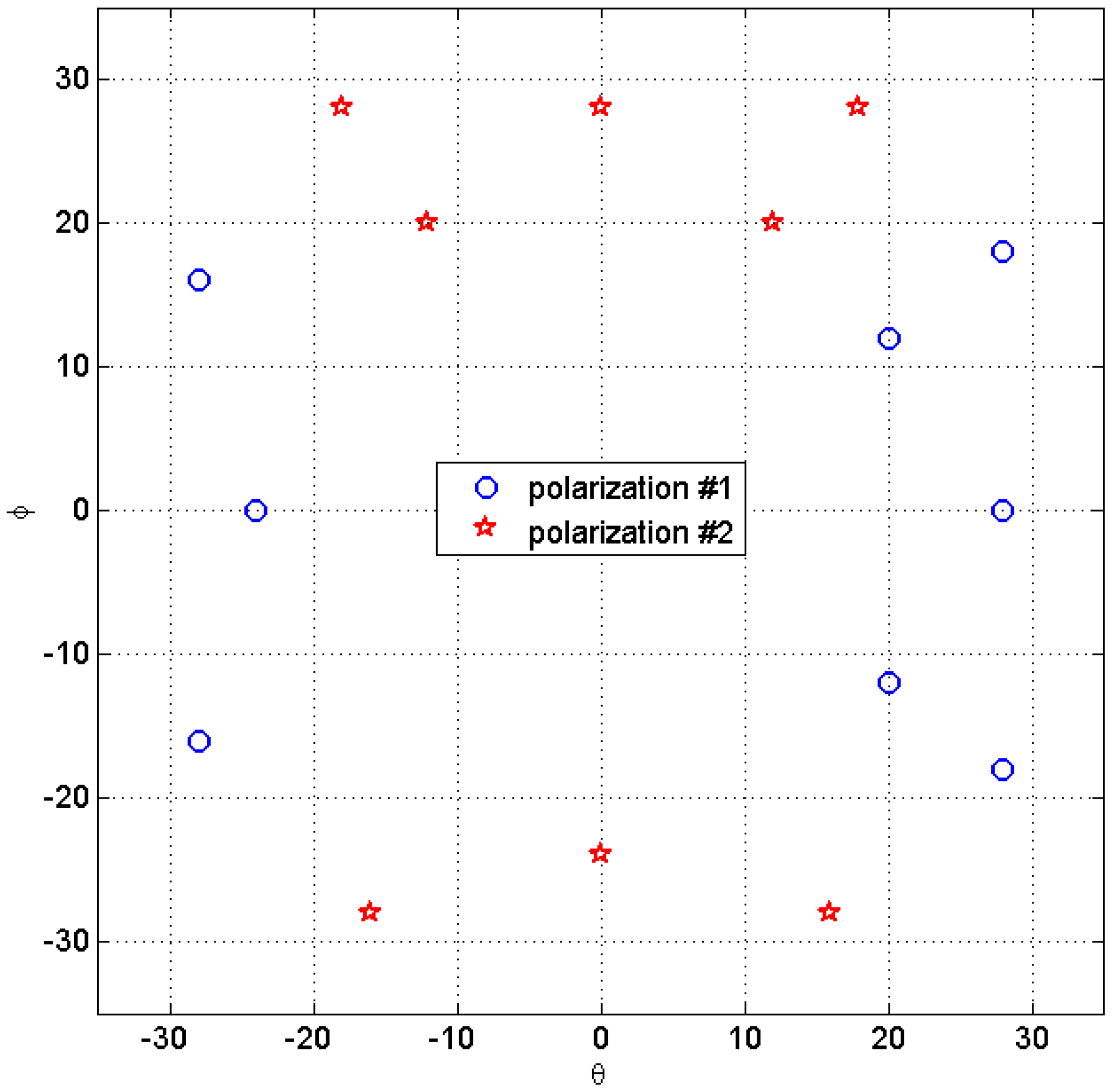
The reconfigurability properties of the proposed antenna are summarized in Figure 10. As can be seen, exploiting both polarizations the antenna can switch basically in all directions around broadside direction, thus confirming its effectiveness as a reconfigurable antenna for MIMO applications.
4. Conclusions
In the present work the experimental characterization of an adaptive parasitic patch antenna for MIMO systems has been presented. The antenna was presented in a previous work by the authors, and has been finally manufactured and tested. In the feasibility study based on simulations, the possibility to achieve, in planar technology, the reconfigurability features of the antenna analysed in [10] had been conjectured. In the present work, the performances and the effectiveness of the antenna have been experimentally confirmed and validated. The antenna has the capability to modify its radiation pattern in both polarizations, depending on the switches configuration.
Author Contributions
D.P. conceived and designed the antenna, F.S. performed the simulations; M.D.M., D.P. and F.S. conceived and designed the experiments; G.P. and M.L. helped with the discussion and comparison of the results; D.P. and F.S. wrote the paper.
Conflicts of Interest
The authors declare no conflict of interest.
References
- Paulraj, A.; Nabar, R.; Gore, D. Introduction to Space-Time Wireless Communications; Cambridge University Press: Cambridge, UK, 2003. [Google Scholar]
- Migliore, M.D. On the role of the number of degrees of freedom of the field in MIMO channels. IEEE Trans. Antennas Propag. 2006, 54, 620–628. [Google Scholar] [CrossRef]
- Migliore, M.D.; Pinchera, D.; Massa, A.; Azaro, R.; Schettino, F.; Lizzi, L. An investigation on UWB-MIMO communication systems based on an experimental channel characterization. IEEE Trans. Antennas Propag. 2008, 56, 3081–3083. [Google Scholar] [CrossRef]
- Martini, A.; Massa, A.; Franceschetti, M. Physical limits to the capacity of wide-band Gaussian MIMO channels. IEEE Trans. Wirel. Commun. 2009, 8. [Google Scholar] [CrossRef]
- Pinchera, D. On the limits of MIMO systems: Complete matrix model and intuitive graphic representation. In Proceedings of the 5th European Conference on Antennas and Propagation (EUCAP), Rome, Italy, 11–15 April 2011; IEEE: Piscataway, NJ, USA, 2011; pp. 1248–1252. [Google Scholar]
- Oliveri, G.; Caramanica, F.; Migliore, M.; Massa, A. Synthesis of nonuniform MIMO arrays through combinatorial sets. IEEE Antennas Wirel. Propag. Lett. 2012, 11, 728–731. [Google Scholar] [CrossRef]
- Migliore, M.D.; Pinchera, D.; Schettino, F. A simple and robust adaptive parasitic antenna. IEEE Trans. Antennas Propag. 2005, 53, 3262–3272. [Google Scholar] [CrossRef]
- Donelli, M.; Azaro, R.; Fimognari, L.; Massa, A. A planar electronically reconfigurable Wi-Fi band antenna based on a parasitic microstrip structure. IEEE Antennas Wirel. Propag. Lett. 2007, 6, 623–626. [Google Scholar] [CrossRef]
- Cetiner, B.A.; Akay, E.; Sengul, E.; Ayanoglu, E. A MIMO system with multifunctional reconfigurable antennas. IEEE Antennas Wirel. Propag. Lett. 2006, 5, 463–466. [Google Scholar] [CrossRef]
- Migliore, M.D.; Pinchera, D.; Schettino, F. Improving channel capacity using adaptive MIMO antennas. IEEE Trans. Antennas Propag. 2006, 54, 3481–3489. [Google Scholar] [CrossRef]
- Piazza, D.; Kirsch, N.J.; Forenza, A.; Heath, R.W.; Dandekar, K.R. Design and evaluation of a reconfigurable antenna array for MIMO systems. IEEE Trans. Antennas Propag. 2008, 56, 869–881. [Google Scholar] [CrossRef]
- Pinchera, D.; Wallace, J.W.; Migliore, M.D.; Jensen, M.A. Experimental analysis of a wideband adaptive-MIMO antenna. IEEE Trans. Antennas Propag. 2008, 56, 908–913. [Google Scholar] [CrossRef]
- Boerman, J.D.; Bernhard, J.T. Performance study of pattern reconfigurable antennas in MIMO communication systems. IEEE Trans. Antennas Propag. 2008, 56, 231–236. [Google Scholar] [CrossRef]
- Kholapure, A.S.; Karandikar, R. Emerging techniques for printed reconfigurable antenna: A review. In Proceedings of the 2016 Second International Conference on Research in Computational Intelligence and Communication Networks (ICRCICN), Kolkata, India, 23–25 September 2016; IEEE: Piscataway, NJ, USA, 2016; pp. 57–61. [Google Scholar]
- Nabar, R.U.; Bolcskei, H.; Erceg, V.; Gesbert, D.; Paulraj, A.J. Performance of multiantenna signaling techniques] in the presence of polarization diversity. IEEE Trans. Signal Process. 2002, 50, 2553–2562. [Google Scholar] [CrossRef]
- Pinchera, D.; Schettino, F. A dual-polarized parasitic patch antenna for MIMO systems. In Proceedings of the 2009 European Microwave Conference (EuMC), Rome, Italy, 29 September–1 October 2009; IEEE: Piscataway, NJ, USA, 2009; pp. 642–644. [Google Scholar]
Figure 1.
Antenna layout simulated by means of Computer Simulation Technology (CST) Microwave Studio.
Figure 1.
Antenna layout simulated by means of Computer Simulation Technology (CST) Microwave Studio.

Figure 2.
Photo of one of the realized antennas.
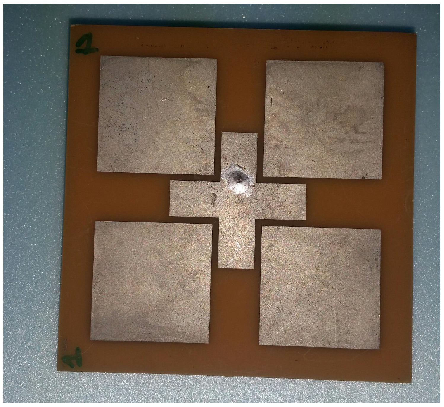
Figure 3.
Current behaviour when the antenna is fed by port 1, and the upper right patch is out of resonance.
Figure 3.
Current behaviour when the antenna is fed by port 1, and the upper right patch is out of resonance.
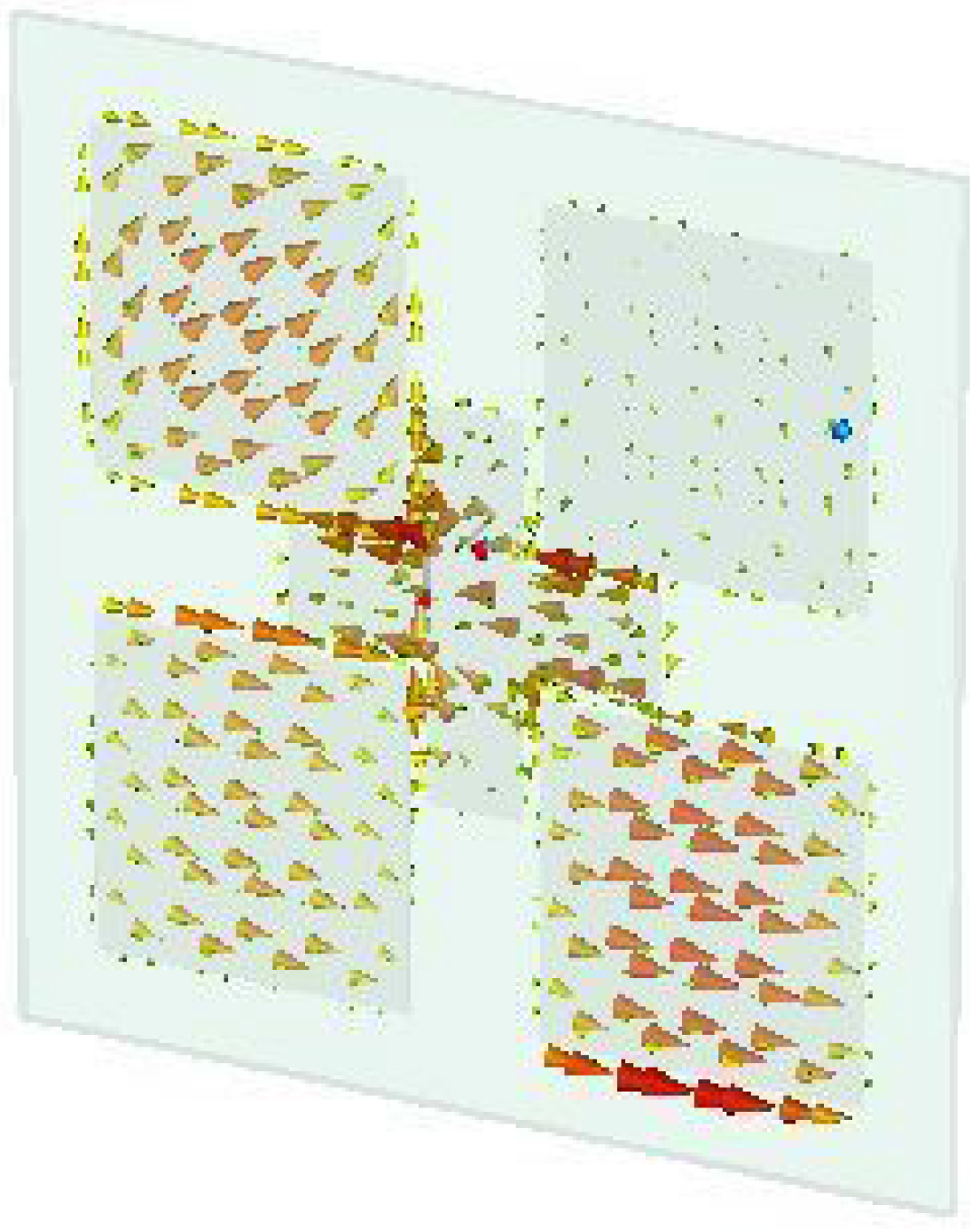
Figure 4.
Measured cross polarization when all the patches are in the “ON” state.

Figure 5.
Isolation between port 1 and 2 for some antenna configurations.

Figure 6.
Comparison between measurements and simulations for antenna configuration (upper right patch “OFF”)—E plane.
Figure 6.
Comparison between measurements and simulations for antenna configuration (upper right patch “OFF”)—E plane.

Figure 7.
Comparison between measurements and simulations for antenna configuration (upper right patch “OFF”)—H plane.
Figure 7.
Comparison between measurements and simulations for antenna configuration (upper right patch “OFF”)—H plane.
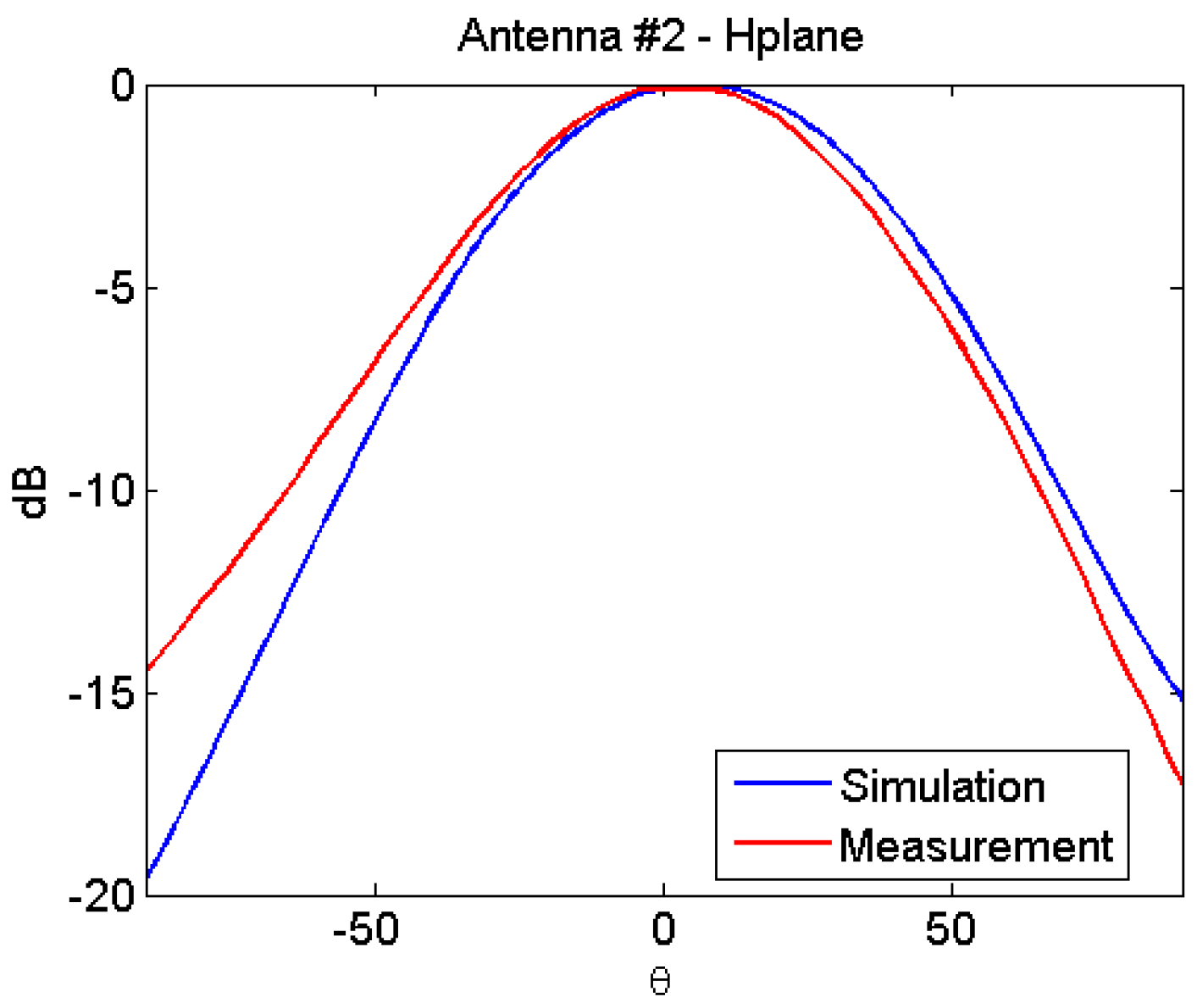
Figure 8.
Comparison between measurements and simulations for antenna configuration (upper left patch “OFF”)—E plane.
Figure 8.
Comparison between measurements and simulations for antenna configuration (upper left patch “OFF”)—E plane.

Figure 9.
Comparison between measurements and simulations for antenna configuration (upper left patch “OFF”)—H plane.
Figure 9.
Comparison between measurements and simulations for antenna configuration (upper left patch “OFF”)—H plane.
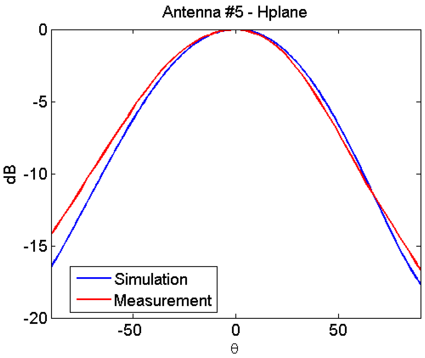
Figure 10.
Main lobe directions achievable by means of the proposed antenna, in both polarizations.

Table 1.
Geometry dimensions.
| Cross arm length | 28.8 mm |
| Cross arm width | 8.39 mm |
| Resonant patch side | 27.2 mm |
| Patch-cross distance | 1.5 mm |
| Off-center feeding ports distance | 4.7 mm |
© 2017 by the authors. Licensee MDPI, Basel, Switzerland. This article is an open access article distributed under the terms and conditions of the Creative Commons Attribution (CC BY) license (http://creativecommons.org/licenses/by/4.0/).
Share and Cite
MDPI and ACS Style
Pinchera, D.; Lucido, M.; Migliore, M.D.; Schettino, F.; Panariello, G. Experimental Characterization of a Dual-Polarised Parasitic Patch Antenna. Electronics 2017, 6, 108. https://doi.org/10.3390/electronics6040108
AMA Style
Pinchera D, Lucido M, Migliore MD, Schettino F, Panariello G. Experimental Characterization of a Dual-Polarised Parasitic Patch Antenna. Electronics. 2017; 6(4):108. https://doi.org/10.3390/electronics6040108
Chicago/Turabian StylePinchera, Daniele, Mario Lucido, Marco Donald Migliore, Fulvio Schettino, and Gaetano Panariello. 2017. "Experimental Characterization of a Dual-Polarised Parasitic Patch Antenna" Electronics 6, no. 4: 108. https://doi.org/10.3390/electronics6040108
Note that from the first issue of 2016, this journal uses article numbers instead of page numbers. See further details here.