Quiet Zone Enhancement for a Target Location Using an Improved Virtual Sensing Algorithm

Department of Electrical, Electronics and Communication Engineering, Korea University of Technology and Education, Cheonan, Chungnam 330-708, Korea
*
Author to whom correspondence should be addressed.
Electronics 2017, 6(4), 76; https://doi.org/10.3390/electronics6040076
Submission received: 22 August 2017
/
Revised: 15 September 2017
/
Accepted: 28 September 2017
/
Published: 3 October 2017
Abstract
:Generating a quiet zone at a target location is the ultimate goal of active noise control (ANC). Generally, the best noise cancellation is achieved at the locations of error sensors. However, the distribution of physical error sensors at a given location is not always convenient or feasible. To overcome this challenge, a number of virtual sensing algorithms for ANC have been researched. Using the physical error signals and knowledge of the system, the adaptive least mean square (LMS) virtual sensing algorithm estimates the error signal at a location that is remote from the physical error sensor, referred to as the virtual location. It achieves excellent performance under the assumption that the unknown primary path is fixed, but its performance decreases significantly if the path is constantly changing. This paper presents a real-time ANC system with an improved virtual sensing algorithm to solve this problem. The proposed system was tested to enhance the quiet zone in a constantly changing environment; an enhanced quiet zone was created, and the noise cancellation, especially at the target location, obviously improved.
1. Introduction
Active noise control (ANC) cancels primary noise by generating and combining anti-noise (with equal amplitude but opposite phase) at the location of the error microphone. It efficiently attenuates low-frequency noise with benefits in size and cost [1]. Generating a quiet zone, in which the noise is canceled, is the main purpose. A quiet zone with sufficient size and good noise attenuation is considerably significant. Here, a multichannel real-time ANC system was designed to achieve this this goal. The multichannel ANC employs one reference microphone, two canceling speakers, and four physical error microphones. A floating-point digital signal processor, TMS320C6713, was used to conduct the real-time experiments.
Generally, the best noise cancellation of a quiet zone is achieved at the locations of error sensors, and the distribution of physical error sensors should be close to the target location [2,3,4,5]. However, this might not always be a feasible solution. To enable a microphone as an error sensor to be located away from the target position, several virtual sensing algorithms for ANC have been researched [6,7,8,9,10,11,12,13,14,15,16,17,18,19,20,21]. The adaptive LMS virtual sensing algorithm estimates the error signal by placing a number of physical microphones in space and another physical microphone at the desired location temporarily. It is possible to adapt the gains of the sensing microphones so that the weighted sum of these signals produces the same signal as that of the desired microphone output [6]. Once convergence has been achieved, the weights may be fixed and the roaming microphone is removed, which results in an optimal virtual microphone. The idea of the adaptive LMS virtual sensing is very attractive for some applications; however, if the unknown primary path is constantly varying, the adaptive LMS virtual sensing algorithm cannot maintain excellent performance. This paper presents a modified adaptive LMS algorithm to solve this problem. The proposed algorithm achieves the microphone weights on the basis of the secondary paths, the secondary paths are fixed during the system operation. Thus, the proposed algorithm effectively eliminates the influence of a constantly changing primary path. A multichannel ANC with an improved virtual sensing algorithm was then designed to enhance the noise cancellation at the target location.
The organization of this paper is as follows: Section 2 presents the design of real-time multichannel ANC system. In Section 3, the adaptive LMS virtual sensing algorithm is introduced and the improved adaptive LMS virtual sensing algorithm is proposed. Experimental results are presented in Section 4, and the conclusions are summarized in Section 5.
2. Multichannel Real-Time ANC System
The filtered-x least mean square (FXLMS) algorithm has been widely used in practical ANC due to its robustness and simplicity. In our proposed system, the multichannel delay-compensated FXLMS algorithm is applied [22], it achieves a faster convergence rate and better performance with only double computation load, and this guarantees the possibility of real-time implementation. The multichannel delay-compensated FXLMS is illustrated in Figure 1. It employs reference sensors to form the reference signal vector, generates canceling signals to drive the corresponding secondary sources, and distributes error sensors over desired locations to measure the residual noise components.
The wide arrows represent an array of signals that are symbolically expressed as vectors. The matrix represents primary path transfer functions, , from the reference signal to each error signal . The matrix represents secondary-path transfer functions, , from secondary sources to error sensors. There are possible feedforward channels, each demanding a separate adaptive filter , and these adaptive filters are represented by the matrix . The multichannel delay-compensated FXLMS algorithm uses the estimated plant models to subtract the contribution of the secondary path from the error signals so that the estimated primary field signals are obtained. The adaptive filters then try to predict the estimated signals instead of the original signals.
Using the following additional notations, we obtained the multichannel delay-compensated FXLMS algorithm described by Equations (1)–(5), where are the coefficients of the order FIR filter , are the coefficients of the order FIR filter , controls the step size of adaptive filter, is the cancelling noise signal, is the filtered reference signal, is the estimation of the primary sound field at the error sensor, and is the alternative error signal.
where and .
where and .
where .
where .
Appling the delay-compensated FXLMS, a real-time ANC system was designed. It employs a 1 × 2 × 4 multi-channel structure as shown in Figure 2.
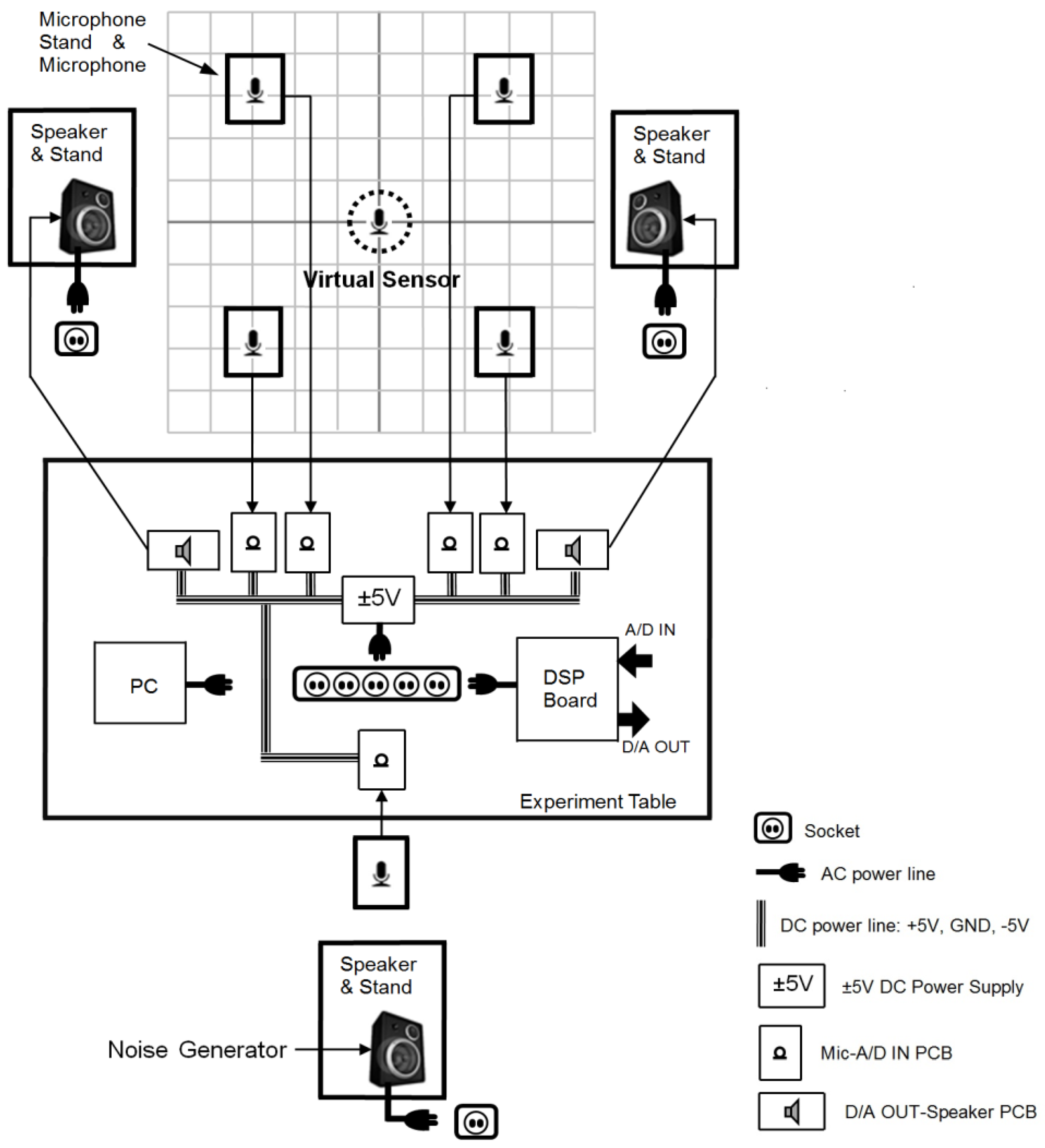
The primary noise was generated by a function generator and output from a powered studio monitor speaker—YAMAHA HS50. The reference microphone and error microphones were unidirectional condenser microphones with a 46 ± 4 dB sensitivity and a 70 Hz ~ 20 kHz frequency response range. The canceling loudspeakers had the same specifications as the primary loudspeaker.
The system was implemented in the TMS320C6713 digital signal processor kit; the kit employs 12-bit 8-channel A/D convertor AD7888 and 12-bit 4-channel D/A convertor AD7564. Both the analog input voltage of A/D convertor and analog output voltage of D/A convertor were 0 ~ 2.5 V, so the +1.25 V bias voltage before the ADC signal input and the −1.25 V bias voltage after the DAC signal output were necessary. The anti-aliasing filter and reconstruction filter were 4th-order low-pass Butterworth filters. Their passband frequency was 750 Hz, and the stopband frequency was set to 1000 Hz with −9 dB stopband attenuation. For the operational amplifier, a balanced input microphone amplifier circuit with adjustable gain was designed using a high-fidelity audio operational amplifier IC LME 49740.
Our system was implemented in a 15 m × 10 m × 3 m room; the height of the microphones and speakers, with their stands, was adjusted to 1.5 m.
3. Virtual Sensing Algorithm
3.1. Adaptive LMS Virtual Sensing Algorithm for ANC
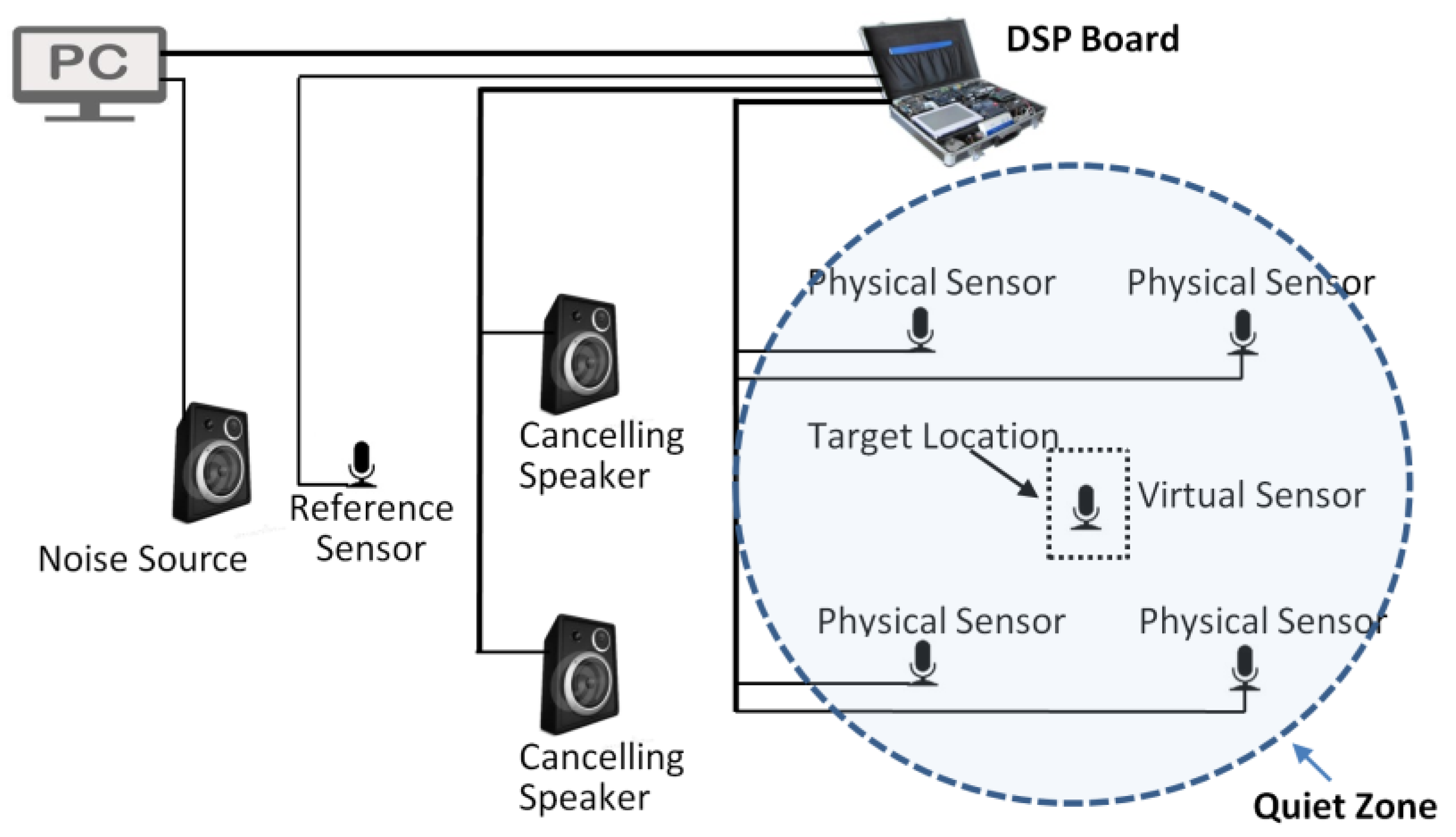
ANC with virtual sensors has been researched to generate quiet zones at locations where the arrangement of physical microphones is inconvenient. The virtual sensing algorithm estimates the error signal at the desired location that is remote from the physical error sensors. Instead of minimizing the physical error signal, ANC minimizes the estimated signal to enhance the quiet zone, as shown in Figure 3.
This idea was introduced by Elliott and David [10], and a number of virtual sensing algorithms have been developed and applied to ANC. The adaptive LMS virtual sensing algorithm with a simple structure and good performance was introduced by Cazzolato [6].
Placing physical microphones in place and another physical microphone at the desired location temporarily, switching the secondary source off and exciting the primary speaker with band-limited white noise, the adaptive LMS algorithm was utilized to adapt the weights, , of the physical microphone signals, , as illustrated in Figure 4.
The weighted summation of these signals minimizes the mean square difference, , between the predicted signal, , and that, , measured by the temporarily placed physical microphone. The filter’s coefficients are updated by the LMS algorithm, expressed as follows:
Once the weights have converged, they are fixed and the temporary microphone is removed from the virtual location. During the online operation, the fixed error sensor weighs are represented as , and is the length of the error sensor weighs. Then, the primary noise signal at the virtual location is estimated as
where . Here, the primary noise signals, , at physical microphone locations can be approximated by
The cancelling noise at the desired location can be achieved by
where is the estimated secondary path (from canceling speaker to the virtual sensor). Finally, the error signal at the virtual microphone location is estimated as
The physical error sensor weights, , are estimated in a preliminary identification stage and fixed during the online operation. The weighted summary of and primary noise estimates the primary noise at the virtual location. If the primary paths from the noise source to physical microphones, , and the virtual microphone, , change during the online operation, in the ideal condition, the adaptive filter can compensate these variations. In practical applications, if the adaptive filter cannot accurately compensate all the variations, using the fixed transfer function to achieve is not as accurate. Additionally, the acquirement of primary noise depends on the adaptive filter. The primary noise cannot be achieved directly, it is estimated as from Equation (8). Thus, the accuracy of the virtual sensor largely depends on the adaptive filter in the varying environment. When and change, the adaptive filter starts to compensate these variations according to the error signals. While the virtual error signal is an inaccurate signal unless the adaptive filter compensates all the variations. At this time, the adaptive filter is updated using an inaccurate signal, this significantly reduces system performance. In addition, exciting the primary speaker with band-limited white noise is not always possible for practical usage. It is hard to generate white noise at the location of a noise source, and locating the noise source is not even feasible in some cases. To overcome these, the algorithm was modified.
3.2. Modified Adaptive LMS Virtual Sensing Algorithm
When the system has converged, the error signals tend to zero, and and can be approximated as and , respectively.
Equation (7) can be modified as
The factors and are the signal passed through the secondary paths and , respectively. Thus, exciting the secondary source with band-limited white noise and applying the LMS algorithm, the weights, , can be calculated as shown in Figure 5. The proposed algorithm also employs the LMS algorithm to determine the optimal error sensor weights. The mechanism of the proposed algorithm is the same as that of the adaptive LMS virtual sensing algorithm in terms of updating the adaptive filter. Thus, the filter’s coefficients are also updated by Equation (6).
Combining Equations (7)–(10), the error signal at the virtual sensor position can be calculated as
From Equation (11), we have , and Equation (12) can be written as
The proposed algorithm achieves the microphone weights on the basis of the secondary paths, and the secondary paths are fixed during system operation, effectively eliminating the influence of a constantly changing path. Additionally, exciting the secondary path is much more convenient. However, the proposed algorithm is derived under the assumption that the error signals are small enough to be ignored. At the very beginning of the online operation, the error signals are large, and the estimated virtual error signal is consequently relatively inaccurate. Using this inaccurate virtual signal to update the adaptive filter will reduce the system performance. Thus, a control parameter, , is introduced, and the weighted virtual signal, , is used to update the adaptive filter. When the online operation starts, let , then , the effect of an inaccurate virtual error signal is removed. When the error signals reduce to small values, a more accurate virtual signal can be acquired. At this time, let and , the virtual signal is used to update the adaptive filter.
For this purpose, define
where is the forgetting factor ().
Initially at , there is no canceling signal, i.e., and , hence . When the error signals reduce to a small value, the expression in Equation (14) is approximately equal to 1, hence .
By introducing the virtual error signal, the update of the adaptive filter of multichannel delay-compensated FXLMS, Equation (5), becomes
where and is the delay-compensated virtual error signal. In a similar way of getting the delay-compensated physical error signal, , in Equation (4), is achieved by
4. Experimental Results
A real-time ANC system with 1 × 2 × 4 multi-channel structure is presented in Section 2, with the introduction of improved adaptive virtual sensing algorithm. The proposed system is designed as illustrated in Figure 6, it is evaluated to cancel tonal noises from 100 to 500 Hz. In this paper, all the experiments use the same 300 Hz tone as the primary noise. The sampling rate is set to 2000 Hz, the length of , , , and are set to 32, 32, 32, and 64 respectively. Assuming our target location is the origin, a virtual microphone is placed at (0, 0). The four physical error microphones are symmetrically distributed in (20, 20), (−20, 20), (−20, −20), and (20, −20).
In the first experiment, the multichannel ANC system applying the adaptive LMS virtual sensing algorithm and the proposed algorithm were implemented in a stable environment, in which the unknown primary paths are fixed or only have slight changes during the online operation. Figure 7 and Figure 8 illustrate the quiet zone generated by these two algorithms, respectively. The quiet zone was obtained in a 60 cm × 60 cm area. We used a sound pressure level (SPL) meter to measure the noise level (in dB) at selected points (every 5 cm interval, 169 points in total) before and after the system operation. The difference in noise level before and after system operation was considered as the noise attenuation at this point. Combining the coordinate and noise attenuation level at these 169 points, the quiet zone was plotted by a MATLAB program.
In this stable environment, both algorithms generated a quiet zone of adequate size and with good performance. The noise reduction performances at the target location were basically the same.
In practical applications, the quiet zone is generated to cancel the noise for the human inside. The movement of people inside this zone will cause some changes of the acoustic path. In some cases, the noise source is moving, which results in a constantly varying primary path. In the second set of experiments, the movement of human being in the quiet zone and the movement of primary speaker were considered as changes in the primary path during online operation.
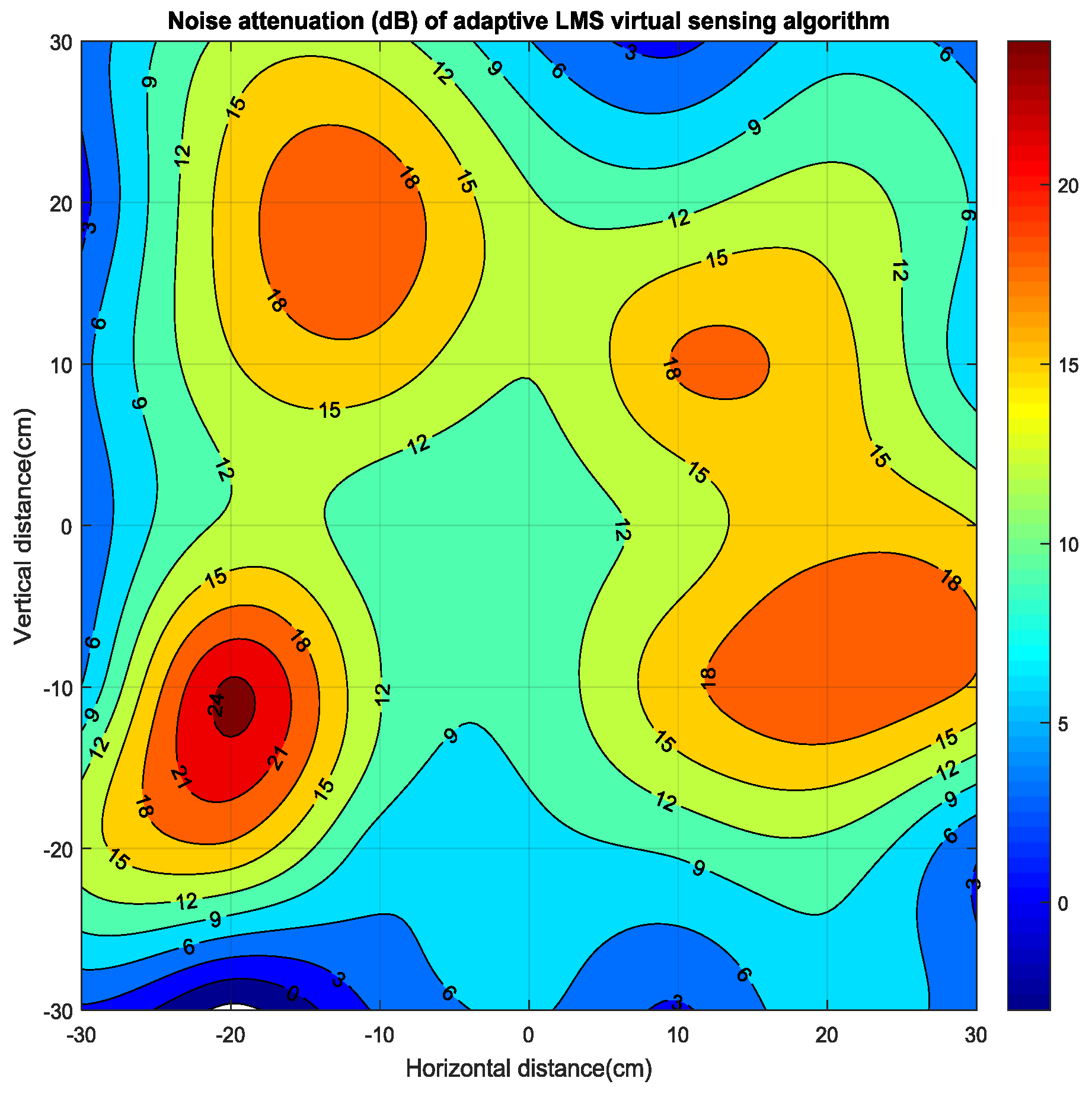
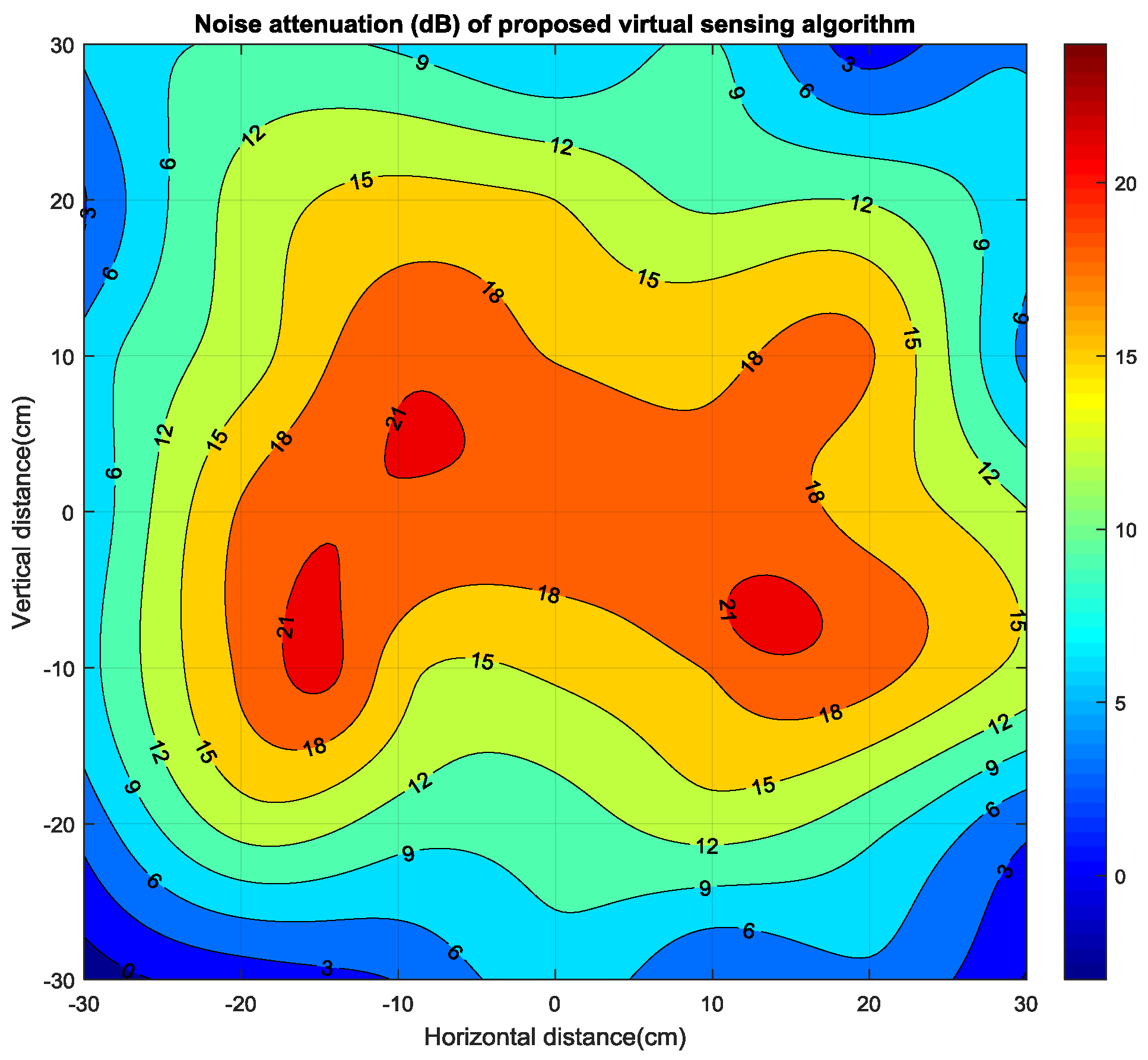
As we discussed before, if the unknown primary path is constantly varying, the adaptive LMS virtual sensing algorithm cannot maintain excellent performance. The quiet zone generated by the adaptive LMS virtual sensing algorithm in a varying environment is shown in Figure 9. The regions with the best noise reduction were created around four physical microphones, but the noise reduction at the target location significantly decreased. This implies that the effect of the virtual sensor in this condition is limited, so the system is more likely to generate quiet zones at the locations of four separate physical microphones individually. Figure 10 presents the quiet zone generated by the proposed virtual sensing algorithm in this condition. With the contribution of the proposed virtual sensor, the quiet zone has better continuity, especially around the target location. Thus, the performance of a virtual sensor is not affected by a varying environment.
In the third set of experiments, we considered a quiet zone generated using different microphone arrangements. We always assumed our target location was the origin. A virtual microphone was placed at (0, 0).
In Figure 11, the four physical error microphones are distributed as follows: (25, 25), (−25, 25), (−25, −25) and (25, −25). As can be seen in this figure, as the physical sensors moved toward the four vertexes of the square area, so did the regions with the best noise attenuation. At the same time, the noise reduction performance decreased in the middle part of the area. Compared with that in Figure 10, the region with 15 dB noise attenuation is not a connected region. However, with the contribution of the virtual sensor, the origin still performed relatively well. In fact, the noise reduction around the virtual location significantly decreased.
In Figure 12, the four physical error microphones are distributed as follows: (15, 15), (−15, 15), (−15, −15) and (15, −15). The distance between physical microphones shortened, and the region with high noise attenuation increased. The area with 18 dB noise attenuation became a conjoint region. However, as the physical sensors moved towards the center, the noise reduction on the edges of the square decreased.
The noise reduction performance of the virtual location and the central region can be obviously increased by shortening the distance between physical microphones. While the quiet zone is created for the human inside it, the microphone distance must be long enough such that people can move freely inside this quiet zone. Thus, a microphone distance that is overly short is not always a feasible or convenient solution. The level of noise reduction of the virtual location and the central region decreases as the distance between microphones increases, which means that a microphone distance that is too long is not workable. Thus, appropriate microphone arrangement has significant importance for every specific practical application.
5. Conclusions
The virtual sensing technique is utilized in ANC to enhance the noise attenuation in a given location. The adaptive LMS virtual algorithm is frequently used because of its simplicity and good performance, but its performance is significantly decreased when faced with a variable primary path. In this paper, a modified version of the adaptive LMS virtual sensing algorithm is proposed to solve this problem. The quiet zone generated by real-time ANC with the improved algorithm proves that the proposed system has good performance in a constantly changing environment.
Acknowledgments
This paper was supported by 2017 KoreaTech Professor Research Project.
Author Contributions
All authors have contributed to the work presented in this article. Xiangbin MU conceived and designed the proposed system, performed experiments, obtained the results and wrote the manuscript; JaeYeol RHEEM proposed the scheme, directed the work, analyzed and interpreted the obtained results and revised the manuscript.
Conflicts of Interest
The authors declare no conflict of interest.
References
- Kuo, S.M.; Morgan, D.R. Active Noise Control Systems: Algorithms and DSP Implementations; Wiley: New York, NY, USA, 1996; ISBN 0471134244. [Google Scholar]
- Antoñanzas, C.; Ferrer, M.; Diego, M.; Gonzalez, A. Blockwise frequency domain active noise controller over distributed networks. Appl. Sci. 2016, 6, 124. [Google Scholar] [CrossRef]
- Elliott, S.J.; Joseph, P.; Bullmore, A.J.; Nelson, P.A. Active cancellation at a point in a pure tone diffuse sound field. J. Sound Vib. 1988, 120, 183–189. [Google Scholar] [CrossRef]
- Mu, X.; Ko, J.; Rheem, J. Modified FXLMS algorithm for active noise control and its real-time implementation. J. Inst. Electron. Eng. Korea 2013, 50, 172–176. [Google Scholar] [CrossRef]
- Mu, X.; Ko, J.; Rheem, J. Performance improvement of a quiet zone using multichannel real-time active noise control system. J. Acoust. Soc. Korea 2016, 35, 216–222. [Google Scholar] [CrossRef]
- Cazzolato, B.S. An adaptive LMS virtual microphone. In Proceedings of the ACTIVE 2002, Southampton, UK, 15–17 July 2002; pp. 105–116. [Google Scholar]
- Das, D.; Moreau, D.; Cazzolato, B. A computationally efficient frequency-domain filtered-x LMS algorithm for virtual microphone. Mech. Syst. Signal Process. 2013, 37, 440–454. [Google Scholar] [CrossRef]
- Das, D.; Moreau, D.; Cazzolato, B. Performance evaluation of an active headrest using the remote microphone technique. In Proceedings of the Acoustics 2011, Gold Coast, Australia, 2–4 November 2011; pp. 1–7. [Google Scholar]
- Edamoto, S.; Shi, C.; Kajikawa, Y. Virtual sensing technique for feedforward active noise control. J. Acoust. Soc. Am. 2016, 140, 3313–3324. [Google Scholar] [CrossRef]
- Elliott, S.; David, A. A virtual microphone arrangement for local active sound control. In Proceedings of the 1st International Conference on Motion and Vibration Control, Yokohama, Japan, 7–11 September 1992; pp. 1027–1031. [Google Scholar]
- Garcia-Bonito, J.; Elliott, S.J.; Boucher, C.C. Generation of zones of quiet using a virtual microphone arrangement. J. Acoust. Soc. Am. 1997, 101, 3498–3516. [Google Scholar] [CrossRef]
- Moreau, D.; Ghan, J.; Cazzolato, B.; Zander, A. Active noise control with a virtual acoustic sensor in a pure-tone diffuse sound field. In Proceedings of the 14th International Congress on Sound and Vibration, Cairns, Australia, 9–12 July 2007. [Google Scholar]
- Moreau, D.; Cazzolato, B.; Zander, A.; Petersen, C. A Review of Virtual Sensing Algorithms for Active Noise Control. Algorithms 2008, 1, 66–99. [Google Scholar] [CrossRef]
- Mu, X.; Ko, J.; Rheem, J. Virtual sensor for multichannel real-time active noise control. In Proceedings of the IEIE Summer Conference, Jeju, Korea, 25 August 2014; pp. 768–771. [Google Scholar]
- Petersen, C.; Fraanje, R.; Cazzolato, B.; Zander, A.; Hansen, C. A Kalman filter approach to virtual sensing for active noise control. Mech. Syst. Signal Process. 2008, 22, 490–508. [Google Scholar] [CrossRef]
- Pawelczyk, M. Control algorithms for locating zones of quiet in the active headrest system. Mol. Quantum Acoust. 2002, 23, 339–350. [Google Scholar]
- Pawelczyk, M. Multiple input-multiple output adaptive feedback control strategies for the active headrest system: Design and real-time implementation. Int. J. Adapt. Control Signal Process. 2003, 17, 785–800. [Google Scholar] [CrossRef]
- Pawelczyk, M. Adaptive noise control algorithms for active headrest system. Control Eng. Pract. 2004, 12, 1101–1112. [Google Scholar] [CrossRef]
- Pawelczyk, M. Multi-channel virtual-microphone feedback minimum-variance active noise control system. Mechanics 2009, 28, 12–17. [Google Scholar]
- Roure, A.; Albarrazin, A. The remote microphone technique for active noise control. In Proceedings of the ACTIVE 1999, Fort Lauderdale, FL, USA, 2–4 December 1999; pp. 1233–1244. [Google Scholar]
- Ryu, S.; Lee, Y.S. Characteristics of relocated quiet zones using virtual microphone algorithm in an active headrest system. J. Sens. 2016. [Google Scholar] [CrossRef]
- Bouchard, M.; Norcross, S. Computational load reduction of fast convergence algorithms for multichannel active noise control. Signal Process. 2003, 83, 121–134. [Google Scholar] [CrossRef]
Figure 1.
Block diagram of multichannel delay-compensated filtered-x least mean square (FXLMS) algorithm.
Figure 1.
Block diagram of multichannel delay-compensated filtered-x least mean square (FXLMS) algorithm.
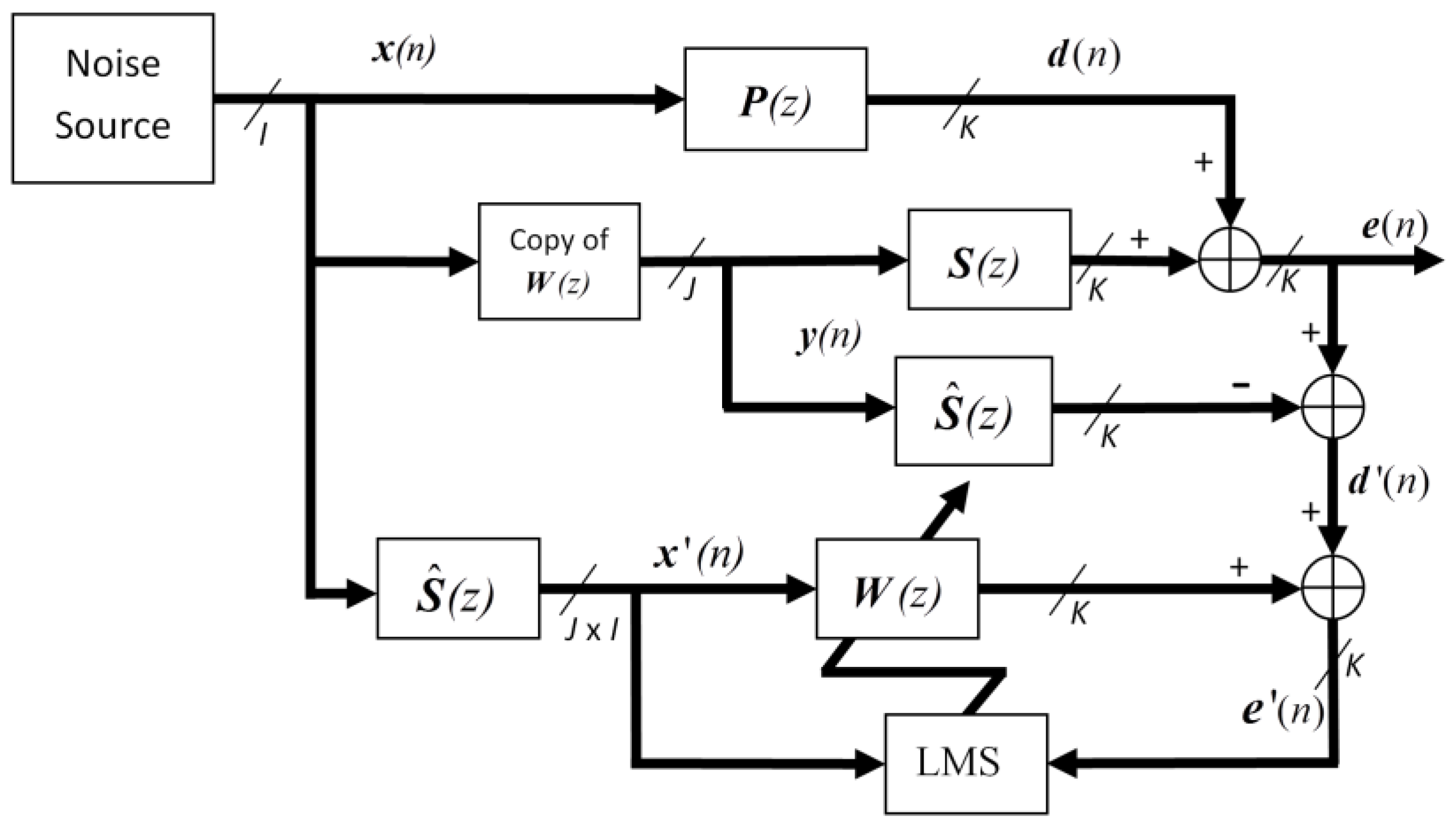
Figure 2.
The structure of multichannel real-time active noise control (ANC) system.
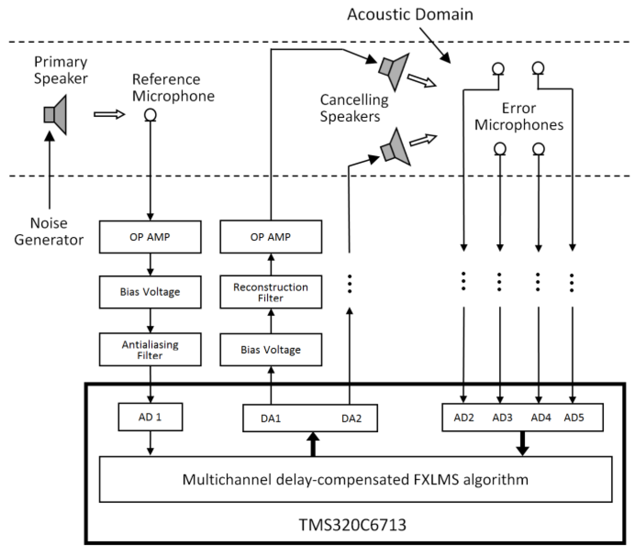
Figure 3.
The multichannel ANC with virtual sensor.

Figure 4.
Block diagram of the adaptive least mean square (LMS) algorithm to calculate microphone weights.
Figure 4.
Block diagram of the adaptive least mean square (LMS) algorithm to calculate microphone weights.
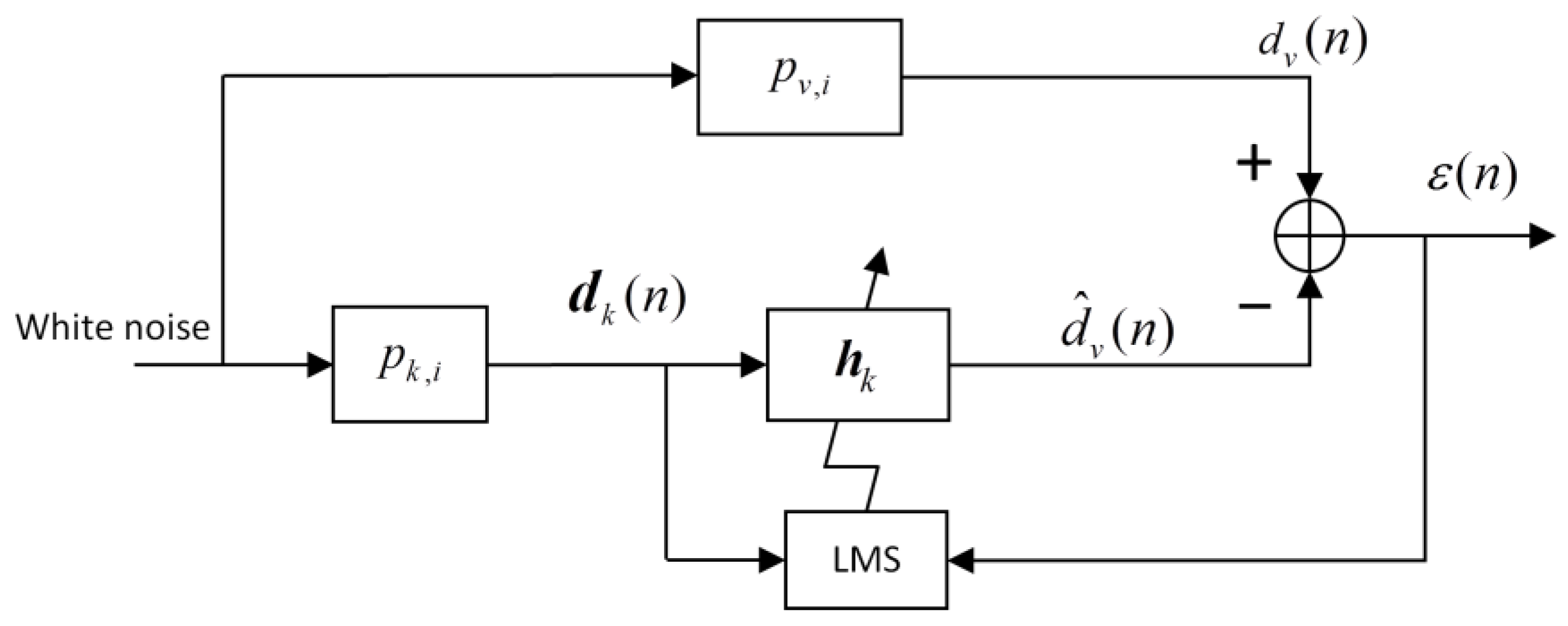
Figure 5.
Block diagram of the modified adaptive LMS algorithm to calculate microphone weights.

Figure 6.
System setup of the proposed ANC system.

Figure 7.
The quiet zone generated by multichannel ANC with the adaptive LMS virtual sensing algorithm in a stable environment.
Figure 7.
The quiet zone generated by multichannel ANC with the adaptive LMS virtual sensing algorithm in a stable environment.

Figure 8.
The quiet zone generated by multichannel ANC with the proposed virtual sensing algorithm in a stable environment.
Figure 8.
The quiet zone generated by multichannel ANC with the proposed virtual sensing algorithm in a stable environment.
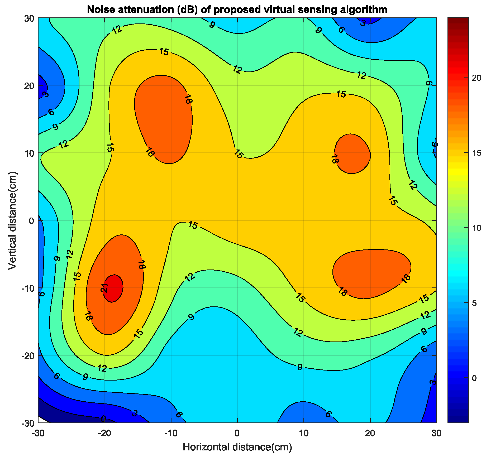
Figure 9.
The quiet zone generated by multichannel ANC with the adaptive LMS virtual sensing algorithm in the varying environment.
Figure 9.
The quiet zone generated by multichannel ANC with the adaptive LMS virtual sensing algorithm in the varying environment.

Figure 10.
The quiet zone generated by multichannel ANC with the proposed virtual sensing algorithm in the varying environment.
Figure 10.
The quiet zone generated by multichannel ANC with the proposed virtual sensing algorithm in the varying environment.
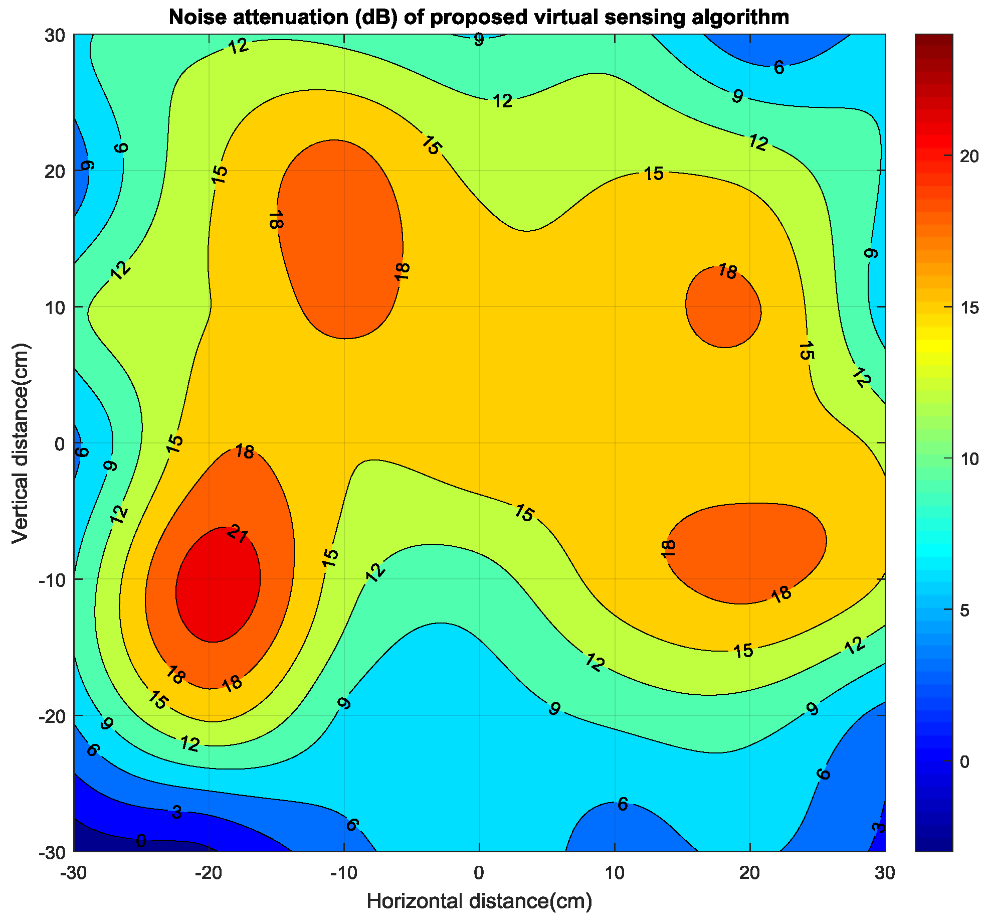
Figure 11.
The quiet zone generated by the proposed algorithm with physical microphones located at (25, 25), (−25, 25), (−25, −25) and (25, −25).
Figure 11.
The quiet zone generated by the proposed algorithm with physical microphones located at (25, 25), (−25, 25), (−25, −25) and (25, −25).
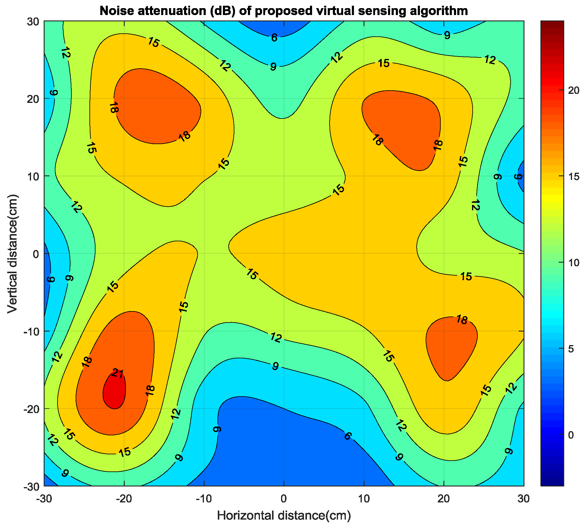
Figure 12.
The quiet zone generated by the proposed algorithm with physical microphones located at (15, 15), (−15, 15), (−15, −15) and (15, −15).
Figure 12.
The quiet zone generated by the proposed algorithm with physical microphones located at (15, 15), (−15, 15), (−15, −15) and (15, −15).

© 2017 by the authors. Licensee MDPI, Basel, Switzerland. This article is an open access article distributed under the terms and conditions of the Creative Commons Attribution (CC BY) license (http://creativecommons.org/licenses/by/4.0/).
Share and Cite
MDPI and ACS Style
Mu, X.; Rheem, J. Quiet Zone Enhancement for a Target Location Using an Improved Virtual Sensing Algorithm. Electronics 2017, 6, 76. https://doi.org/10.3390/electronics6040076
AMA Style
Mu X, Rheem J. Quiet Zone Enhancement for a Target Location Using an Improved Virtual Sensing Algorithm. Electronics. 2017; 6(4):76. https://doi.org/10.3390/electronics6040076
Chicago/Turabian StyleMu, Xiangbin, and JaeYeol Rheem. 2017. "Quiet Zone Enhancement for a Target Location Using an Improved Virtual Sensing Algorithm" Electronics 6, no. 4: 76. https://doi.org/10.3390/electronics6040076
Note that from the first issue of 2016, this journal uses article numbers instead of page numbers. See further details here.