Low-Complexity PAPR Reduction Scheme Combining Multi-Band Hadamard Precoding and Clipping in OFDM-Based Optical Communications


1
School of Electronic and Information Engineering, Qingdao University, 308 Ningxia Road, Qingdao 266071, China
2
School of Information Science and Engineering, Southeast University, Nanjing 210096, China
3
School of Electronic Information, Shanghai Dianji University, Olive Road, Shanghai 200240, China
*
Author to whom correspondence should be addressed.
Electronics 2018, 7(2), 11; https://doi.org/10.3390/electronics7020011
Submission received: 24 December 2017
/
Revised: 16 January 2018
/
Accepted: 17 January 2018
/
Published: 23 January 2018
Abstract
:In this paper, we propose a low-complexity peak-to-average power ratio (PAPR) reduction scheme that combines both multi-band (MB)-Hadamard precoding and clipping for the optical orthogonal frequency division multiplexing (OFDM) systems. Approximations of PAPR distribution for baseband OFDM signals are analyzed and the effective signal-to-noise ratio (SNR) of the whole transmission link considering both the clipping and quantization noise are presented. After that, the MB-Hadamard precoding is adopted to compresses the peak signals, minimizing the contaminating influence of signal distortions in subsequent clipping operations. In addition, the received SNRs and bit error rate (BER) are calculated theoretically for each split sub-band. The 50-m step-index polymer optical fiber (POF) transmission is adopted as a special case to both evaluate the system performance and then compare the proposed scheme with other well-known PAPR reduction techniques. With this scheme, the PAPR is reduced effectively and the system’s BER performance is improved significantly. The results show that the proposed scheme with appropriate number of sub-bands precoding provides favorable trade-offs among PAPR reduction, power spectral density, transmission rate, BER, and computational complexity, which demonstrates its feasibility and validity.
1. Introduction
Orthogonal frequency division multiplexing (OFDM) is regarded as a promising modulation candidate for optical wireless communication (OWC) and polymer optical fiber (POF) as it provides a high data rate, high spectral efficiency, and high tolerance to multi-path interference [1,2]. A baseband OFDM with Hermitian symmetry property, as in [3,4], is also called discrete multi-tone (DMT). For simple and low cost consideration, the DMT can be employed in optical communications using the intensity modulation with direct detection (IM/DD) technique and bit-loading algorithm to maximize the system capacity [4,5,6]. However, the DMT suffers from a high peak-to-average power ratio (PAPR) and is more susceptible to nonlinear distortions. Since the light-emitting diode (LED) has a limited linear dynamic range, the DMT signals with high PAPRs drive the LED at the transmitter to saturation, producing a greater number of nonlinear distortions and degrading the overall system performance [7,8,9]. Therefore, the PAPR of the DMT should be reduced so that the LED can operate linearly and power efficiently [10].
Several PAPR reduction techniques have been proposed for wireless communication systems [11,12,13,14,15,16,17,18]. In general, these techniques can be broadly categorized into signal distortion, distortionless, and coding schemes. Clipping, filtering and companding are well-known varieties of signal distortion schemes that directly limit the peak envelope of the transmitting signals to a desired value [13,14,15]. However, these signal processing schemes result in both in-band distortion and out-of-band high frequency components, which further degrades the bit error rate (BER) performance and reduces the spectral efficiency. Selective mapping (SLM), and partial transmit sequence (PTS) are typical distortionless schemes [16,17,18] that improve the PAPR distribution statistically and provide pretty good PAPR performance. However, they all have very high computational complexities and require the receivers to know the side information to retrieve the original data blocks. In addition, it is complicated to design the phase vectors for both SLM and PTSs. The coding changes their original codewords to reduce their PAPRs with high operational complexities. Tone reservation and tone injection are effective approaches to mitigate the PAPR problem [11]. However, due to their computational complexity, the challenge is to find the optimal subset and it becomes intractable for OFDM systems with a large number of subcarriers. In addition, the transmission rate is also degraded. Schemes such as active constellation extension introduce redundancy as well [12]. In particular, these methods used in radio wireless communication cannot be directly adopted in optical systems because of the real value property in IM/DD implementation. In contrast, discrete Fourier transform spreading (DFT-S) is an efficient method of reducing the PAPR without causing any distortion noise [8]. Nevertheless, DFT-S-DMT still exhibits a high PAPR because of the Hermitian symmetry requirement of the IM/DD channel. In addition, each subcarrier of DFT-S-DMT obtains the same signal-to-noise ratio (SNR) after the equalization and dispreading procedure, indicating that it is unsuited to apply the bit-loading with DFT-S-DMT in the frequency selective channel to achieve overall system capacity. Moreover, DFT-S-DMT is extremely sensitive to LED nonlinearity, which limits its practical applications. The discrete Hartley transform (DHT)-spread approach exhibits a lower PAPR compared to DFT-spread techniques. However, it is only applicable to real constellations such as pulse amplitude modulation (PAM) and the PAPR reduction capability decreases with an increase in size of the PAM alphabet.
In this paper, an efficient low-complexity PAPR reduction scheme combining both multi-band (MB)-Hadamard precoding and clipping is proposed in DMT systems. The modulated symbols of a split sub-band are pre-coded by MB-Hadamard matrix to compress the peak signals of the DMT, which would mitigate the signal distortions of the following clipping operation. The received SNRs and BERs are also calculated for each split bands. The results demonstrated that the proposed scheme reduces the PAPR significantly and improves the BER performance effectively. Moreover, it matches well with the bit-loading technique to enhance the system capacity. In addition, some other famous PAPR reduction approaches are also compared and discussed.
The remainder of this paper is organized as follows. In Section 2, we briefly present the PAPR characteristics of the DMT. In Section 3, the effective SNR of the whole IM/DD channel considering both the clipping and the quantization is analyzed. In Section 4, a hybrid PAPR reduction scheme is proposed to compress the peak signals and then limit the PAPR to a given threshold level. Section 5 presents the results and discusses them, and Section 6 concludes the paper.
Notations: the time and frequency domain vectors are represented by lower and upper boldface italic letters (e.g., and ), respectively. The element of the column vector is denoted as . Upper-case boldface letters (e.g., ) denote matrices, and , , , , and are the expectation, the transpose, complex conjugate, absolute value, real component, and symmetric conjugate operator, respectively. Let denotes the Gaussian distribution with a mean of and a variance of .
2. DMT and PAPR
With respect to a DMT symbol with sub-carriers, the data stream is mapped onto based on the quadrature amplitude modulation (QAM) constellation. Then, the time domain DMT signal is generated by a -point inverse discrete Fourier transform (IDFT), given by [4,5,6,7]:
where conforms to Hermitian symmetry [4] to produce the real-valued time-domain signal . According to the central limit theorem, for , can be modeled as a Gaussian distribution with .
The PAPR of is defined as the ratio between the maximum peak power and the average power during one symbol period, which can be written as [5,19]
Based on the central limit theorem, we can obtain
where , denotes the probability, and denotes the threshold. Therefore, the complementary cumulative distribution function (CCDF) can be calculated as
Continuous-time DMT signal can be represented approximately by the times oversampled . Based on the extreme value theory, the corresponding CCDF can be calculated by
where is the PAPR of . Study [11] demonstrates that selecting is sufficient for approximating the peak value of .
Taking the discrete-time DMT as an example, the instantaneous power of can be calculated by
where is defined as the aperiodic autocorrelation function (ACF) of . For an arbitrary complex , the following inequalities hold and . Thus, a PAPR with a unit mean power () satisfies
where . Therefore, a close relationship exists between and . When the input symbols are all equal, is able to reach its maximum value within one symbol duration.
3. The Effective SNR
Due to both the high PAPRs of DMT signals and the finite dynamic ranges of digital-to-analog conversion (DAC) devices, digital clipping for the given upper and lower thresholds is usually performed before DAC. The clipped signal is given as [5]
For simplicity, we consider symmetric clipping (). The clipping ratio (CR) is defined as
The output of clipping process can be considered as the sum of and the clipping noise :
Nevertheless, based on the Bussgang theorem [20] for Gaussian inputs , the clipped signal can also be decomposed statistically into two uncorrelated parts, given by
where is the component of clipping distortion that is statistically uncorrelated to (e.g., ), and is a linear attenuation factor that can be calculated by
where . The power of can be obtained by
Therefore, is a function of and is independent of both the QAM modulation order and the size of IFFT/FFT. is converted into the analog signal by the DAC component. Due to the finite bit resolution of the DAC, the quantization noise is then generated. The corresponding power can be calculated as
To modulate the LED, is added by DC current and obtain the final driving signals. We assume that the DMT signal is properly clipped, avoiding the LED nonlinearity. After optical channel transmission, the optical signal is detected by the optical detector, a combination of a photo diode (PD) and a trans-impedance amplifier (TIA). In most of the cases, the main sources of noise in the optical detector can be modeled as an additive white Gaussian noise (AWGN) following the distribution as . Then, the received electrical signal is captured by analog-to-digital conversion (ADC) components with bits of resolution. The power of the quantization noise in the ADC is given as
where is the optical path gain coefficient. For simplicity, , and are adopted in analysis. Finally, the total noise power in IM/DD channel link can be approximately measured with . Therefore, the system performance can be evaluated by as the ratio between the power of the useful signal and the effective noise power, expressed as
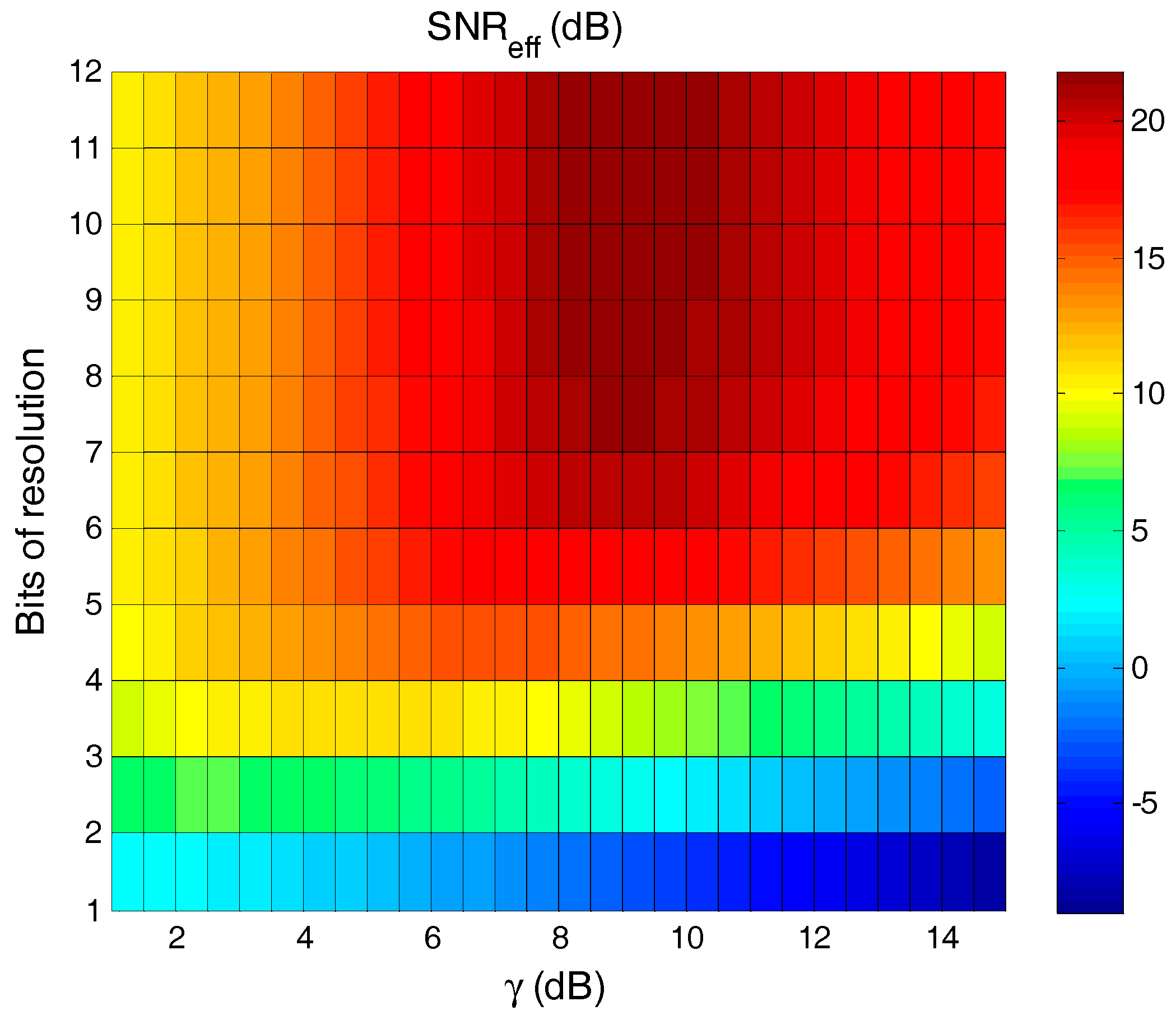
For , and , the characteristic behavior of with different and is depicted in Figure 1. It can be observed that the can achieve its maximum value regarding to the optimum clipping for each , e.g., dB for = 8. Once the is computed, the BER performance of the DMT system can be easily evaluated with the help of the exact close-form expression of the QAM in AWGN channel [21]. As Figure 1 demonstrates, the degradation caused by the quantization is negligibly small when both and are greater than seven. In addition, the clipping effect dominates the system’s as the and threshold is fixed. Therefore, if we perform an appropriate method for reducing the of the input , then, a transmitted signal with a lower is obtained and the probability of the exceeding a given within one symbol duration is reduced. This indicates that the can be lowered accordingly. Motivated by this way, a novel DMT scheme is proposed in the followings to reduce the value of , thus indirectly reducing the PAPR and improving the .
4. Proposed Scheme
A block diagram of the proposed scheme is shown in Figure 2. Compared with the conventional DMT (C-DMT), two additional modules, extra MB-Hadamard precoding and clipping, are implemented at the transmitter. Hadamard is a class of Jacket matrix [22,23,24] which are simple to calculate and easily element-wise inverse.
Assuming signifies a unit Hadamard matrix, the inverse Hadamard matrix can be calculated directly using
For example,
where denotes the matrix order. Note that the Hadamard matrix with an order of the power-of-2 is adopted in this paper.
Assuming that there are sub-carriers, is the data symbol in the band. The original symbol is spread by an Hadamard matrix firstly, and then a new set symbols is generated with
where is an element of and are sub-band mapped onto the -point symbol vector, expressed by
where are the modulated symbols according to the sub-band constellation mapping, expressed as
In addition, the vector is obtained by performing Hermitian symmetry, and then fed into to the IFFT block to generate the time domain signals . By introducing both the ACF expression from Equation (6) and the ACF sum from Equation (7), we can arrive at
Note that Equation (22) will be verified by the numerical result which is demonstrated in the Section 5.1. Furthermore, approaches an approximate Gaussian distribution as the value of is large enough. The reduction in implies a lower value of . Thus, we obtain
According to Equation (7), there is a close relationship between and the correlations of the input frequency-domain data-symbols. Therefore, the more can be reduced, the lower the PAPR value and the higher the can be obtained by MB-Hadamard precoding. After that, the precoded DMT is added with cyclic prefix (CP) and then fed into the clipping module to further reduce the peaks. In addition, we can also perform the filtering procedure iteratively to both remove the out-of-band interference and suppress the regrowth of the peak power.
The received optical signal is transformed into an electrical signal by the PD detector. Note that the quantization noise is negligibly small when the bit resolution is greater than seven. After the FFT and CP removal, the digital received symbol in the frequency domain can be approximately expressed with a matrix form as
where is the frequency domain channel response, is the in the frequency domain and is channel noise. In what follows, the perfectly known channel response and the perfect synchronization in the demodulation process are assumed for every received frame. After zero-forcing equalization, the equalized symbol can be expressed as
With the Hermitian symmetric data of removed, the new received symbol is generated. Then, is fed into the MB-Hadamard decoding module. A diagram of the proposed decoding operation is depicted in Figure 3, where the demodulation procedure is the reverse of those used in (19)–(21). After the sub-band demapping is completed, is transformed by the inverse Hadamard matrix and the final data symbol is obtained. Then, a maximum likelihood (ML) estimator is adopted as
where is constellation point of QAM and is the constellation size.
When bit-loading with the desired BER is employed, the SNR for each split band can be represented by
where is the average noise power per subcarrier, is the modulation gap, and denote the channel response and the allocated power at the subcarrier in the band, respectively. As we known, the clipping will introduce the offensive impulse noise among in-band and out-band. Fortunately, as seen in Equation (27), the system noise is spread averagely in each sub-band and the corresponding SNR gains will be achieved by the MB-Hadamard decoding, which is favorable for symbol estimation. When a uniform power allocation is adopted for each sub-band and the total used power is , then can be calculated as . Therefore, for a frequency-selective channel such as a POF, the SNR of the entire transmission band can be written as
As shown in Equations (27) and (28), the values within the same sub-band are equal, whereas those of adjacent sub-bands are different. Under these circumstances, it is appropriate to apply the bit-loading technique to each sub-band, which represents the primary difference between the proposed scheme and the DFT-S-DMT with respect to bit loading. Finally, the BER of the MB-Hadamard decoding in the band can be approximately calculated as
5. Results and Discussion
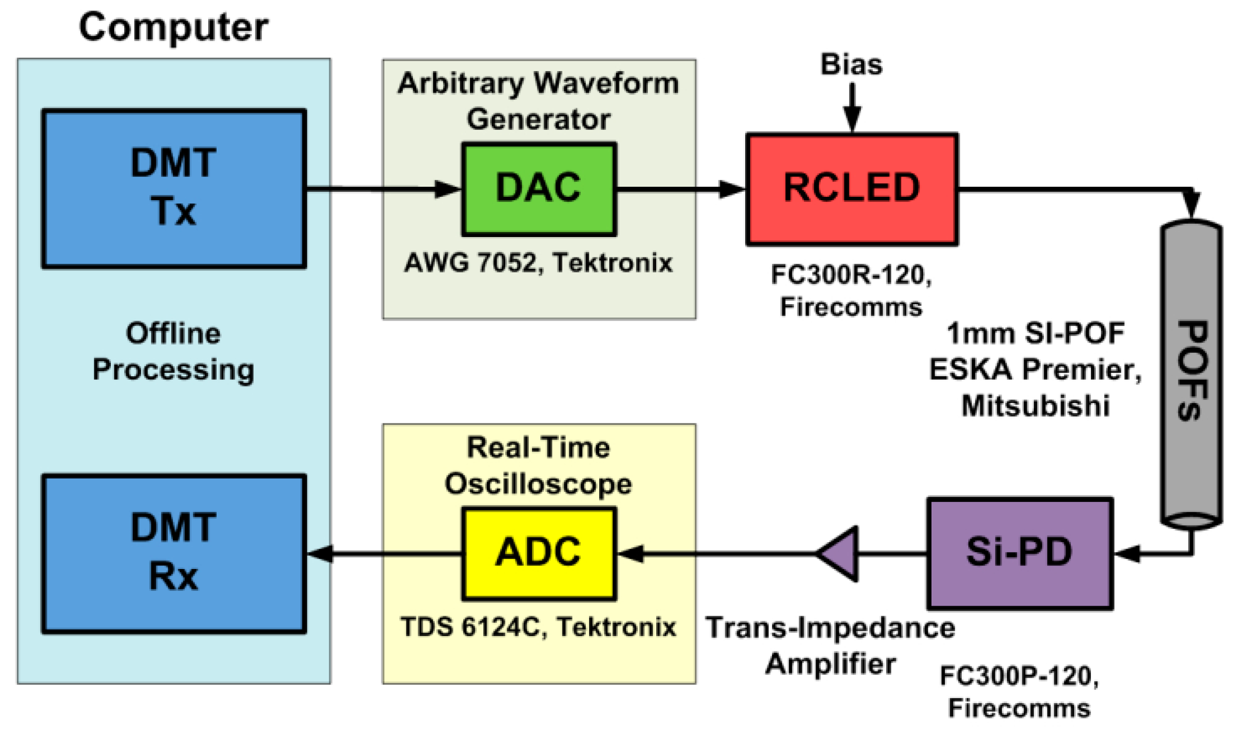
In this section, the performance of the proposed scheme over an IM/DD optical channel is investigated and evaluated in terms of its PAPR, power spectral density (PSD), achievable transmission rate, BER and complexity. The POF transmission setup is depicted in Figure 4. Ten-bit DAC and eight-bit ADC are both adopted, resulting in negligible quantization noise. A standard 50-m Polymethyl Metacrylate (PMMA) step index (SI) POF (150 dB/km @650 nm) is employed. The DMT signals are pre-generated by a computer and stored in the arbitrary waveform generator (AWG) memory. The analogue electrical signal of the AWG output is then used to drive a 650-nm RC-LED with a 10-mA bias current. After the SI-POF transmission, the received optical signal is detected by the PD and then captured by the ADC components. Finally, digital signal processing is implemented in MATLAB. With respect to the received probing symbols, the estimated channel information is obtained and the normalized noise PSD is measured at approximately −110 dB/Hz, which will be used in the following simulations. The DMT parameters are depicted in Table 1.
5.1. PAPR Reduction
To assess the performance of the MB-Hadamard precoding in reducing the PAPR, the 512 value is adopted from Table 1, and the signal bandwidth is calculated to be approximately 250 MHz. In our simulations, 4000 DMT symbols are generated randomly. Figure 5 shows the signal amplitudes of our proposed scheme for various sub-band numbers as well as the signal amplitude of C-DMT. As shown in the figure, the signal amplitude is reduced significantly by the proposed MB-Hadamard precoding for the cases of 1, 4 and 8. In addition, the energy distribution becomes more uniform, and most of the large amplitudes are compressed below the clipping threshold, which indicates that the signal distortion in the following clipping could be mitigated to some extent.
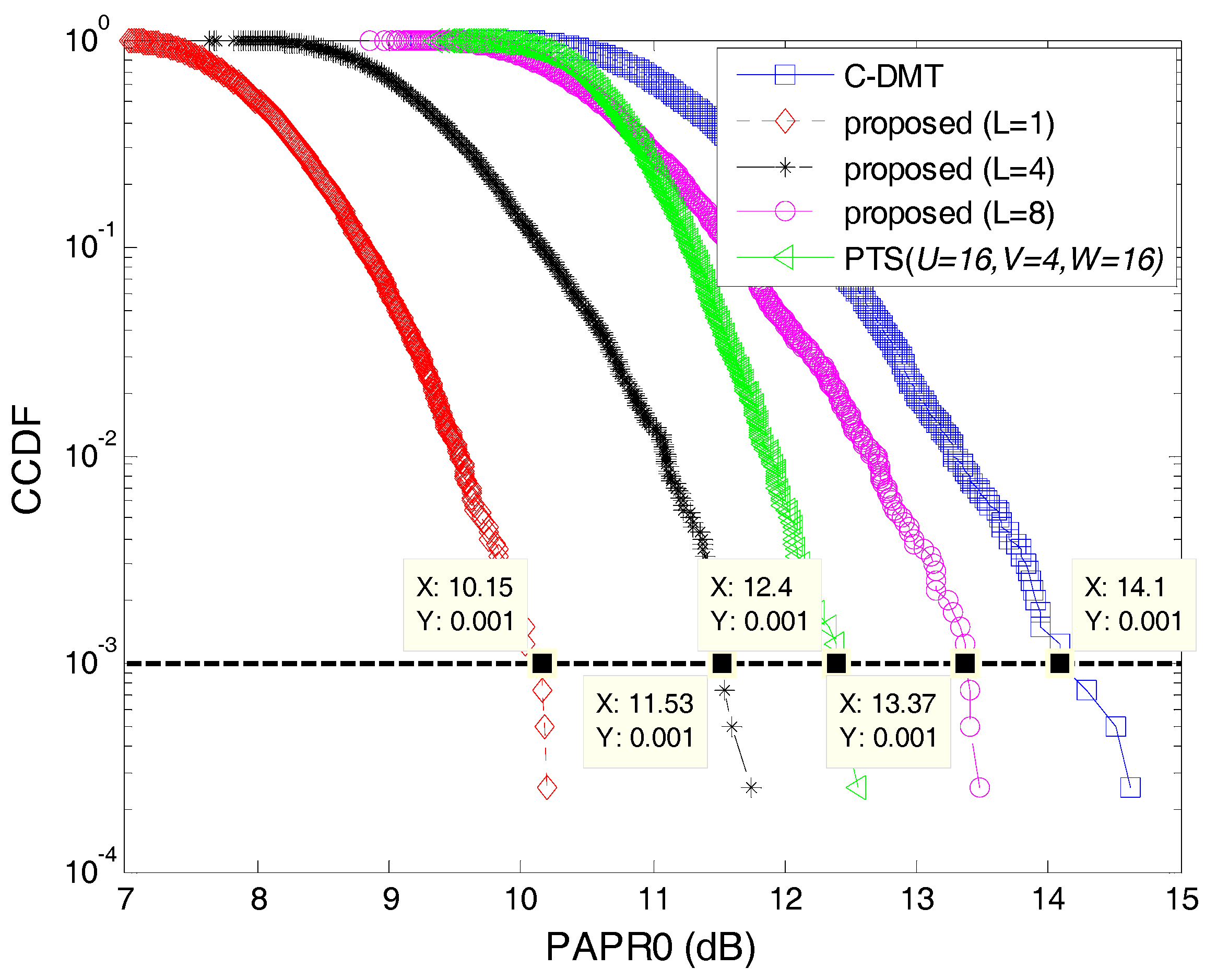
Figure 6 illustrates the CCDF performance of the proposed scheme. As shown in the figure, the C-DMT scheme achieves the highest PAPR; however, the smaller the band split (e.g., ), the lower the PAPR obtained by the proposed. When the CCDF = 10−3, the PAPR of the C-DMT is 14.1 dB, whereas those of the proposed are 10.15 dB and 11.53 dB for 1 and 4, respectively, resulting in respective 3.95 dB and 2.57 dB performance improvements. In addition, the figure also indicates that the CCDF performance of the proposed scheme with 8 improves little because an insufficient volume of reliable data exists in the split band, which affects the correlations of the input symbols. The CCDF of a well-known PTS in which the parameters , and denote the numbers of corresponding modified candidate sequences, disjoint sub-vectors and phase angles, respectively, is also demonstrated. The PAPR performance of the PTS exceeds that of C-DMT but is inferior to those of the proposed scheme for both 1 and 4.
The calculated values with respect to both the C-DMT and the proposed scheme under various values of are shown in Figure 7a, which illustrates that these curves move gradually away from the C-DMT as decreases. As seen in the figure, the corresponding relationship can easily be obtained based on the definition of give in Equation (6). Taking 512 as an example, the calculated probability density function (PDF), in terms of both and , is shown in Figure 7b. The figure reveals that the curves have similar shapes and are approximately Gaussian distributed. Compared to , and are decreased, which implies that the MB-Hadamard precoding reduces the PAPR effectively. In addition, as discussed in Section 4, the establishment of inequalities Equations (22) and (23) are also verified by the results shown in Figure 7.
5.2. PSD Performance
Figure 8 depicts a comparison of the PSD performances for the MB-Hadamard precoding under various band numbers . As shown in the figure, the rectangular PSD characteristics of the DMT are maintained, which indicates that the MB-Hadamard precoding neither affects the signal PSD nor damages the spectral efficiency. Furthermore, the sideband spectrum is reduced, which is advantageous for hybrid signal transmissions in short range POF systems.
5.3. Achievable Transmission Rate
To maximize the capacity of the POF system, the split sub-band number must first be evaluated. Both a fixed electrical power of six decibel-milliwatts and a 10-mA biasing current are used for the practical transmission. The CR is maintained at a constant dB. In addition, the Chow bit-loading algorithm [25] with a BER target of is adopted. The number of sub-carriers varies with the fixed spacing MHz. Note that channel coding is not used in this study.
For various signal bandwidths between 50 MHz and 500 MHz, the total achievable transmission rates of the C-DMT and the proposed scheme with 1, 4, and 8 are compared in Figure 9a. Both the proposed scheme and the C-DMT can achieve their maximal transmission rates based on the optimal signal bandwidth , which varies along with . In the case of 1, the optimal bandwidth range is limited between approximately 150 MHz and 200 MHz due to the achievable transmission rate is sensitive to the signal bandwidth. In addition, the performance is severely degraded when the used bandwidth exceeds the . The for both 4 and 8 are wider than that of 1. In addition, compared to the C-DMT, the transmission rate of the proposed scheme with = 4 improves by at least eight percent, and its highest transmission rate is achieved at approximately 1.204 Gbps for 228 MHz. For this case, the corresponding bit and power distributions of each sub-carrier are depicted in Figure 9b. As discussed in the previous section, each subcarrier in the same sub-band obtains the same value after both equalization and dispreading have taken place. Therefore, based on the calculations of the Chow algorithm [25], both equal numbers of the modulated bits and equal amounts of power are allocated to each sub-carrier in the same sub-band, even in a frequency selective channel such as the POF. As shown in the figure, there also exists some slight distinction of the bit and power allocations in the last sub-band because the target number of total bits has already nearly been allocated by the previous sub-carriers, leading to fewer bits being assigned to the last sub-carrier (e.g., a single bit could be enough). In addition, the effective SNR distribution among the sub-carriers for the proposed scheme ( 4) is depicted in Figure 9c. As seen in the figure, the overall SNR gain of the system is achieved obviously by the proposed scheme compared the C-DMT at the same clipping threshold.
Stated thusly, a moderate can guarantee both the validity and the feasibility of the proposed scheme as well as maximize the transmission rate, which is more important for a practical transmission system. Note that the proposed scheme chooses the optimal according to the actual signal bandwidth.
5.4. BER Performance
The BER performances of the C-DMT (clipping-only), Golay complementary sequences (GCSs) [12], and PTS are carefully investigated and discussed in this section. To provide a fair comparison, the transmitting signals have the same modulation parameters as those depicted in Table 1, and the number of sub-carriers is used. The Chow algorithm with and a desired transmission rate of 1.0 Gbps is also adopted. In addition, the CR is chosen to be dB and the input electrical signal power is varied from −2–6 decibel-milliwatts.
As shown in the Figure 10, the GCS offers the lowest BER because of its excellent error-correction ability. Clipping in the C-DMT is the simplest way to reduce the PAPR, whereas the BER is limited by . The proposed scheme with 4 provides a better BER performance than the C-DMT, and the required signal power is reduced at least by four decibel-milliwatts for the given BER = . Compared to the C-DMT, smaller clipping distortion is generated in the proposed scheme because most of the large signal amplitudes are compressed. The PTS also achieves a better BER performance. However, the side information of PTS must be known by the receiver. If this information fails to be detected, the demodulator cannot recover the original signal correctly and the BER performance degrades accordingly.
5.5. Computational Complexity
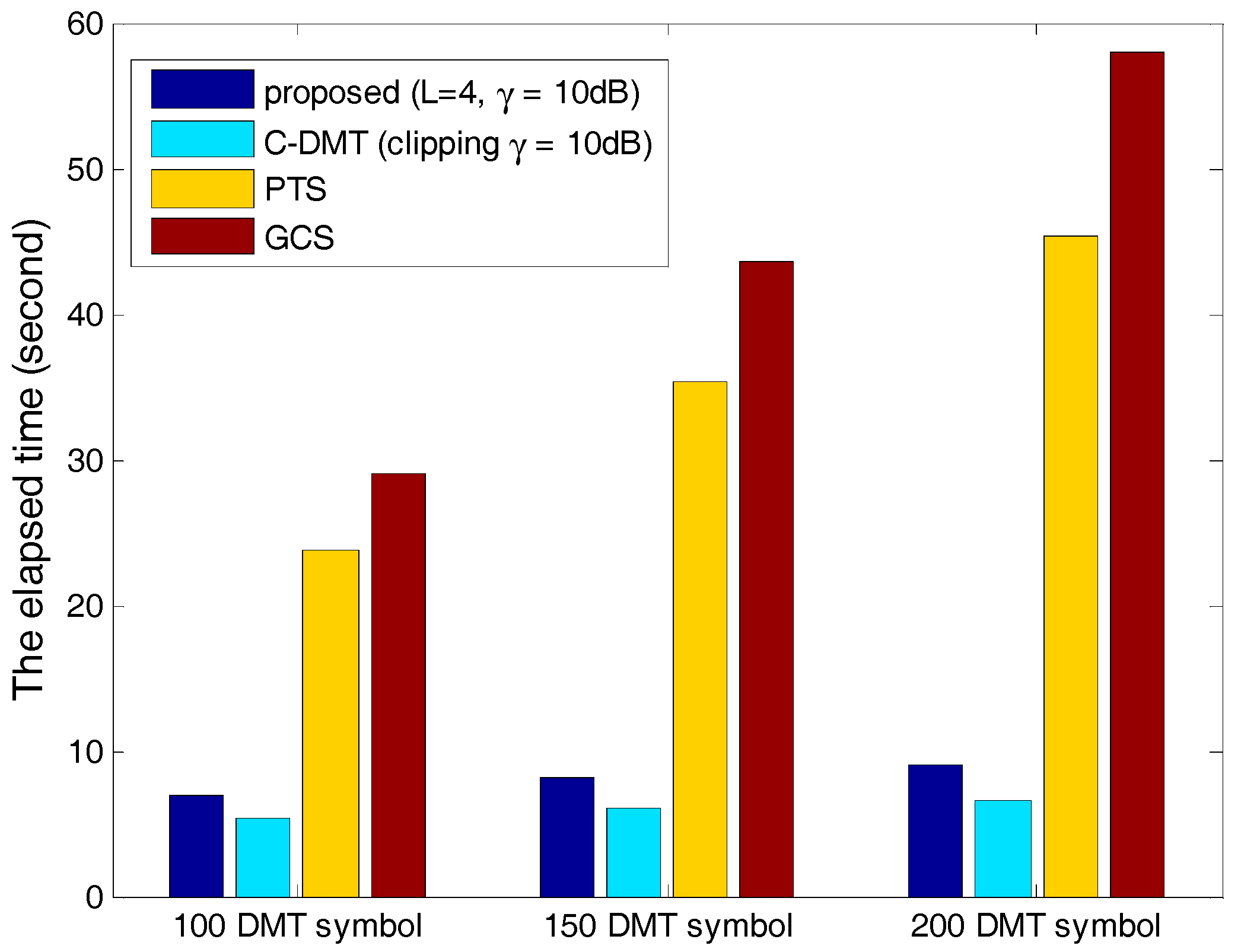
The elapsed signal processing time , representing the total time consumed by both the signal generation and the demodulation, is adopted as a metric to measure the computational complexity performance. In this study, 100, 150, and 200 DMT symbols each are performed in the transmissions. The value of for various schemes are measured and then shown in Figure 11. The figure illustrates that the PTS and GCS schemes require the longest signal processing times, and the corresponding values of increase dramatically with an increase in the number of DMT symbols used. In addition, many times of IFFT computations are required in the PTS scheme to find its optimum combination of phase factors. GCS also has more difficulty in seeking the optimum generated matrix and phase rotation vectors as greater numbers of subcarriers are used. In addition to these overhead loads, many more complex adder and multiplier have to be performed in both the PTS and the GCS, which consumes more hardware resources and requires more time. However, the of the proposed scheme is shorter and changes very little as the number of symbols used increases, meaning that a lower computational complexity is obtained. The additional operations performed in the proposed scheme consist entirely of spreading and dispreading, which are both easily employed and convenient for hardware implementation.
In summary, the proposed scheme is beneficial to the high-speed data transmission from the carefully performance investigation of the PAPR, the BER, the transmission rate, the PSD and the computational complexity.
6. Conclusions
In this paper, an efficient low-complexity scheme using both MB-Hadamard precoding and clipping was proposed to reduce the PAPRs of OFDM-based systems. By implementing this methodology, the peak signal was compressed and the PAPR was reduced as a consequence. In addition, the nonlinear distortions caused by clipping were effectively mitigated, and the BER performance was improved significantly. Moreover, it improves the robustness of the Hadamard precoding to system nonlinearity and sets the optimal sub-band number according to the actual signal bandwidth. The results demonstrate that the proposed scheme can provide favorable trade-offs among the PAPR, BER, transmission rate, complexity, and spectral efficiency. A further degree of experimental verification will be investigated in the future works.
Acknowledgments
The authors acknowledge the support for this work from the National Natural Science Foundation of China (61601281). We would like to express gratitude to Lenan Wu and Linning Peng that constructive suggestions and assistance to this article.
Author Contributions
Pu Miao, Peng Chen and Zhimin Chen conceived and designed the simulations and experiments; Pu Miao and Peng Chen analyzed the data; Zhimin Chen contributed figures plotting; Pu Miao wrote the paper.
Conflicts of Interest
The authors declare no conflict of interest.
References
- Okonkwo, C.M.; Tangdiongga, E.; Yang, H.; Visani, D.; Loquai, S.; Kruglov, R.; Charbonnier, B.; Ouzzif, M.; Greiss, I.; Ziemann, O.; et al. Recent Results from the EU POF-PLUS Project: Multi-Gigabit Transmission Over 1 mm Core Diameter Plastic Optical Fibers. J. Lightwave Technol. 2011, 29, 186–193. [Google Scholar] [CrossRef]
- Guariglia, E. Entropy and Fractal Antennas. Entropy 2016, 18, 84. [Google Scholar] [CrossRef]
- Chen, L.; Krongold, B.; Evans, J. Performance Analysis for Optical OFDM Transmission in Short-Range IM/DD Systems. J. Lightwave Technol. 2012, 30, 974–983. [Google Scholar] [CrossRef]
- Peng, L.; Helard, M.; Haese, S. On Bit-Loading for Discrete Multi-Tone Transmission over Short Range POF Systems. J. Lightwave Technol. 2013, 31, 4155–4165. [Google Scholar] [CrossRef]
- Azim, A.W.; Guennec, Y.L.; Maury, G. Decision-directed iterative methods for PAPR reduction in optical wireless OFDM systems. Opt. Commun. 2017, 389, 318–330. [Google Scholar] [CrossRef]
- Stepniak, G. DMT Transmission in SI POF with Minimax Channel Shortening Equalizer. IEEE Photonics Technol. Lett. 2014, 26, 1750–1753. [Google Scholar] [CrossRef]
- Zhang, G.; Zhang, J.; Hong, X.; He, S. Low-complexity frequency domain nonlinear compensation for ofdm based high-speed visible light communication systems with light emitting diodes. Opt. Express 2017, 25, 3780–3794. [Google Scholar] [CrossRef] [PubMed]
- Karabetsos, S.; Pikasis, E.; Nikas, T.; Nassiopoulos, A.; Syvridis, D. DFT-Spread DMT Modulation for 1-Gb/s Transmission Rate Over 100 m of 1-mm SI-POF. IEEE Photonics Technol. Lett. 2012, 24, 836–838. [Google Scholar]
- Karunatilaka, D.; Zafar, F.; Kalavally, V.; Parthiban, R. Led based indoor visible light communications: State of the art. IEEE Commun. Surv. Tutor. 2015, 17, 1649–1678. [Google Scholar] [CrossRef]
- Ying, K.; Yu, Z.; Baxley, R.J.; Qian, H.; Chang, G.K.; Zhou, G.T. Nonlinear distortion mitigation in visible light communications. IEEE Wirel. Commun. 2015, 22, 36–45. [Google Scholar] [CrossRef]
- Lim, D.W.; Heo, S.J.; No, J.S. An overview of peak-to-average power ratio reduction schemes for OFDM signals. J. Commun. Netw. 2009, 11, 229–239. [Google Scholar] [CrossRef]
- Wunder, G.; Fischer, R.F.H.; Boche, H.; Litsyn, S.; No, J.S. The PAPR Problem in OFDM Transmission: New Directions for a Long-Lasting Problem. IEEE Signal Process. Mag. 2012, 30, 130–144. [Google Scholar] [CrossRef]
- Dimitrov, S.; Sinanovic, S.; Haas, H. Clipping Noise in OFDM-Based Optical Wireless Communication Systems. IEEE Trans. Commun. 2012, 60, 1072–1081. [Google Scholar] [CrossRef]
- Sudha, V.; Syamkumar, M.; Kumar, D.S. A Low Complexity Modified SLM and Companding based PAPR Reduction in Localized OFDMA. Wirel. Pers. Commun. 2017, 96, 3207–3226. [Google Scholar] [CrossRef]
- Mazahir, S.; Sheikh, S.A. On Companding Schemes for PAPR Reduction in OFDM Systems Employing Higher Order QAM. IEEE Trans. Broadcast. 2016, 62, 716–726. [Google Scholar] [CrossRef]
- Kamal, S.; Meza, C.A.; Tran, N.H. Low-PAPR Hybrid Filter for SC-FDMA. IEEE Commun. Lett. 2017, 21, 905–908. [Google Scholar] [CrossRef]
- Taşpınar, N.; Yıldırım, M. A Novel Parallel Artificial Bee Colony Algorithm and Its PAPR Reduction Performance Using SLM Scheme in OFDM and MIMO-OFDM Systems. IEEE Commun. Lett. 2015, 19, 1830–1833. [Google Scholar] [CrossRef]
- Adegbite, S.A.; McMeekin, S.G.; Stewart, B.G. A low complexity SI sequence estimator for pilot-aided SLM–OFDM systems. AEU-Int. J. Electron. Commun. 2016, 70, 1267–1274. [Google Scholar] [CrossRef]
- Zhang, H.; Yuan, Y.; Xu, W. Papr reduction for dco-ofdm visible light communications via semidefinite relaxation. IEEE Photonics Technol. Lett. 2014, 26, 1718–1721. [Google Scholar] [CrossRef]
- Yang, L.; Song, K.; Siu, Y.M. Iterative Clipping Noise Recovery of OFDM Signals Based on Compressed Sensing. IEEE Trans. Broadcast. 2017, 63, 706–713. [Google Scholar] [CrossRef]
- Lee, A.; Messerschmitt, D.G. Digital Communication; Springer: New York, NY, USA, 1994. [Google Scholar]
- Mohammad, N.; Brandt-Pearce, M. Hadamard-Coded Modulation for Visible Light Communications. IEEE Trans. Commun. 2016, 64, 1167–1175. [Google Scholar]
- Miao, P.; Jiang, D.; Wu, L.; Chen, P. A Hybrid PAPR Reduction Approach for the IM/DD Optical OFDM Communications. In Proceedings of the 2017 IEEE/CIC International Conference on Communications in China (ICCC), Qingdao, China, 22–24 October 2017; pp. 1–5. [Google Scholar]
- Miao, P.; Wu, L.; Chen, Z. An anti-noise modem for visible light communication systems using the improved M-ary position phase shift kfeying. AEU-Int. J. Electron. Commun. 2018, 85, 126–133. [Google Scholar] [CrossRef]
- Chow, P.S.; Cioffi, J.M.; Bingham, J. A practical discrete multitone transceiver loading algorithm for data transmission over spectrally shaped channels. IEEE Trans. Commun. 1995, 43, 773–775. [Google Scholar] [CrossRef]
Figure 1.
Distribution of the effective signal-to-noise ratio (SNR) for different clipping ratio and bits resolution.
Figure 1.
Distribution of the effective signal-to-noise ratio (SNR) for different clipping ratio and bits resolution.

Figure 2.
Diagram of the proposed scheme at transmitter.
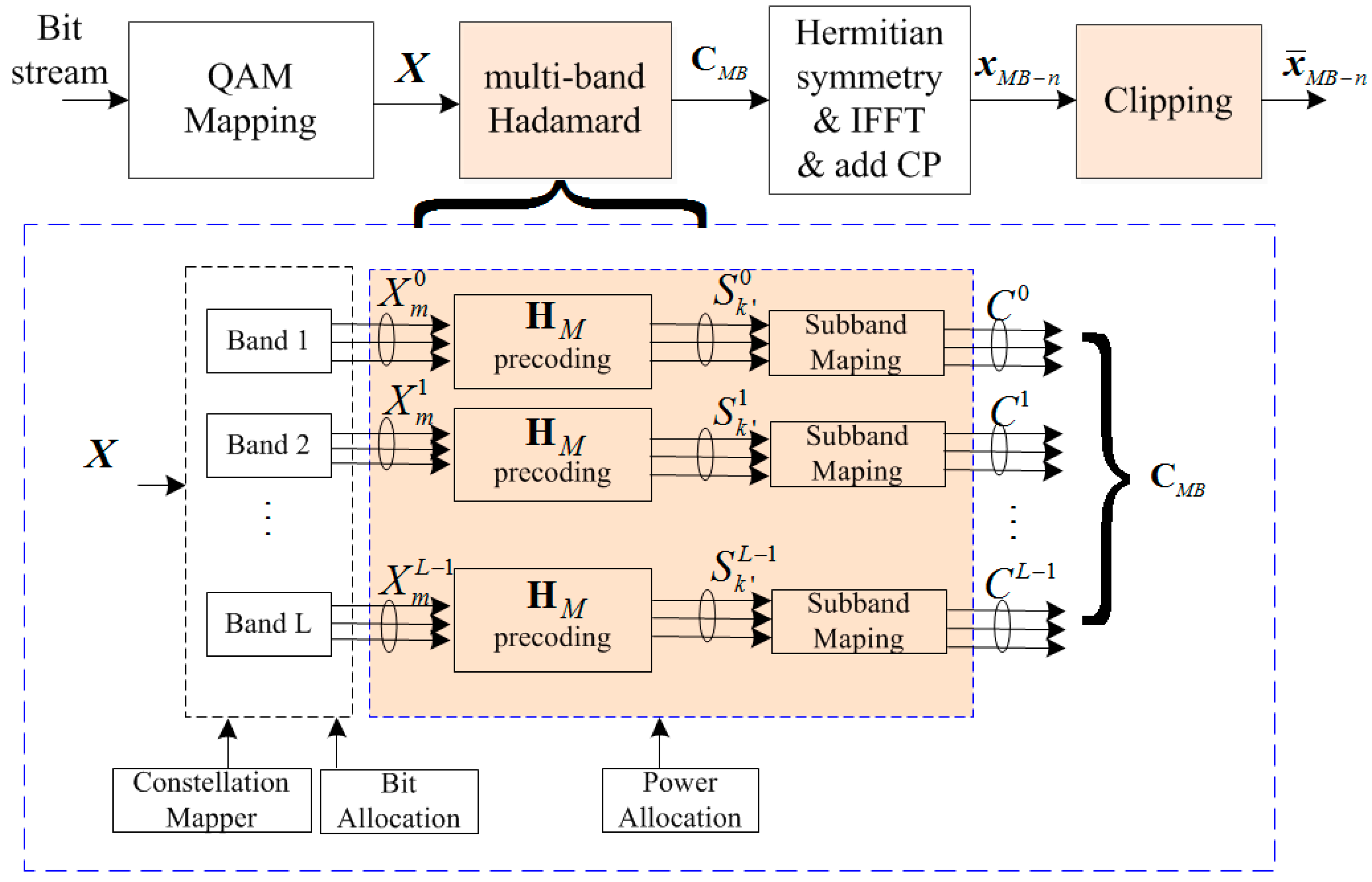
Figure 3.
Diagram of proposed decoding at receiver.
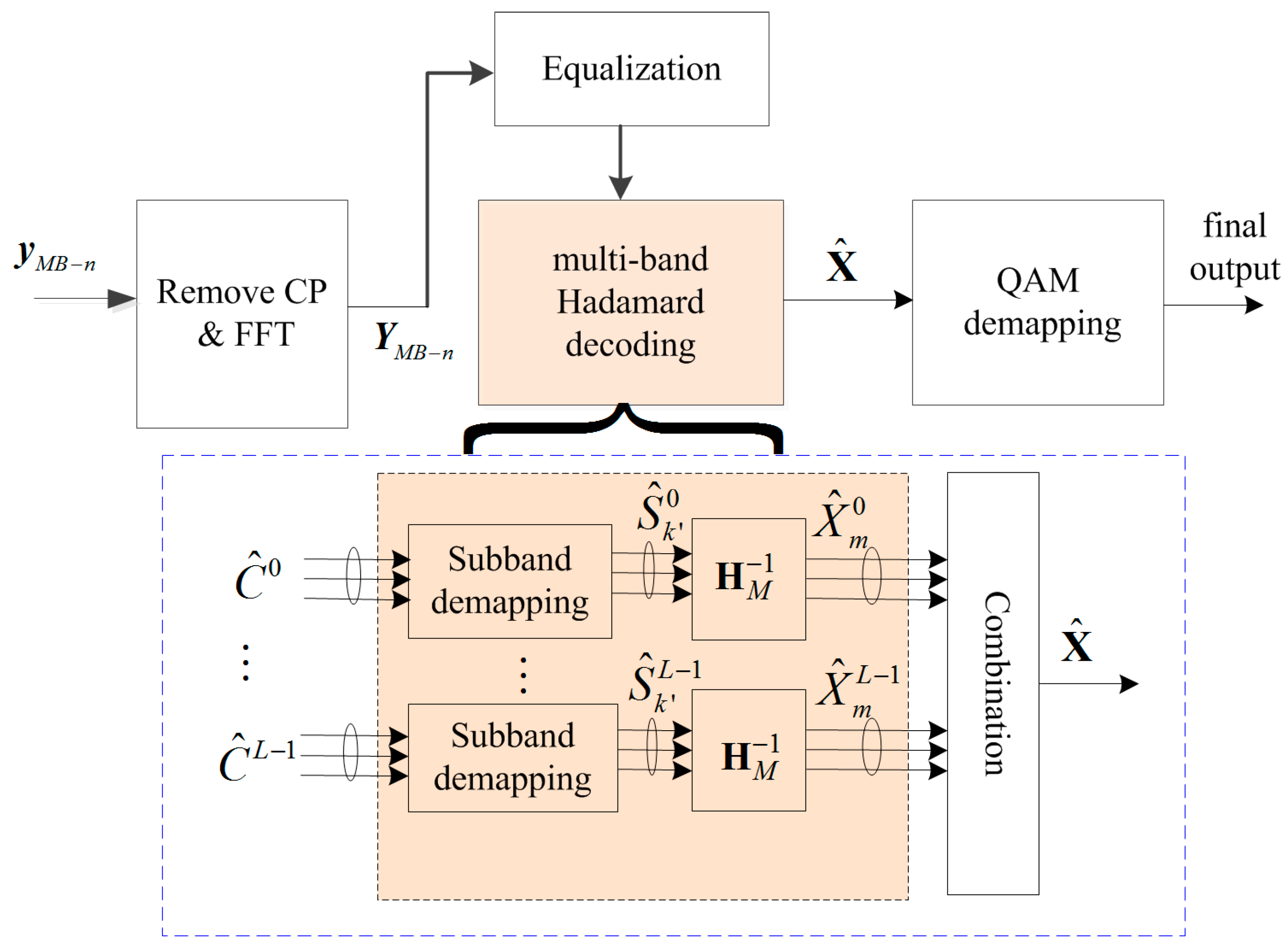
Figure 4.
Transmission setup with offline processing.

Figure 5.
Waveforms of proposed scheme with various numbers of split bands: (a) L = 1 (b) L = 4 (c) L = 8.
Figure 5.
Waveforms of proposed scheme with various numbers of split bands: (a) L = 1 (b) L = 4 (c) L = 8.
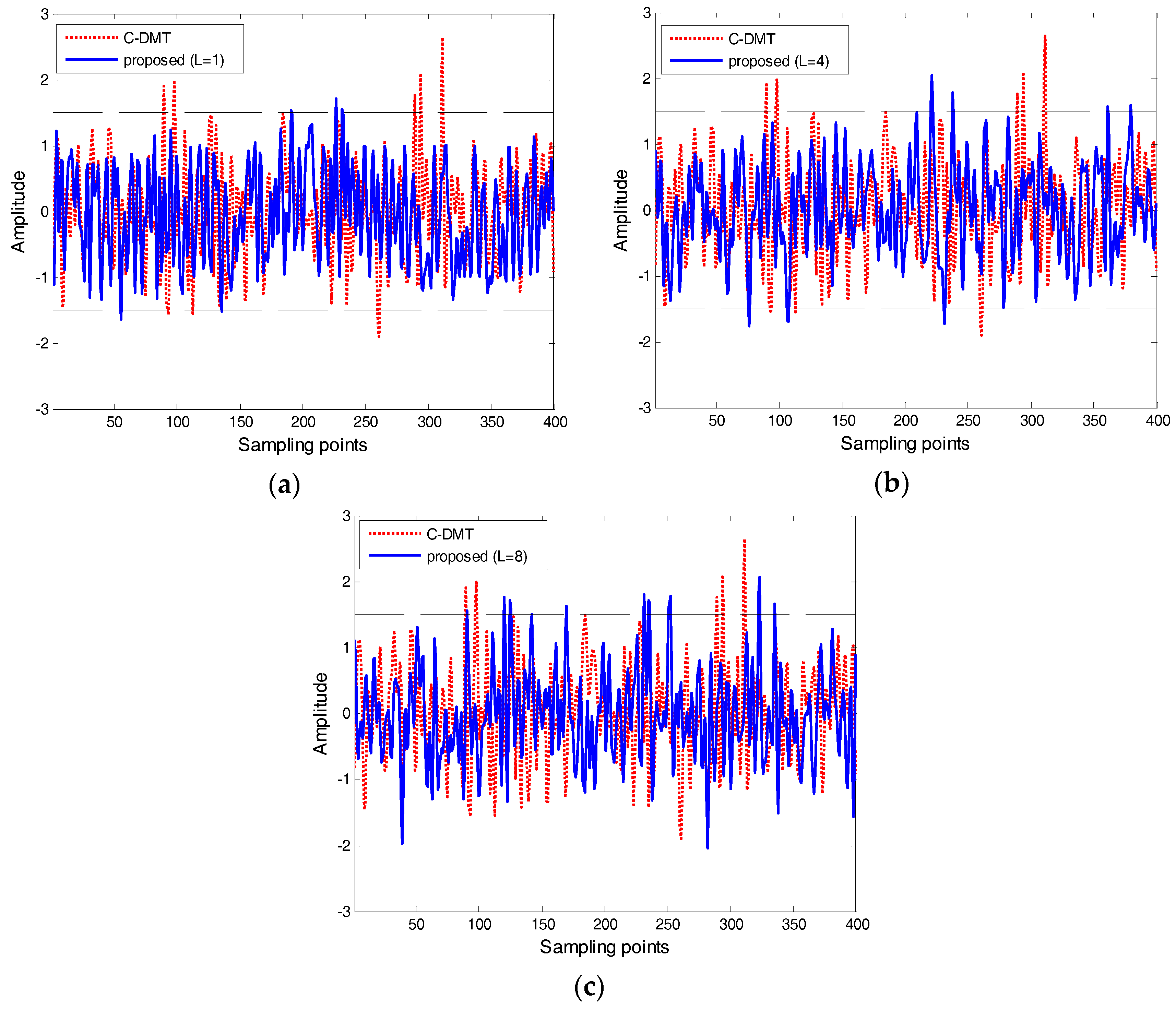
Figure 6.
Complementary cumulative distribution function (CCDF) performance comparison.

Figure 7.
CCDF performance comparison: (a) values for various subcarriers (b) probability density functions (PDFs) of aperiodic autocorrelation function (ACF) performance comparison (for 512 subcarrier with 4000 discrete multi-tone (DMT) symbols).
Figure 7.
CCDF performance comparison: (a) values for various subcarriers (b) probability density functions (PDFs) of aperiodic autocorrelation function (ACF) performance comparison (for 512 subcarrier with 4000 discrete multi-tone (DMT) symbols).
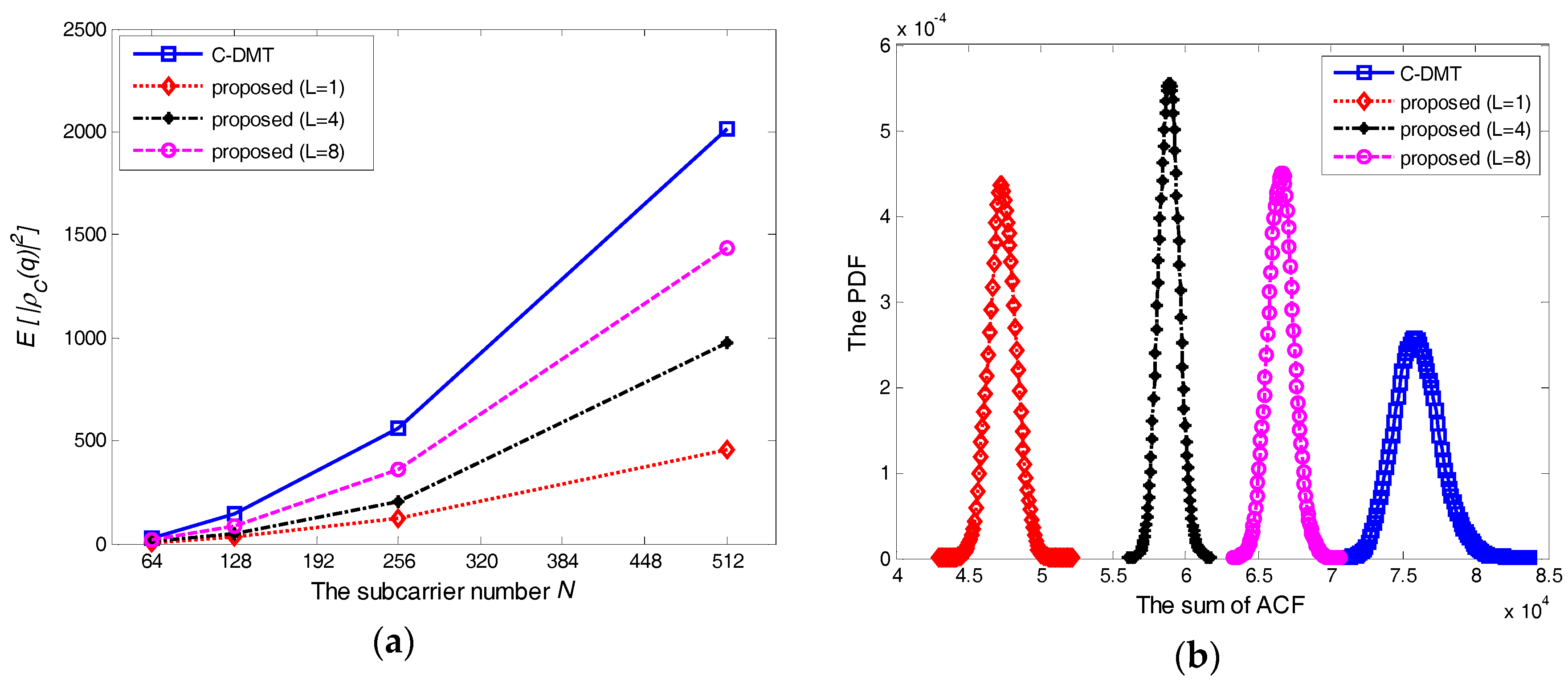
Figure 8.
Power spectral density (PSD) performance comparison.
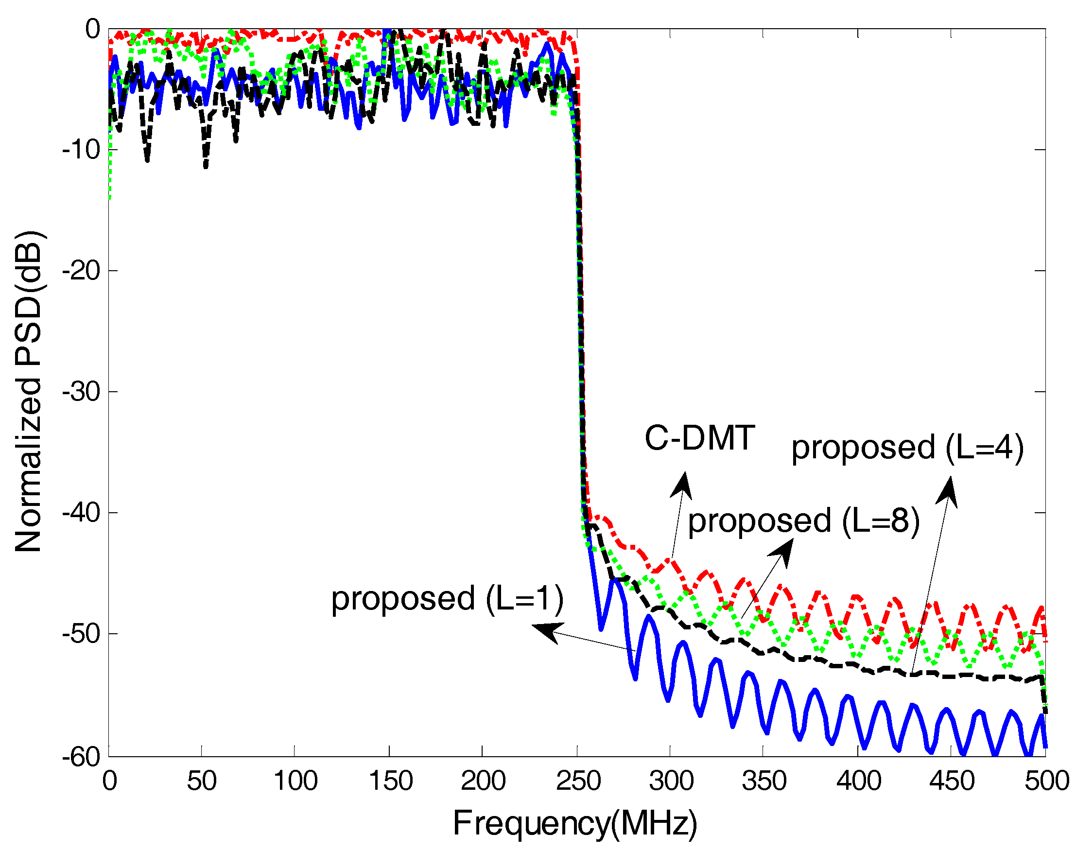
Figure 9.
Fifty-metre step index polymer optical fiber (SI-POF) transmission (a) Transmission rate (at a bit error rate (BER) of 10−3, without channel coding) (b) Bit and power distribution of the proposed scheme with L = 4 (for transmission rate of 1.204 Gbps) (c) The effective SNRs distribution.
Figure 9.
Fifty-metre step index polymer optical fiber (SI-POF) transmission (a) Transmission rate (at a bit error rate (BER) of 10−3, without channel coding) (b) Bit and power distribution of the proposed scheme with L = 4 (for transmission rate of 1.204 Gbps) (c) The effective SNRs distribution.
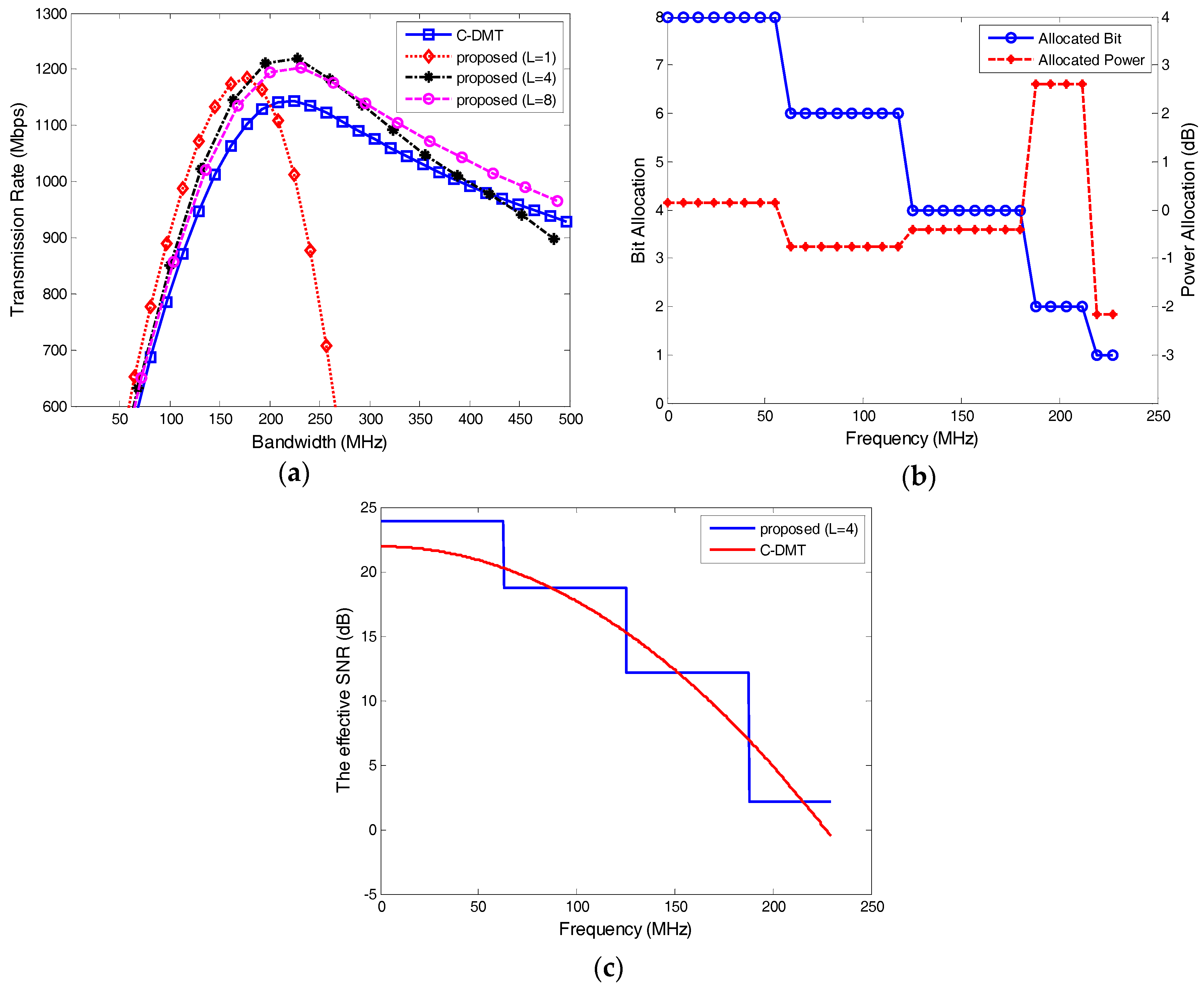
Figure 10.
Comparisons of BER performance.
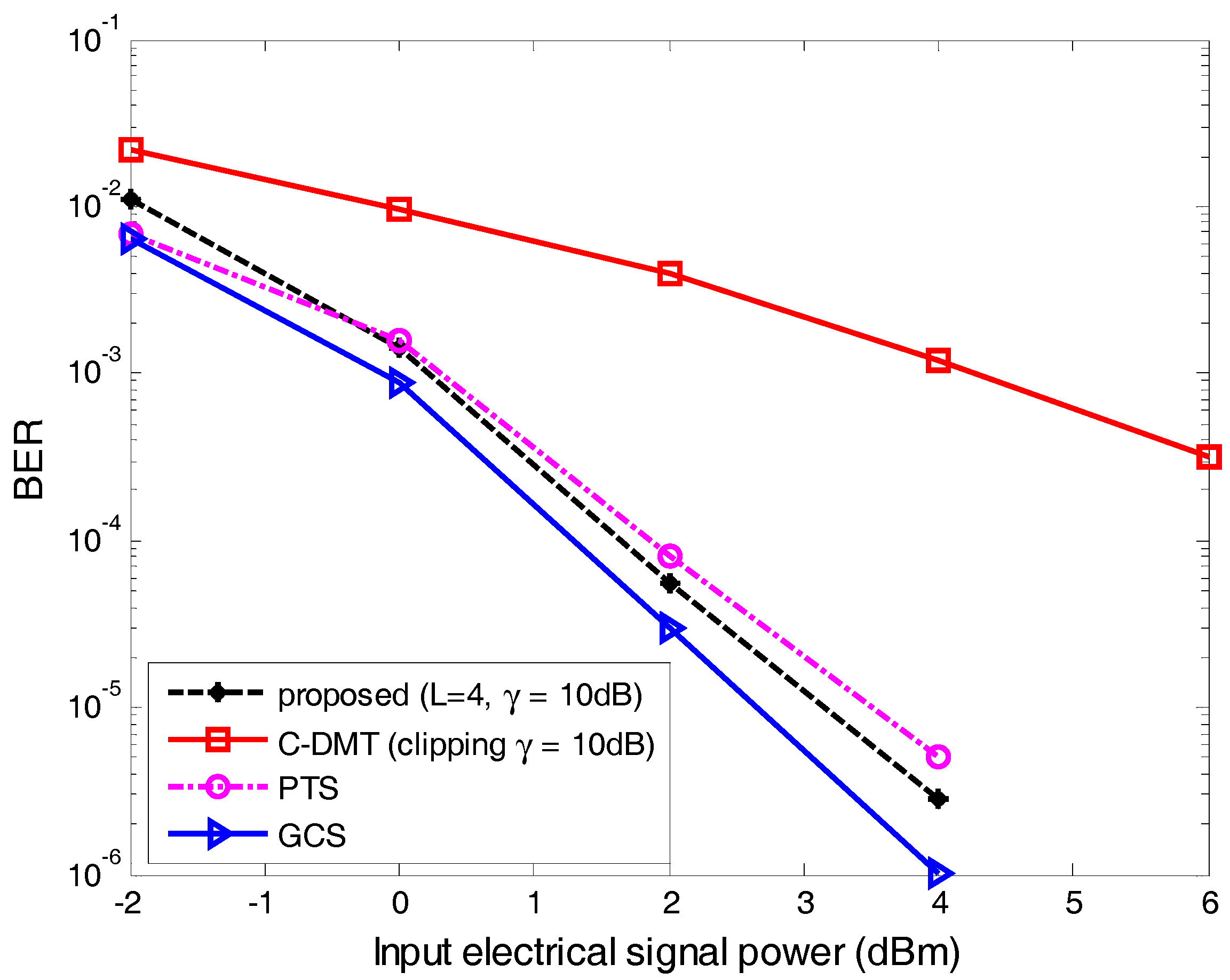
Figure 11.
Comparisons of computational complexity for different scheme.


Table 1.
Modulation parameters.
| DMT Parameter | Value |
|---|---|
| Sampling frequency (GHz) | 1.0 |
| IFFT/FFT length | 2048 |
| Subcarrier spacing (MHz) | 0.488 |
| Subcarrier number N | 1–1024 |
| Cyclic prefix ratio | 1/64 |
| Sub-band number L | 1, 4, 8 |
© 2018 by the authors. Licensee MDPI, Basel, Switzerland. This article is an open access article distributed under the terms and conditions of the Creative Commons Attribution (CC BY) license (http://creativecommons.org/licenses/by/4.0/).
Share and Cite
MDPI and ACS Style
Miao, P.; Chen, P.; Chen, Z. Low-Complexity PAPR Reduction Scheme Combining Multi-Band Hadamard Precoding and Clipping in OFDM-Based Optical Communications. Electronics 2018, 7, 11. https://doi.org/10.3390/electronics7020011
AMA Style
Miao P, Chen P, Chen Z. Low-Complexity PAPR Reduction Scheme Combining Multi-Band Hadamard Precoding and Clipping in OFDM-Based Optical Communications. Electronics. 2018; 7(2):11. https://doi.org/10.3390/electronics7020011
Chicago/Turabian StyleMiao, Pu, Peng Chen, and Zhimin Chen. 2018. "Low-Complexity PAPR Reduction Scheme Combining Multi-Band Hadamard Precoding and Clipping in OFDM-Based Optical Communications" Electronics 7, no. 2: 11. https://doi.org/10.3390/electronics7020011
Note that from the first issue of 2016, this journal uses article numbers instead of page numbers. See further details here.