Analyzing the Profile Effects of the Various Magnet Shapes in Axial Flux PM Motors by Means of 3D-FEA


Engineering Faculty, Electrical and Electronics Engineering, Erciyes University, 38039 Kayseri, Turkey
*
Author to whom correspondence should be addressed.
Electronics 2018, 7(2), 13; https://doi.org/10.3390/electronics7020013
Submission received: 14 December 2017
/
Revised: 22 January 2018
/
Accepted: 23 January 2018
/
Published: 25 January 2018
(This article belongs to the Special Issue Applications of Power Electronics)
Abstract
:Axial flux machines have positive sides on the power and torque density profile. However, the price of this profile is paid by the torque ripples and irregular magnetic flux density production. To gather higher efficiency, torque ripples should close to the zero and the stator side iron should be unsaturated. Torque ripples mainly occur due to the interaction between the rotor poles and the stator teeth. In this study, different rotor poles are investigated in contrast to stator magnetic flux density and the torque ripple effects. Since the components of the axial flux machines vary by the radius, analysis of the magnetic resources is more complicated. Thus, 3D-FEA (finite element analysis) is used to simulate the effects. The infrastructure of the characteristics which are obtained from the 3D-FEA analysis is built by the magnetic equivalent circuit (MAGEC) analysis to understand the relationships of the parameters. The principal goal of this research is a smoother distribution of the magnetic flux density and lower torque ripples. As the result, the implementations on the rotor poles have interesting influences on the torque ripple and flux density profiles. The MAGEC and 3D-FEA results validate each other. The torque ripple is reduced and the magnetic flux density is softened on AFPM irons. In conclusion, the proposed rotors have good impacts on the motor performance.
1. Introduction
Axial flux permanent magnet machines (AFPM) are one of the futuristic candidates for the higher performance aspiration. AFPM machines have high power/torque density, light mass/volume. It is applicable for many systems as researched in the literature. Mignot et al. designed an AFPM motor with magnetic equivalent circuit [1]. Kierstead et al. studied an in-wheel AFPM motor with non-overlapping windings [2]. Fei et al. researched an AFPM in-wheel motor with two air gap. They compared an approximation method with the 3D-FEA according to the calculation of the back EMF and cogging torque values [3]. Caricchi et al. suggested AFPM motors for direct-drive in-wheel applications with slotted windings. They considered the mitigation of the undesired effects, such as cogging torque and power loss due to flux pulsation in the core teeth, winding conductors, and rotor magnets [4]. Additionally, AFPM machines are investigated for many applications. Seo et al. studied robotic applications by using an analytic model and numeric analysis [5]. Parviainen et al. designed a generator in a small-scale wind-power applications [6]. Di Gerlando et al. focused on wind power generation after defining a general analysis of the model and design features of the AFPM machine [7]. De et al. proposed an ironless AFPM motor with low inductance for the aerospace industry in their paper [8]. One of the common points of these applications is sensitivity with the torque performance. Thus, torque ripples need to be as low as possible. Torque ripples mainly occur due to two main constituents, which are ripple torque and the cogging torque. The cogging torque is cultured by the mutual effects of the reluctance variation in stator and rotor magnetic flux. The ripple torque is mainly constituted by the coaction of the stator current magnetomotive force and rotor magnetic flux distribution in the surface permanent magnet (SPM) machines [9]. Both the cogging and ripple torques are related to rotor magnetic flux distribution, which is manipulated by shapes of PM in the SPM machines. In addition, the back EMF is one of the most crucial characteristics of the AFPM machine profile which is affected by the winding configurations as described by Saavedra et al. in [10].
Magnetic flux is the one basic characteristic of electric machines. There exist so many techniques to analyze the magnetic flux. One of the most prevailing methods is the MAGEC. Analyzing the magnetic flux by using MAGEC is one of the easiest analytical tools in comparison of the other methods given in the literature. Since magnetic flux paths simply turn into the circuit components and the problem is solved by the circuit analysis easily [11,12,13,14]. If the solution of the MAGEC is done, air gap magnetic flux density, permanent magnet axial length, the total permeance of the machine, back EMF value, winding resistance, self-inductance, and torque and output power can be composed according to the study of Mignot et al. [1]. The stator winding resistance, eddy current resistance, end winding resistance, power factor, phase voltages, output power, and steady-state torque are counted by the MAGEC perusal in the research of Wang et al. [15]. Parviainen et al. [11], Tiegna et al. [12], Bellara et al. [13], and Lubin et al. [14], mentioned different analytical calculation techniques for analyzing the characteristics of the AFPM machine in the literature.
In the literature, various topologies were investigated to reduce torque ripple including the shaping of rotor magnet pole and stator slots. Aydin et al. studied the shaping of rotor magnet pole which was realized by skewing or displacing magnet poles [16]. Sung et al. proposed the shaping of stator slots by recasting slot or teeth numbers in [17]. Saavedra et al. researched the effects of the magnet shaping under demagnetization fault conditions by means of 3D-FEA. The research aimed to determine a more efficient magnet geometry [18]. Kahourzade et al. summarized the torque ripple reducing methods by means of the classification of the AFPM machines [19].
This paper suggests analyzing the three-phase single air gap AFPM machine as given in Figure 1 by means of the 3D-FEA analysis. Five different rotor designs are investigated to achieve the goals. The first goal is to use MAGEC to observe the magnetic flux path and to describe the magnetic events in an analytic way. Another goal is to investigate the torque ripple, back EMF, and air gap magnetic flux distribution results of the proposed rotors in 3D-FEA. Two of the five designs are the novel magnet shapes, which are mainly developed for mitigating the torque ripples. The proposal is stepping and shifting the rotor magnets. Due to this action affects the magnetic flux path, back EMF, and torque waveforms are changed. All of the designs are simulated in 3D-FEA to compare the novel topologies and exciting results are obtained.
2. MAGEC Design and Analysis
MAGEC design is composed of the magnetic flux path at the machine given in Figure 2. Each definition of the flux sources and the permeance are situated by considering this path. The describing of the elements of MAGEC eases the analytical solutions by obtaining the parameters easily.
An interesting specialty of the AFPM machine is that most of the parameters vary by the radius. The produced torque is defined by the radius, too. Due to this, the MAGEC is designed by considering the single air gap AFPM motor in this section. Conceptual 2D and 3D representations are seen in Figure 2.
The rotor and the stator back irons are produced from ferromagnetic steel, and these steels are designed from layers, like round strips, which are laminated in the circumference direction. Permanent magnets are placed on the surface of the rotor back iron. There are gaps between each pole to minimize the permanent magnet flux leakage. As seen from Figure 2, flux paths are the same for each permanent magnet pole. Since the flux divides by two for each pole, just one closed loop is modeled in the MAGEC Equations.
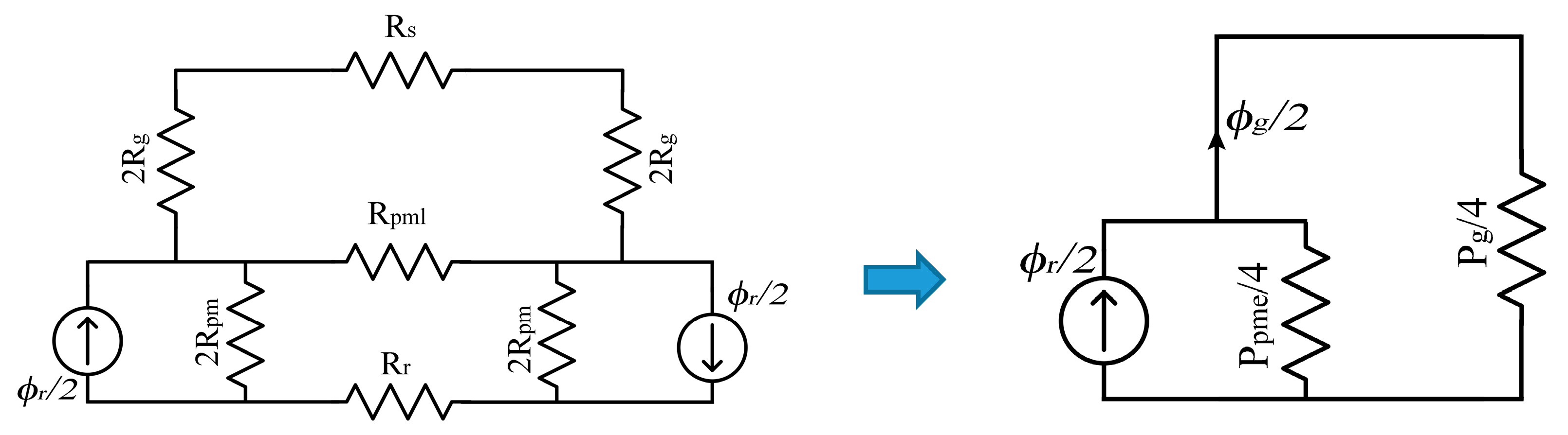
The developed MAGEC is shown in Figure 3, which is designed by minding the flux path illustrated in Figure 2a,b. The two permanent magnet halves, rotor and stator back iron, air gap, and the gap between poles are included in the MAGEC.
Three stator teeth per one pole are determined for the studied single air gap AFPM motor, as demonstrated in Figure 2. Thus, the stator has 24 teeth and the rotor has eight magnets. Other parameters are listed in Table 1.
Since air gap permeability μ0 is much lower than iron permeability, the air gap reluctance is much higher than the rotor and stator back iron reluctances. Due to this, the rotor and stator reluctances can be neglected to have an easier solution. Thus, the MAGEC can be simplified, as in Figure 4. In the end, the permeance values are taken into account instead of the reluctances.
The simplified MAGEC is located to the 2D design of the AFPM machine as given in Figure 5. The relationship between the air gap flux and the rotor flux is pointed out in the Equation (1).
where Ppme is the effective permanent magnet permeance, and Pg is the air gap permeance.
Permanent magnet and steel data are given in Table 2. Additionally, permeance of the magnet is defined in Equation (2):
Here, LPM is the permanent magnet’s height and the APM is the surface area of the permanent magnet. The height of the permanent magnet can be determined by Equation (3) [20]:
The permanent magnet surface area is calculated in contrast to the inner and outer radii, as given by Equation (4):
Here, Npm is the number of the pole of the AFPM machine. The pole area Ap is necessary to find the magnet fill factor αpm:
A magnetic flux leakage occurs between the adjacent magnets on the rotor. The path of this flux leakage draws an arc between two magnets. When this path is accounted, the obtained leakage permeance is calculated by Equation (7). Ppml is the permeance of the gap between the two adjacent permanent magnets. If the simplification of the MAGEC is taken into account by applying Ppme = Ppm + 4Ppml, Equation (8) can be derived to simplify the equation by a coefficient (Kpml) which is given in Equation (9). The effective permanent magnet permeance (Ppme) is defined by the multiplication of the permanent magnet permeance Ppm and Kpml in Equation (8):
Equations (7)–(9) allows simplifying the MAGEC, as seen in Figure 4. In addition, air gap permeance can be calculated correctly by defining the effective air gap ge = Kcg, and the air gap area [21]. Thus, the interaction between the air gap flux and the rotor flux becomes as specified in Equation (11):
One of the main subjects to create the MAGEC is the defining the air gap magnetic flux density. In the light of the Equation (11), the magnetic flux density Bg can be calculated as stated in the Equation (12) where Kkϕ = Apm/Ag and Cp = LPM/gKkϕ:
As given in Equation (13), permanent magnet flux produces the air gap flux density and results in the voltage induction, called back EMF, in the stator windings. This can be seen from the MAGEC depicted in Figure 4.
The force Equation (15) is composed of the electric-magnetic loads from Equation (14) and the total area of the magnets from Equation (4). If these Equations are applied from the inner to the outer radius, the electromagnetic torque equation becomes that shown by Equation (16):
Here, Jin, is the current density at the inner radius Di, and λ is the rate of the radiuses which is counted by Di/Do.
3. Analyzed Rotor Pole Designs
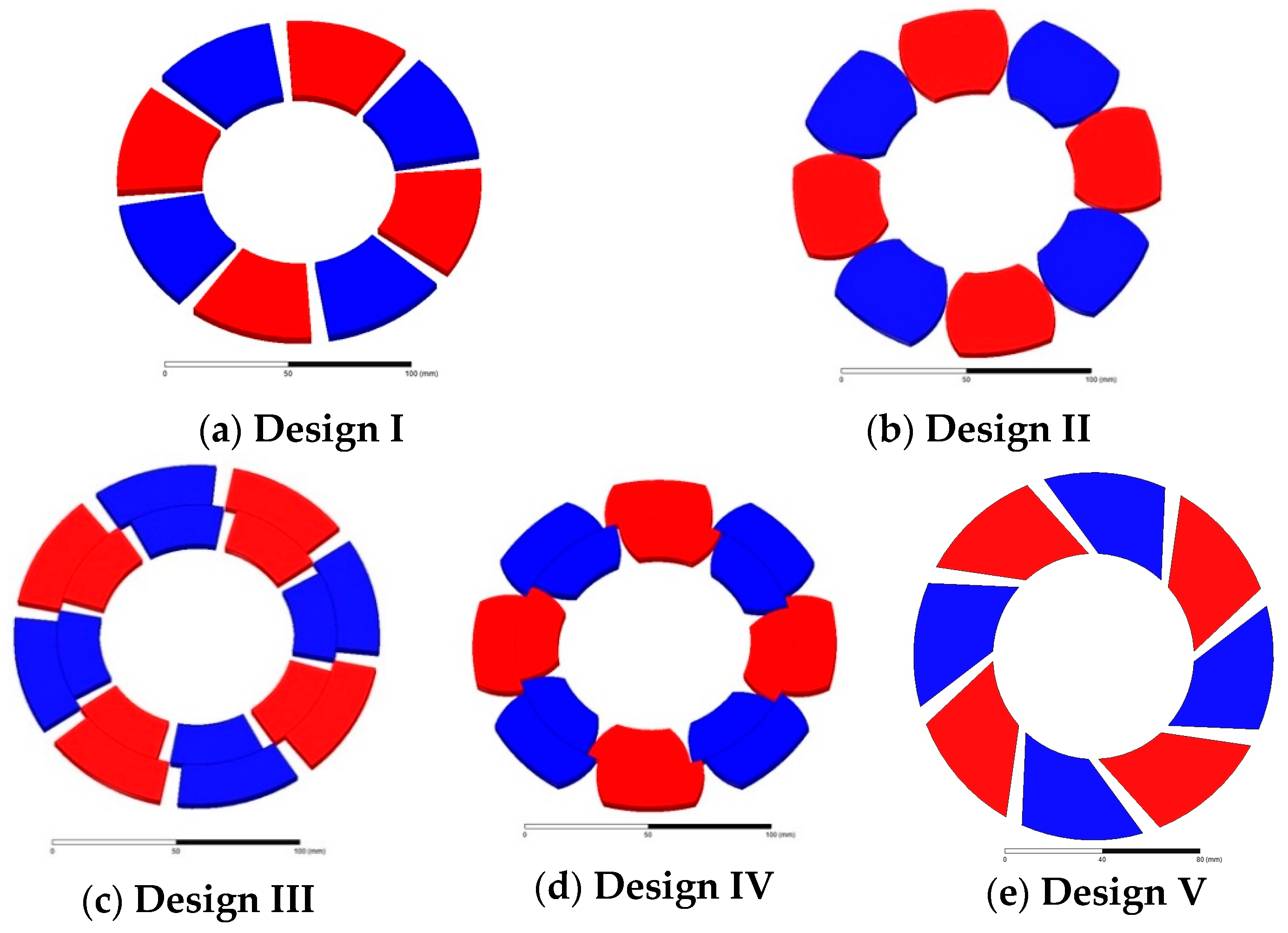
The single air gap, slotted AFPM motor is taken into account as the reference design structure, which is demonstrated in Figure 1. The studied motor parameters are given in Table 1. Five different rotor pole designs are investigated in this research. Design I is a conventional rotor pole design of an AFPM machine model, taken as the reference model for this study, which can be seen in Figure 6a. It has sharp edges. This type of magnet can be easily found on the market. Design II is an improved rotor pole model for an AFPM machines, as seen in Figure 6b. It has sinusoidal edges. This design is studied to reduce the cogging torque in the literature [22]. Design III is one of the proposed rotor pole models for this research, and is shown in Figure 6c. This design is the novel proposal for AFPM motors. It is studied to reduce the torque ripples. Design IV is another proposed rotor model for this research, as seen in Figure 6d. This design is a novel proposal for axial flux machines. Design V is developed for validating the FEA model. Aydin and Gulec proposed that cogging torque has minimum values when skewing angle is 18.75°, such as that used in this study for design V, given in Figure 6e. The FEA simulation of designs I and V prove the validation of the FEA model in comparison with [23].
All of the permanent magnet poles are magnetized in the z-axis and the total value of the inner and outer diameters are the same for each pole designs. The MAGECs of each design do not change in majority due to the constant magnet fill factor αpm, which is 0.8722 for each design. Additionally, all permanent magnet pole designs have symmetry in the radial direction.
4. 3D-FEA Analysis
The back EMF, torque, and flux density distribution waveforms are obtained from the three-dimensional finite element analysis. Both transient and static analyses are performed. 3D-FEA simulations are performed for the ¼ of the AFPM motor designs, as given in Figure 7, in order to shorten the simulation time. A runtime process of 10 milliseconds is chosen, thus, the motor turns more than one time during the simulation. M250-35A steel and NdFe magnet specifications are given in Table 2. The values are defined in 3D-FEA. Additionally, the cylindrical coordinate system is used to define the axial flux steel orientation.
Before starting the comparison of five designs, the optimum shifting angles of the suggested rotor poles must be specified. The shifting angle means that inner rotor step magnets are displaced by an angle from the outer rotor magnets, as seen in Figure 6c,d. One of the aims of this shifting method is the mitigation of the torque ripples. There are some analytical methods to define the best shift angle in the literature. One of them is the cogging torque period method that is described in [11], but this method does not give the best results for the AFPM machines. In this research, parametric analysis with 3-D FEA is used to find the optimum shifting angle.
The shifting angle is defined as a variable and differs from 0° to 14° by 1° steps. The third magnet design is used to perform this analysis. The average torque and the torque ripple values are taken into account for each result in order to mitigate the total torque ripples. Figure 8 demonstrates the results of the parametric analysis. Table 3 shows each peak-to-peak torque ripple and the average torque value for each shifting angle.
The simulations gave interesting results from the total parametric analysis. If the torque ripple is the most important anchor of the application, the best result is the 11° shifting angle which gives 2.16 N·m. of peak-to-peak cogging torque. However, if the average torque value is the most valued parameter, the 3° shifting angle has the highest average torque of 51.27 N·m., which is 1.3 N·m. higher than the 0° shifting angle. Torque ripple drops from a shifting angle of 1° to 11°, but after 11° it starts to rise again.
After defining the shifting angle of the third and fourth designs, the magnetic simulations are completed for each design in both static and dynamic conditions. The stator was split into four identical parts and one of them was investigated due to the symmetrical geometry to reduce the simulation time.
5. Comparison of the Results of the Proposed Designs
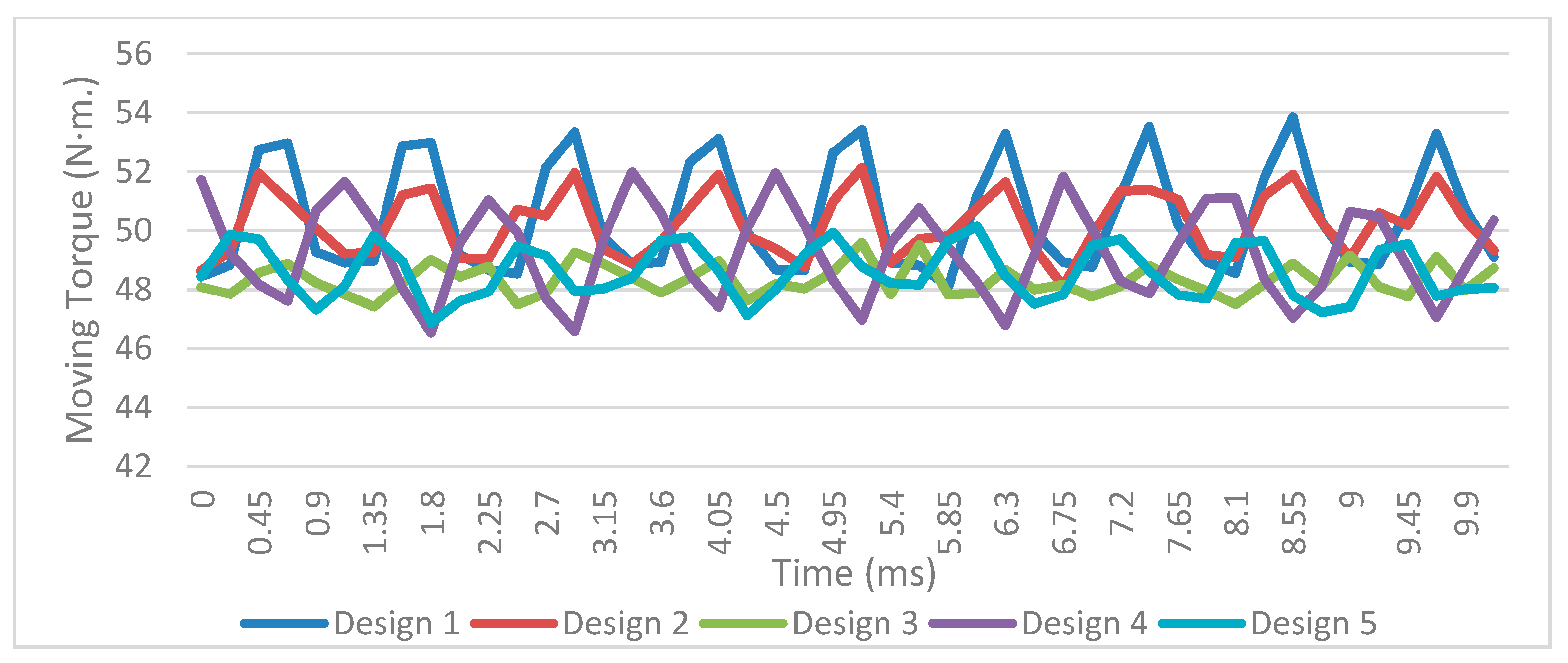
In the 3D-FEA analysis, PMs have an 11° shifting angle in designs III and IV due to the seeking of the lowest torque ripple. Torque and back EMF waveforms are taken from the dynamic simulations. Figure 9 illustrates the electromagnetic torque results of the five designs that are shown in Figure 6. As seen from the torque results, the lowest torque ripple is in the third design, with 62.4% mitigation, despite a 4.3% reduction on the average torque compared to the design I. The table of the comparison is demonstrated in Table 4. Although it has step and shift on the magnets, design IV has some of the worst data in the view of the torque ripple in this study. This is because of the magnet edges. Since some arrays are sinusoidal, some arrays are sharp. Thus, magnetic flux distribution is unsteady. Additionally, design V has a 43.2% reduction in torque ripple with a 0.8722 magnet fill factor (pole-arc ratio), as validated by Aydin and Gulec, although with some different characteristics of the simulated motors, like magnet thickness, air gap, and the dimensions in [23]. As seen from the simulations, the skewing process has a lower reduction effect than the stepping and shifting process effect on the torque ripple, as demonstrated in Table 4.
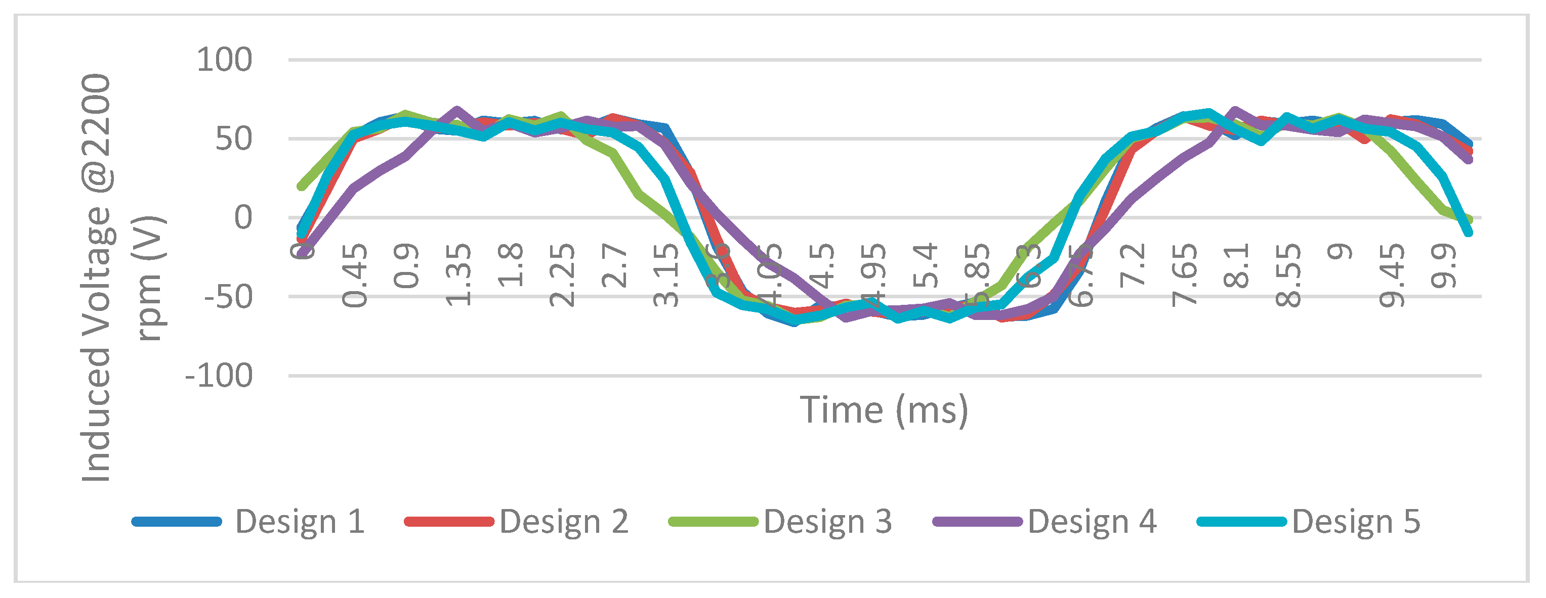
Back EMF depends directly on the speed, number of turns, pole numbers, inner and outer radii, and the magnetic flux density, as given in the Equation (13). All of these parameters are stationary without the magnetic flux density in this study. Magnetic flux density depends on the permanent magnet magnetic flux. The average values of the parameters are given in Table 5. Analytical results are obtained by calculating the MAGEC Equations (12), (13), and (16) developed earlier. The constant values are given in Table 6. Figure 10 illustrates the back electromotive force waveforms of each design. The smoothness of these waveforms is crucial to have more constant torque. That means lower torque ripple. Hence, design III has smoother back EMF and lower torque ripple waveforms.
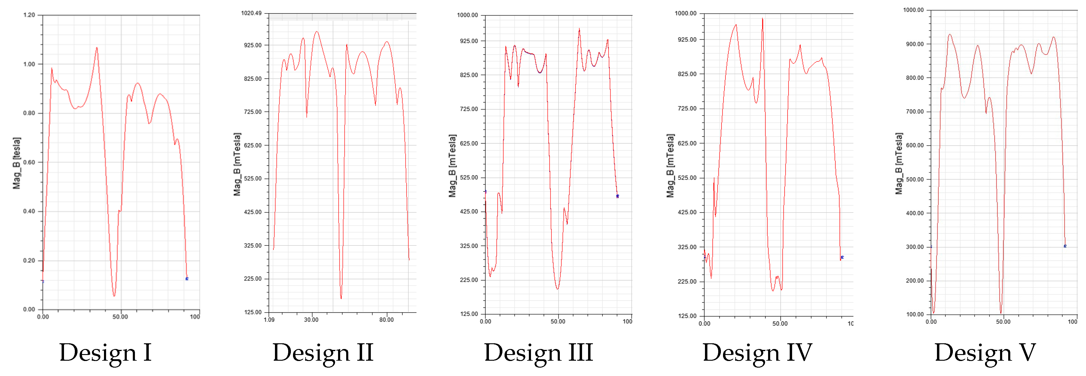
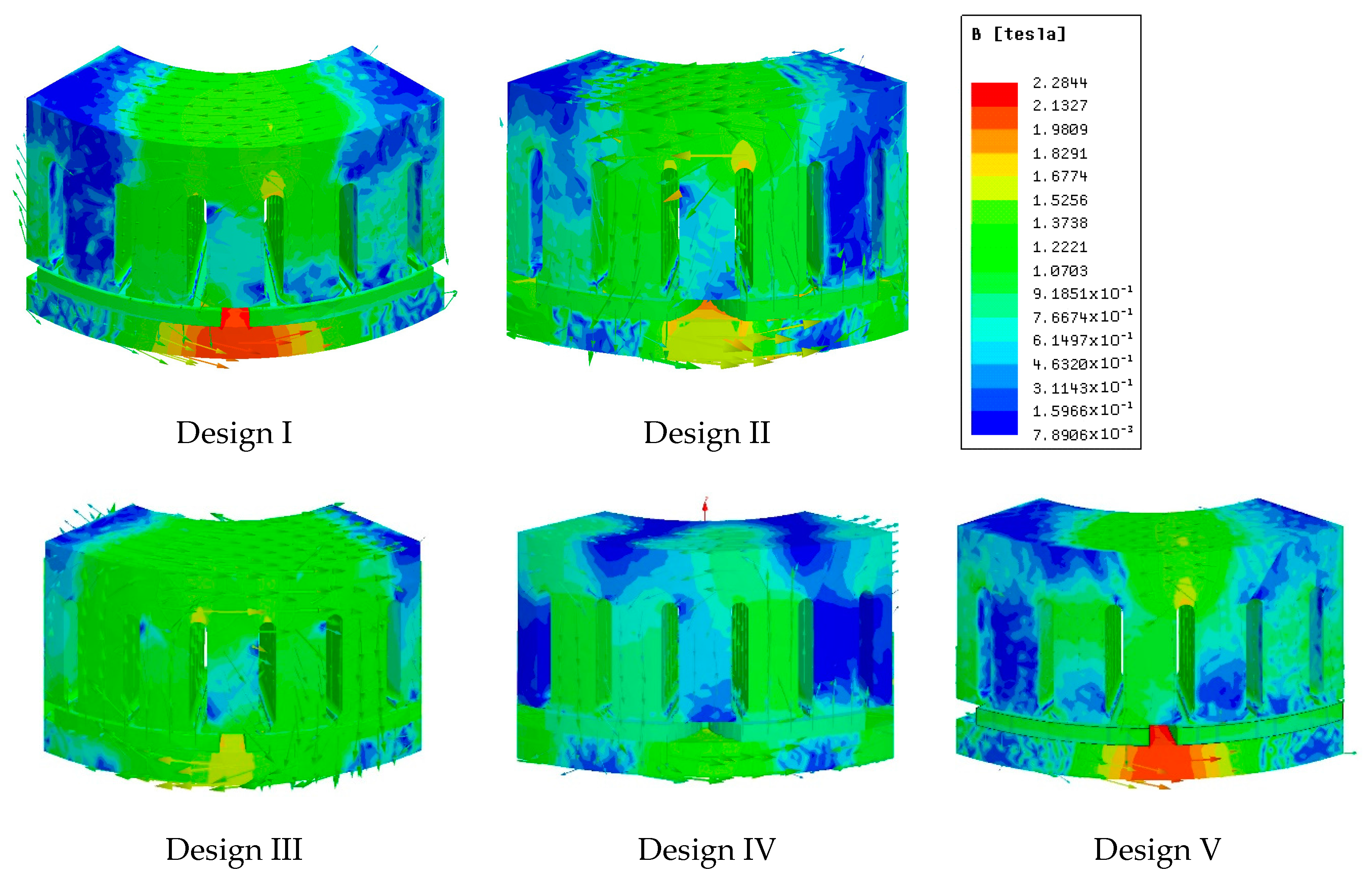
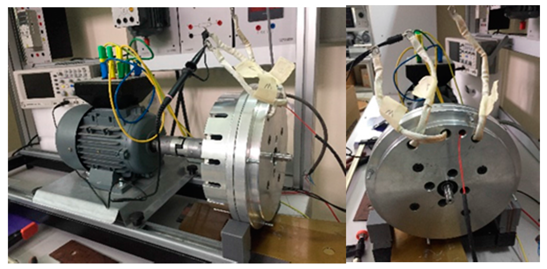
The flux density distributions are given in Figure 11 for five designs which demonstrate the radial components of the flux density between the magnets and the stator steel. Since the simulations are conducted for ¼ of the motor, the waveforms are produced in 90 degrees. The simulation has interesting results that have caused by the proposed rotor pole designs. The rotor permanent magnet flux does not drop under 0.2 T in designs III and IV, unlike designs I, II, and V. The geometry of the proposition provides these conclusions. Figure 12 shows the magnetic flux densities on the surfaces of the AFPM motor. The first and fifth designs have too high a magnetic flux leakage between the magnets, as seen in Figure 12. The high magnetic flux causes the saturation of the iron. Saturation is an undesired situation which may cause heat and unsteady inductance. Stepping and shifting of magnets allow resistance to the leakage flux. Designs I and V have strong magnetic saturation between the adjacent magnets due to the magnet shapes. Constant width and straight edges of the adjacent magnets ease the magnetic flux leakage. Due to the sinusoidal shape, design II has a lower magnetic saturation than designs I and V. Figure 13 shows the prototype of the AFPM machine.
6. Conclusions
Different rotor pole designs are investigated in this study by means of the MAGEC and FEA analyses. The MAGEC gives the understanding of the single air gap AFPM machine and FEA analyzes the characteristics of the AFPM machine. The MAGEC describes the infrastructure of the AFPM machine characteristics that are obtained from the 3D-FEA. The magnetic flux paths are illustrated by the MAGEC in Figure 2, Figure 3, Figure 4 and Figure 5. Table 4 compares the results of the electromagnetic torque and torque ripples for all magnet shapes. TR/AT values prove that design III has the lowest rate and, hence, an average torque reduction of 4.3%. Transient analysis is performed by 3D-FEA for 10 milliseconds. Each design is discussed in contrast to the simulation results. Additionally, a parametric analysis is fulfilled to determine the best solution for the shifting angle. The electromagnetic torque and the back EMF waveforms are demonstrated in Figure 9 and Figure 10, which are obtained from the transient analysis. Table 5 is demonstrated to prove the methods. The MAGEC and 3D-FEA results are compared in Table 5 in terms of air gap magnetic flux density, back EMF, and torque characteristics. The 3D-FEA and MAGEC results validate each other.
Furthermore, the magnetic flux density distribution waveforms are given in Figure 11 and the surface magnetic flux density profiles are given in Figure 12. The air gap magnetic flux density is not collapsed under 0.2 T by the permanent magnets in designs III and IV, unlike design numbers I, II, and V. However, Figure 12 gives information for the saturation of the irons. Design I and V have strong flux leakage between the adjacent magnets, but the saturation points are mostly in the rotor iron, hence, the results are not affected much at the 3D-FEA simulation time as given in the Table 5. Additionally, the MAGEC results do not contain saturation effects. Thus, the heat effects are neglected in the 3D-FEA results in Table 5. If the permanent magnets are damaged by the heat caused by the saturation, all characteristics in Table 5 could be changed dramatically. Resultantly, the third design has the best results in contrast to the precision on the stability of moving torque. Additionally, the results show that stepping and shifting method has better results compared with the skewing method in the view of torque ripple mitigation. The magnets will be produced privately for designs III and IV. Hence, the costs may be higher for the prototype, but the magnet costs of each design will be the same for mass production since the magnet weights being the same. Moreover, a prototype machine can be seen in Figure 13 which is manufactured in the light of this paper for further studies.
Acknowledgments
This study researched by the supports of the TUBITAK (The Scientific and Technical Research Council of Turkey), and WEMPEC. (Wisconsin Electric Machines and Power Electronics Concorsium).
Author Contributions
E.C. and F.D. conceived and designed the MAGEC and 3D-FEA; E.C. performed the simulations; E.C. and F.D. analyzed the data; E.C. wrote the paper.
Conflicts of Interest
The authors declare no conflict of interest.
Nomenclature
| Rs | The reluctance of the stator back iron, |
| Rr | The reluctance of the rotor back iron, |
| Rg | The reluctance of the air gap between the stator and the rotor, |
| Rpm | The reluctance of the permanent magnet, |
| Rpml | The reluctance of the air gap between the two permanent magnets, |
| ϕr | Magnetic flux flows from the rotor pole, |
| ϕg | Flux flow passed from the air gap into the stator |
| Ppm | The permeance of the permanent magnet |
| Ppml | The permeance of the gap between adjacent magnets |
| Kc | Carter’s coefficient |
| Kf | The correction factor of the air gap magnetic flux density in radial direction |
| Kd | Flux leakage coefficient |
| Kpml | Leakage coefficient between the magnets |
| Kkϕ | Flux density coefficient |
| df | The distance between adjacent magnets |
| Npm | Number of the magnets |
| Ap | Area of a pole |
| Cp | Permeance factor |
| Nw | Number of turns |
| Jin | Current density |
| Ns | Slot number |
References
- Mignot, R.B.; Dubas, F.; Espanet, C.; Chamagne, D. Design of Axial Flux PM Motor for Electric Vehicle via a Magnetic Equivalent Circuit. In Proceedings of the First International Conference on REVET-2012 Renewable Energies and Vehicular Technology, Hammamet, Tunisia, 26–28 March 2012; pp. 212–217. [Google Scholar]
- Kierstead, H.; Wang, R.; Kamper, M. Design optimization of a single sided axial flux permanent magnet in-wheel motor with non-overlap concentrated winding. In Proceedings of the 18th Southern African Universities Power Engineering Conference, Stellenbosch, South Africa, 28–29 January 2009; pp. 36–40. [Google Scholar]
- Fei, W.; Luk, P.; Jinupun, K. A new axial flux permanent magnet segmented-armature-torus machine for in-wheel direct drive applications. In Proceedings of the Power Electronics Specialists Conference, Rhodes, Greece, 15–19 June 2008; pp. 2197–2202. [Google Scholar]
- Caricchi, F.; Capponi, F.G.; Crescimbini, F.; Solero, L. Experimental study on reducing cogging torque and no-load power loss in axial-flux permanent-magnet machines with slotted winding. IEEE Trans. Ind. Appl. 2004, 40, 1066–1075. [Google Scholar] [CrossRef]
- Seo, J.M.; Rhyu, S.; Kim, J.; Choi, J.; Jung, I. Design of Axial Flux Permanent Magnet Brushless DC Motor for Robot Joint Module. In Proceedings of the IEEE International Power Electronics Conference, Sapporo, Japan, 21–24 June 2010; pp. 1336–1340. [Google Scholar]
- Parviainen, A.; Pyrhönen, J.; Kontkanen, P. Axial flux permanent magnet generator with concentrated winding for small wind power applications. In Proceedings of the IEEE International Conference on Electric Machines and Drives, San Antonio, TX, USA, 15 May 2005; pp. 1187–1191. [Google Scholar]
- Di Gerlando, A.; Foglia, G.; Iacchetti, M.F.; Perini, R. Axial flux pm machines with concentrated armature windings: Design analysis and test validation of wind energy generators. IEEE Trans. Ind. Electron. 2011, 58, 3795–3805. [Google Scholar] [CrossRef]
- De, S.; Rajne, M.; Poosapati, S.; Patel, C.; Gopakumar, K. Low inductance axial flux BLDC motor drive for more electric aircraft. IET Power Electron. 2012, 5, 124–133. [Google Scholar] [CrossRef]
- Jahns, T.M.; Soong, W.L. Pulsating torque minimization techniques for permanent magnet ac motor drives—A review. IEEE Trans. Ind. Electron. 1996, 43, 321–330. [Google Scholar] [CrossRef]
- Saavedra, H.; Urresty, J.-C.; Riba, J.-R.; Romeral, L. Detection of interturn faults in PMSMs with different winding configurations. Energy Convers. Manag. 2014, 79, 534–542. [Google Scholar] [CrossRef]
- Parviainen, A.; Niemela, M.; Pyrhonen, J. Modeling of axial flux permanent-magnet machines. IEEE Trans. Ind. Appl. 2004, 40, 1333–1340. [Google Scholar] [CrossRef]
- Tiegna, H.; Bellara, A.; Amara, Y.; Barakat, G. Analytical modeling of the open-circuit magnetic field in axial flux permanent-magnet machines with semi-closed slots. IEEE Trans. Magn. 2012, 48, 1212–1226. [Google Scholar] [CrossRef]
- Bellara, A.; Amara, Y.; Barakat, G.; Dakyo, B. Two-dimensional exact analytical solution of armature reaction field in slotted surface mounted pm radial flux synchronous machines. IEEE Trans. Magn. 2009, 45, 4534–4538. [Google Scholar] [CrossRef]
- Lubin, T.; Mezani, S.; Rezzoug, A. 2-d exact analytical model for surface-mounted permanent-magnet motors with semi-closed slots. IEEE Trans. Magn. 2011, 47, 479–492. [Google Scholar] [CrossRef]
- Wang, R.J.; Kamper, M.J.; Westhuizen, K.V.; Gieras, J.F. Optimal Design of a Coreless stator Axial Flux Permanent Magnet Generator. IEEE Trans. Magn. 2005, 41, 55–64. [Google Scholar] [CrossRef]
- Aydin, M.; Zhu, Z.Q.; Lipo, T.A.; Howe, D. Minimization of Cogging Torque in Axial-Flux Permanent-Magnet Machines: Design Concepts. IEEE Trans. Magn. 2007, 43, 3614–3622. [Google Scholar] [CrossRef]
- Sung, S.J.; Park, S.J.; Jang, G.H. Cogging torque of brushless DC motors due to the interaction between the uneven magnetization of a permanent magnet and teeth curvature. IEEE Trans. Magn. 2011, 47, 1923–1928. [Google Scholar] [CrossRef]
- Saavedra, H.; Riba, J.-R.; Romeral, L. Magnet shape influence on the performance of AFPMM with demagnetization. In Proceedings of the 39th Annual Conference of the IEEE Industrial Electronics Society, Vienna, Austria, 10–13 November 2013; pp. 973–977. [Google Scholar]
- Kahourzade, S.; Mahmoudi, A.; Ping, H.W.; Uddin, M.N. A Comprehensive Review of Axial-Flux Permanent-Magnet Machines. Can. J. Electr. Comput. Eng. 2014, 37, 19–33. [Google Scholar] [CrossRef]
- Mahmoudi, A.; Kahourzade, S.; Abd Rahim, N.; Hew, W.P. Design, Analysis, and Prototyping of an Axial-Flux Permanent Magnet Motor Based on Genetic Algorithm and Finite-Element Analysis. IEEE Trans. Magn. 2013, 49, 1479–1492. [Google Scholar] [CrossRef]
- Qishan, G.; Hongzhan, G. Effect of Slotting in PM Electric Machines. Electr. Mach. Power Syst. 1985, 10, 273–284. [Google Scholar] [CrossRef]
- Shokri, M.; Rostami, N.; Behjat, V.; Pyrhönen, J.; Rostami, M. Comparison of performance characteristics of axial-flux permanent-magnet synchronous machine with different magnet shapes. IEEE Trans. Magn. 2015, 51. [Google Scholar] [CrossRef]
- Aydin, M.; Gulec, M. Reduction of Cogging Torque in Double-Rotor Axial-Flux Permanent-Magnet Disk Motors: A Review of Cost-Effective Magnet-Skewing Techniques With Experimental Verification. IEEE Trans. Ind. Electron. 2014, 61, 5025–5034. [Google Scholar] [CrossRef]
Figure 1.
The single gap AFPM machine structure (a) total stack; (b) the stator with distributed windings; and (c) the rotor.
Figure 1.
The single gap AFPM machine structure (a) total stack; (b) the stator with distributed windings; and (c) the rotor.
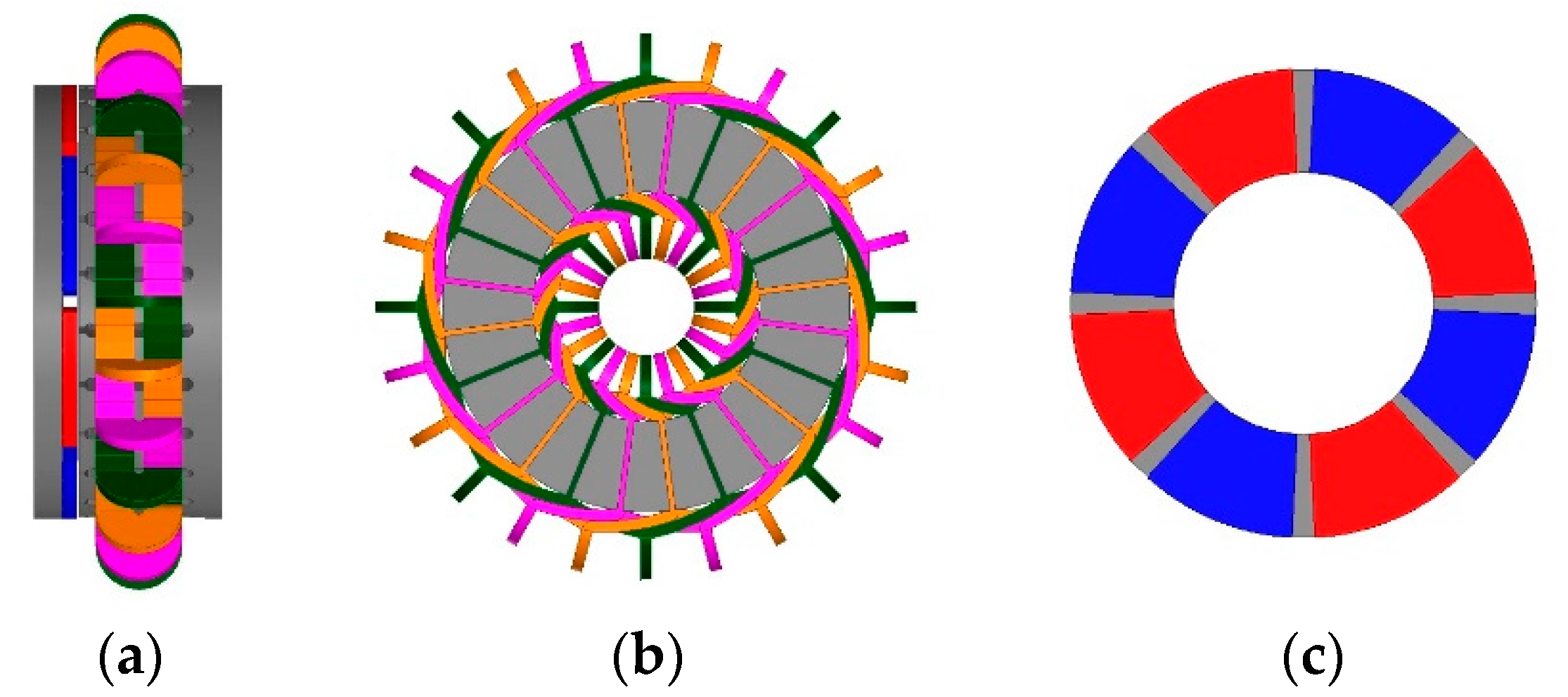
Figure 2.
Magnetic flux path of the AFPM machine in (a) the 2D view and (b) the 3D view.
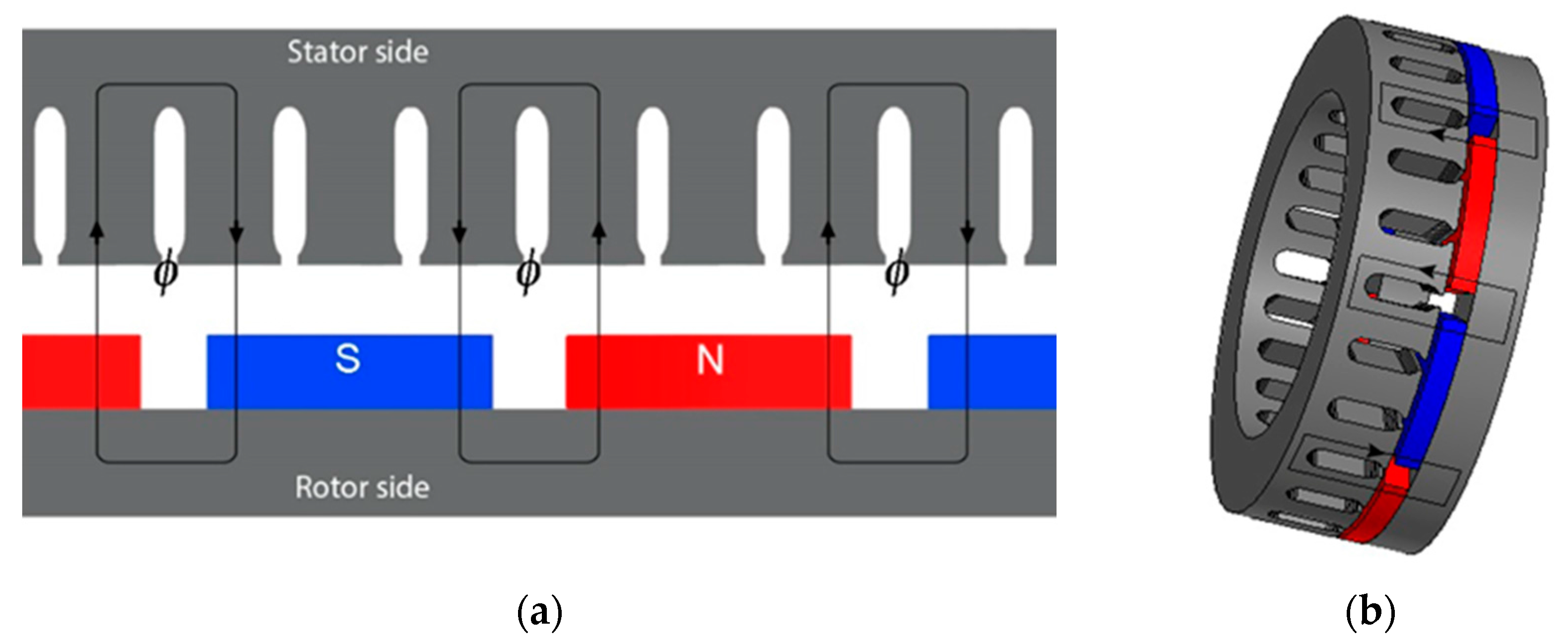
Figure 3.
MAGEC design of the studied single air gap, slotted AFPM machine.
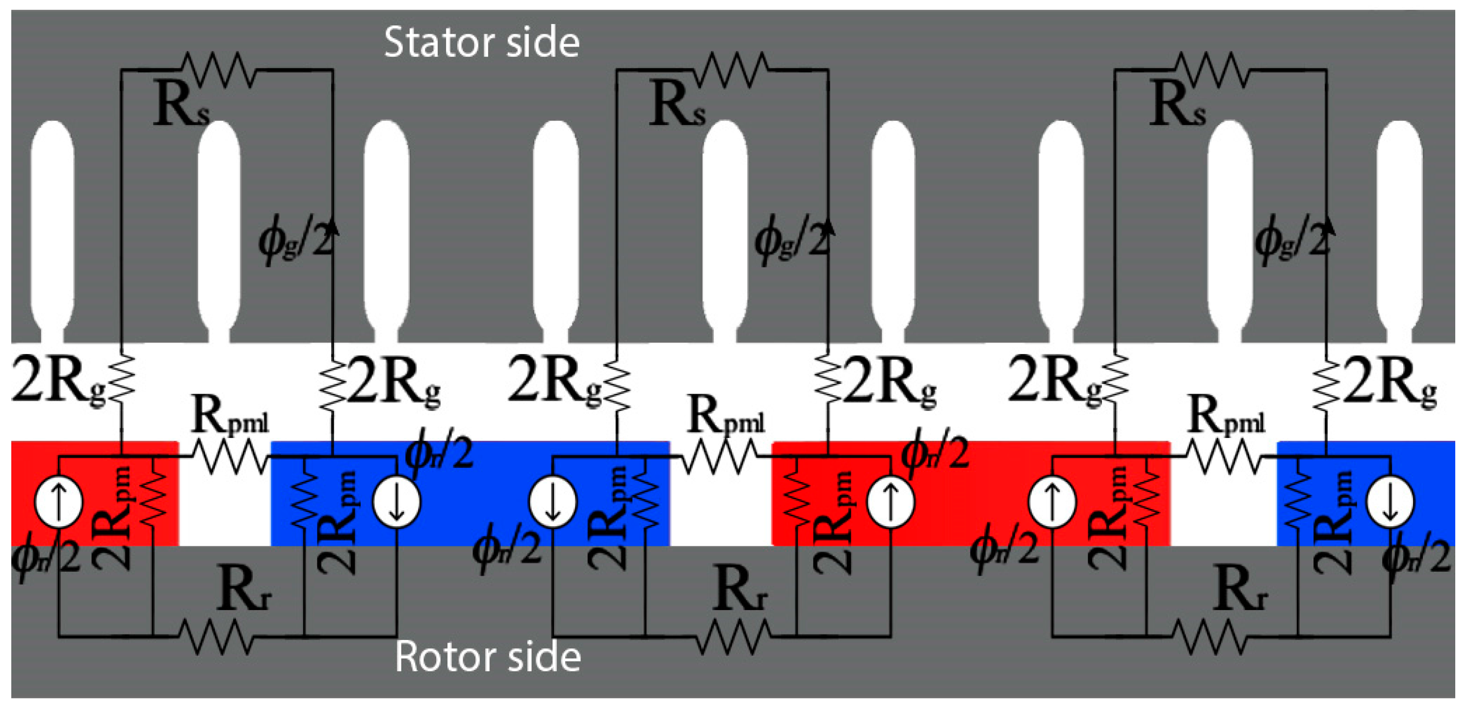
Figure 4.
The simplified MAGEC.

Figure 5.
Simplified MAGEC design in the 2D view of the studied AFPM machine.
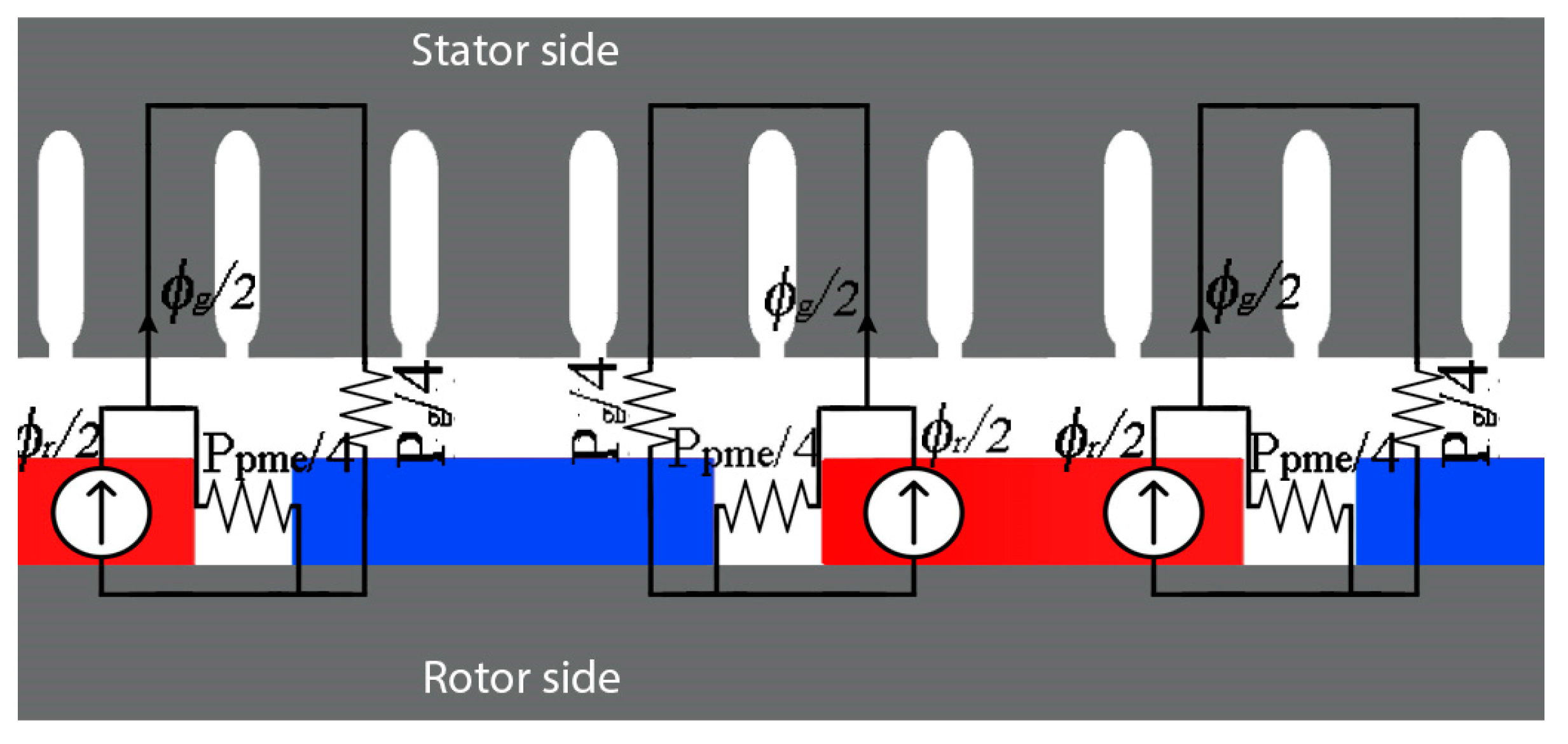
Figure 6.
The researched designs of the magnets.

Figure 7.
¼ part of the simulated AFPM motor designs.
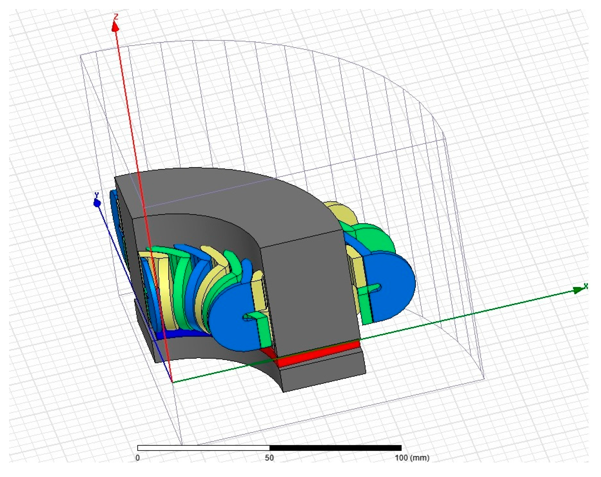
Figure 8.
Defining the shifting angle by 3D-FEA parametric analysis.

Figure 9.
Electromagnetic torque results.

Figure 10.
Back EMF results.

Figure 11.
Flux density distributions for ¼ machine (for 90 mechanical degrees).

Figure 12.
Magnetic flux densities on the surfaces.

Figure 13.
The prototype machine.


Table 1.
The parameters of the single air gap AFPM motor.
| Parameter | Value | Unit |
|---|---|---|
| Inner radius (Di) | 40 | mm |
| Outer radius (Do) | 75 | mm |
| Slot/Pole | 24/8 | |
| Magnet height | 5 | mm |
| Magnet fill factor | 0.8722 | |
| Air gap | 1 | mm |
| Winding | Distributed, overlapping | |
| Turns | 40 | |
| Stator width | 50 | mm |
| Rotor back iron width | 10 | mm |
| Rated Speed | 2200 | rpm |
| Rated current | 175 | A |
Table 2.
Data of the permanent magnet and the steel.
| Permanent Magnet: NdFe–N35 | |
| Br (T) | 1.17 |
| μr | 1.099 |
| Hcb (kA/m) | 868 |
| Hcj (kA/m) | 955 |
| Steel: M250-35A | |
| Bref (T) | 1.5 |
| μr | 660 |
| Loss (W/kg) | 2.5 |
| f (Hz) | 50 |
Table 3.
The results of the 3D-FEA parametric analysis of the shifting angle.
| Shift Angle (Degree) | Average Torque (N·m.) | Torque Ripple (p2p) (N·m.) |
|---|---|---|
| 0 | 49.95 | 5.52 |
| 1 | 49.77 | 6.23 |
| 2 | 51.24 | 6.04 |
| 3 | 51.27 | 5.44 |
| 4 | 50.58 | 5.59 |
| 5 | 50.21 | 5.11 |
| 6 | 50.46 | 5.02 |
| 7 | 50.00 | 4.51 |
| 8 | 49.35 | 4.34 |
| 9 | 49.47 | 3.77 |
| 10 | 48.46 | 2.98 |
| 11 | 48.32 | 2.16 |
| 12 | 47.37 | 3.06 |
| 13 | 45.81 | 3.25 |
| 14 | 45.25 | 4.04 |
Table 4.
The total comparison of the 3D-FEA results.
| Design I | Design II | Design III | Design IV | Design V | |
|---|---|---|---|---|---|
| Average Torque (AT) | 50.521 | 50.25 | 48.32 | 49.28 | 48.59 |
| Torque Ripple (TR) | 5.744 | 3.935 | 2.159 | 5.456 | 3.264 |
| Rate (TR/AT) | 0.114 | 0.078 | 0.045 | 0.111 | 0.067 |
| AT Reduction | ref. | −%0.1 | −%4.3 | −%2.4 | −%3.8 |
| TR Reduction | ref. | −%31.5 | −%62.4 | −%5.1 | −%43.2 |
Table 5.
The average values of parameters by means of the MAGEC and 3D-FEA.
| Average Values of | Simulation | Design I | Design II | Design III | Design IV | Design V |
|---|---|---|---|---|---|---|
| Magnetic Flux Density, Bg (T) | MAGEC | 0.7 | 0.69 | 0.62 | 0.59 | 0.61 |
| 3D-FEA | 0.72 | 0.7 | 0.63 | 0.60 | 0.63 | |
| Back EMF (V) | MAGEC | 17.24 | 16.58 | 14.97 | 14.24 | 14.23 |
| 3D-FEA | 17.643 | 16.878 | 15.1502 | 14.358 | 14.866 | |
| Torque (N·m.) | MAGEC | 49.117 | 49.532 | 47.553 | 48.458 | 47.047 |
| 3D-FEA | 50.521 | 50.25 | 48.32 | 49.28 | 48.59 |
Table 6.
Some of constant values of the AFPM motor counted by MAGEC.
| Values of the Constants | Design I | Design II | Design III | Design IV | Design V |
|---|---|---|---|---|---|
| Kkϕ | 0.8386 | 0.8386 | 0.8386 | 0.8386 | 0.8386 |
| Kpml | 2.09 | 2.2 | 3.04 | 3.46 | 3.17 |
| Kc | 1.04 | 1.04 | 1.04 | 1.04 | 1.04 |
| Cp | 5.96 | 5.96 | 5.96 | 5.96 | 5.96 |
| λ | 0.533 | 0.533 | 0.533 | 0.533 | 0.533 |
© 2018 by the authors. Licensee MDPI, Basel, Switzerland. This article is an open access article distributed under the terms and conditions of the Creative Commons Attribution (CC BY) license (http://creativecommons.org/licenses/by/4.0/).
Share and Cite
MDPI and ACS Style
Cetin, E.; Daldaban, F. Analyzing the Profile Effects of the Various Magnet Shapes in Axial Flux PM Motors by Means of 3D-FEA. Electronics 2018, 7, 13. https://doi.org/10.3390/electronics7020013
AMA Style
Cetin E, Daldaban F. Analyzing the Profile Effects of the Various Magnet Shapes in Axial Flux PM Motors by Means of 3D-FEA. Electronics. 2018; 7(2):13. https://doi.org/10.3390/electronics7020013
Chicago/Turabian StyleCetin, Emrah, and Ferhat Daldaban. 2018. "Analyzing the Profile Effects of the Various Magnet Shapes in Axial Flux PM Motors by Means of 3D-FEA" Electronics 7, no. 2: 13. https://doi.org/10.3390/electronics7020013
Note that from the first issue of 2016, this journal uses article numbers instead of page numbers. See further details here.