A 3D Printing Model Watermarking Algorithm Based on 3D Slicing and Feature Points


1
Department of IT Convergence & Application Engineering, Pukyong National University, Busan 608-737, Korea
2
Department of Information Security, Tongmyong University, Busan 608-711, Korea
*
Author to whom correspondence should be addressed.
Electronics 2018, 7(2), 23; https://doi.org/10.3390/electronics7020023
Submission received: 17 January 2018
/
Revised: 14 February 2018
/
Accepted: 14 February 2018
/
Published: 17 February 2018
Abstract
:With the increase of three-dimensional (3D) printing applications in many areas of life, a large amount of 3D printing data is copied, shared, and used several times without any permission from the original providers. Therefore, copyright protection and ownership identification for 3D printing data in communications or commercial transactions are practical issues. This paper presents a novel watermarking algorithm for 3D printing models based on embedding watermark data into the feature points of a 3D printing model. Feature points are determined and computed by the 3D slicing process along the Z axis of a 3D printing model. The watermark data is embedded into a feature point of a 3D printing model by changing the vector length of the feature point in OXY space based on the reference length. The x and y coordinates of the feature point will be then changed according to the changed vector length that has been embedded with a watermark. Experimental results verified that the proposed algorithm is invisible and robust to geometric attacks, such as rotation, scaling, and translation. The proposed algorithm provides a better method than the conventional works, and the accuracy of the proposed algorithm is much higher than previous methods.
1. Introduction
In recent years, three-dimensional (3D) printing has been widely used in many areas of life [1,2]. 3D printing technology has revolutionized industry, as it allows users to turn any digital file into a physical 3D object. Due to the fact that the benefits of 3D printing are enormous in all domains and the price of a 3D printer is not expensive, an individual user can buy a 3D Printer and download 3D printing models on the Internet to print physical 3D objects. This does great damage to manufacturers, and they need a copyright protection solution for 3D printing models in communications or commercial transactions. Moreover, the original providers also desire means to identify ownership for their products. So, a watermarking solution is suitable and necessary for ownership identification and copyright protection of 3D printing [3].
Previously, there have been many watermarking methods proposed for 3D mesh models [4,5,6,7,8,9,10,11,12,13,14]. However, these methods are only useful for the copyright protection of 3D content or visual applications that use 3D content. They could not be applied to the copyright protection of 3D printing because the output of 3D printing is a physical 3D object. The issue in 3D printing watermarking is how to embed watermark data into 3D printing models and then extract the embedded watermark data from the scanned 3D triangle mesh of a 3D printed object or extract the embedded watermark data from a watermarked 3D printing model in 3D printing processing. For direction on how to extract the embedded watermark data from the scanned 3D triangle mesh of a 3D printed object, some techniques have been recently proposed by some authors [15,16]. These techniques had to use a 3D Scanner in order to scan and construct a 3D triangle mesh from a 3D printed object. However, the accuracy of these methods is very low because they are affected by the resolution of 3D Printers, the quality of 3D Scanners, and noises in the scanning process.
For meeting the issues related to the copyright protection of 3D printing and the weaknesses of the previous methods, we proposed a novel watermarking algorithm for 3D printing in this paper. The main content of the proposed algorithm is to cut a 3D triangle mesh (a 3D printing model) into slices along the Z axis by the 3D slicing process. Slices are then used to extract the intersected points between the 3D triangle mesh and the cutting plane. The feature points of the 3D triangle mesh will be computed from the intersected points and the vertices of the 3D triangle mesh for embedding watermark data. To clarify the proposed algorithm, we organize our paper as follows: In Section 2, we look into previous watermarking techniques for 3D models and explain the relation of the 3D printing process to the proposed algorithm. In Section 3, we show the proposed method in detail. Experimental results and the evaluation of the proposed scheme will be shown in Section 4. Section 5 shows the conclusion.
2. Related Works
2.1. 3D Model Watermarking
3D model watermarking has been extensively researched since the early 2000s. 3D model watermarking schemes are generally focused on the geospatial domain and frequency domain. The main concept of watermarking methods in the geospatial domain is to embed watermark data by modifying the value of vertices or geometric features, such as length, area, or topology, while the main concept of watermarking schemes in the frequency domain is to embed watermark data in the spectrum coefficients of the Discrete Fourier Transform (DFT), Discrete Wavelet Transform (DWT), and Discrete Cosine Transform (DCT) of a sequence of vertices. However, this is not the end purpose of 3D printing watermarking; the end purpose of 3D printing watermarking is to extract the embedded watermark data during the 3D printing process or after the 3D printing process. Consequently, the watermarking schemes for 3D models could not apply to the 3D printing domain.
In the 3D printing watermarking domain, S. Yamazaki et al. [15] proposed a method to extract the embedded watermark from 3D printed objects that are created from 3D triangle meshes. The watermark is embedded in the spread spectrum of a 3D triangle mesh and it is then extracted from the scanned 3D triangle mesh of a 3D printed object. The accuracy of this method is very low because the scanned 3D triangle mesh has many errors in the scanning process and the spread spectrum of a 3D triangle mesh is altered after its transformation to the frequency domain. M. Suzuki et al. [16] presented a method to protect the copyright of 3D printed objects. This method is applied to 3D printers. This method embeds copyright information inside physical 3D objects fabricated with a 3D printer by forming a fine structure inside a 3D printed object as a watermark. This method used a complex hardware system of halogen lights and a laser for experiments, but there is a length limitation on the embedded watermark bits. Moreover, this method does not show how to extract watermark data from a 3D printed object. So, it is not flexible and very expensive.
2.2. 3D Printing-Based Watermarking
Currently, 3D printing technology uses 3D triangle meshes [17] to print physical 3D objects. A 3D triangle mesh is a set of facets. Each facet contains three vertices (a triangle) and a normal vector. Each vertex is presented by three coordinates x, y, and z. In order to print a physical 3D object, a 3D triangle mesh must be cut along the Z axis by a cutting plane from bottom to top via the 3D slicing process [18,19]. The 3D slicing process can be performed by a 3D slicer [20,21]. The output of the 3D slicing process is a set of slices, and the 3D printer prints a physical 3D object from these slices. Figure 1a shows the general 3D printing process.
As mentioned above, a 3D triangle mesh must be cut into slices along the Z axis by a cutting plane from bottom to top before printing a physical 3D object. Each slice is a set of the intersected points between the 3D triangle mesh and the cutting plane. These points are located on a Z plane, which means that the z coordinate of the intersected points is the same (see Figure 1b). Due to the fact that the 3D triangle mesh is sliced from bottom to top by a cutting plane, many vertices of the 3D triangle mesh are cut by the cutting plane. This means that many vertices of the 3D triangle mesh are the intersected points between the 3D triangle mesh and the cutting plane. We consider these points as the feature points of a 3D triangle mesh and select them for embedding watermark data.
3. The Proposed Algorithm
3.1. Overview
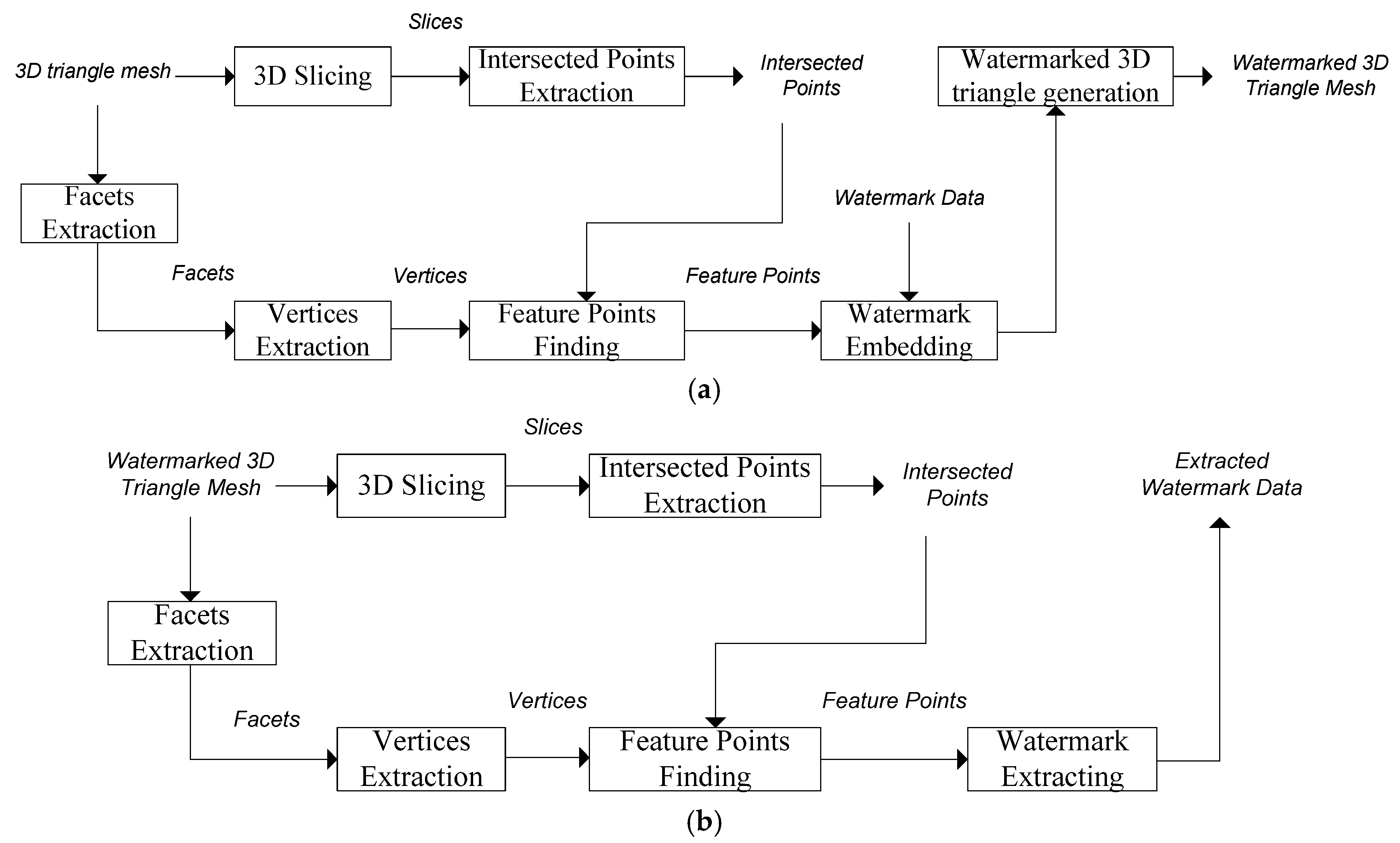
The proposed algorithm is described in Figure 2. A 3D triangle mesh is cut into slices from bottom to top along the Z axis via the 3D slicing process. Slices are then used to extract the intersected points. Besides this, a set of facets is also extracted from the 3D triangle mesh, and facets are then used for vertices extraction. From a set of vertices and a set of the intersected points, we find the feature points of the 3D triangle mesh. The feature points of the 3D triangle are the common points between the vertices of the 3D triangle mesh and the intersected points. After finding the feature points, watermark data will be embedded in each feature point by changing the vector length of each feature point in the OXY space based on the reference length. Next, the x and y coordinates of each feature point will be changed according to the changed vector length that has been embedded with a watermark. The purpose of not changing the z coordinate of the feature point is to gain feature points back from the watermarked 3D triangle mesh in the watermark extraction process. This is because the watermarked 3D triangle mesh will be sliced along the Z axis. If the z coordinate of the feature points is changed, we cannot find the feature points exactly. After embedding watermark data into the feature points, the watermarked 3D triangle mesh will be generated. The watermark extraction process is shown in Figure 2b. It is an inverse of the process for watermark embedding. The details of watermark embedding will be shown in Section 3.3 and those of watermark extraction will be shown in Section 3.4.
3.2. Feature Points Computation
As mentioned above, a 3D triangle mesh contains a set of facets. Facets are connected together to form a 3D triangle mesh; thus, there are many facets that share the same vertices. So, the number of vertices of a 3D triangle mesh is always smaller than the number of facets. To be brief, we consider a 3D triangle mesh , where indicates the facet and |M| represents the cardinalities of a 3D triangle mesh M. Given that V is a set of vertices of a 3D triangle mesh, which is extracted from facets with represents the cardinalities of V. Thus, to extract vertices from a 3D triangle mesh, we have to extract facets and then remove the duplicate vertices as shown in Equation (1). RDV is the Remove Duplicate Vertices function.
A 3D triangle mesh is sliced into a set of slices by the 3D slicing process. Assume that a 3D triangle mesh is cut into a set of slices, where |S| is the number of slices. Each slice is a set of the intersected points, where is the number of the intersected points in slice, andis presented by the coordinates. Now, we can consider that the all of the intersected points are presented by a set of slices S and described in Equation (2):
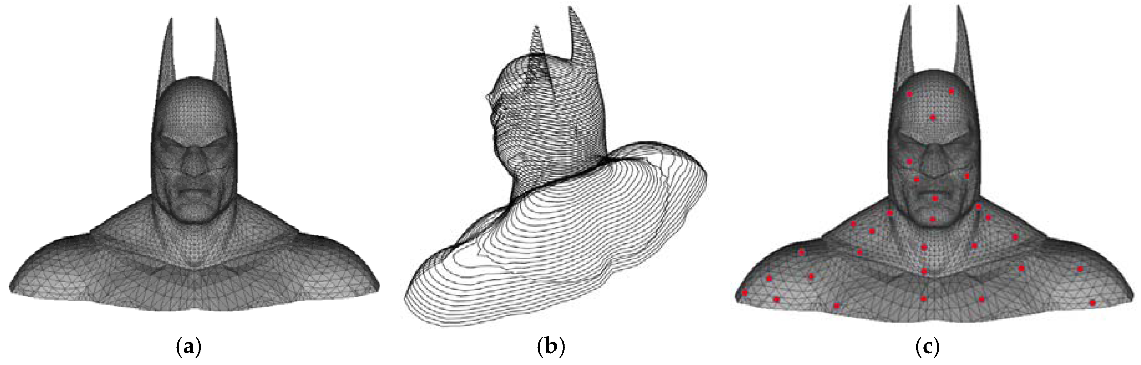
The feature points of a 3D triangle mesh are the vertices of the 3D triangle and also the intersected points. Therefore, they are the common points of the vertices and the intersected points. Suppose is a set of feature points of a 3D triangle mesh; it will be computed by Equation (3). Figure 3 shows the feature points of a Batman model.
3.3. Watermark Embedding
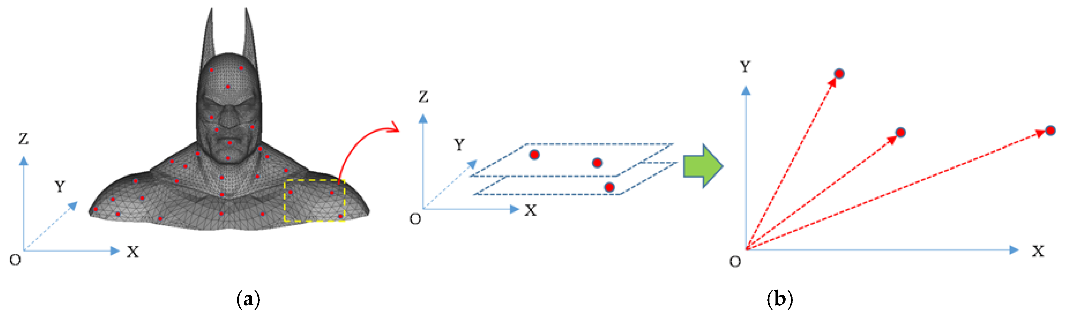
Next, we will embed watermark data into the feature points of the 3D triangle mesh. We can see that feature points which are located on the same cutting plane have the same z coordinates (see Figure 4a). In order to extract the embedded watermark, we must find the watermarked feature points from the watermarked 3D triangle mesh again. Thus, we cannot change the z coordinate of a feature point after embedding a watermark. This means that we can only change the x and y coordinates of a feature point. Due to the fact that we can only change the x and y coordinates of feature points, we have to refer feature points to OXY space (see Figure 4b) and embed watermark data by changing the vector length of a feature point in OXY space based on the reference length. Figure 4 shows feature points in OXYZ space and in OXY space.
Let be the vector length of the feature point in OXY space. It is calculated by Equation (4). Let be the reference length for watermark embedding. To calculate the reference length, we consider the integer part of as and the rounding up of as. , , and are calculated by Equations (5)–(7), respectively.
The number of watermark bits is equal to the number of feature points. Thus, the watermark bit is embedded into the feature point by changing the vector length based on the reference length. If, then will be transformed into that is less than. If, then will be transformed into that is greater than. is the watermarked vector length of the vector length changed according to the watermark bitas shown in Equation (8).
For satisfying the above embedding condition, the watermarked vector length will be changed as follows:
Figure 5 shows the change of the vector length according to the watermark bit. The vector length is represented by the blue point. The watermarked vector length is represented by the red point. Whenis moved to be less thanif. Whenis moved to be greater thanif. After embedding the watermark bitto the vector length, the change rateis calculated as shown in Equation (11):
The watermarked 3D triangle mesh is generated by changing the x and y coordinates of the feature pointaccording the change rate. The feature point is changed to that is the watermarked feature point after watermark embedding and calculated as shown in Equation (12).
3.4. Watermark Extracting
The watermark extraction process is similar to the embedding process. Facets are also extracted from the watermarked 3D triangle mesh. The watermarked 3D triangle mesh is then cut into slices along the Z axis in order to extract the intersected points. From a set of vertices and a set of the intersected points, we can find the watermarked feature points of 3D triangle mesh. For each feature point, we compute the vector length of the watermarked feature point. , and are also calculated respectively as shown in Equations (5)–(7). Finally, the watermark bit can be extracted by comparing with. The condition for watermark extraction is described by Equation (13).
4. Experimental Results and Evaluation
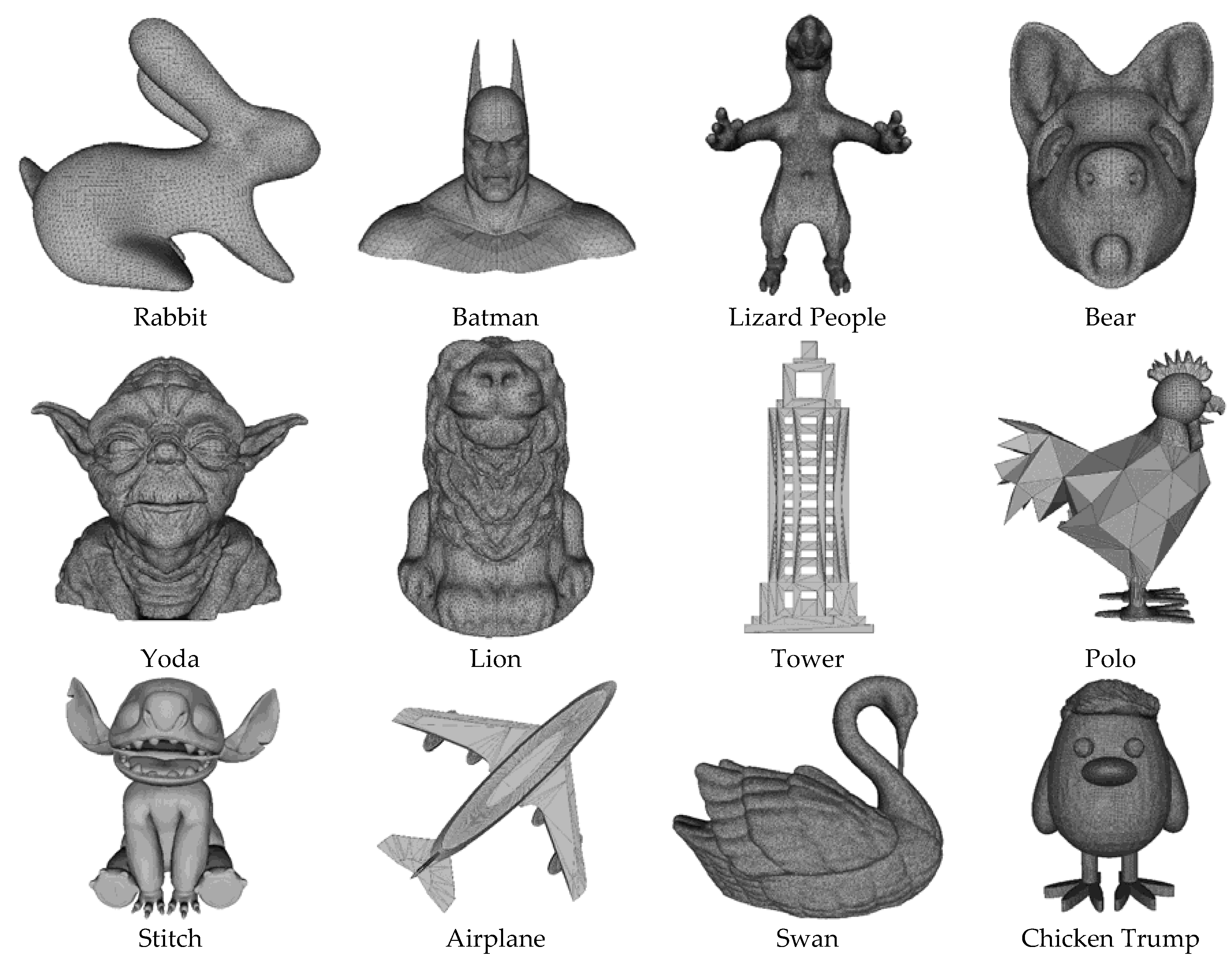
In this section, we experimented on the proposed algorithm with test 3D triangle meshes as shown in Figure 6. The format of a 3D triangle mesh is an STL file [17]. Detailed information on 3D triangle meshes is shown in Table 1. Test 3D triangle meshes are cut into slices along the Z axis of the 3D triangle mesh for finding feature points. The number of slices is dependent on both the Z-axis height of that model and the thickness of the slices. The thickness of the slices is determined by the user. In experiments, we defined the thickness of slices to be 1 mm. After computing the feature points, we embed watermark data into the feature points of the 3D triangle mesh. The number of feature points of each 3D triangle mesh is shown in Table 1. To evaluate the proposed algorithm, we evaluate the invisibility, robustness, and performance. Section 4.1 shows the invisibility evaluation by the distance error. Section 4.2 shows the robustness evaluation, and the performance of the proposed algorithm is shown in Section 4.3.
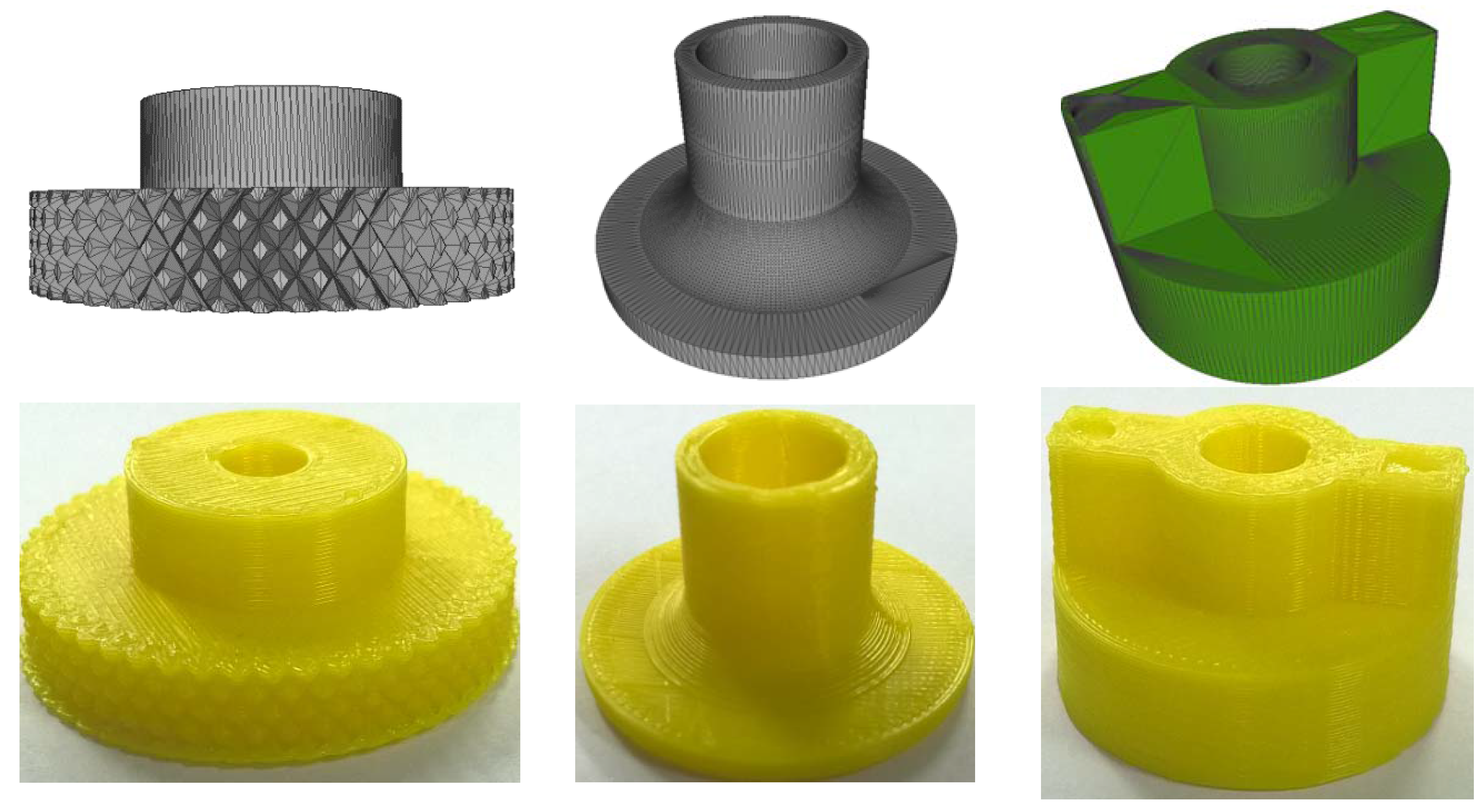
However, to clarify the proposed algorithm, we printed some physical 3D objects by a XYZ Printing Pro 3D Printer [22]. Due to the fact that this 3D Printer is a small printer, it could not print the test models in Figure 6 (these models are large models). So, we did not use the test models in Figure 6. We used small 3D triangle meshes for the printing experiments. The printing results are shown in Figure 7. Physical 3D objects are printed from a set of slices after the 3D slicing process. This proves that we could extract the embedded watermark during the 3D slicing processing of 3D printing.
4.1. Invisibility Evaluation
We calculated the mean Euclidean distance errorbetween the verticesof the watermarked 3D triangle mesh and the verticesof the original 3D triangle mesh to evaluate the invisibility of the proposed algorithm. If the mean Euclidean distance error is small, the invisibility of the proposed algorithm is high and vice versa. The mean Euclidean distance erroris the mean distance error of all distance errors and is calculated as shown in Equation (14).
Table 1 shows the mean distance error between the watermarked 3D triangle mesh and the original 3D triangle mesh corresponding to test 3D triangle meshes. We embedded watermark bits into test 3D triangle meshes according to the number of feature points. The mean distance error between the original 3D triangle mesh and the watermarked 3D triangle mesh is very small (see Table 1). From Equation (14) and Table 1, we can see that the mean distance error is dependent on the number of watermarked feature points and the number of vertices. Table 1 shows the mean distance errors of the original models and the watermarked models. It is from 2.6611 × 10⁻⁶ (minimum) to 1.6932 × 10⁻⁴ (maximum) with the test models. This proves that the difference between the watermarked 3D triangle mesh and the original 3D triangle mesh is very small. Consequently, the invisibility of the proposed algorithm is very high. If we cluster 3D triangle meshes that have a similar number of feature points into groups, we can see that the mean distance error between the original 3D triangle mesh and the watermarked 3D triangle mesh is increased according to the number of feature points. For example: the cluster “Rabbit, Batman, and Lizard People” has a mean distance error of 2.0630 × 10⁻⁶, the cluster “Bear, Yoda, and Lion” has a mean distance error of 3.6195 × 10⁻⁶, and the cluster “Airplane, Chicken Trump, and Swan” has a mean distance error of 0.7020 × 10⁻⁴. Figure 8 shows the mean distance error according to the number of feature points.
4.2. Robustness Evaluation
To evaluate the robustness of the proposed algorithm, we calculate the accuracy of the proposed algorithm with attacks, such as rotation, scaling, translation, and random noises. Translation and rotation only change the spatial location of the 3D triangle mesh in OXYZ space. Scaling changes the size of the 3D triangle mesh. With a rotation attack, it rotates the 3D triangle mesh by an angle; thus, we only align the 3D triangle mesh and slice the 3D triangle mesh along the Z axis for finding feature points. In 3D printing processing, all 3D triangle meshes must be sliced along the Z axis. So, rotation does not affect the watermark extraction process. This means that the proposed algorithm is robust to rotation. With translation, it only moves the position of 3D triangle meshes in OXYZ space. It does not change the Z axis and the volume of the 3D triangle mesh. Thus, when the mesh is cut by the cutting plane from bottom to top, the number of slices and the shape of slices are not changed. This means that the feature points of the 3D triangle mesh are not changed. So, translation does not affect the watermark extraction process. With a scaling attack, it increases or reduces the size of the 3D triangle mesh but it does not change the center of the 3D triangle mesh. To re-scale, we have two ways. In the first way, we find the highest vertex and the lowest vertex on the original 3D triangle mesh. We then calculate the distance between these vertices. With the scaled 3D triangle mesh, we also perform a similar calculation. Finally, we compare the distances to find the scale-ratio for the re-scaling process. In the second way, we find the center of the 3D triangle mesh. Because a scaling attack does not change the center of the 3D triangle mesh, we can consider the center of the 3D triangle mesh to be the origin coordinates and calculate the distance from the center of the 3D triangle mesh to the lowest vertex or to the highest vertex. Finally, we also compare the distances to find the scale-ratio for the re-scaling process. In order to evaluate the robustness of the proposed algorithm with random noises, we experimented with random noises that have ratios of 1%, 5%, and 10%, respectively.
We calculate the accuracy by comparing the extracted watermark data with the original watermark data:
The accuracy of the proposed algorithm with random noises is shown in Table 2. With differential noises, the accuracy with each 3D triangle mesh is also different. The reason for this difference is noise affecting both the feature points and the height of the 3D triangle mesh. Random noise firstly changes the coordinates of the vertices, which changes the height of a 3D triangle mesh. This moves the number of slices and the intersected points. Therefore, the feature points of 3D triangle meshes are also changed. Secondly, random noise directly affects the feature points of a 3D triangle mesh; thus, the extracted watermark bits are incorrect. From Table 2, we can see that with no noise the accuracy is 100%, while with noises that have ratios of 1%, 5%, and 10%, respectively, the average accuracy is decreased from 78.05% to 57.24%.
We compare the robustness of the proposed algorithm with the conventional works by comparing the accuracy of methods with noise attacks. In Mona’s method [9], he experimented with four models and with noises that have ratios of 0.1%, 0.3%, and 0.5%, respectively. The accuracy of Mona’s method is decreased from 99.30% to 81.92% with noises that have ratios of 0.1%, 0.3%, and 0.5%. In Rolland’s method [10], he experimented with 13 models with noises that have ratios of 0.1%, 1%, and 5%, respectively. The accuracy of Rolland method is decreased from 98% to approximately 53%. Due to the fact that the conventional works experimented with very low noises, the proposed algorithm is more robust than the conventional works. Figure 9 shows the robustness comparison between the proposed algorithm and the conventional works.
4.3. Performance Evaluation
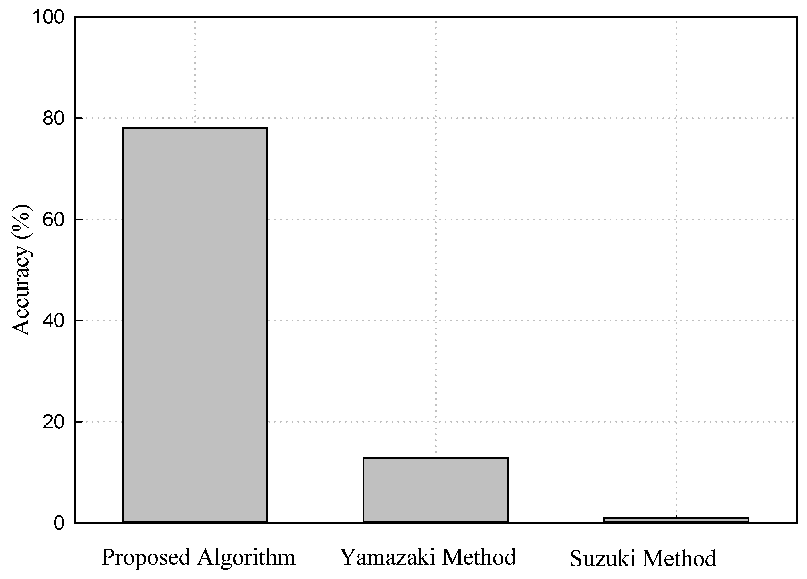
In order to evaluate the performance of the proposed algorithm, we compare the accuracy of the proposed algorithm with the recent proposed methods for 3D printing. In the Yamazaki method [15], the watermark data is embedded by inserting watermark bits into the spectrum of decomposition and modulation in the frequency domain. Watermark data is extracted from the scanned 3D triangle mesh of 3D printed objects. The weakness of the Yamazaki method is that the length of watermark bits is fixed and equals 256 bits. Therefore, there is a limitation on the number of watermark bits that can be embedded into 3D triangle meshes. Moreover, the spectrum of decomposition and modulation is affected by the transformation process from the spatial domain to the frequency domain and by noise in the 3D scanning process. So, the percentage to be precise for a casting object is 12.8% in Yamazaki’s method. This means we could consider that the accuracy of Yamazaki method is 12.8%. In Suzuki’s method [16], the watermark data is embedded into the 3D printed object in the 3D printing process by a halogen light and laser system. It requires a complex hardware system, but it could not embed all expected watermark bits inside the 3D printed object. In addition, Suzuki’s method does not describe how to extract watermark data from 3D printed objects. Finally, Suzuki did not show the accuracy of his method. In our method, the accuracy is 100% without noise and decreases from 78.05% to 57.24% with noises that have ratios of 1%, 5%, and 10%, respectively. This proves that the performance of the proposed algorithm is higher than previous methods. Assuming that in a real environment noise is always 1%, the accuracy of the proposed algorithm is 78.05%. Figure 10 shows the performance of the proposed algorithm compared to previous methods. Consequently, the proposed algorithm is better than previous methods.
5. Conclusions
We proposed a novel watermarking algorithm for 3D printing without a 3D scanner in this paper. The proposed algorithm embeds watermark data to the feature points of a 3D triangle mesh by changing the vector length of feature points in OXY space. The feature points of a 3D triangle mesh are computed from the vertices of 3D triangle meshes and the intersected points between the 3D triangle mesh and the cutting plane. Experiments proved that the proposed algorithm is invisible and robust to geometric attacks, such as rotation, translation, and scaling. The accuracy of the proposed algorithm is higher than that of previous methods. Compared to the conventional works, the robustness of the proposed algorithm is better than that of the conventional works. At present, we are finding the way to integrate our algorithm into applications for 3D Printers. In addition, we are improving the proposed algorithm by changing the thickness of the slice in the 3D printing process to remove effects on the slices. Next time, we will consider applying the proposed algorithm to a copyright protection system or 3D watermarking protocol or experiment on the proposed algorithm with 3D Printers.
Acknowledgments
This research is supported by the Basic Science Research Program through the National Research Foundation of Korea (NRF) funded by the Ministry of Science and ICT (No. 2016R1D1A3B03931003, No. 2017R1A2B2012456), the MSIP (Ministry of Science and ICT), Korea, under the Grand Information Technology Research Center support program (IITP-2017-2016-0-00318) supervised by the IITP (Institute for Information & communications Technology Promotion), and the Institute for Information & communications Technology Promotion (IITP) grant funded by the Korea government (MSIT) (No. 2015-0-00225) and the Brain Busan 21 (BB21) project in 2017.
Author Contributions
In this research activity, all of the authors joined and researched in the data analysis and preprocessing phases, the simulation, the results analysis and discussion, and the manuscript’s preparation. All of the authors have approved the submitted manuscript. All of the authors equally contributed to the writing of the paper.
Conflicts of Interest
The authors declare no conflict of interest.
References
- How 3D Printing Works: The Vision, Innovation and Technologies Behind Inkjet 3D Printing; 3D Systems: Rock Hill, CA, USA, 2012; Available online: http://www.officeproductnews.net/sites/default/files/3dWP_0.pdf (accessed on 16 February 2018).
- Lidia, H.A.; Paul, A.J.; Jose, R.J.; Will, H.; Vincent, C. Ascent. White Paper: 3D Printing; Atos: Irving, TX, USA, 2014; Available online: https://atos.net/wp-content/uploads/2016/06/01052014-AscentWhitePaper-3dPrinting-1.pdf (accessed on 16 February 2018).
- Ira, S.; Parker, S. Copyright Issues in 3D Printing. In Proceedings of the International Technology Law Conference, Paris, France, 1–14 October 2014. [Google Scholar]
- Ai, Q.; Liu, Q.; Zhou, D.; Yang, L.; Xi, Q. A new digital watermarking scheme for 3D triangular mesh models. J. Signal Process. 2009, 89, 2159–2170. [Google Scholar] [CrossRef]
- Tamane, C.; Ratnadeep, R. Blind 3D Model Watermarking Based on Multi-Resolution Representation and Fuzzy Logic. Int. J. Comput. Sci. Inf. Technol. 2012, 4, 117–126. [Google Scholar] [CrossRef]
- Tan, X.H. A 3D Model Asymmetric Watermarking Algorithm Based on Optimization Statistics. J. Theor. Appl. Inf. Technol. 2011, 51, 175–181. [Google Scholar]
- Hu, Q.; Lang, Z. The study of 3D Digital Watermarking Algorithm Which is based on a Set of Complete System of Legendre Orthogonal Function. Open Autom. Control Syst. J. 2014, 6, 1710–1716. [Google Scholar] [CrossRef]
- Liu, J.; Wang, Y.; He, W.; Li, Y. A New Watermarking Method of 3D Mesh Model. Indones. J. Electr. Eng. 2014, 12, 1610–1617. [Google Scholar] [CrossRef]
- Mona, M.; Ella, A.; Hoda, O. Robust Watermarking Approach for 3D Triangular Mesh using Self Organization Map. In In Proceedings of the 8th International Conference on Computer Engineering & Systems, Cairo, Egypt, 26–28 November 2013; pp. 99–104. [Google Scholar]
- Rolland, X.; Do, D.; Pierre, A. Triangle Surface Mesh Watermarking based on a Constrained Optimization Framework. IEEE Trans. Inf. Forensics Secur. 2014, 9, 1491–1501. [Google Scholar] [CrossRef]
- Ho, J.U.; Kim, D.G.; Choi, S.H.; Lee, H.K. 3D Print-Scan Resilient Watermarking Using a Histogram-Based Circular Shift Coding Structure. In Proceedings of the 3rd ACM Workshop on Information Hiding and Multimedia Security, Portland, OR, USA, 17–19 June 2015; pp. 115–121. [Google Scholar]
- Hou, J.U.; Kim, D.G.; Lee, H.K. Blind 3D Mesh Watermarking for 3D Printed Model by Analyzing Layering Artifact. EEE Trans. Inf. Forensics Secur. 2017, 12, 2712–2725. [Google Scholar] [CrossRef]
- Feng, X.; Liu, Y.; Fang, L. Digital Watermark of 3D CAD Product Model. Int. J. Secur. Appl. 2015, 9, 305–320. [Google Scholar] [CrossRef]
- Wang, Y.; Jing, L.; Yang, Y.; Ma, D.; Liu, R. 3D model watermarking algorithm robust to geometric attacks. IET Image Proc. 2017, 11, 822–832. [Google Scholar] [CrossRef]
- Yamazaki, S.; Satoshi, K.; Masaaki, M. Extracting Watermark from 3D Prints. In Proceedings of the 22nd International Conference on Pattern Recognition, Stockholm, Sweden, 24–28 August 2014; pp. 4576–4581. [Google Scholar]
- Suzuki, M.; Piyarat, S.; Kazutake, U.; Hiroshi, U.; Takashima, Y. Copyright Protection for 3D Printing by Embedding Information inside Real Fabricated Objects. In Proceedings of the 10th International Conference on Computer Vision Theory and Applications, Berlin, Germany, 11–14 March 2015; pp. 180–185. [Google Scholar]
- STL Format in 3D Printing. Available online: https://all3dp.com/what-is-stl-file-format-extension-3d-printing/ (accessed on 13 February 2018).
- Munir, E. Slicing 3D CAD Model in STL Format and Laser Path Generation. Int. J. Innov. Manag. Technol. 2013, 4, 410–413. [Google Scholar] [CrossRef]
- Vatani, M.; Rahimi, R.; Brazandeh, F.; Sanatinezhad, A. An Enhanced Slicing Algorithm Using Nearest Distance Analysis for Layer Manufacturing. Int. J. Mech. Aerosp. Ind. Mechatron. Manuf. Eng. 2009, 3, 74–79. [Google Scholar]
- 3D Slicer. Available online: https://www.slicer.org/ (accessed on 13 February 2018).
- KIS Slicer. Available online: http://www.kisslicer.com/ (accessed on 13 February 2018).
- XYZ Pro 3 in 1 Printer. Available online: https://www.xyzprinting.com/en-US/product/da-vinci-1-0-pro-3-in-1 (accessed on 13 February 2018).
Figure 1.
(a) General three-dimensional (3D) Printing Process; (b) 3D Triangle Mesh Slicing in OYZ space and in OXYZ space.
Figure 1.
(a) General three-dimensional (3D) Printing Process; (b) 3D Triangle Mesh Slicing in OYZ space and in OXYZ space.
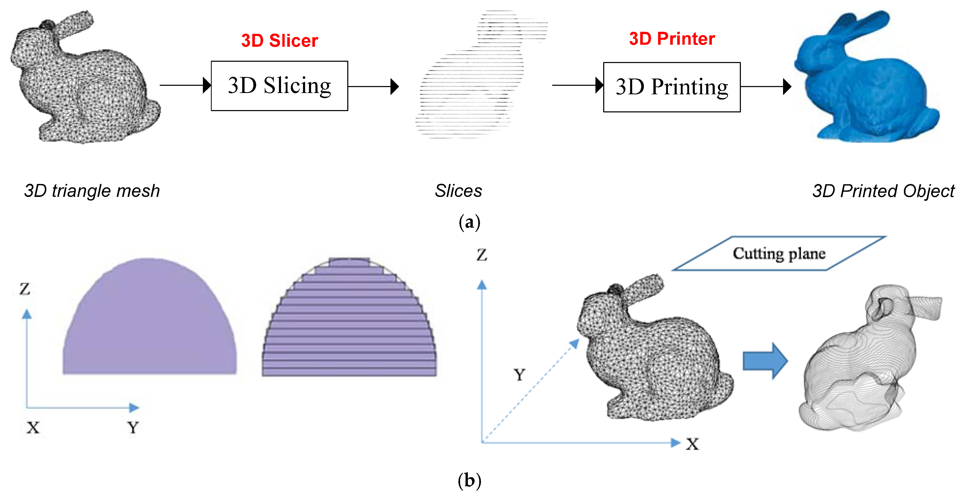
Figure 2.
The proposed algorithm: (a) watermark embedding and (b) watermark extraction.

Figure 3.
(a) 3D triangle mesh with vertices; (b) the 3D triangle mesh is cut into slices; and (c) feature points of the 3D triangle mesh.
Figure 3.
(a) 3D triangle mesh with vertices; (b) the 3D triangle mesh is cut into slices; and (c) feature points of the 3D triangle mesh.

Figure 4.
(a) Feature points in OXYZ space; and (b) feature points in OXY space.

Figure 5.
Watermark bit embedding by changing the vector length of a feature point.
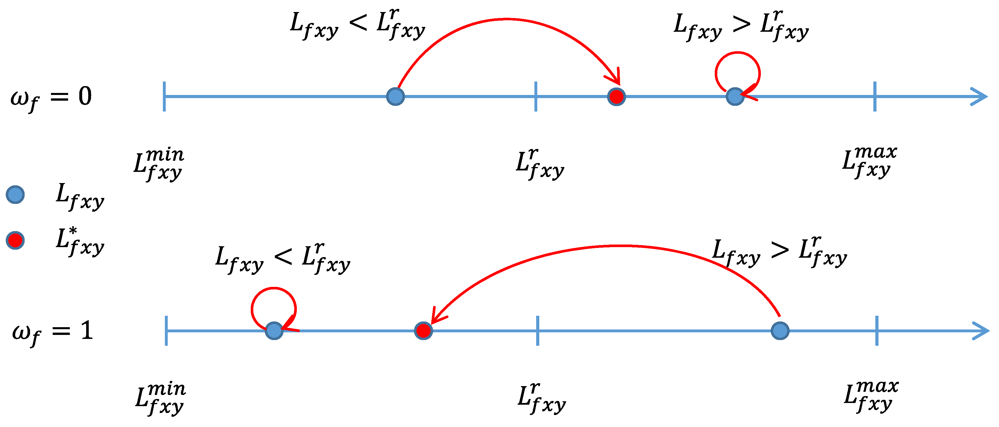
Figure 6.
Test Models.

Figure 7.
3D printed objects.

Figure 8.
Distance error according to the number of feature points.
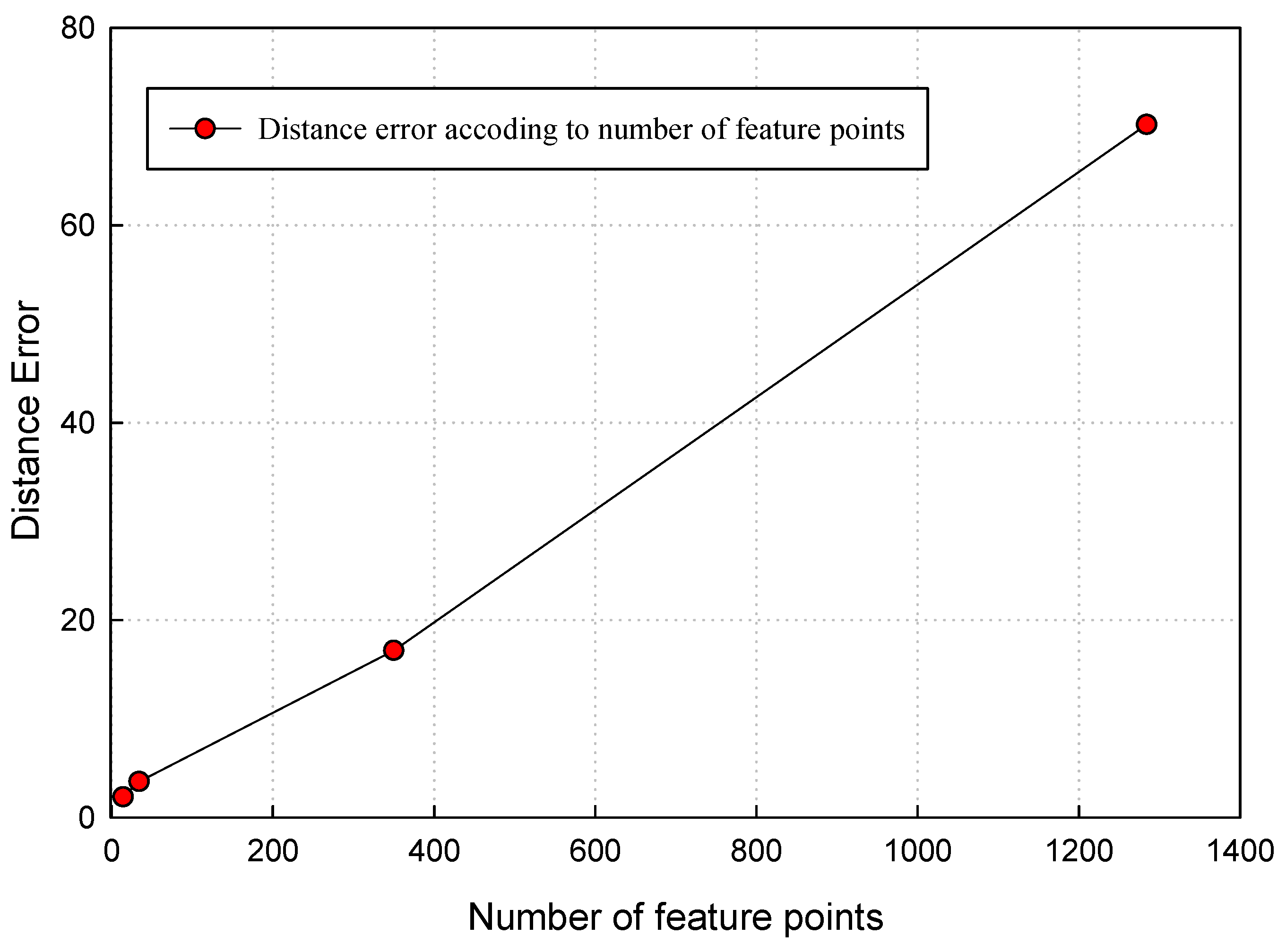
Figure 9.
Robustness of the proposed method with noise attack.
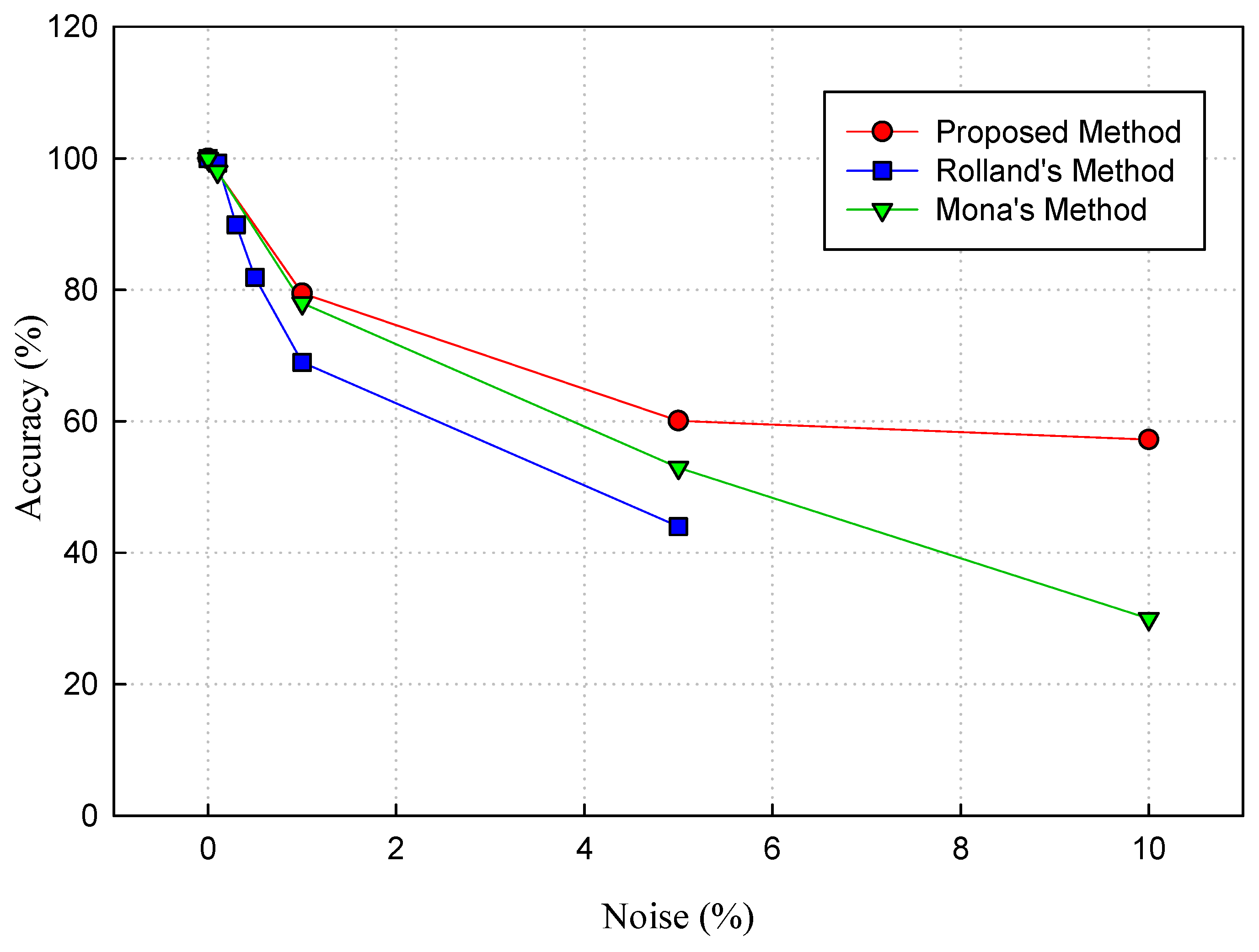
Figure 10.
Performance of the proposed algorithm compared to other methods.


Table 1.
Distance Error.
| Name | # Vertices | # Feature Point | Distance Error |
|---|---|---|---|
| Rabbit | 10,530 | 11 | 2.6611 × 10⁻⁶ |
| Batman | 6785 | 12 | 0.1079 × 10⁻⁶ |
| Lizard People | 34,625 | 19 | 3.4201 × 10⁻⁶ |
| Bear | 20,248 | 34 | 0.1099 × 10⁻⁶ |
| Yoda | 24,910 | 34 | 7.0214 × 10⁻⁶ |
| Lion | 39,583 | 35 | 3.7276 × 10⁻⁶ |
| Tower | 1311 | 48 | 1.6932 × 10⁻⁴ |
| Polo | 8526 | 263 | 1.5386 × 10⁻⁴ |
| Stitch | 384,034 | 737 | 0.1020 × 10⁻⁴ |
| Airplane | 2796 | 1072 | 0.7655 × 10⁻⁴ |
| Chicken Trump | 49,424 | 1194 | 1.2391 × 10⁻⁴ |
| Swan | 70,682 | 1587 | 0.1013 × 10⁻⁴ |
Table 2.
Robustness Evaluation.
| Name | Accuracy (%) | |||
|---|---|---|---|---|
| No Noise | Noise 1% | Noise 5% | Noise 10% | |
| Rabbit | 100 | 100 | 100 | 54.54 |
| Batman | 100 | 83.33 | 58.33 | 58.33 |
| Lizard People | 100 | 94.74 | 52.63 | 57.89 |
| Bear | 100 | 94.12 | 32.35 | 52.94 |
| Yoda | 100 | 100 | 76.47 | 76.47 |
| Lion | 100 | 45.71 | 45.71 | 51.43 |
| Tower | 100 | 50.00 | 58.33 | 58.33 |
| Polo | 100 | 80.61 | 62.74 | 51.33 |
| Stitch | 100 | 75.71 | 51.29 | 52.78 |
| Airplane | 100 | 99.22 | 83.12 | 68.67 |
| Chicken Trump | 100 | 58.46 | 51.67 | 53.01 |
| Swan | 100 | 54.66 | 48.51 | 51.21 |
| Average | 100 | 78.05 | 60.10 | 57.24 |
© 2018 by the authors. Licensee MDPI, Basel, Switzerland. This article is an open access article distributed under the terms and conditions of the Creative Commons Attribution (CC BY) license (http://creativecommons.org/licenses/by/4.0/).
Share and Cite
MDPI and ACS Style
Pham, G.N.; Lee, S.-H.; Kwon, O.-H.; Kwon, K.-R. A 3D Printing Model Watermarking Algorithm Based on 3D Slicing and Feature Points. Electronics 2018, 7, 23. https://doi.org/10.3390/electronics7020023
AMA Style
Pham GN, Lee S-H, Kwon O-H, Kwon K-R. A 3D Printing Model Watermarking Algorithm Based on 3D Slicing and Feature Points. Electronics. 2018; 7(2):23. https://doi.org/10.3390/electronics7020023
Chicago/Turabian StylePham, Giao N., Suk-Hwan Lee, Oh-Heum Kwon, and Ki-Ryong Kwon. 2018. "A 3D Printing Model Watermarking Algorithm Based on 3D Slicing and Feature Points" Electronics 7, no. 2: 23. https://doi.org/10.3390/electronics7020023
Note that from the first issue of 2016, this journal uses article numbers instead of page numbers. See further details here.