Suppression of the Second Harmonic Subgroup Injected by an AC EAF: Design Considerations and Performance Estimation of a Shunt APF


Abstract
:1. Introduction
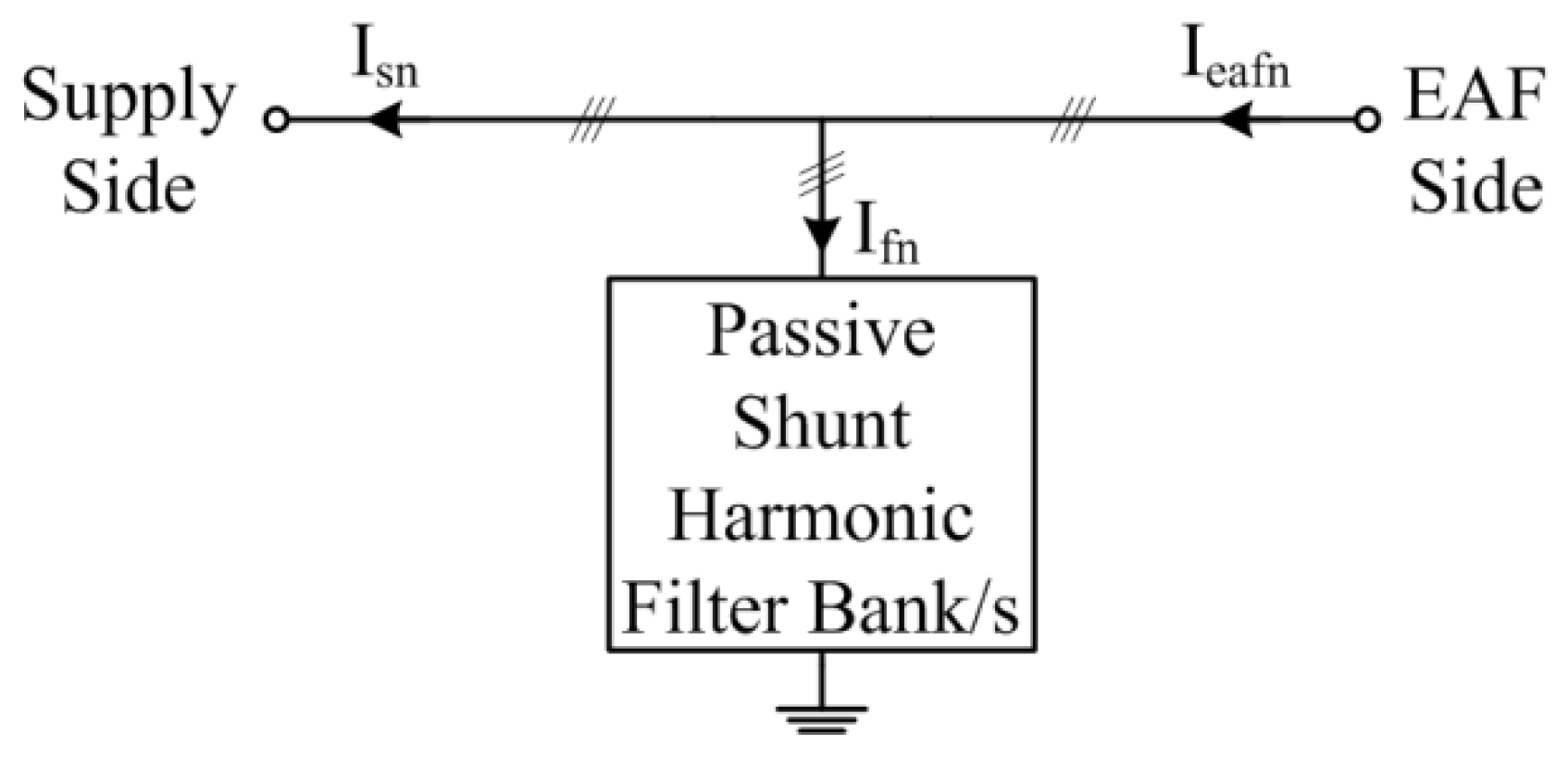
2. Problem Definition
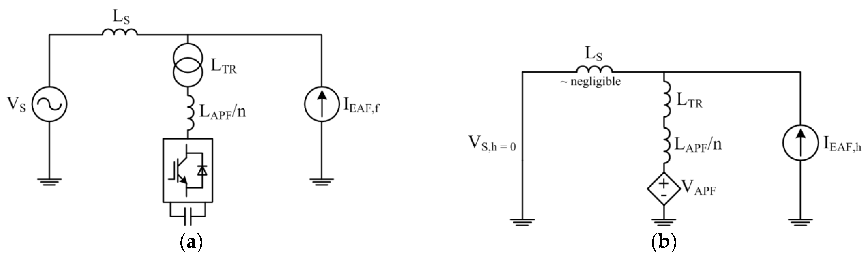
3. Proposed Hybrid Solution Including APF
4. Proposed APF Design Methodology
4.1. Determination of the Maximum RMS Value of the Second Harmonic Subgroup
- (i)
- for the vast majority of the operating time, the true RMS value is lower than 166.3 A;
- (ii)
- the peak values of the subgroup current harmonic components rarely coincide in time;
- (iii)
- the optimum solution to the preliminary design study is chosen to be the minimization of the second harmonic subgroup currents instead of the elimination of them entirely; and
- (iv)
- the fundamental current component flowing through the coupling transformer compensates only for APF switching and conduction losses and to magnetize the transformer core. Since it is much lower than the true RMS value of the second harmonic subgroup, it is neglected in the preliminary design procedure.
4.2. Estimation of Coupling Transformer MVA Rating
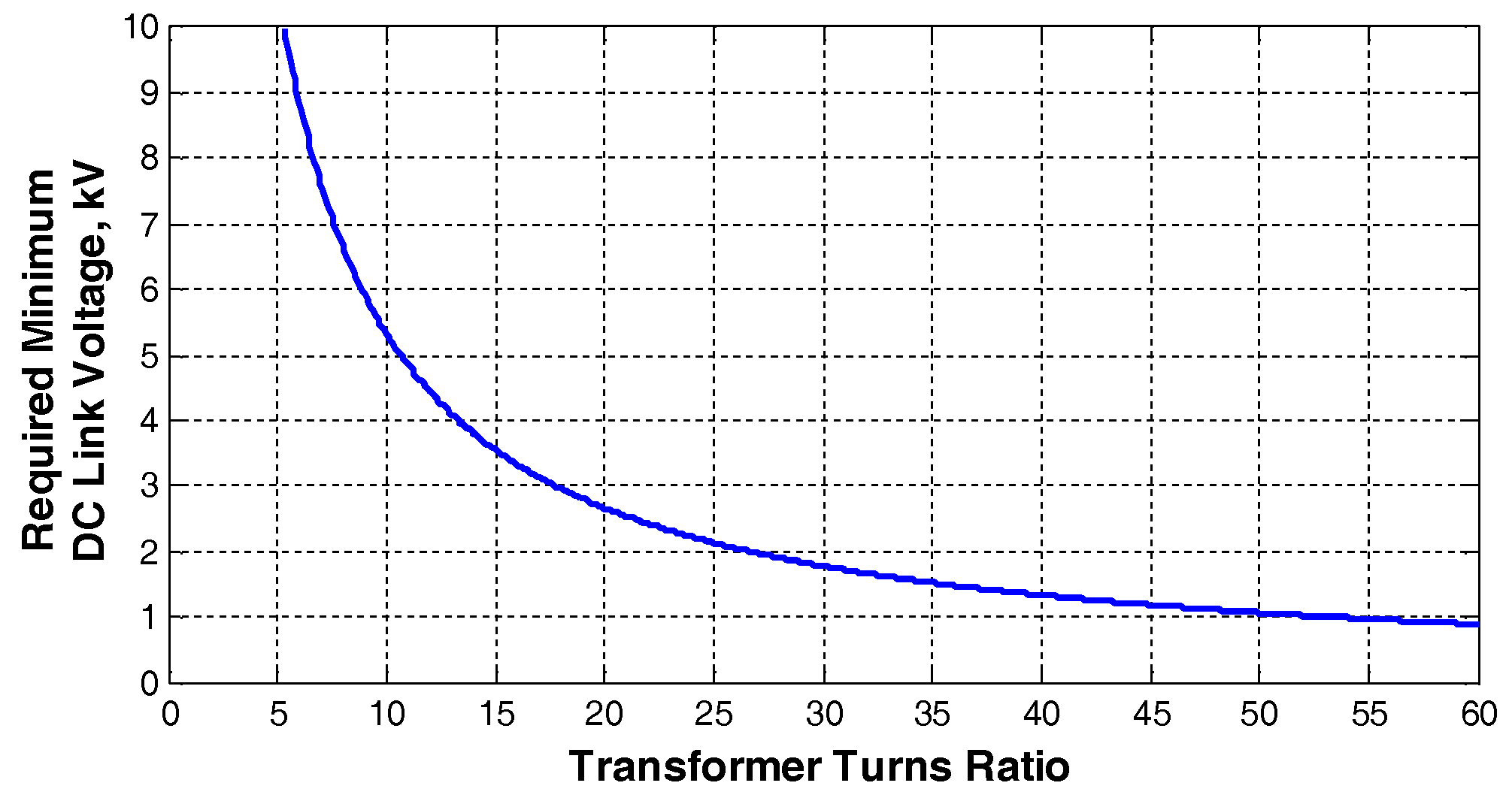
4.3. Estimation of Transformer Secondary Voltage
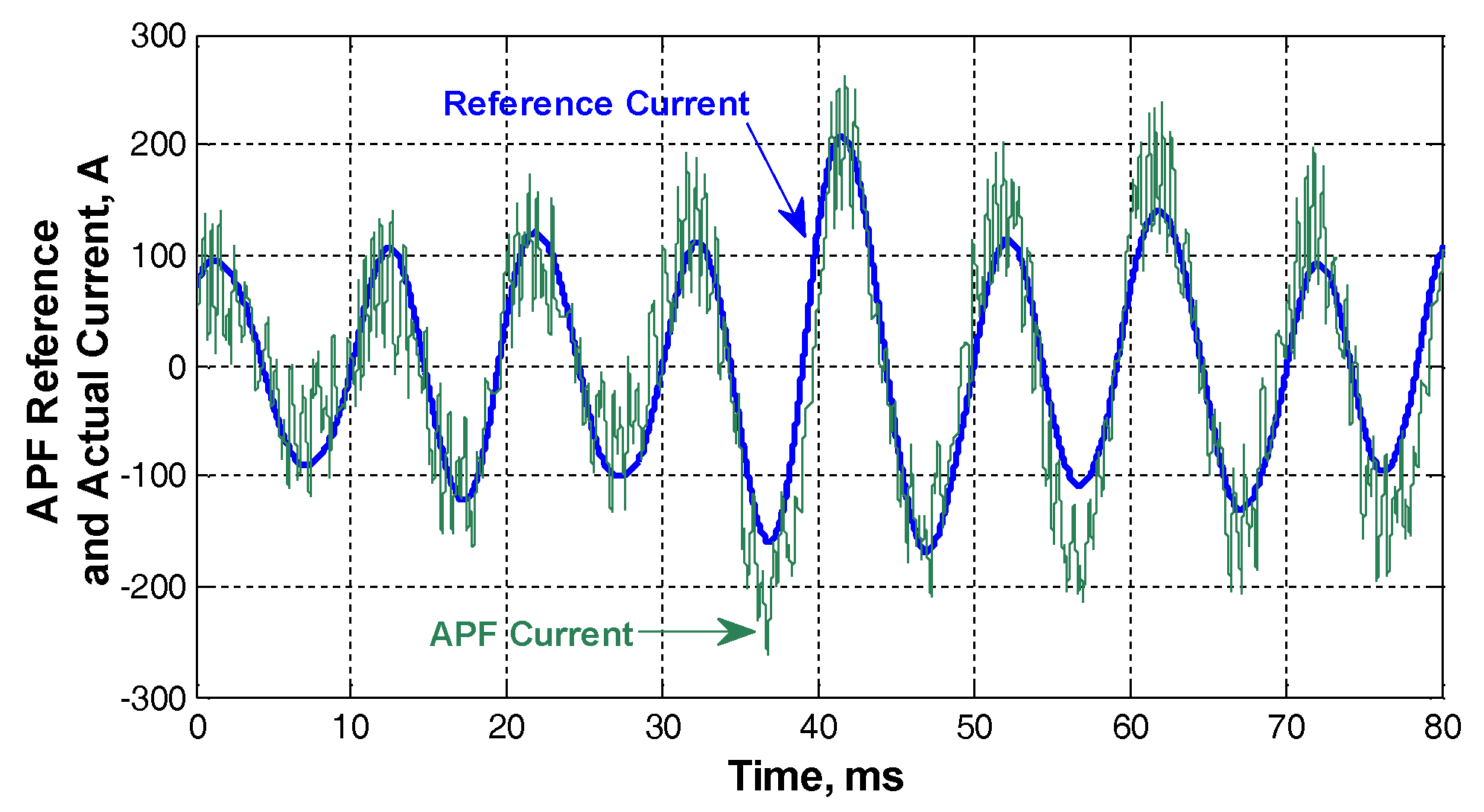
4.4. Proposed Control Strategy
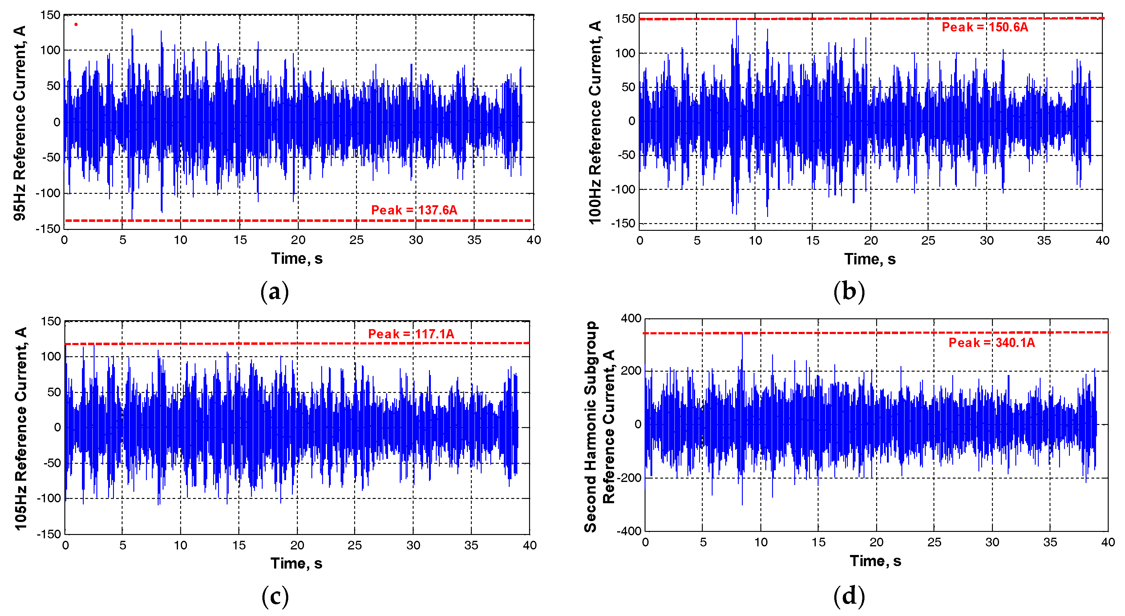
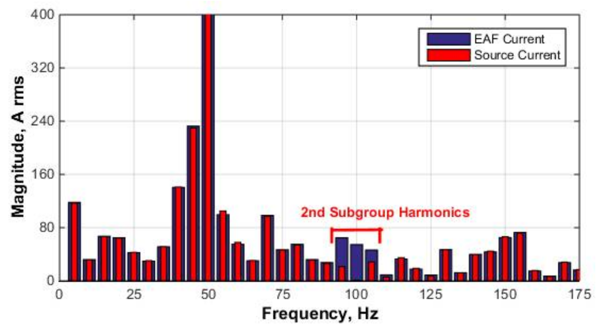
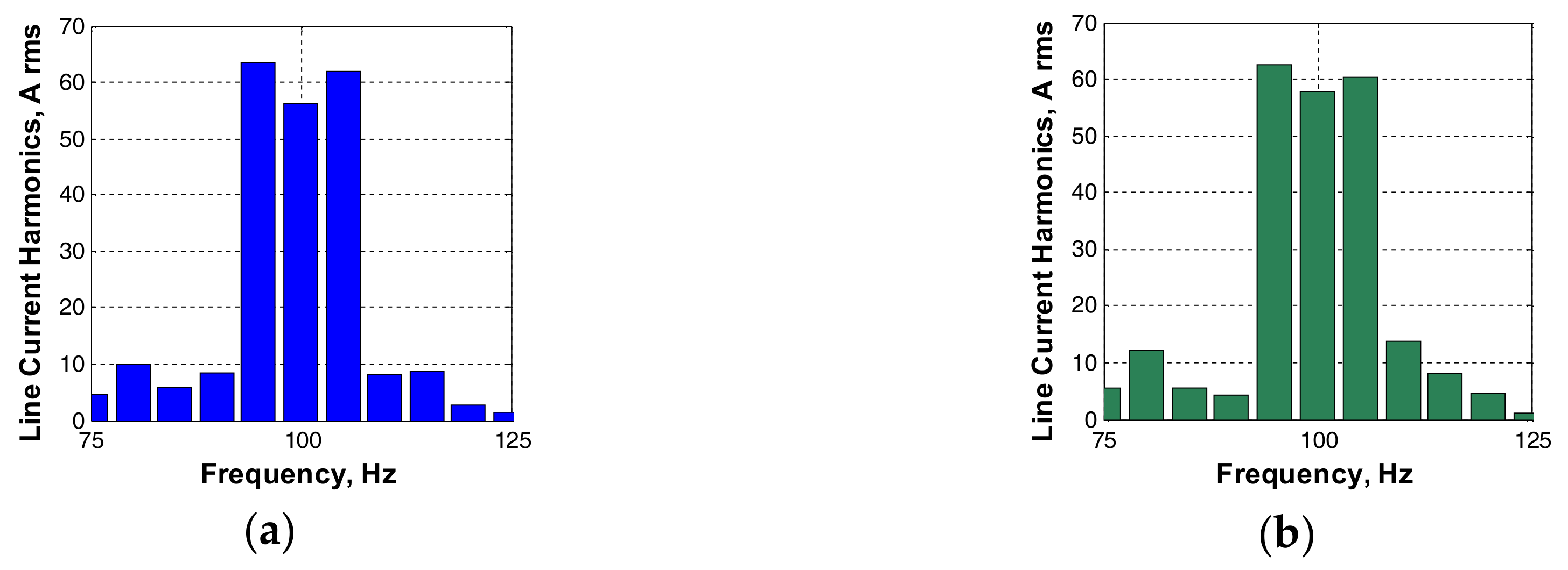
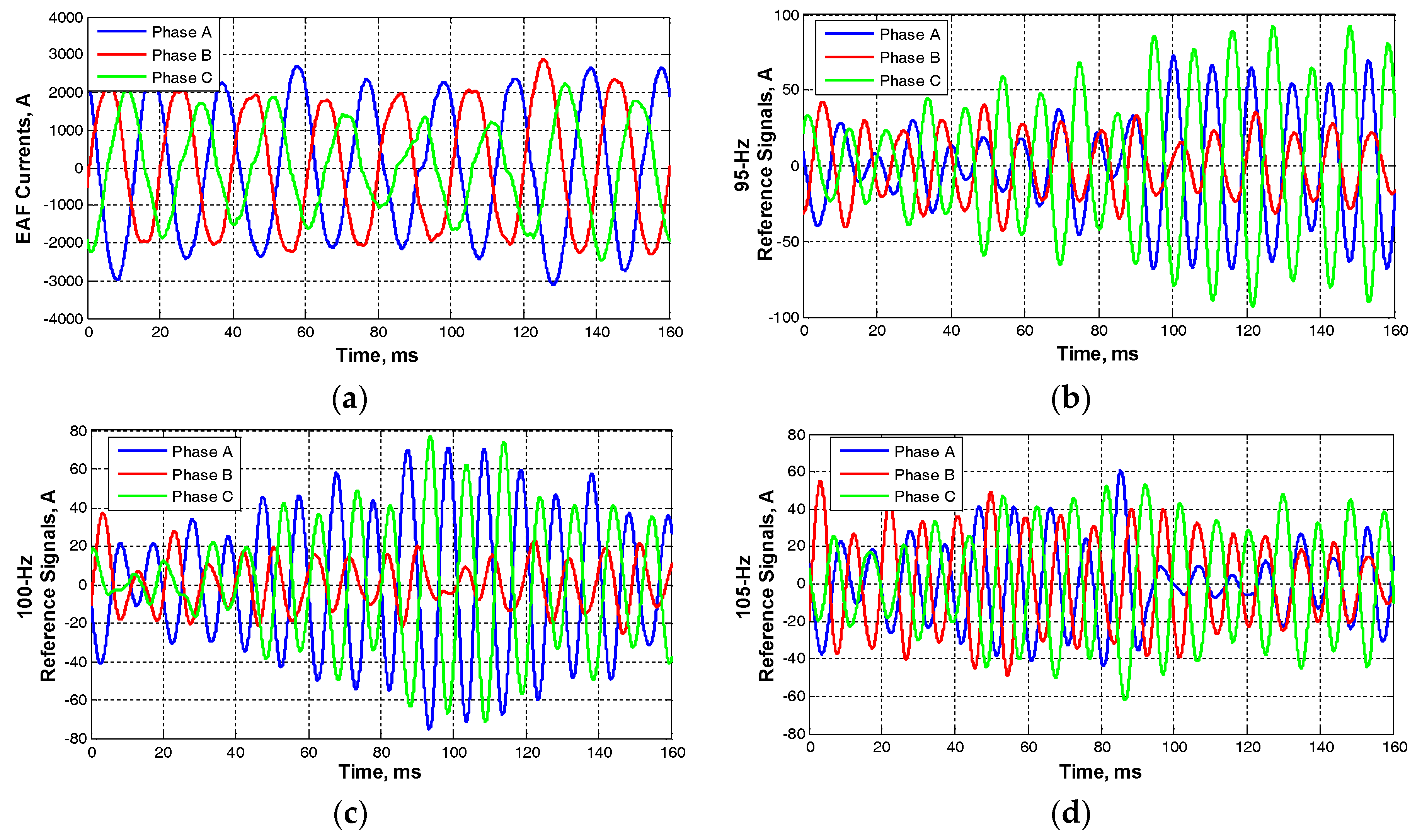
5. Performance of Proposed APF System by EMTDC/PSCAD Simulations
- (a)
- 100-Hz component is eliminated;
- (b)
- 95- and 105-Hz components are significantly suppressed;
- (c)
- The non-idealities in the performance are attributed to the facts that extraction of interharmonic and harmonic components using MSRF analysis in real-time may lead to small magnitude and phase errors, hence, the APF system cannot suppress the second harmonic subgroup perfectly.
- (d)
- The proposed APF system does not affect interharmonic and harmonic current components other than the second harmonic subgroup; and
- (e)
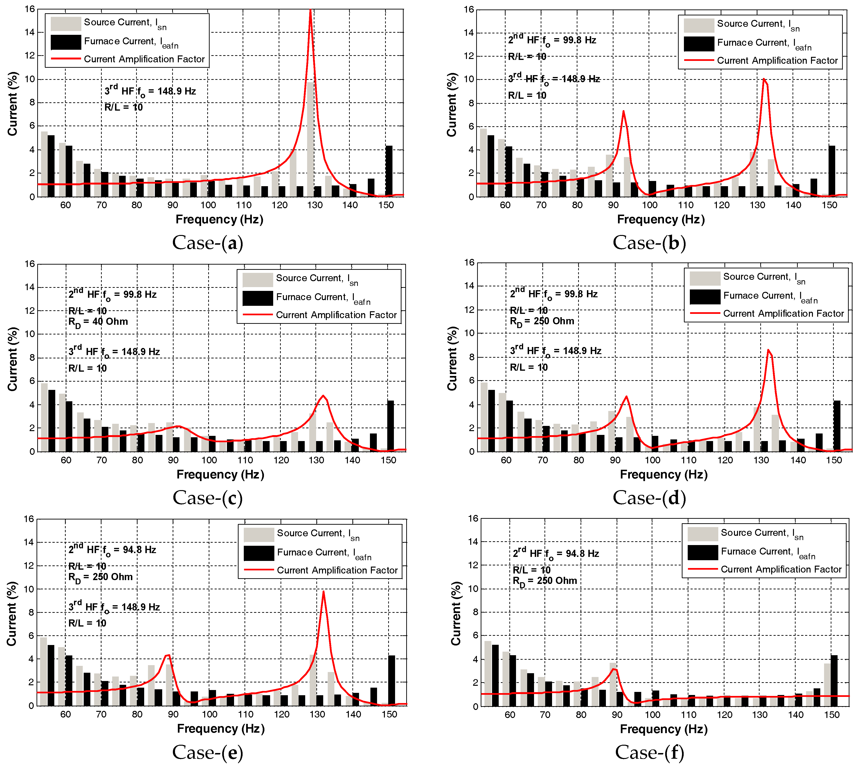
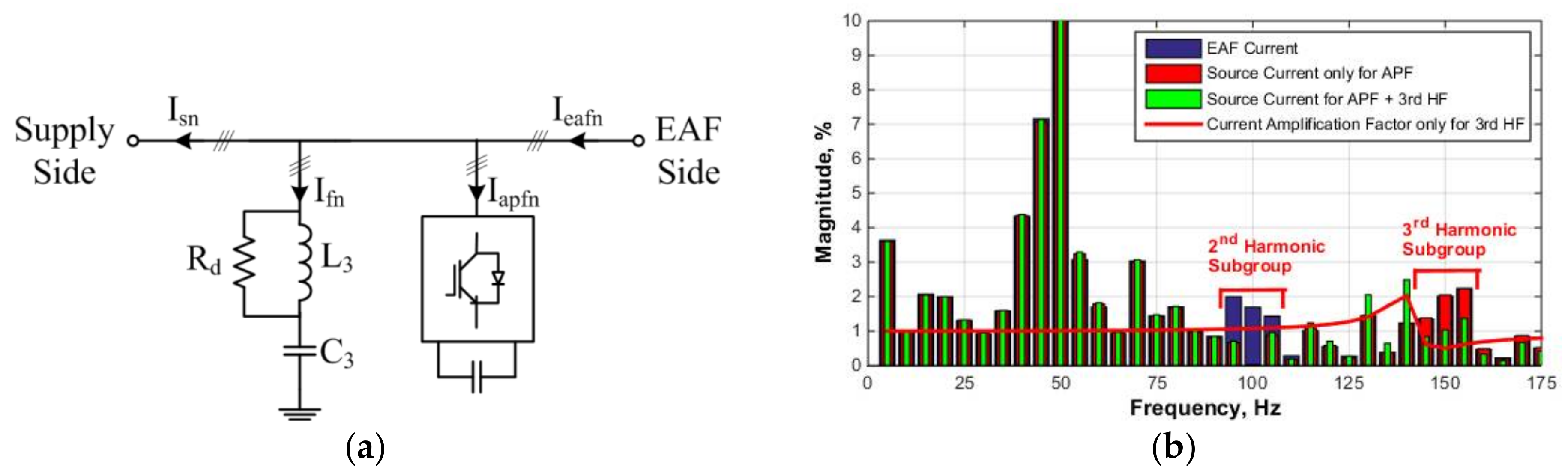
- Second harmonic subgroup reduction is computed for the harmonic spectrum given in Figure 12 and it is found to be 36.9% without affecting the neighboring interharmonic components by using the proposed APF topology. This is much better than the best cases for passive shunt harmonic filters given in Table 2, which are case-e and -f. Although 56.4 and 48.0% of the second harmonic subgroup of the EAF current are reflected to the supply-side for case-e and –f in Table 2, these topologies still amplify other interharmonic components, as shown in Figure 3.
6. Conclusions
Author Contributions
Conflicts of Interest
References
- Salor, O.; Gultekin, B.; Buhan, S.; Boyrazoglu, B.; Inan, T.; Atal, T.; Acik, A.; Terciyanli, A.; Unsar, O.; Altintas, E.; et al. Electrical Power Quality of Iron and Steel Industry in Turkey. IEEE Trans. Ind. Appl. 2010, 46, 60–80. [Google Scholar] [CrossRef]
- Srdic, S.; Nedeljkovic, M.; Vukosavic, S.N.; Radakovic, Z. Fast and Robust Predictive Current Controller for Flicker Reduction in DC Arc Furnaces. IEEE Trans. Ind. Electron. 2016, 63, 4628–4640. [Google Scholar] [CrossRef]
- Esfahani, M.T.; Vahidi, B. A New Stochastic Model of Electric Arc Furnace Based on Hidden Markov Model: A Study of Its Effects on the Power System. IEEE Trans. Power Del. 2012, 27, 1893–1901. [Google Scholar] [CrossRef]
- Hsu, Y.-J.; Chen, K.-H.; Huang, P.-Y.; Lu, C.N. Electric Arc Furnace Voltage Flicker Analysis and Prediction. IEEE Trans. Instrum. Meas. 2011, 69, 3360–3368. [Google Scholar] [CrossRef]
- Beites, L.F.; Mayordomo, J.G.; Hernandez, A.; Asensi, R. Harmonics, Interharmonics and Unbalances of Arc Furnaces: A New Frequency Domain Approach. IEEE Trans. Power Del. 2001, 16, 661–668. [Google Scholar] [CrossRef]
- Uz-Logoglu, E.; Salor, O.; Ermis, M. Online Characterization of Interharmonics and Harmonics of AC Electric Arc Furnaces by Multiple Synchronous Reference Frame Analysis. IEEE Trans. Ind. Appl. 2016, 52, 2673–2683. [Google Scholar] [CrossRef]
- Uz-Logoglu, E.; Salor, O.; Ermis, M. Real-time Detection of Interharmonics and Harmonics of AC Electric Arc Furnaces on GPU Framework. In Proceedings of the IEEE Industry Applications Society Annual Meeting, Cincinnati, OH, USA, 1–5 October 2017; pp. 1–8. [Google Scholar]
- White, R.S.; Dionise, T.J.; Baron, J.A. Design, Analysis, and Operation of the Electrical Distribution System for a Modern Electric Arc Furnace and Ladle Melt Furnace. IEEE Trans. Ind. Appl. 2010, 46, 2267–2275. [Google Scholar] [CrossRef]
- Gercek, C.O.; Ermis, M.; Ertas, A.; Kose, K.N.; Unsar, O. Design, Implementation, and Operation of a New C-Type 2nd Harmonic Filter for Electric Arc and Ladle Furnaces. IEEE Trans. Ind. Appl. 2011, 47, 1545–1557. [Google Scholar] [CrossRef]
- Akagi, H. Active Harmonic Filters. IEEE Proc. 2005, 93, 2128–2141. [Google Scholar] [CrossRef]
- De Almeida Carlos, G.A.; Jacobina, C.B. Series Compensator Based on Cascaded Transformers Coupled With Three-Phase Bridge Converters. IEEE Trans. Ind. Appl. 2017, 53, 1271–1279. [Google Scholar] [CrossRef]
- Teixeira, N.F.; Pinto, J.G.O.; Freitas, M.J.S.; Afonso, J.L. New Control Algorithm for Single-Phase Series Active Power Filter. Electr. Power Compon. Syst. 2015, 43, 1752–1760. [Google Scholar] [CrossRef] [Green Version]
- Tang, Y.; Loh, P.C.; Wang, P.; Choo, F.H.; Gao, F.; Blaabjerg, F. Generalized Design of High Performance Shunt Active Power Filter with Output LCL Filter. IEEE Trans. Ind. Electron. 2012, 59, 1443–1452. [Google Scholar] [CrossRef]
- Panigrahi, R.; Subudhi, B. Performance Enhancement of Shunt Active Power Filter Using a Kalman Filter-based H. Control Strategy. IEEE Trans. Power Electron. 2017, 32, 2622–2630. [Google Scholar] [CrossRef]
- Panigrahi, R.; Panda, P.C.; Subudhi, B. A Robust Extended Complex Kalman Filter and Sliding-mode Control Based Shunt Active Power Filter. Electr. Power Compon. Syst. 2014, 42, 520–532. [Google Scholar] [CrossRef]
- Narongrit, T.; Areerak, K.; Areerak, K. Adaptive Fuzzy Control for Shunt Active Power Filters. Electr. Power Compon. Syst. 2016, 44, 647–657. [Google Scholar] [CrossRef]
- Anjana, P.; Gupta, V.; Tiwari, H.; Gupta, N.; Bansal, R. Hardware Implementation of Shunt APF Using Modified Fuzzy Control Algorithm with STM32F407VGT Microcontroller. Electr. Power Compon. Syst. 2016, 44, 1530–1542. [Google Scholar] [CrossRef]
- Fereidouni, A.; Masoum, M.A.S. Shunt Active Power Filter Enhancement by Means of Frequency-locking Complex Adaptive Linear Combiner. Electr. Power Compon. Syst. 2016, 44, 2256–2270. [Google Scholar] [CrossRef]
- Ghamri, A.; Benchouia, M.T.; Golea, A. Sliding-mode Control Based Three-phase Shunt Active Power Filter: Simulation and Experimentation. Electr. Power Compon. Syst. 2012, 40, 383–398. [Google Scholar] [CrossRef]
- Suresh, D.; Singh, S.P. Type-2 Fuzzy Logic Controlled Three-level Shunt Active Power Filter for Power Quality Improvement. Electr. Power Compon. Syst. 2016, 44, 873–882. [Google Scholar] [CrossRef]
- Ngo, T.; Biricik, S.; Basu, M. A Self-tuning Grid Synchronization Method for Active Power Filter. Electr. Power Compon. Syst. 2016, 44, 1947–1957. [Google Scholar] [CrossRef]
- Wiebe, E.; Duran, J.L.; Acosta, P.R. Integral Sliding-mode Active Filter Control for Harmonic Distortion Compensation. Electr. Power Compon. Syst. 2011, 39, 833–849. [Google Scholar] [CrossRef]
- Boukezata, B.; Chaoui, A.; Gaubert, J.-P.; Hachemi, M. Power Quality Improvement by an Active Power Filter in Grid-connected Photovoltaic Systems with Optimized Direct Power Control Strategy. Electr. Power Compon. Syst. 2016, 44, 2036–2047. [Google Scholar] [CrossRef]
- Yilmaz, I.; Durna, E.; Ermis, M. Design and Implementation of a Hybrid System for the Mitigation of PQ Problems of Medium-Frequency Induction Steel-Melting Furnaces. IEEE Trans. Ind. Appl. 2016, 52, 2700–2713. [Google Scholar] [CrossRef]
- Durna, E.; Yilmaz, I.; Ermis, M. Suppression of Time-Varying Interharmonics Produced by Medium-Frequency Induction Melting Furnaces by a HAPF System. IEEE Trans. Power Electron. 2017, 32, 1030–1043. [Google Scholar] [CrossRef]
- Corasaniti, V.F.; Barbieri, M.B.; Arnera, P.L.; Valla, M.I. Hybrid Power Filter to Enhance Power Quality in a Medium-Voltage Distribution Network. IEEE Trans. Ind. Electron. 2009, 56, 2885–2893. [Google Scholar] [CrossRef]
- Xie, C.; Zhao, X.; Savaghebi, M.; Meng, L.; Guerrero, J.M.; Vasquez, J.C. Multi rate Fractional-Order Repetitive Control of Shunt Active Power Filter Suitable for Microgrid Applications. IEEE J. Sel. Top. Power Electron. 2017, 5, 809–819. [Google Scholar] [CrossRef]
- Akagi, H.; Kondo, R. A Transformerless Hybrid Active Filter Using a Three-Level Pulse width Modulation (PWM) Converter for a Medium-Voltage Motor Drive. IEEE Trans. Power Electron. 2010, 25, 1365–1374. [Google Scholar] [CrossRef]
- Testing and Measurement Techniques-General Guide on Harmonics and Interharmonics Measurements and Instrumentation for Power Supply Systems and Equipment Connected Thereto. IEC Std. 61000-4-7, 2002, 2.0 ed. Available online: https://webstore.iec.ch/preview/info_iec61000-4-7%7Bed2.0%7Den_d.pdf (accessed on 19 April 2018).
- Bollen, M.H.; Gu, I. Signal Processing of Power Quality Disturbances; Wiley-IEEE Press: Hoboken, NJ, USA, 2006; ISBN 978-0-471-73168-9. [Google Scholar]
- Gunther, E.W.; Mc Granaghan, M.F. Power measurements in distorted and unbalanced conditions-an overview of IEEE Trial-Use Standard 1459–2000. In Proceedings of the IEEE Power Engineering Society Summer Meeting, Chicago, IL, USA, 21–25 July 2002; pp. 930–934. [Google Scholar]
- Filipski, P.S. Polyphase apparent power and power factor under distorted waveform conditions. IEEE Trans. Power Del. 1991, 6, 1161–1165. [Google Scholar] [CrossRef]
- IEEE Standard Definitions for the Measurement of Electric Power Quantities Under Sinusoidal, Nonsinusoidal, Balanced, or Unbalanced Conditions. IEEE Std 1459-2010 2010. [CrossRef]
- Gerçek, C.O.; Ermis, M. Elimination of Coupling Transformer Core Saturation in Cascaded Multilevel Converter-Based T-STATCOM Systems. IEEE Trans. Power Electron. 2014, 29, 6796–6809. [Google Scholar] [CrossRef]
- Lam, C.-S.; Cui, X.-X.; Choi, W.-H.; Wong, M.C.; Han, Y.D. Minimum inverter capacity design for LC-hybrid active power filters in three-phase four-wire distribution systems. IET Power Electron. 2012, 5, 956–968. [Google Scholar] [CrossRef]
- Voltage Ratings of High Power Semiconductors. ABB Switzerland Ltd. Semiconductors: Lenzburg, Switzerland, 2013. Available online: https://library.e.abb.com/public/6f03cdd0f2264ff48f2992e62497dd5a/Voltage%20ratings%20of%20high%20power%20_%205SYA%202051NLay.pdf (accessed on 19 April 2018).
- Cetin, A.; Ermis, M. VSC-Based D-STATCOM with Selective Harmonic Elimination. IEEE Trans. Ind. Appl. 2009, 45, 1000–1015. [Google Scholar] [CrossRef]
- Ingram, D.M.; Round, S.D. A Fully Digital Hysteresis Current Controller for an Active Power Filter. Int. J. Electron. 1999, 86, 1217–1232. [Google Scholar] [CrossRef]
- Chen, C.; Cramer, A.M.; Liu, X. Average-value Modeling of Hysteresis Current Controlled Three-phase Inverters. Electr. Power Compon. Syst. 2016, 44, 693–700. [Google Scholar] [CrossRef]
- Tian, B.; Mao, C.; Lu, J.; Wang, D.; He, Y.; Zhou, B.; Zhang, J.; Chen, X. Seamless Transfer Control Strategy for Grid-Interactive Inverters. Electr. Power Compon. Syst. 2014, 42, 1587–1597. [Google Scholar] [CrossRef]
- Wu, F.; Feng, F.; Luo, L.; Duan, J.; Sun, L. Sampling Period Online Adjusting-Based Hysteresis Current Control Without Band with Constant Switching Frequency. IEEE Trans. Ind. Electron. 2015, 62, 270–277. [Google Scholar] [CrossRef]
- Davoodnezhad, R.; Holmes, D.G.; McGrath, B.P. A Novel Three-Level Hysteresis Current Regulation Strategy for Three-Phase Three-Level Inverters. IEEE Trans. Power Electron. 2014, 29, 6100–6109. [Google Scholar] [CrossRef]
- Malesani, L.; Mattavelli, P.; Tomasin, P. High-performance hysteresis modulation technique for active filters. IEEE Trans. Power Electron. 1997, 12, 876–884. [Google Scholar] [CrossRef]
- Lam, C.-S.; Wong, M.-C.; Han, Y.-D. Hysteresis current control of hybrid active power filters. IET Power Electron. 2012, 5, 1175–1187. [Google Scholar] [CrossRef]


| Frequency Hz | Case-0 Ieafn (%) | Case-(a) Isn (%) | Case-(b) Isn (%) | Case-(c) Isn (%) | Case-(d) Isn (%) | Case-(e) Isn (%) | Case-(f) Isn (%) |
|---|---|---|---|---|---|---|---|
| 95 | 1.16 | 1.50 | 3.34 | 1.99 | 2.90 | 0.34 | 0.33 |
| 100 | 1.32 | 1.81 | 0.19 | 1.29 | 0.41 | 0.75 | 0.66 |
| 105 | 1.00 | 1.48 | 0.55 | 0.87 | 0.57 | 0.79 | 0.63 |
| Source Second Harmonic Subgroup | Case-0 (%) | Case-a (%) | Case-b (%) | Case-c (%) | Case-d (%) | Case-e (%) | Case-f (%) |
|---|---|---|---|---|---|---|---|
| As a percentage of Fundamental Component | 2.02 | 2.78 | 3.39 | 2.53 | 2.98 | 1.14 | 0.97 |
| As a percentage of Furnace Second Harmonic Subgroup | 100 | 137.6 | 167.8 | 125.2 | 147.5 | 56.4 | 48.0 |
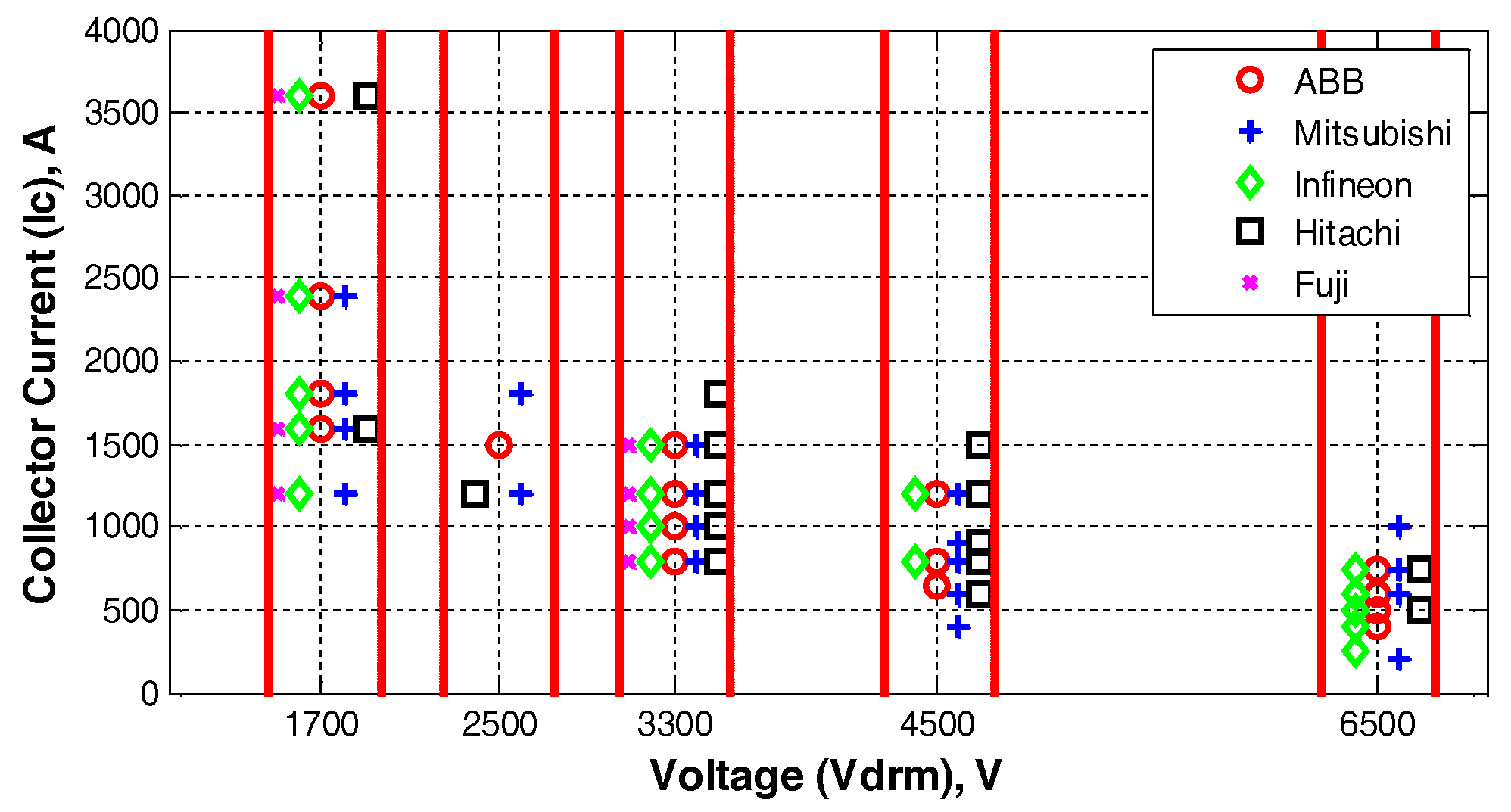
| IGBT Blocking Voltage (VDRM) | MAX DC Link Voltage (VDC) |
|---|---|
| 6500 V | 4000 V |
| 4500 V | 2800 V |
| 3300 V | 2000 V |
| 2500 V | 1500 V |
| 1700 V | 1000 V |
| HV IGBT | Optimum DC Link Voltage VDC | Turns Ratio N | Required Transformer Line Current on the Secondary (A) | Minimum Number of APF Units M | |
|---|---|---|---|---|---|
| VDRM (V) | IC (A) | ||||
| 6500 | 1000 | 4000 | 13.3 | 4522 | 5 |
| 4500 | 1500 | 2800 | 19.0 | 6460 | 5 |
| 3300 | 1700 | 2000 | 26.6 | 9044 | 6 |
| 2500 | 1700 | 1500 | 35.5 | 12,070 | 8 |
| 1700 | 3600 | 1000 | 53.2 | 18,088 | 6 |
© 2018 by the authors. Licensee MDPI, Basel, Switzerland. This article is an open access article distributed under the terms and conditions of the Creative Commons Attribution (CC BY) license (http://creativecommons.org/licenses/by/4.0/).
Share and Cite
Durna, E.; Gerçek, C.Ö.; Salor, Ö.; Ermiş, M. Suppression of the Second Harmonic Subgroup Injected by an AC EAF: Design Considerations and Performance Estimation of a Shunt APF. Electronics 2018, 7, 53. https://doi.org/10.3390/electronics7040053
Durna E, Gerçek CÖ, Salor Ö, Ermiş M. Suppression of the Second Harmonic Subgroup Injected by an AC EAF: Design Considerations and Performance Estimation of a Shunt APF. Electronics. 2018; 7(4):53. https://doi.org/10.3390/electronics7040053
Chicago/Turabian StyleDurna, Emre, Cem Özgür Gerçek, Özgül Salor, and Muammer Ermiş. 2018. "Suppression of the Second Harmonic Subgroup Injected by an AC EAF: Design Considerations and Performance Estimation of a Shunt APF" Electronics 7, no. 4: 53. https://doi.org/10.3390/electronics7040053