Article

A Novel Supercapacitor/Lithium-Ion Hybrid Energy System with a Fuzzy Logic-Controlled Fast Charging and Intelligent Energy Management System

1
School of Electrical Engineering, Pusan National University, Busandaehak-ro 63 beon-gil, Geumjeong-gu, Busan 46241, Korea
2
School of Electrical Engineering and Computer Science, National University of Sciences and Technology, Islamabad 44000, Pakistan
3
Department of Computer Engineering, Pusan National University, Busan 46241, Korea
*
Author to whom correspondence should be addressed.
Electronics 2018, 7(5), 63; https://doi.org/10.3390/electronics7050063
Submission received: 25 April 2018 / Revised: 1 May 2018 / Accepted: 2 May 2018 / Published: 4 May 2018
(This article belongs to the Special Issue Hardware and Architecture)

Abstract

:
The electric powered wheelchair (EPW) is an essential assistive tool for people with serious injuries or disability. This manuscript describes the validation of applied research for reducing the charging time of an electric wheelchair using a hybrid electric system (HES) composed of a supercapacitor (SC) bank and a lithium-ion battery with a fuzzy logic controller (FLC)-based fast charging system for Li-ion batteries and a fuzzy logic-based intelligent energy management system (FLIEMS) for controlling the power flow within the HES. The fast charging FLC was designed to drive the voltage difference (Vd) among the different cells of a multi-cell battery and the cell voltage (Vc) of an individual cell. These parameters (voltage difference and cell voltage) were used as input voltages to reduce the charge time and activate a bypass equalization (BPE) scheme. BPE was introduced in this paper so that the battery operates within the safe voltage range. For SC/Li-ion HES, the FLIEMS presented in this paper controls the bi-directional power flow to smooth the power extracted from Li-ion batteries. Moreover, a dual active bridge isolated bidirectional DC converter (DAB-IBDC) was used for power conversion. The DAB-IBDC presented in this paper has the characteristics of galvanic isolation, and high power conversion efficiency compared to the conventional converter circuits due to the reduced reverse power flow and current stresses.

1. Introduction

Electric powered wheelchairs (EPW) are quite popular among differently disabled people. Reducing the charging time to as low as possible has been a long desire and recent research emphasis. The prevailing energy source used for EPW is the lithium-ion (Li-ion) battery. Li-ion batteries are flexible, require less maintenance, offer higher energy density (typically in the range of 115 to 165 Wh/kg), and have a low self-discharge rate (approximately 5% per month) [1]. On the other hand, Li-ion batteries have a low power density and slow charging rates (taking several hours for charging). Once the battery is discharged and the battery voltage drops below a safe limit, the EPW cannot move, which prevents differently disabled people from moving freely and performing their daily activities. Special charging circuits are required for voltage balancing to alleviate this limitation [2,3]. To overcome these limitations of conventional batteries system for EPW, this paper introduces an approach using supercapacitors (SCs) in parallel with Li-ion batteries.
SCs are electrochemical capacitors with double layers, having high power densities. SCs have rapid charging and discharging ability and can achieve a higher power density. Moreover, there is no need for chemical action for the operation and lifespan of many thousands of cycles, which is equivalent to a lifetime of 10 to 12 years [4,5]. Nevertheless, SCs have a low power-to-weight ratio and low energy density compared to the high self-discharge rate and current battery technology, so they are not ideal as the only source of electric power for electric wheelchairs [6,7,8].
A hybrid energy storage system has attracted attention in recent years for on-ground transportation systems and many other applications [9,10,11,12,13]. The use of a SC hybrid with Li-ion batteries for the uninterrupted movement of an EPW, which will not only minimize the charging time, but will also facilitate the charging process while moving back from some heights using a regenerative mechanism. The performance of these hybrid electric systems mainly depends upon the energy controlling mechanism and the system assembly selection. Among all these assemblies, passive, semi-active, and active structures have been studied in [14]. In passive structures, SCs banks are connected in parallel to the Li-ion batteries and the power distribution between them depends simply on their internal resistance. SCs and passive battery structures are low-cost and easy to manufacture. On the other hand, control of the power flow is always challenging. In active architectures, both the SCs and batteries are connected to a direct current (DC) bus by two full-sized bi-directional DC/DC converters controlled independently [15]. In semi-active structures, the Li-Po battery or supercapacitor is attached to the DC bus with a bi-directional DC/DC converter as the controlled element, and this structure offers a tradeoff among the control strategies and complexity [16]. An EPS–algorithm-based DAB converter for charging a SC bank under pulsed load conditions was proposed [17]; the SC acts as a filter that relieves the peak stresses on the battery. Multi-input converters (MICs) are prominent in DC-DC converters used in hybrid energy storage systems (HESSs) because of its low cost [18].
HESSs and battery/SCs have been studied in detail for use in electric vehicles (EVs); hybridization of this kind might meet the requirements of an EV. Moreover, due to the low energy density, it is always desirable to use SCs effectively in a HES, which is why, in a HEES, an energy management strategy (EMS) and power distribution unit play crucial roles. In a previous study [19], based on Markov random prediction, a fuzzy-logic energy management was considered for a semi-active HESS structure. The power management strategy in [19] uses the current electric power demand and the predicted electric power demand; to distribute the electrical power between the battery bank and the SC bank. Battery bank power is limited to a certain range using this scheme. Optimization-based EMSs artificially design a cost function with limitations and solve its minimum online through different types of algorithms: convex optimization (CVX), dynamic programming (DP), model predictive control (MPC), or some evolutionary algorithms [20,21]. The method presented in [21] is based on a combination of deterministic dynamic programming (DP) and convex optimization, the method yields a global optimum. In this work, real-time implementable previewing strategies (utilizing model predictive control (MPC) and dynamic programming (DP)) are applied to a hybrid commercial vehicle’s results while returning the solution in much less time than the conventional DP method. In parallel, a SC with a Li-ion battery creates a hybrid energy storage that supports a higher discharge current because of the high-power density of the SC [22], which reduces the impact of the rate capacity effect. The EMS examined in [23] presented an inflexible and effective solution to the energy management problem; the control principle is defined by this method via the given rules for the operation modes of the utilized converter. The EMSs given in [24,25,26] aim to protect batteries from sudden load changes based on a frequency decoupling approach. The advantage of the FLC is that it does not require an exact mathematical model or information of the HESS. References [27,28] examined the FLC can be utilized fully in an EMS or combined with other methods, such as a neural network and wavelet decomposition, as reported in [29,30]. The fuzzy logic controller (FLC) is designed in [31] to shorten the charge line using the battery protection cell voltage and the voltage difference between each battery cell, and to ensure that the battery operates within the safe voltage range. Genetic-neuro-fuzzy controllers for a PID controller is proposed and tested in [32] while the results in [33] show the robustness of this PID controller for industrial applications due to its optimal time response and good overshoot values. An intelligent battery equalization scheme based on fuzzy logic control is presented in [34] to adaptively control the equalizing process of series-connected lithium-ion batteries and to design a ripple-free converter for improving the input current distortion of the battery charge supply power system.
A previous study [35] presented a SC/HESS/battery through a novel MIC topology for EVs; in this research, a rule-based EMS was used to charge SCs during regenerative braking and the battery power during propulsion. This method was effective, but it had two serious disadvantages: it did not limit the rate-of-charge battery power and it did not consider the state-of-charge. Based on the literature survey it is necessary to design an EMS in which the battery/SC HESS will control overcharging and SC/battery currents during the output power peak. With respect to the above issues, this paper also presents a fuzzy logic-based intelligent energy management system (FLIEMS) to determine the effect of battery/SC hybridization on the battery output power. The three main objectives of the paper are as follows: (1) a fuzzy logic-based fast charging scheme was designed for Li-ion batteries so that an electric wheelchair can move freely with less concern regarding the long wait for recharging; (2) an intelligent power management was designed for the SC-Li HES to effectively utilize the power from the SC-Li during charging, discharging, and regenerative modes, which was achieved by designing a fuzzy logic-based intelligent energy management system with a rate limiter for lithium ions. The presented EMS aimed to regulate the state of charge of super capacitor (SOCSC) using the developed FLC and the battery power peak was reduced using a rate limiter; and (3) a dual active bridge converter system was designed to facilitate the charge/discharge process during different modes of wheelchair operation. The working DAB converter designed in this paper was based on an EPES to offer easier power conversion than those conventional algorithms. The remainder of the paper is organized in three sections. Section 2 provides the theoretical background and components for the design of the proposed HES system and experimental set up for the proposed study. Section 3 discusses the results obtained from the study and reports the conclusions of the overall research.

2. Materials and Methods

2.1. Methodology

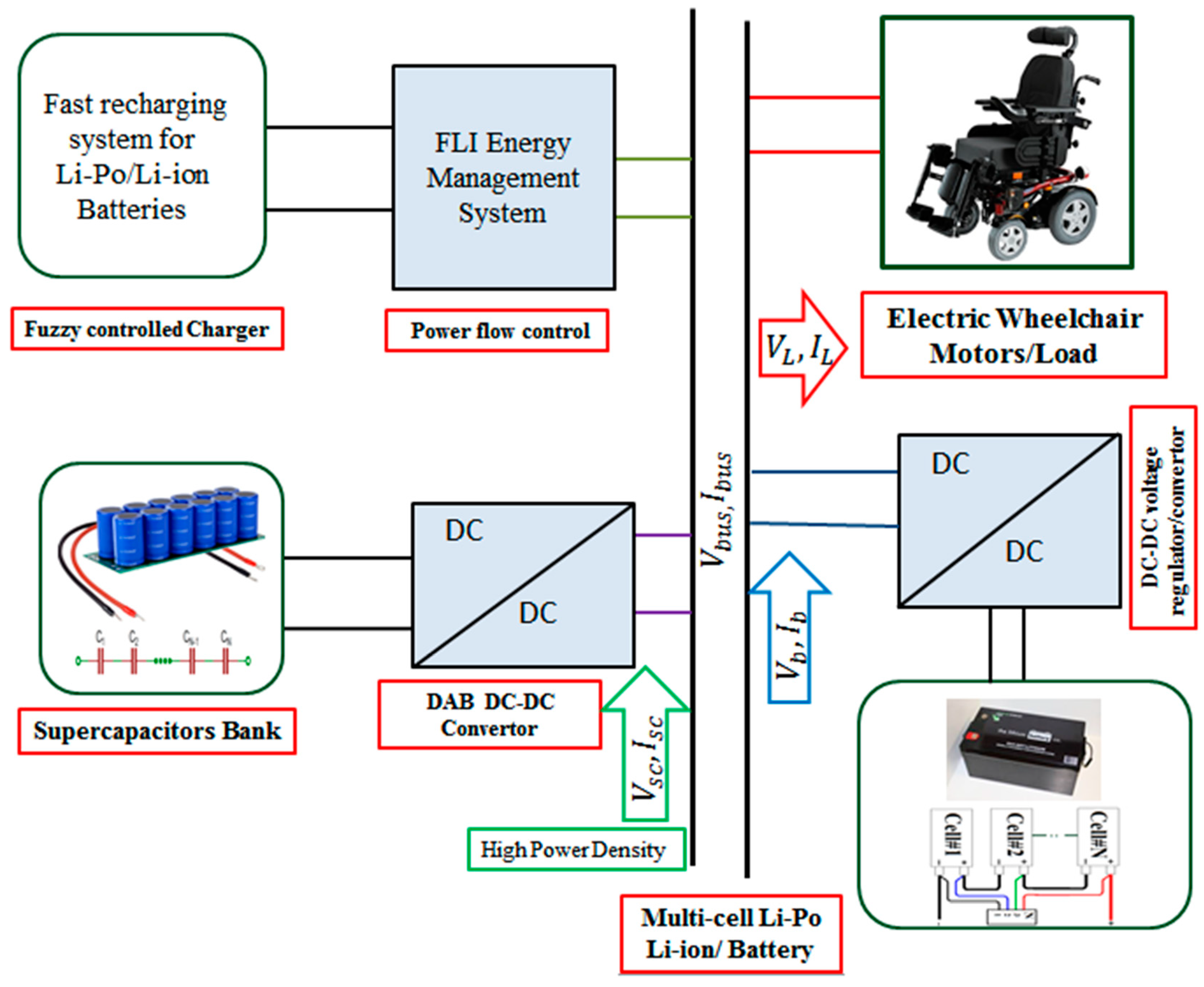
2.1.1. An Overview of the Proposed HES

This section provides a theoretical background for mathematical modeling, design parameters, and consideration of the components of the proposed HES for an EPW. The EPW consumes different amounts of power during its movement and uses some nominal power when moving on a planned path. The EPW consumes more power than normal when climbing and can save some energy when moving down from some heights. Therefore, based on the different amount of power required during the different modes of operation, this study developed a fuzzy-controlled energy management system that keeps a record of the power requirements and decides when to use the SCs, when to use the Li-ion batteries, and when to use them both in a very safe manner. Conventional charging (CC-CV charging) is replaced with the FLC-based rapid charging method proposed in this paper. Figure 1 outlines the proposed HES for EPW. As Li-Po batteries have a high energy density and SCs have a high-power density, it would be best to formulate a hybrid power source comprised of both Li-ion batteries and SC. The summations of a SC bank and Li-ion currents (i.e.,   I s c and I b ) contribute to the load current ( I L ) and bus current ( I b u s ). The SC bank voltage ( V s c ) is regulated using the DAB-IBDC (DAB) converters proposed in this paper. Figure 1 provides an overview of the total proposed power system that is explained in Section 2.1.2.

2.1.2. Components of the Suggested Fast-Charging Li-SC HES

A detailed overview of the components along with their working mechanism is given below.

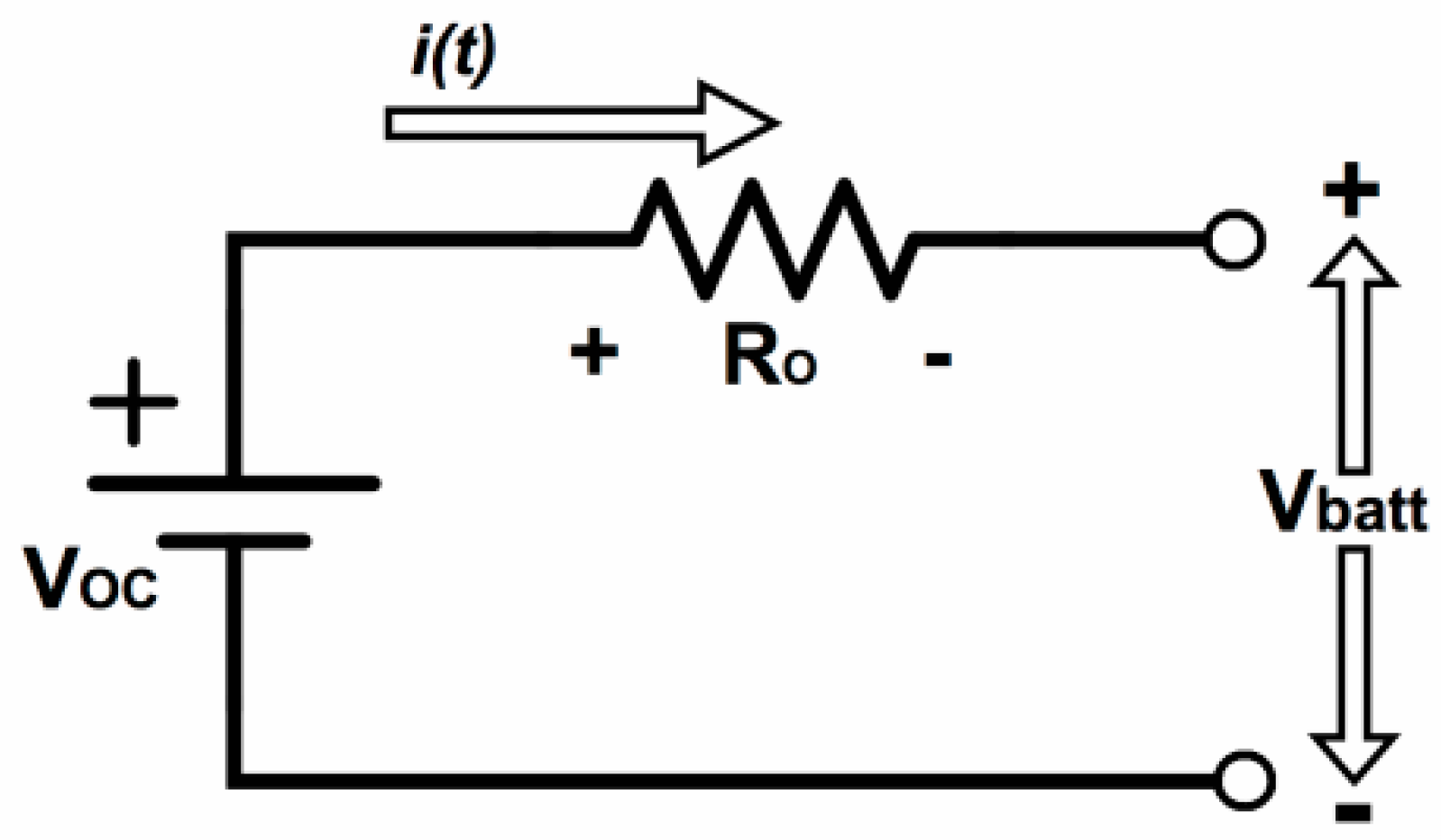
2.1.2.1. Multi-Cell Lithium-Ion Batteries

Lithium-ion batteries are commonly used in portable electronics, but are now being used in large-scale applications, such as electric vehicles and grid-connected systems. Li-ion batteries offer lower weight, volume, temperature sensitivity, and maintenance. Lithium-ion battery packs have a longer life than other types, such as lead acid, because of the higher round-trip efficiency than many options [36]. When choosing a battery for an EPW, it is important to consider the life and maintenance. The battery modeling approaches rely on the desired details in the model. The equivalent circuit model includes resistors connected in series with a constant voltage source, as shown in Figure 2 [37]. The equivalent circuit can exhibit simple, dynamic, and stable state behaviors [38].
In Figure 2, the internal dynamic current (A) of the battery is represented by i ( t ) , the internal ohmic resistance (ohms) of the battery is represented by R o , the output voltage of the battery is represented by V b a t t , and the input voltage of the battery is represented by Voc:
V o c = V b a t t i ( t ) R o  
Typically, the voltage of Li-ion single cell ranges from 3–4 V and need a large number of cells connected in series and parallel to increases the output voltage and current as per desired application, however, doing so reduces the charging efficiency as increase in number of cells also leads to a large unbalancing in voltage and, as a result, an increase in charging time occurs. A special charging circuit is required to solve this problem. A detail of our designed FLC charger for Li-ion batteries is provided in Section 2.1.2.3.

2.1.2.2. SC Bank

Compared to current battery technologies, SCs have a low power-to-weight ratio and low energy density. In contrast, SCs have rapid charging and discharging capability at high output densities, giving the EPW the fastest charging and discharging rates at high power densities when used as a component of a hybrid energy system and climbing high altitudes and climbing back from a height on some slopes. SCs have rapid charging and discharging ability and a higher power density; these features helps the electric wheelchair use a component of the hybrid energy system and utilize its rapid charging and discharging with a higher power density while climbing some heights for moving back from a height with some slopes. The selection of SC for EPW is based on three parameters: SCs voltage, capacitance, and energy storage capacity and SCs losses. The rated voltage SC module needs to be as close as possible to the DC bus voltage. When the DC bus voltage is a maximum (the drive is braking), the supercapacitor is charged. The supercapacitor rated voltage V s c max is recommended to follow Equation (2) [39]:
V s c m a x   V b u s m a x  
The minimum operating voltage for a supercapacitor is determined by the DC-DC converter current capability power P o and I c m a x :
V s c m i n P o I c m a x  
Energy storage capacity of the SC can be calculated as:
E C =   C o 2 ( V s c m a x 2 V s c o 2 ) + 2 3 K c   ( V s c m a x 3 V s c o 3 )  
where V s c m a x is the SC maximum working voltage while C 0 represents the electrostatic capacitance of the capacitor and V s c o is initial voltage of SC. K c is coefficient that represents the effects of diffused layer of the SC.
The initial capacitance C 0 for the given coefficient and energy EB given by Equations (5) and (6) respectively:
C 0 = ( E B 2 3 K c ( V s c m a x 3 V s c i n 3 M ) ) 2 ( V s c m a x 2 V s c i n 2 M )
where V s c i n M is intermediate voltage of SC bank. The braking energy E B is given by:
E B = η B 0 T B P o ( t ) d t
where ηB is the efficiency of the whole conversion system, including the drive converter, the motor, the DC-DC converter and SC efficiency. Power P 0 ( t ) is the drive shaft power and T B is the braking time [36].
The energy available for the ride through of SC is given by:
E R T = C 0 2 ( V s c i n M 2 V s c m i n 2 ) + 2 3 K c ( V s c i n M 2 V s c m i n 3 )
The ride-through energy ( E R T ) that SC bank can deliver to the drive system during power interruption is given by relation:
E R T = E R T = 1 η M 0 t R T P o ( t ) d t
where t R T is the ride-through time; and η M is the efficiency of the whole system which depends upon the internal resistance of the SC bank and drive shaft power P 0 ( t ) .
It is not recommended to discharge all the energy of the supercapacitor than that needed to support them. Therefore, the minimum voltage ratio should be fixed and the discharge ratio can be found using the following relation:
% d = V s c m i n V s c m a x × 100
The depth of discharge ( D O D ) can be written:
D O D = ( 100 d ) = 100 ( 1 V s c m i n V s c m a x )
While selecting for any EV it is important to compute power losses for SC. Assuming that the SC is a linear capacitor (KC ≅ 0) and neglecting the internal resistance R C 0 , one can find the SC charging current as:
i c o = P c o C o C o V s c m i n 2 + 2 P C 0 ( t ) C h a r g i n g
i c o = | P c o | C o C o V s c o 2 2 P C 0 ( t ) D i s c h a r g i n g
where the V s c o is the initial voltage. The SC charging/discharging power P C 0 is the constant [40].
The power losses SC are computed as under:
P c R C o P C 0 2 { C o C o V s c m i n 2 + 2 P C 0 ( t ) C h a r g i n g C o C o V s c o 2 2 P C 0 ( t ) d i s c h a r g i n g }

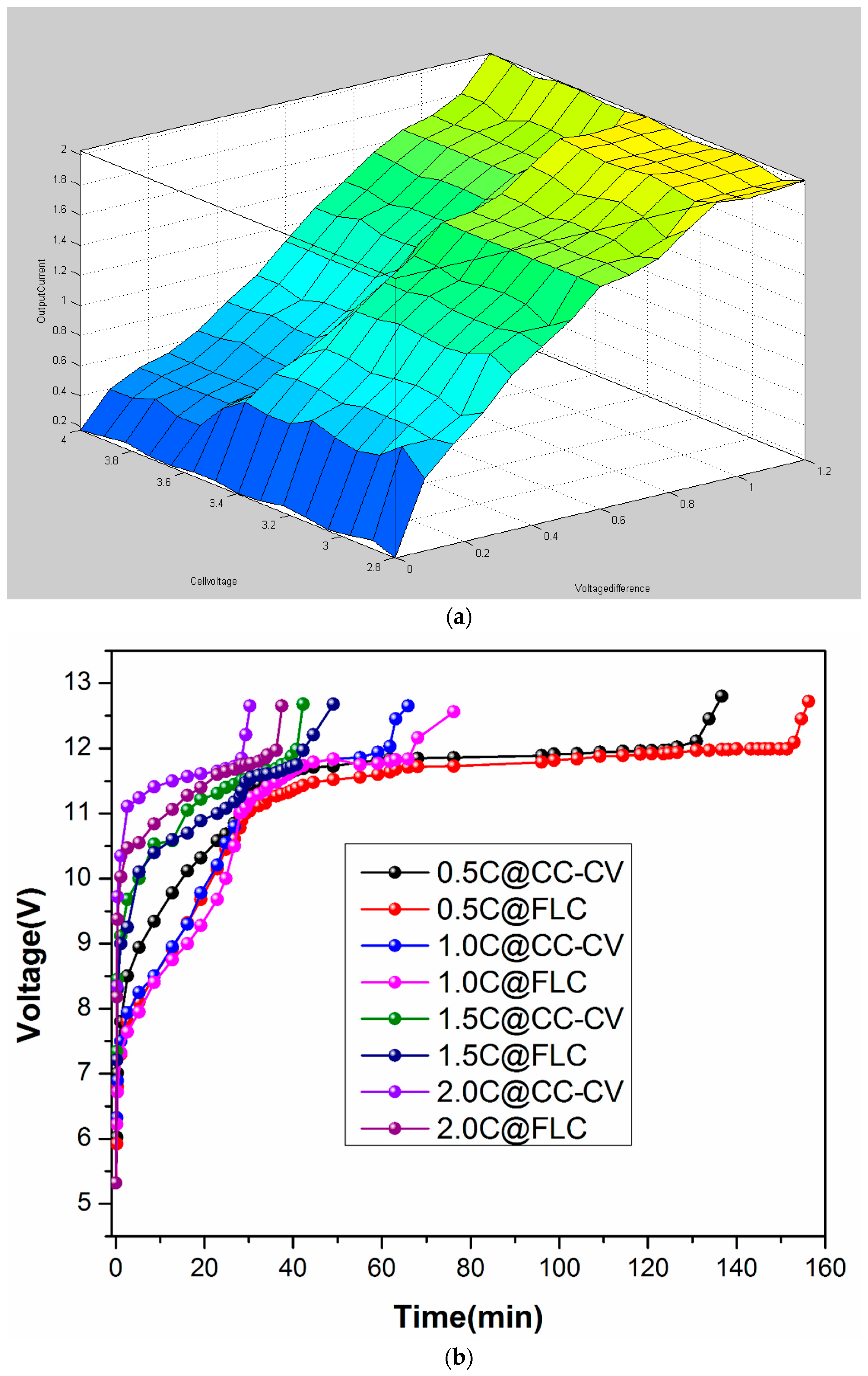
2.1.2.3. FLC Fast Charger Li-Po/Li-Ion Batteries

Li-ion batteries have very intricate nonlinear chemistry, and because the FLC does not need to control the precise mathematical model, an FLC adaptive method has been developed to control the battery cells. The charging time increases due to misbalancing voltages during charging time. The charging efficiency can be improved using a FLC to control the current in the CC-CV section. In this paper, we proposed a bypass equalization (BPE) technique controlled by the LC controller (see Figure 3). The BPE scheme is used for cell voltage balancing in multi-cell battery systems. Figure 3 presents the BFE algorithm for intelligent charging system arrays for the BPE method. The proposed intelligent charging system can reduce the charging time based on the fuzzy control rule ensuring that each cell of the battery string operates within a safe voltage range.
The FLC limits the charging current according to the discrete cells’ voltage differences and the cell voltage. Five linguistic variables are used to describe the FLC membership function, i.e., very small, small, medium, large, and very large. As presented in Figure 3, the control rules are collected by the rule base that describes the experience and knowledge of the battery equalization control in the fuzzy set. The de-fuzzifier is then used to convert the fuzzy linguistic inference results into the corresponding output. The control effort is the required fuzzy controlled output current as elaborated in Figure 3.

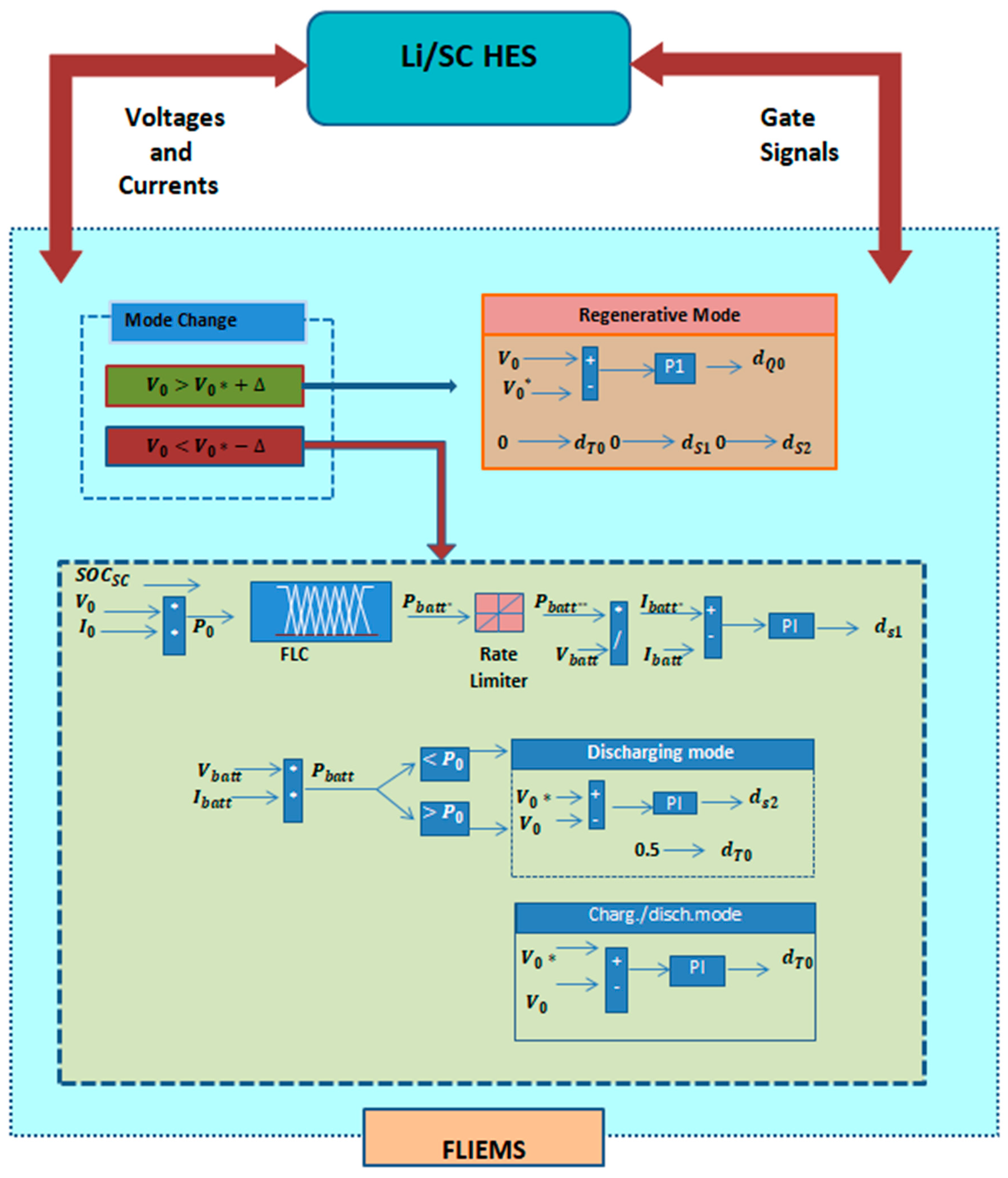
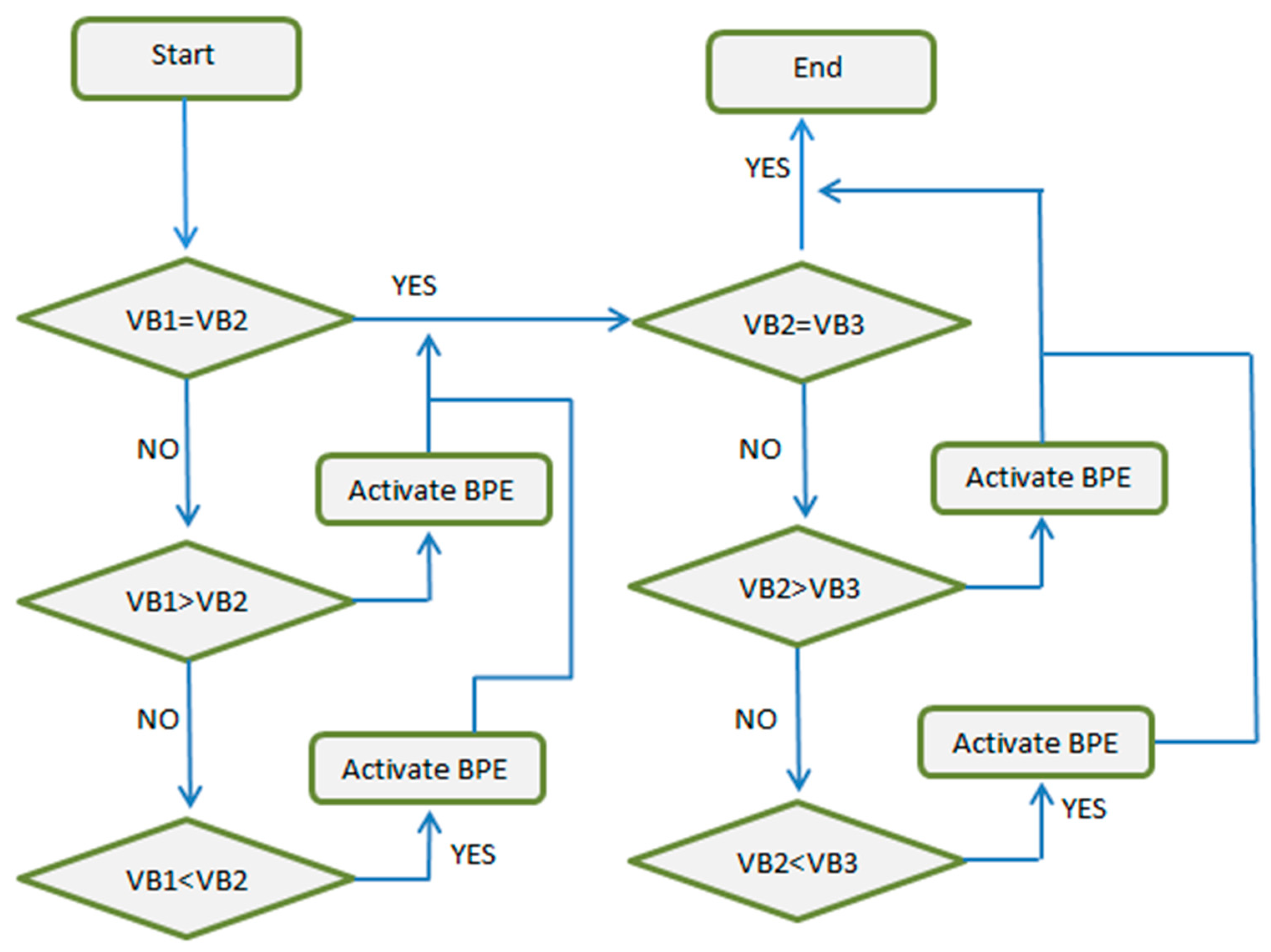
2.1.2.4. Intelligent Energy Management System Based on Fuzzy Logic

Figure 4 shows a detail working of the proposed FLIEMS. The EMS first decides the mode of operation by reading and analyzing the output voltage. The amount of power required for the motor is determined by the power available from the Li-ion battery and the SOCSC for the FLIEMS. To control the SOCSC at a reference value the battery reference power is determined by the FLC. In order to supply the desired demand, this value should be determined and the available braking energy to be captured has sufficient capacity should be ensured. To smooth the battery power profile, the rate limiter defines the slew rate of the reference battery power. Finally, the battery current is tuned utilizing a proportional integral (PID) controller to acquire the required battery power. The suggested control strategy selects the discharge mode or the charge mode by associating the battery with the output power level: the discharge mode is activated if the battery power is lower than the output power. Otherwise, the charge/discharge mode is enabled. For implementation of the FLIEMS specific attention should be given to battery chargers to control the gradual changes in the charging and assigning functions of the battery. As reported in [41], increasing d T o (the duty cycle of time) extends the input voltage range of the converter; the efficiency increases with increasing switch stress.
Furthermore, for the discharging mode, a reasonable d T o of 0.5 is set. In addition, to regulate the DC bus for controlling the power of the SC, as well as charging and discharging modes, PI controllers are used. On the contrary, if the output voltage increases, the charging mode will be activated as regenerative braking energy is sensed. d Q o is adjusted by another PI controller for the DC bus direction in the charging mode. The overall mode determination methodology is presented in Figure 5, where Δ is the considered voltage level. The FLC is defined by two input member functions: SOCSC (SOC of SC) and P o . Three input member functions: high (H), medium (M), and low (L), define the SOCSC. Four input membership functions for P o are considered. The output membership function, Pbat * high (V), has six output membership functions: very high (VH), high (H), medium (M), low (L), very low (VL), and very, very low (VVL). The reference of the battery power is obtained using a defuzzification technique based on defined membership functions and the rule base.

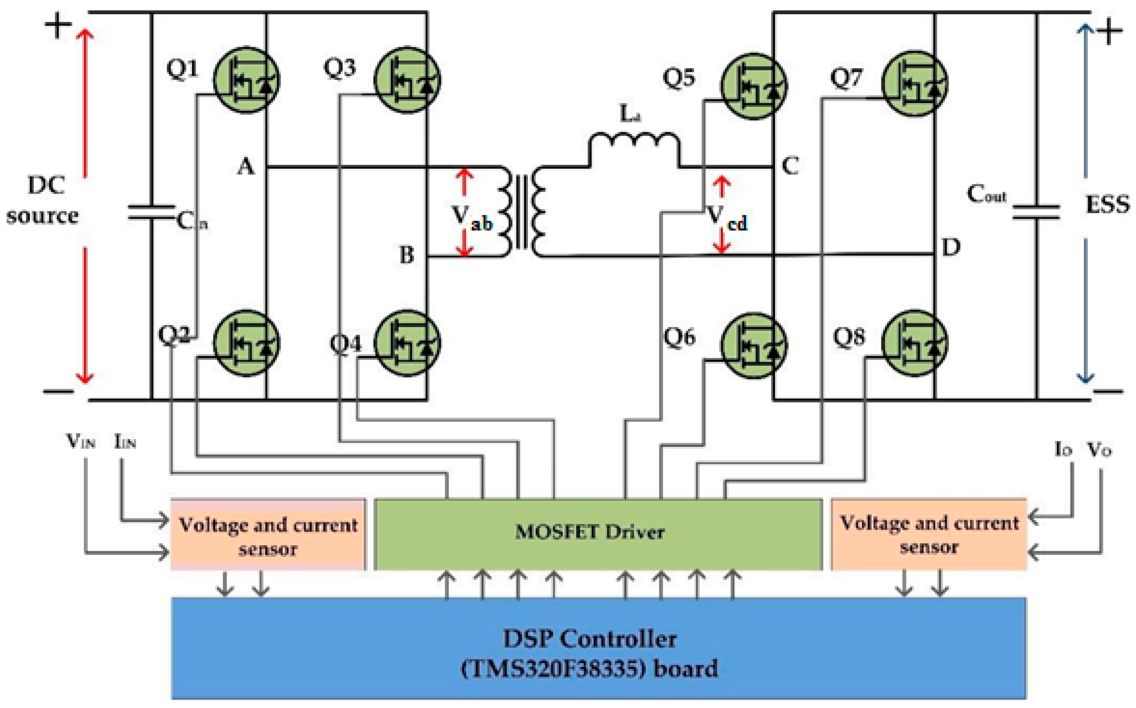
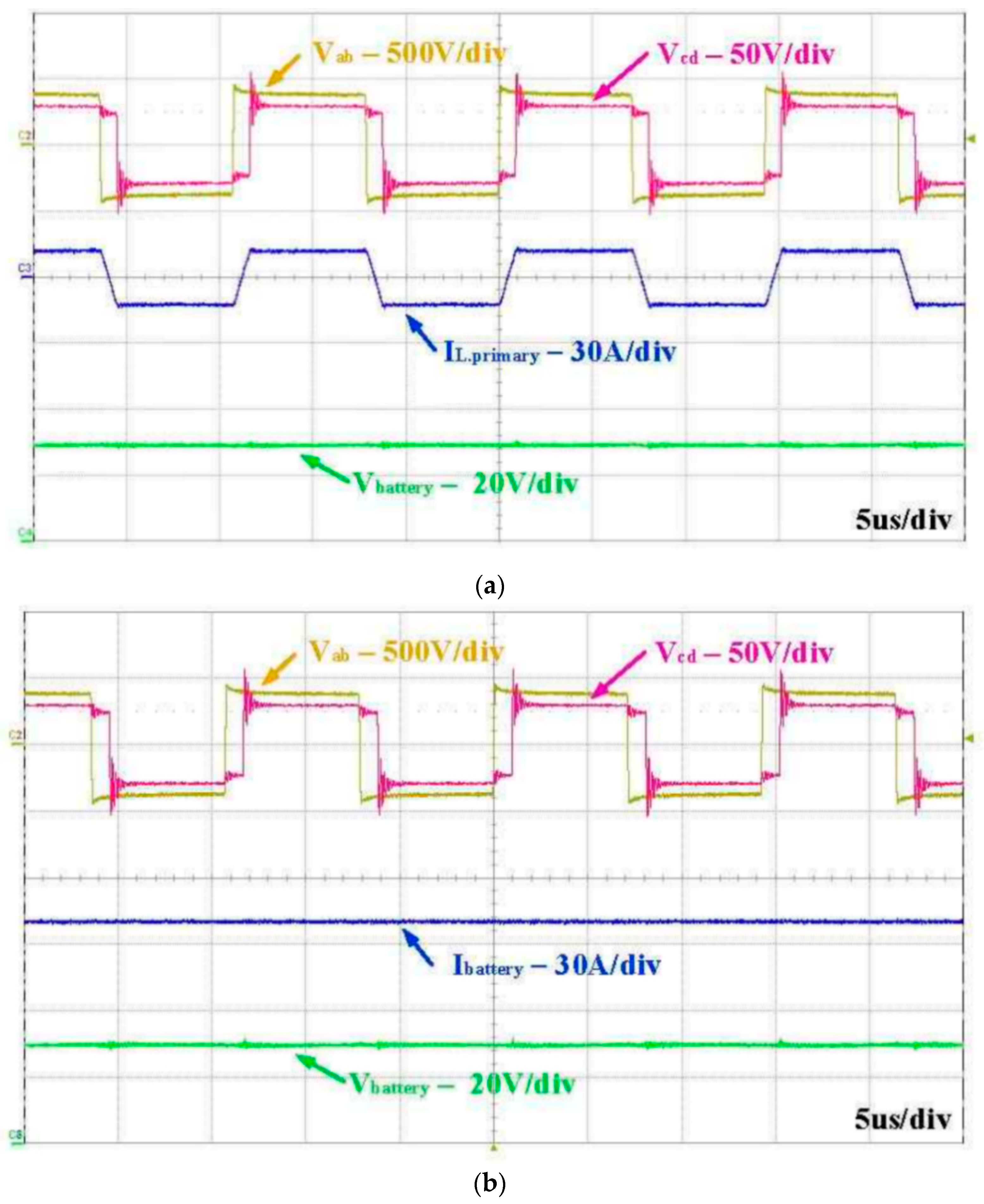
2.1.2.5. ESPS Controlled DAB-IBDC Converter

Figure 5 shows complete assembly for the DAB IBDC converter with switches, transformer, drivers, sensor, and DSP controller. The DAB DC-DC converter mainly contributes in application-related power electronics, such as semiconductor transformer electric vehicles and battery energy storage, due to its distinguishing feature of electrical isolation, high transmission efficiency, high power density, and bidirectional flow. The design of a high-frequency transformer, T, is mainly associated with bridges, such as the primary H-bridge consisting of Q1 to Q4, the H-bridge from Q5 to Q8, and the secondary bridge from Q1 to Q4. The inductor ‘L’ is the transformer primary side leakage inductance and harmonizing inductance. V1 and V2 are primary and secondary side voltages. The winding ratio of the transformer is set to 1; if not so, there can be back current flow from secondary on the primary side [42,43], due to which n = 1 was used during our analysis. Figure 6 illustrates the resulting curve of the DAB-IBDC using ESPS control, where d is the phase shift ratio between the primary and secondary voltages and T is the half switching period of the isolated high-frequency transformer having a value of d between ‘0′ and ‘1′ [44]. The square-shaped wave from Vab and Vcd were observed, and due to the inductance in the converter circuit association among the two voltages was observed. The primary voltage will not always be in phase with the primary current because it passes through the inductor. Based on the waveform IL the average current of the leakage inductor is derived. At inductor L mismatching between Vab and Vcd occurs, and at inductor current IL during switching of t1 and t2.

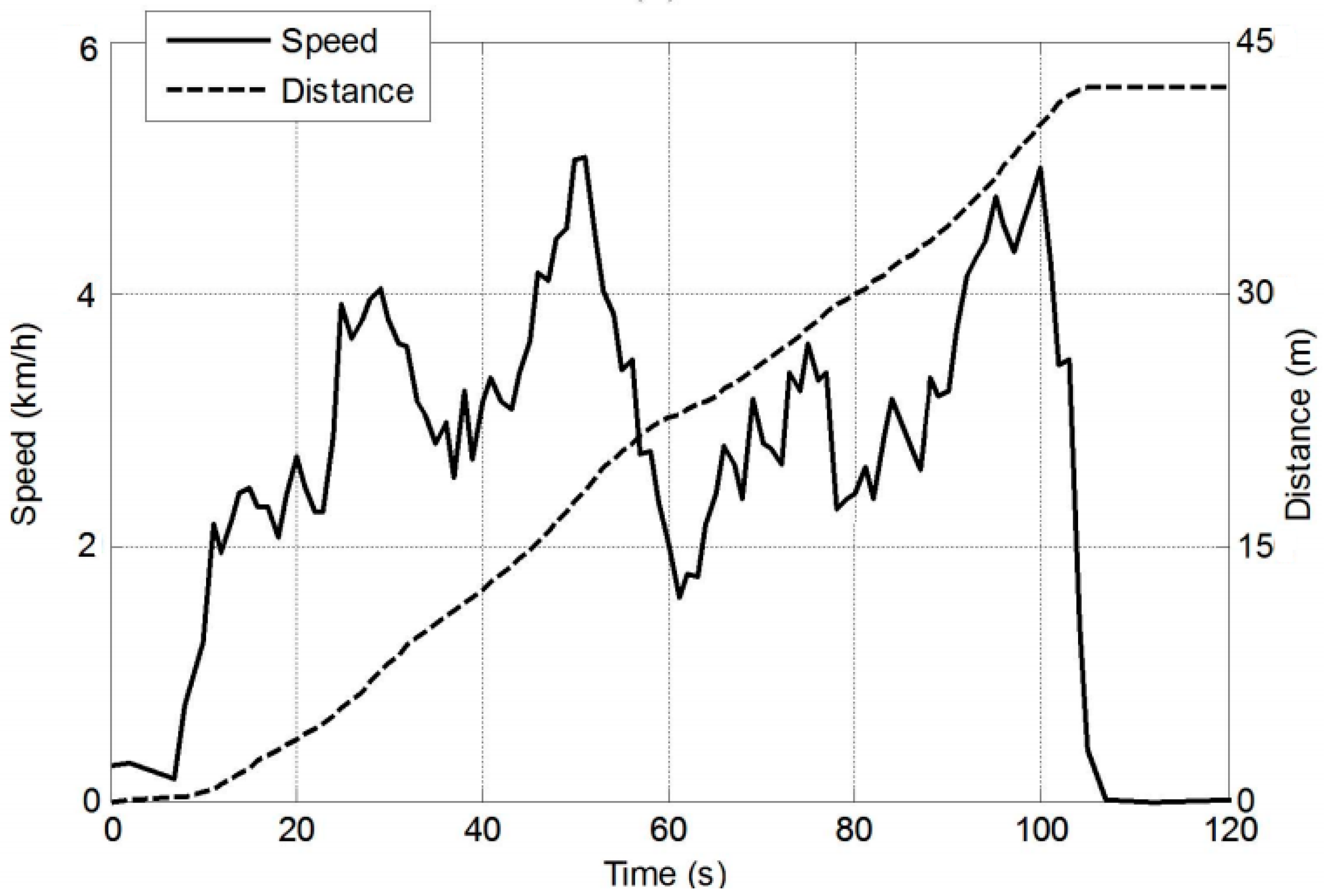
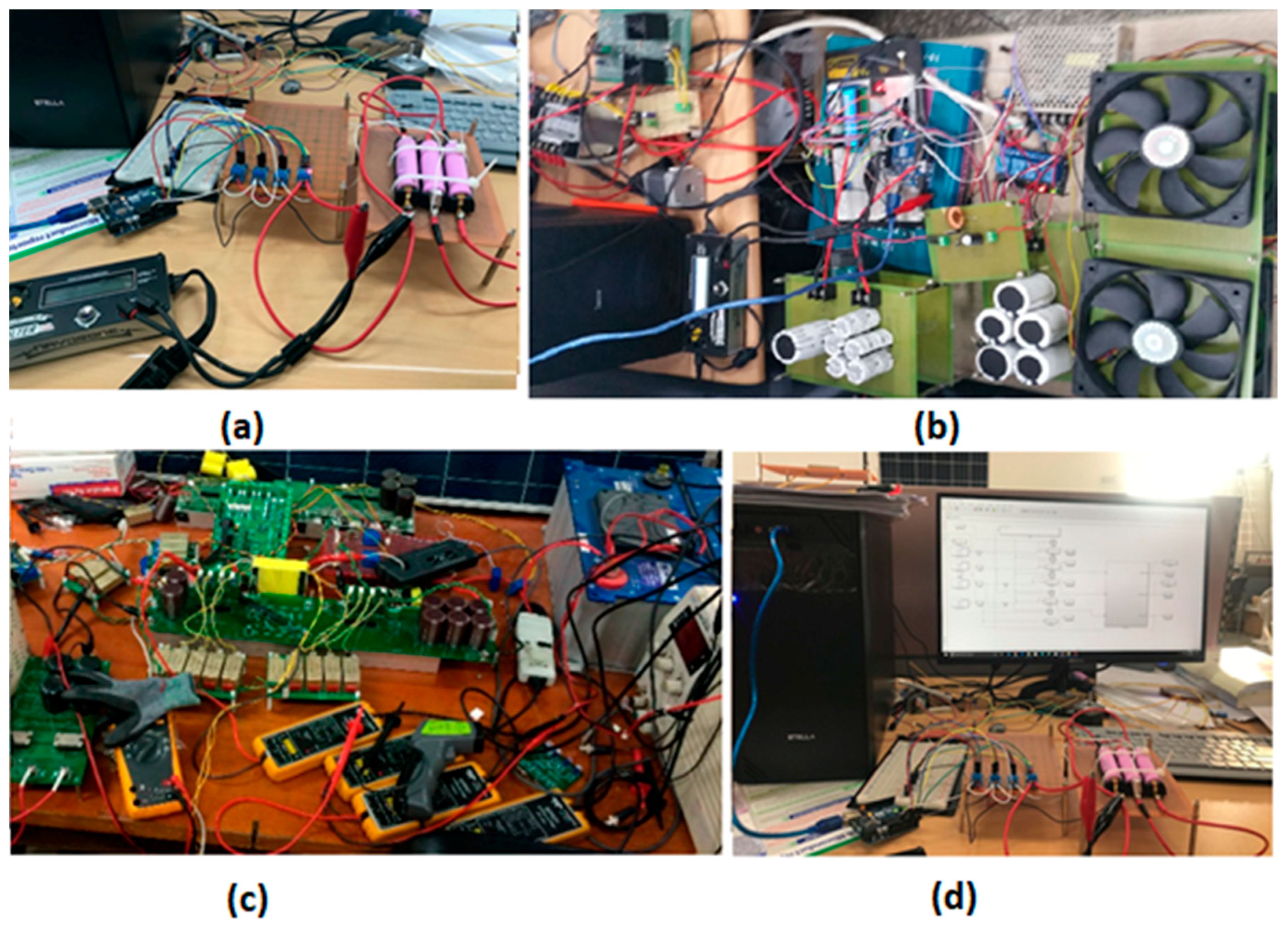
2.2. Materials and Experimental Arrangements

Figure 6 shows the experimental setup for proposed HES. The experimental setup for the proposed EPW power supply and control consist of three arrangements: (1) the FLC for fast charging of Li-Po batteries (Figure 6a,d), (2) the fuzzy logic intelligent energy management system (Figure 6b); and (3) the DAB converter setup (Figure 6c). In the DAB-IBDC topology, the active bridges for both sides were designed using a 47N60C3 power MOSFET (Texas Instruments, Dallas, TX, USA) with a drain-source resistance of 0.07 Ω. To trigger the MOSFET switches in high frequency (f > 10 kHz) applications, pulse width modulation (PWM) signals (±7 to ±30 V, 3 mA) were applied through the gate-source terminal. The PWM signals were produced using a digital signal processor (TMS320F28335, (Texas Instruments, Dallas, TX, USA) based on the control algorithm. A MOSFET driving circuit was designed and used to interface the DSP and MOSFET switches, as the PWM signals from the TMS320F28335 (Texas Instruments, Dallas, TX, USA) do not have sufficient power to operate the switches. The rapid charging FLC algorithm was implemented using a Samsung 18750 (Samsung, Seocho, Seoul, Korea) stacked in series with a Hall-effect-based current sensing ACS712 IC (eleparts, Dangsan-Dong, Seoul, Korea) to monitor the motor current. A voltage sensor was used to monitor the SC bank voltage with a three-channel relay for switching. To achieve these goals, two different experimental setups were introduced. (1) To achieve safe charging, and the rapid-charging characteristics of the SC bank and drive, a distinct comparison between the different charging current was made. For this, five supercapacitors (100 F each) in series, and a 12 V charging source as a supply with a series resistor for current controlling were used. In this experiment, the specifications of a SC shown in Table 1were used to record the thermal image during the charging process, a VT04A visual IR thermometer (FLUKE, Everett, WA, USA) with different charging currents was used. The specification of the SC used for experimental setup is given in Table 1.

3. Results and Discussion

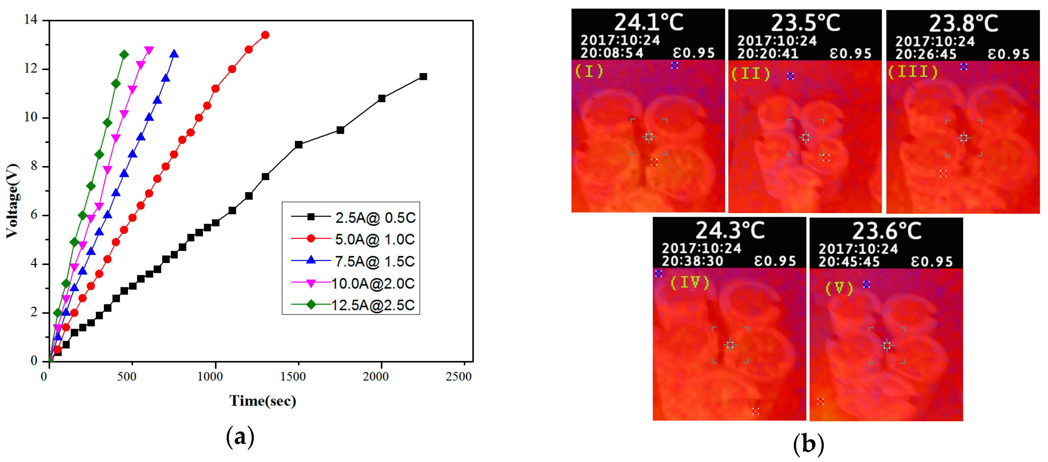
3.1. Investigating the Fast Charging Characteristics of SC Bank

Li-Po/Li-ion batteries, as power sources in rapid charging, are a hot research topic because UAVs require several hours to completely recharge once discharged. Rapid charging of these batteries is not possible by only increasing the charging current because charging a chemical process affects the charge transfer capabilities, e.g., the formation of resistive films on the active particle surface, reduction/oxidation of materials other than the active material, and finite diffusion rate of lithium ions in electrolytes. Only a finite amount of current is allowed to pass through the batteries because of these limitations. The battery health is affected directly by faster charge transfer. Therefore, the manufacturers recommend keeping the charging current between 0.5 C and 1.0 C because of the limits of the operating temperature domain, maximum charge/discharge current, and limits of lower and upper cut-off. This study examined the charging time in this/the proposed HEPS, in which the SC bank was used as a fast charging source, five supercapacitors (100 F each) connected in series, and characteristics for charging at five different charging rates (2.5 A, 5 A, 7.5 A, 10 A, and 12.5 A) same as 0.5 C, 1.0 C, 1.5 C, 2.0 C, and 2.5 C, respectively, of a Li-Po battery (5000 mAh, 11.1 V). Thermal images were taken for every charging current to check the effect of the charging current on the SC bank temperature. To fully charge SC banks at a charge charging current of 2.5, 2.5 A, 5 A, 7.5 A, 10 A, and 12.5 A, it took the 2250 s, 1300 s, 800 s, 600 s, and 450 s, respectively. Figure 7a presents the charging time curve.
Figure 7b displays thermal images of SC bank for charging currents shown in Figure 7a (i.e., 2.5 A, 5.0 A, 7.5 A, 10.0 A, and 12.5 A). Figure 7b shows that it is safe to use to use such a high current to charge a SC bank because there was no significant increase in temperature during these charging currents. As the charging current was increased, the charging time of the SC decreased without a rise in temperature.

3.2. Performance Evaluation of the FLC Charger

Rapid charging of the proposed FLC charging system was confirmed using the flowchart explained in Section 2.1.2.3 and recording the data from the experimental setup developed in Section 3. The fuzzy controlled bypass equalization helped reduce the charging time of the Li-ion batteries. Figure 8 compares the conventional CC-CV charging with the FLC for a three-cell arrangement. Figure 8a shows the output current based on the cell voltage and voltage difference for the defined FIS (fuzzy interface system) variables (cell voltage and output current) with membership functions (very small, small, medium, large, very large). An increase in the charging current decreases the charging time, and Figure 8b shows the charging characteristics of Li-ion batteries at 0.5 C, 1 C, 1.5 C, and 2.0 C for CC-CV and FLC chargers. Figure 8b shows the voltage of the batteries and time required to fully charge the cell at different charging currents. During the process of Li-ion charging, a fuzzy control device was used for feedback control, which is used in the FLC charger and fine-tuning, resulting in an increased output current to shorten the charging time. The performance of the FLC-based charger increased with increasing charging current, as shown in Figure 8c. The FLC controlled BPE proposed in Section 2.1.2.3 is the main reason for the reduced charging time. A net percentage decrease of 13.13%, 12.26%, 13.60%, and 19.23% occurred at 1 C, 1.5 C, and 2.0 C, respectively, with FLC charging compared to CC-VV charging (as highlighted in Figure 8c).

3.3. Power Conversion System

An experimental module of the DAB converter was designed and analyzed at a 2.8 kW load for the proposed HESS was analyzed as shown in Figure 9. The input source on the primary side of the DAB converter is connected to the DC-bus HESS to the energy storage component (i.e., SC and Li-ion, which operate in parallel). A phase shift was introduced and the Vcd square wave was shifted from the Vab square wave, as shown in Figure 9. The switching frequency was kept high and a fixed value, i.e., fs = 70 kHz, was used. The orange line waveforms represent Vab, while dark pink, blue, and green represent Vcd, battery current, and battery voltage. The experimental module for the DAB converter captures the operating point maximum power at a phase shift d = 0.3 and a battery voltage of 28 V. The high-value switching frequency offers low phase shift values required at full load. The secondary side switches reduce the conduction losses. The DAB converter can operate both in buck and boost modes. Results for buck mode when ESS charging is in progress is shown in Figure 9a and when the ESS is fully charged is shown in Figure 9b. The experimental results show the current at 100 A when the battery voltage is limited to 2.8 kW.

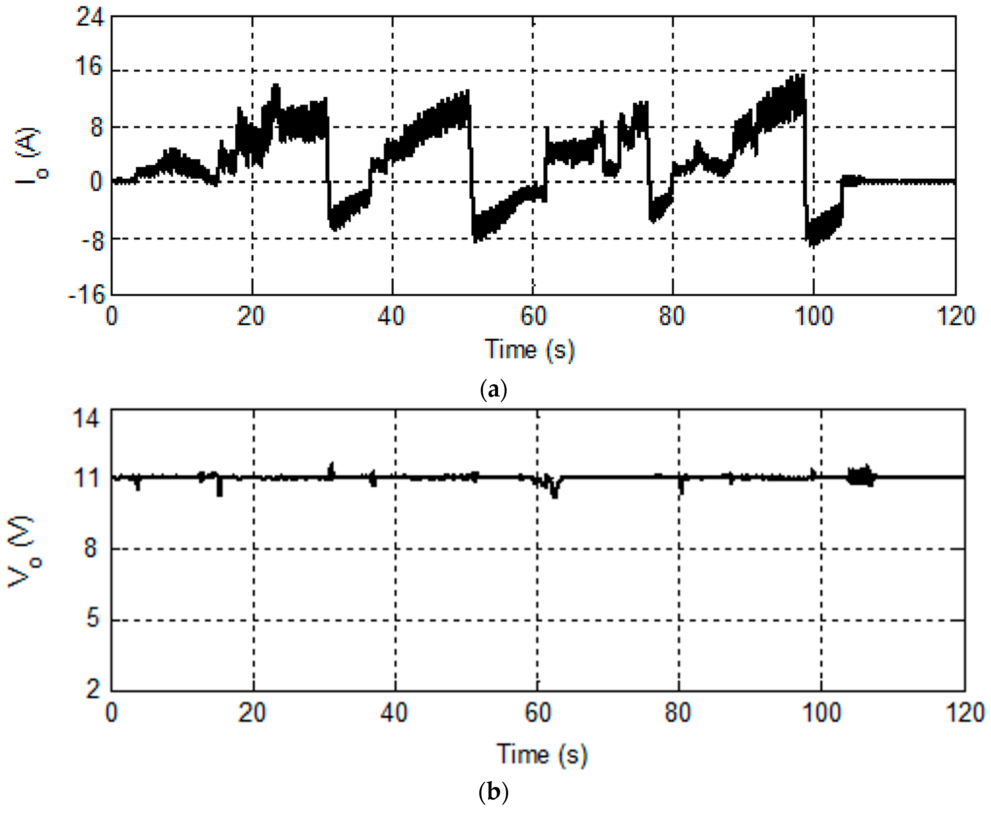
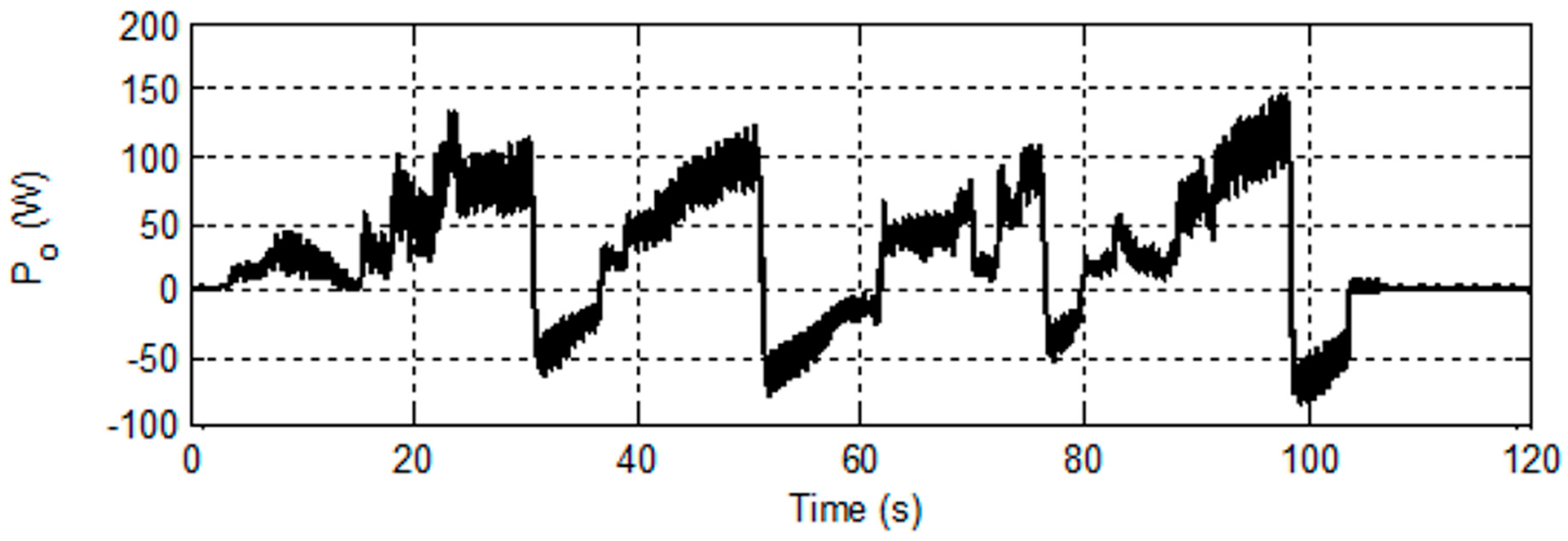
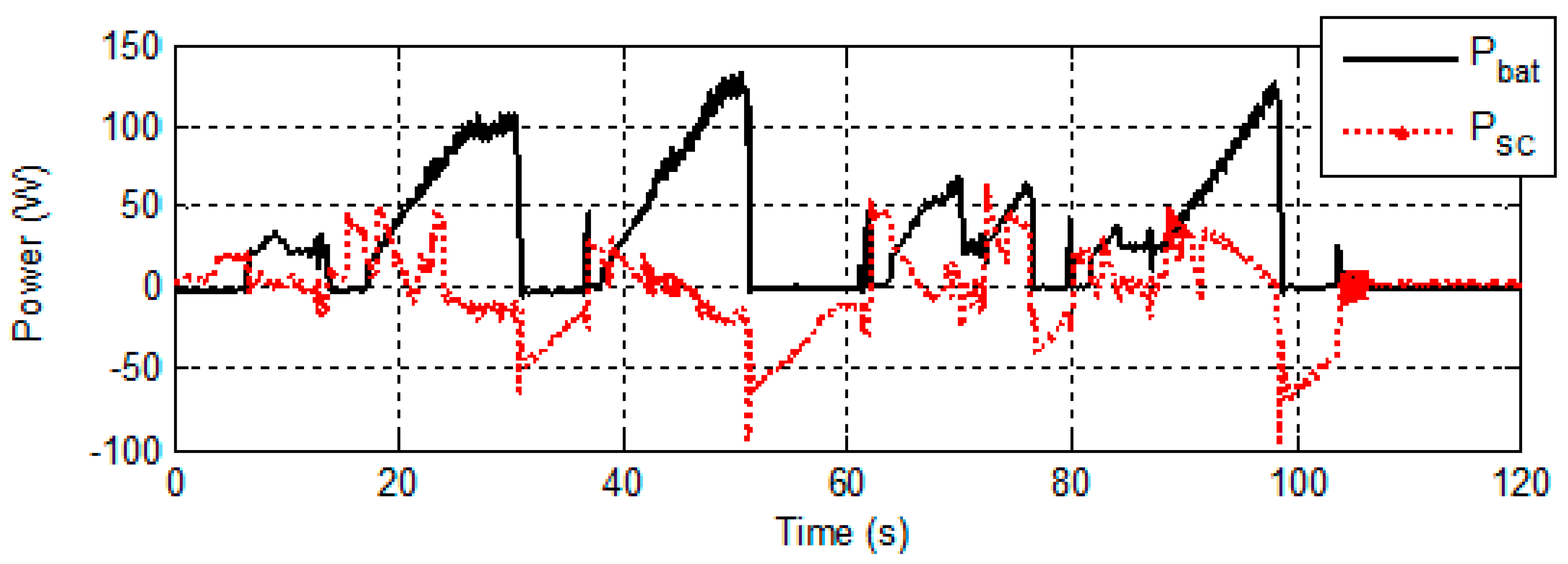
3.4. Performance Evaluation of FLIEMS

To confirm the effective use of the FLIEMS, the profile for the wheelchair speed and distance covered was designated. Figure 10 presents the distance variation and speed. The speed profile of the wheelchair increased and decreased, highlighting different needs of power during the movement of EPW at such speeds. The maximum speed acquired by EPW in Figure 10 is about 5.2 km/h while the net distance covered by the EPW is approximately 250 m.
Figure 11 depicts the variations in the output voltage and current changes according to the wind and speed profile highlighted in Figure 10 using the FLIEMS. The current demand for the motor in an electric wheelchair alters the output current fluctuation with acceleration and deceleration during the different time intervals (see Figure 11a). The output voltage remains constant with almost no variation in the output voltage waveform providing proof that the voltage is regulated regardless of the variations in the output current (Figure 11b). On the other hand, the FLIEMS showed that the output voltage regulation was successful. This shows that the proposed FLIEMS can properly realize the transition occurring during the different operation modes.
Figure 12 shows the change in the resulting output power level and the source power level. The maximum output power during the movement of an electric wheelchair and regenerative braking were approximately 150 W and 90 W, respectively.
FMIEMS smartly controls the power flow from both the sources, i.e., lithium ion and SC at the very beginning, and the SC is discharged instantly to fulfill the power requirement of the motor. Owing to the increase in the power demand of the motor, the battery power becomes dominant over the SC power. In addition, priority is given to the SC to recharge itself by the energy produced during regenerative braking due to the inherent rapid charging characteristics of the SC.
Li-ion battery power is controlled and smoothed using the FLIEMS. On the other hand, the net amount of power delivered by the Li-ion batteries is controlled by the rate limiter defined in the energy management strategy and it is quite clear from the Figure 13 that SC attempts to contribute to Li-ion batteries in parallel to fulfill the power demand of the load. The rate limiter used in the controller strategy improves the battery power considerably by limiting the power extracted from the Li-ion batteries.

4. Conclusions

This paper discussed a novel hybrid power supply for an EPW. The FLIEMS was designed for the effective utilization of SCs, i.e., to smoothly regulate the battery power profile and use it when rapid charge or discharge is needed. By applying this FLIEMS, it was targeted to ensure the operability of the hybrid system and decrease the battery power peaks to extend the battery life. In this paper, a Li-ion charging system was charged using FCFLC. The FLC control charging method shortens the charging time. FLC-based bypass equalization (BPE) cell voltage balancing has been used to reduce the voltage differences, avoid overcharging, and improve the battery charging efficiency. The charging time was reduced by 13.13%, 12.26%, 13.60%, and 19.23% for 1C, 1.5 C, and 2.0 C, respectively, using the FLC charger discussed in this paper compared with conventional CC-CV charging. The proposed method will make battery operation safer and develop a complete set of battery charge-discharge management systems. DAB-IBDC converter was used for the effective charging and discharging of SC banks in the various modes of operation.

Author Contributions

Hee-Je Kim, Hwan-Gue Cho, and Muhammad Adil Khan conceptualized the idea of this research work. Hee-Je Kim and Hwan-Gue Cho developed the proposal to the funding body. Muhammad Adil Khan designed the experimental setup and procured the equipment and the material required for the experimental work. The fabrication and integration of the experimental setup was mostly carried out by the Muhammad Adil Khan under the supervision of Hee-Je Kim. P. Sathishkumar, Muhammad Umair Ali, S. Hussain, and M. Ishfaq helped with the experimental work and fabrication of the power conversion circuit. Results were analyzed by Kamran Zeb, Waqar Uddin, and Imran Khan. The paper was written by all the authors with different degrees of contribution.

Acknowledgments

This research was supported by Basic Research Laboratory through the National Research Foundations of Korea funded by the Ministry of Science, ICT, and Future Planning (NRF-2015R1A4A1041584).

Conflicts of Interest

The authors declare no conflict of interest.

References

  1. Kurzweil, P.; Brandt, K. Secondary batteries–lithium rechargeable systems overview. In Encyclopedia of Electrochemical Power Sources; Garche, J., Chris, D., Moseley, P., Ogumi, Z., Rand, D., Scrosati, B., Eds.; Elsevier: Amsterdam, The Netherlands, 2009; Volume 5, pp. 169–176. [Google Scholar]
  2. Rivera-Barrera, J.P.; Muñoz-Galeano, N.; Sarmiento-Maldonado, H.O. SoC Estimation for Lithium-ion Batteries: Review and Future Challenges. Electronics 2017, 6, 102. [Google Scholar] [CrossRef]
  3. Mubenga, N.S.; Linkous, Z.; Stuart, T. A Bilevel Equalizer for Large Lithium Ion Batteries. Batteries 2017, 3, 39. [Google Scholar] [CrossRef]
  4. Pozo, B.; Garate, J.I.; Ferreiro, S.; Fernandez, I.; Fernandez de Gorostiza, E. Supercapacitor Electro-Mathematical and Machine Learning Modelling for Low Power Applications. Electronics 2018, 7, 44. [Google Scholar] [CrossRef]
  5. Frenzel, B.; Kurzweil, P.; Rönnebeck, H. Electromobility concept for racing cars based on lithium-ion batteries and supercapacitors. J. Power Sources 2011, 196, 5364–5376. [Google Scholar] [CrossRef]
  6. Shah, N.; Czarkowski, D. Supercapacitors in Tandem with Batteries to Prolong the Range of UGV Systems. Electronics 2018, 7, 6. [Google Scholar] [CrossRef]
  7. Lee, J.; Yi, J.; Kim, D.; Shin, C.B.; Min, K.-S.; Choi, J.; Lee, H.-Y. Modeling of the Electrical and Thermal Behaviors of an Ultracapacitor. Energies 2014, 7, 8264–8278. [Google Scholar] [CrossRef]
  8. Pay, S.; Baghzouz, Y. Effectiveness of battery–supercapacitor combination in electric vehicles. In Proceedings of the 2003 IEEE Bologna Power Tech Conference, Bologna, Italy, 23–26 June 2003. [Google Scholar]
  9. Faggioli, E.; Rena, P.; Danel, V.; Andrieu, X.; Mallant, R.; Kahlen, H. Supercapacitors for the energy management of electric vehicles. J. Power Sources 1999, 84, 261–269. [Google Scholar] [CrossRef]
  10. Khan, M.A.; Badshah, S. Design and analysis of cross flow turbine for micro hydro power application using sewerage water. RJASET 2014, 8, 821–828. [Google Scholar] [CrossRef]
  11. Brown, J.C.; Eichenberg, D.J.; Thompson, W.K.; Viterna, L.A.; Soltis, R.F. Ultracapacitors Store Energy in Hybrid Electric Vehicles; NASA Tech Briefs; NASA Glenn Research Center, Commercial Technology Office: Cleveland, OH, USA, 2000; pp. 63–64.
  12. Khan, M.A.; Zeb, K.; Sathishkumar, P.; Rao, S.S.; Gopi, C.V.; Kim, H.-J. A Novel Off-Grid Optimal Hybrid Energy System for Rural Electrification of Tanzania Using a Closed Loop Cooled Solar System. Energies 2018, 11, 905. [Google Scholar] [CrossRef]
  13. Khan, M.A.; Ko, B.; Alois Nyari, E.; Park, S.E.; Kim, H.-J. Performance Evaluation of Photovoltaic Solar System with Different Cooling Methods and a Bi-Reflector PV System (BRPVS): An Experimental Study and Comparative Analysis. Energies 2017, 10, 826. [Google Scholar] [CrossRef]
  14. Xiao, R.; Liu, B.; Shen, J.; Guo, N.; Yan, W.; Chen, Z. Comparisons of Energy Management Methods for a Parallel Plug-In Hybrid Electric Vehicle between the Convex Optimization and Dynamic Programming. Appl. Sci. 2018, 8, 218. [Google Scholar] [CrossRef]
  15. Dimitrov, B.; Krishna, M.; Cruden, A.; Sharkh, S.; Elkhateb, A. Analysis, Design, and Experimental Validation of a Primary Side Current-Sensing Flyback Converter for Use in a Battery Management System. Electronics 2018, 7, 43. [Google Scholar] [CrossRef]
  16. Pan, L.; Zhang, C. An Integrated Multifunctional Bidirectional AC/DC and DC/DC Converter for Electric Vehicles Applications. Energies 2016, 9, 493. [Google Scholar] [CrossRef]
  17. Shin, D.; Kim, Y.; Wang, Y.; Chang, N.; Pedram, M. Constant-current regulator-based battery-supercapacitor hybrid architecture for high-rate pulsed load applications. J. Power Sources 2012, 205, 516–524. [Google Scholar] [CrossRef]
  18. Moonem, M.A.; Pechacek, C.L.; Hernandez, R.; Krishnaswami, H. Analysis of a Multilevel Dual Active Bridge (ML-DAB) DC-DC Converter Using Symmetric Modulation. Electronics 2015, 4, 239–260. [Google Scholar] [CrossRef]
  19. Wang, Y.Z.; Wang, W.D.; Zhao, Y.L.; Yang, L.; Chen, W.J. A Fuzzy-Logic Power Management Strategy Based on Markov Random Prediction for Hybrid Energy Storage System. Energies 2013, 105, 304–318. [Google Scholar] [CrossRef]
  20. Furkan, A.; Yakup, T.; Bulent, V. An Energy Management Strategy for a Concept Battery/Ultracapacitor Electric Vehicle with Improved Battery Life. IEEE Trans. Transp. Electr. 2016, 3, 191–200. [Google Scholar]
  21. Nüesch, T.; Elbert, P.; Flankl, M.; Onder, C.; Guzzella, L. Convex Optimization for the Energy Management of Hybrid Electric Vehicles Considering Engine Start and Gearshift Costs. Energies 2014, 7, 834–856. [Google Scholar] [CrossRef]
  22. Van Reeven, V.; Huisman, R.; Pesgens, M.; Koffrie, R. Energy management control concepts with preview for hybrid commercial vehicles. In Proceedings of the 6th International Conference on Continuously Variable and Hybrid Transmissions, Maastricht, The Netherlands, 17–19 November 2010. [Google Scholar]
  23. Khan, M.A.; Badshah, S. Measures for reducing transmission and distribution losses of Pakistan. Int. J. Sci. Eng. Res. 2014, 4, 616–619. [Google Scholar]
  24. Smith, T.A.; Mars, J.P.; Turner, G.A. Using supercapacitors to improve battery performance. In Proceedings of the IEEE 33rd Annual Power Electronics Specialists Conference, Cairns, Australia, 23–27 June 2002; pp. 124–128. [Google Scholar]
  25. Zhou, F.; Xiao, F.; Chang, C.; Shao, Y.; Song, C. Adaptive Model Predictive Control-Based Energy Management for Semi-Active Hybrid Energy Storage Systems on Electric Vehicles. Energies 2017, 10, 1063. [Google Scholar] [CrossRef]
  26. Arnet, B.J.; Haines, L.P. Hig-power DC-to-DC converter for supercapacitors. In Proceedings of the IEEE International Electric Machines and Drives Conference, Cambridge, MA, USA, 17–20 June 2001; pp. 1160–1165. [Google Scholar]
  27. Bertoni, L.; Gualous, H.; Bouquain, D.; Hissel, D.; Pera, C.; Kauffmann, J.M. Hybrid auxiliary power unit (APU) for automotive applications. In Proceedings of the IEEE 56th Vehicular Technology Conference, Vancouver, Canada, 24–28 September 2002; pp. 1840–1845. [Google Scholar]
  28. Kisacikoglu, M.C.; Uzunoglu, M.; Alam, M.S. Fuzzy logic control of a fuel cell/battery/ultra-capacitor hybrid vehicular power system. In Proceedings of the 2007 IEEE Vehicle Power and Propulsion Conference, Arlington, TX, USA, 9–12 September 2007; pp. 591–596. [Google Scholar]
  29. Ferreira, A.A.; Pomilio, J.A.; Spiazzi, G.; Araujo Silva, L. Energy management fuzzy logic supervisory for electric vehicle power supplies system. IEEE Trans. Power Electron. 2008, 23, 107–115. [Google Scholar] [CrossRef]
  30. Qiao, Z.; Weiwen, D.; Sumin, Z.; Jian, W. A Rule Based Energy Management System of Experimental Battery/Supercapacitor Hybrid Energy Storage System for Electric Vehicles. J. Control Sci. Eng. 2016, 2016. [Google Scholar] [CrossRef]
  31. Khan, M.A.; Krishna, T.N.V.; Sathishkumar, P.; Sarat, G.; Kim, H.-J. A hybrid power supply with fuzzy controlled fast charging strategy for mobile robots. In Proceedings of the International Conference on Information and Communication Technology Robotics (ICT-ROBOT 2016), Busan, Korea, 7–9 September 2016. [Google Scholar]
  32. Pelusi, D. Genetic-neuro-fuzzy controllers for second order control systems. In Proceedings of the IEEE 5th UKSim European Symposium on Computer Modeling and Simulation (EMS), Madrid, Spain, 16–18 November 2011; pp. 12–17. [Google Scholar]
  33. Pelusi, D. PID and intelligent controllers for optimal timing performances of industrial actuators. Int. J. Simul. Syst. Sci. Technol. 2012, 132, 65–71. [Google Scholar]
  34. Lee, Y.S.; Cheng, M.W. Intelligent Control Battery Equalization for Series Connected Lithium-Ion Battery Strings. IEEE Trans. Ind. Electron. 2005, 52, 1297–1307. [Google Scholar] [CrossRef]
  35. Erdinc, O.; Vural, B.; Uzunoglu, M. A wavelet-fuzzy logic based energy management strategy for a fuel cell/battery/ultra-capacitor hybrid vehicular power system. J. Power Sources 2009, 194, 369–380. [Google Scholar] [CrossRef]
  36. Li, Y.; Yang, D.; Ruan, X. A systematic method for generating multiple-input dc/dc converters. In Proceedings of the Vehicle Power and Propulsion Conference, Harbin, China, 3–5 September 2008; pp. 1–6. [Google Scholar]
  37. Zhang, L.; Peng, H.; Ning, Z.; Mu, Z.; Sun, C. Comparative Research on RC Equivalent Circuit Models for Lithium-Ion Batteries of Electric Vehicles. Appl. Sci. 2017, 7, 1002. [Google Scholar] [CrossRef]
  38. Chiang, Y.H.; Sean, W.Y.; Ke, J.C. Online estimation of internal resistance and open-circuit voltage of lithium-ion batteries in electric vehicles. J. Power Sources 2011, 196, 3921–3932. [Google Scholar] [CrossRef]
  39. Seaman, A.; Dao, T.S.; Mcphee, J. A survey of mathematics-based equivalent-circuit and electrochemical battery models for hybrid and electric vehicle simulation. J. Power Sources 2014, 256, 410–423. [Google Scholar] [CrossRef]
  40. Grbovic, P.J.; Philippe, D.; Philippe, L.M.; Patrick, B. The Ultracapacitor-Based Controlled Electric Drives with Braking and Ride-Through Capability: Overview and Analysis. IEEE Trans. Ind. Electron. 2011, 3, 925–936. [Google Scholar] [CrossRef]
  41. Grbovic, P.J.; Philippe, D.; Philippe, L.M.; Patrick, B. A Three Terminal Ultracapacitor-Based Energy Storage and PFC Device for Regenerative Controlled Electric Drives. IEEE Trans. Ind. Electron. 2012, 59, 301–316. [Google Scholar] [CrossRef]
  42. Sathishkumar, P.; Piao, S.; Khan, M.A.; Kim, D.H.; Kim, M.S.; Jeong, D.K.; Lee, C.; Kim, H.J. A Blended SPS-ESPS Control DAB-IBDC Converter for a Standalone Solar Power System. Energies 2017, 10, 1431. [Google Scholar] [CrossRef]
  43. Xiong, F.; Wu, J.; Hao, L.; Liu, Z. Backflow Power Optimization Control for Dual Active Bridge DC-DC Converters. Energies 2017, 10, 1403. [Google Scholar] [CrossRef]
  44. Sathishkumar, P.; Krishna, T.N.V.; Khan, M.A.; Zeb, K.; Kim, H.-J. Digital Soft Start Implementation for Minimizing Start up Transients in High Power DAB-IBDC Converter. Energies 2018, 11, 956. [Google Scholar] [CrossRef]
Figure 1. Block diagram and an overview of the proposed HESS for the EPW.
Electronics 07 00063 g001
Figure 2. Li-ion battery equivalent circuit model.
Electronics 07 00063 g002
Figure 3. Algorithm for the bypass equalization (BPE) technique controlled by the FLC controller for multi-cell lithium-ion batteries.
Electronics 07 00063 g003
Figure 4. A detailed overview of the FLIEMS for EPW.
Electronics 07 00063 g004
Figure 5. Complete assembly for the DAB IBDC converter with switches, transformer, drivers, sensor, and DSP controller.
Electronics 07 00063 g005
Figure 6. Experimental setup for (a) the FLC charger (hardware); (b) the FLIEMS; (c) the DAB-IBDC converter; and (d) the FLC charger (software-hardware interfacing).
Electronics 07 00063 g006
Figure 7. (a) Charging characteristics at different charging currents (2.5 A, 5.0 A, 7.5 A, 10.0 A, and 12.5 A); and (b) thermal images of the SC bank at different charging currents (I) 2.5 A, (II) 5.0 A, (III) 7.5 A, (IV) 10.0 A, and (V) 12.5 A.
Electronics 07 00063 g007
Figure 8. (a) Output current based on cell voltage and voltage difference for defined FIS variables (cell voltage and output current) with membership functions (very small, small, medium, large, very large); (b) voltage curves at 0.5 C, 1.0 C, 1.5 C, and 2.0 C for the proposed FLC charger and the CC-CV charging method; and (c) the performance evaluation and comparison between the proposed FLC charger and the conventional CC-CV charging.
Electronics 07 00063 g008aElectronics 07 00063 g008b
Figure 9. Experimental results of DAB-IBDC converter (a) when charging process is continued (ON) and (b) when the batteries are fully charged.
Electronics 07 00063 g009
Figure 10. Variable speed and distance profile for the EPW.
Electronics 07 00063 g010
Figure 11. Output (a) current; and (b) voltage for the EPW.
Electronics 07 00063 g011
Figure 12. Output power for the EPW with FLIEMS.
Electronics 07 00063 g012
Figure 13. Li-ion batteries and SC power profile for EPW due to FLIEMS.
Electronics 07 00063 g013
Table 1. Specification of the supercapacitor used for experimental analysis.
Rated Voltage (VR) at 65 °C 2.7 VDC
Surge Voltage2.85 VDC
Rated Capacitance100 F
DC-ESRMax. 12 mΩ Avg. 8 mΩ
Leakage CurrentMax. 0.26 mA
Max. Continuous Current17 A (ΔT = 40 °C)
Max. Peak Current61 A (at 65 °C)
Max. Stored Energy0.10 Wh (at 65 °C)
Specific Power7230 W/kg
Endurance1500 h (at 65 °C, 2.7 V)

