A Survey on Formal Verification Techniques for Safety-Critical Systems-on-Chip


1
Chair of Embedded Systems for Information Technology, Ruhr-University Bochum, Universitätsstraße 150, 44801 Bochum, Germany
2
Communications and Embedded Systems Laboratory, Federal University of Santa Catarina, Campus Reitor João David Ferreira Lima, s/n, 88040-900 Florianópolis, Brazil
*
Author to whom correspondence should be addressed.
Electronics 2018, 7(6), 81; https://doi.org/10.3390/electronics7060081
Submission received: 23 April 2018
/
Revised: 17 May 2018
/
Accepted: 24 May 2018
/
Published: 26 May 2018
(This article belongs to the Special Issue Hardware and Architecture)
Abstract
:The high degree of miniaturization in the electronics industry has been, for several years, a driver to push embedded systems to different fields and applications. One example is safety-critical systems, where the compactness in the form factor helps to reduce the costs and allows for the implementation of new techniques. The automotive industry is a great example of a safety-critical area with a great rise in the adoption of microelectronics. With it came the creation of the ISO 26262 standard with the goal of guaranteeing a high level of dependability in the designs. Other areas in the safety-critical applications domain have similar standards. However, these standards are mostly guidelines to make sure that designs reach the desired dependability level without explicit instructions. In the end, the success of the design to fulfill the standard is the result of a thorough verification process. Naturally, the goal of any verification team dealing with such important designs is complete coverage as well as standards conformity, but as these are complex hardware, complete functional verification is a difficult task. From the several techniques that exist to verify hardware, where each has its pros and cons, we studied six well-established in academia and in industry. We can divide them into two categories: simulation, which needs extremely large amounts of time, and formal verification, which needs unrealistic amounts of resources. Therefore, we conclude that a hybrid approach offers the best balance between simulation (time) and formal verification (resources).
1. Introduction
The high degree of miniaturization in the electronics industry has been for several years a driver to push embedded systems to different fields and applications. Several application domains benefit from this miniaturization process. Two very prominent areas are consumer electronics, where we have the Internet-of-Things (IoT) [1] as the biggest player, and Industry 4.0, with the increase in automation in industrial processes [2,3].
Other fields that saw an increase in the adoption of embedded systems are the many different safety-critical applications that serve us daily either directly or indirectly. The most notable examples are automotive, aerospace, and medical. As a side note, the automotive industry has seen a great increase in the use of systems-on-chip in recent years. Today’s luxury cars may have up to 100 Electronic Control Units (ECUs) collecting sensor data and controlling many different functions [4]. The advantages of embedded systems for these areas include reduced form factor, lower costs, and specialized functionalities. Along with these advantages, functional safety standards are in use to help guarantee a minimum level of dependability, since, in these fields, human lives are at stake.
Nevertheless, these standards, e.g., ISO 26262 for automotive applications and DO-254 for the aerospace industry, are mostly like general guidelines, to steward the design process in order to achieve the desired dependability level. The “real” procedures that will make sure that this result is achieved usually takes shape in a thorough verification process [5].
During the design of hardware systems, verification teams use several techniques to verify the functionality to assure that no errors exist when the product is ready. However, in the development flow of critical systems, further measures must be taken into account, as these systems are constantly dealing with human lives. Therefore, techniques that can somehow prove that a design conforms to its specification or to a standard are great additions to the verification flow. Such tools employ formal techniques based on mathematical methodologies, and with them, it is possible to guarantee that portions of an architecture are correct.
Formal Verification (FV) provides methods and techniques to mathematically prove the correctness of a system, such as Theorem Proving [6,7] and Model Checking [8,9] and can be adopted early in the development process.
Theorem Proving relies heavily on high order logic and uses mathematical structures to build formulas that correspond to the behavior of the system. The verification process, then, is the evaluation of these formulas. Projects of any complexity can apply this method since it does not deal with states, but with formulas. However, it demands a high degree of knowledge of the design under verification (DUV) and of logic for the user to perform the verification. Moreover, since this process involves complex formulas, it is difficult to automate. The user must perform the proving systematically, creating the formulas, feeding them to the tool and analyzing the results [10,11].
Model checking verifies properties against a model to prove that the design conforms to the specifications. The main advantage of this technique is that it reports illegal paths, known as counterexamples, which supports the correction of bugs. One problem inherent to this technique, however, is state space explosion, since the number of states used to model the system grows exponentially with the number of variables [12,13]. To counter this problem, new techniques to reduce the state space footprint exist, thus allowing verification of larger projects.
Other techniques used in the verification flow of hardware systems are Equivalence Checking, Simulation, and Semiformal Verification. However, these techniques need a more mature version of the architecture to begin the verification process.
Equivalence Checking compares different levels of the same implementation to guarantee that they are functionally the same. This is a step commonly performed after the netlist is generated, where the generated description is compared to the register transfer level (RTL) that describes it. Furthermore, this technique checks the consistency of an optimization after its implementation or between different abstraction levels. In such case, a tool compares a higher-level functional description of the system to the generated or implemented low-level RTL code [14]. Some caution is necessary in this case, as the correlation between these implementations is not direct.
Simulation is a method widely used in industry, due to its easy adoption and it gives a very good idea of the system’s behavior. However, because it depends on input vectors to stimulate the circuit, when the number of input signals increases, more test vectors are needed to ensure that the system is completely correct and complying with the specifications. Thus, simulation cannot cover exhaustively the state space of large systems.
In addition to formal verification techniques, which suffer from scalability problems, there are also hybrid approaches that combine the superior coverage of formal verification and the scalability of simulation.
This survey aims to provide a more detailed overview of the most widely used formal verification techniques and discusses their value for critical SoCs’ verification.
This paper is organized as follows: Section 2 presents a short overview of safety-critical systems and standards. Section 3, Section 4, Section 5, Section 6, Section 7, Section 8 and Section 9 present an overview of the researched techniques. Section 10 discusses each technique regarding critical systems verification and the outline of the next steps in the research. Finally, Section 11 concludes this work.
2. Safety-critical Systems and Functional Safety Standards
According to [15], safety-critical systems deal with three risk events:
- Loss of some kind is associated with it, e.g., human lives, environmental,
- There is an element of chance or uncertainty,
- There is a degree of choice involved.
In light of these points, to ensure safety is to lower the risk of injury or death and the uncertainty to which the system is exposed to and remove as much as possible the choices available to the system. However simplistic this may seem, safety must be built into the system. In other words, system development must target safety. To this effect, a system has to be dependable, and dependability means that the object can be relied on to deliver its service.
Building safety measures into a system happens only through careful planning and analysis, using well-defined implementation methods and enforcing strict and thorough verification techniques. In addition, to aid in all these phases, industrial players develop safety standards to ensure that safety-critical embedded systems follow the correct steps and are adequate for their purposes.
The basic functional safety standard used in the industry is the IEC 61508 standard [16], which is titled “Functional Safety of Electrical/Electronic/Programmable Electronic Safety-related Systems”, but different industry segments have their own standards to work with, which best covers that industry’s needs. For instance, the medical industry has the IEC 60601 standard [17] for electrical equipment, which covers electromagnetic disturbances, radiation protection for X-ray equipment, electrocardiographs, among many others. The avionics industry has the DO-254 and the DO-178 [18] for hardware and software development. The automotive industry has the ISO 26262 standard [19] for functional safety of electrical and/or electronic systems.
All these standards cover the complete lifetime of its subject, from specification to end-of-life treatment, e.g., correct disposal. However, in this study, we focus on the design and verification phase, which encompasses the implementation of the safety-critical system and its technical acceptance in accordance with the standards.
3. Automated Theorem Proving
Automated Theorem Proving (ATP) is the process of determining if some statement (the theorem) is valid or not regarding the axioms for a certain theory using tools to help speed up the proving process [20]. The degree of automation can be greater or smaller, depending on the formalism used to describe the theorems and to model the system.
There are different formalisms, or formal logics used to describe the theorems. Table 1 summarizes the main characteristics of the most common ones.
In increasing order of expressiveness, some typical ones are propositional logic, temporal logic, first-order logic, and higher-order logic [21]. The spectrum covered by these examples of formalisms range from atomic propositions tied together using propositional connectives (propositional logic) to quantification of predicates and functions with predicates and functions for arguments (higher-order logic). However, this increase in expressiveness has the inverse effect on automation. The more expressive a logic is, the less automated it can be. This means that tools for higher-order logic usually work iteratively, where the user is responsible for providing simpler proofs to help guide the verification process.
Another characteristic from these formalisms is the decidability, which is also connected to the expressiveness degree. A theory is decidable if a procedure can determine if it is valid or not. Furthermore, a theory is semidecidable if, when trying to determine its validity, a procedure never returns an answer, although it can determine if a theory is valid.
3.1. Technique Outline
The basic functionality from ATP has two steps: the description of the system and the theorems and the proof. Figure 1 illustrates the system structure for ATP tools.
The first step is accomplished using the adequate formalism, which is a formal language in itself. Each formalism has its intrinsic axioms as the starting point for the prover. Nevertheless, custom axioms can help the prover advance more rapidly with the resolution process in the next step.
The second step is performed either by the prover alone or iteratively with user guidance, depending on the level of automation offered by the formalism. In either case, the prover has several techniques at its disposal to process the theorems and the system description. Some examples, among many others, are
- Rewriting—substitute terms to simplify computations
- Skolemization—elimination of existential quantifiers (∃), leaving only universal ones (∀)
- Tableaux—break down a theorem into its constituent parts and prove or refute them separately.
3.2. Examples of ATP-Based Tools
Three tools based on ATP are PVS, B Method, and Isabelle. Wiedijk [22] summarizes more examples of ATP-based tools.
3.2.1. Prototype Verification System (PVS)
PVS is an interactive prover for higher-order logic and provides two languages to the user: one to write the definitions and the theorems and one to prove the theorems [23].
For the description of the system and the theorems, according to [23], PVS offers base types such as Booleans, integers, and reals as well as user uninterpreted types. Type constructors include functions, sets, tuples, records, enumerations, and inductively-defined abstract data types. The specifications are organized in parameterized theories, which can include assumptions, definitions, axioms, and theorems. The parameters can themselves include constants, types, and theory instances. Finally, it provides the usual arithmetic and logical operators, function application, lambda abstraction, and quantifiers for expressions.
At the theorem prover side, PVS provides primitive inference procedures that include propositional and quantifier rules, induction, rewriting, simplification using decision procedures for equality and linear arithmetic, data and predicate abstraction, and symbolic model checking. These inference procedures are used iteratively under the guidance of the user.
3.2.2. B Method
According to the process implemented in [24], all proof obligations generated by the Atelier B system are translated into the Why3’s (http://why3.lri.fr/) input language by the translation tool. The Why3 toolchain acts as a front-end for SMT provers. The back-end provers used in [24] are Alt-Ergo, CVC3, and Z3.
The proof obligations, then, are fed four-by-four in parallel to the three provers with a 2s time limit. In the end, the unproven commands are fed again into the three provers with a 60s time limit.
The first efforts to try to fully automate the process for all proof obligations from B-theory were presented in [25], where the provers Coq and PVS were used. However, B’s set theory is not formalized; instead, Coq and PVS’ native logic are used.
The next step was presented in [26], which incorporates the proof obligations into Coq’s prover. This way, the proofs are either manual or with Coq’s automatic algorithms.
Still using Coq, however not for proving directly the proof obligations, Jacquel [27] uses it to prove the correctness of the B prover’s rewrite rules.
3.2.3. Isabelle/HOL
Isabelle/HOL is a generic iterative proof assistant capable of dealing with higher-order logic [29].
According to [29], Isabelle/HOL offers specification tools for (co) datatypes, (co) inductive definitions and recursive functions with complex pattern matching.
Isabelle/HOL conducts its proofs through the Isar language, which is capable of generating human-readable output. It also has tools to speed up the proving process by, e.g., performing long chains of reasoning steps to prove formulas, automatically proving linear arithmetic artifacts, and invoking external first-order provers.
On the theory side, Isabelle/HOL comes pre-packaged with a large theory library of formally verified mathematics, including elementary number theory, analysis, algebra, and set theory. It also has many examples from research in formal verification, encompassing applications from both mathematics and computer science.
4. Symbolic Model Checking
Model checking using state exploration is a powerful formal verification tool and widely used in hardware verification. However, its method of explicit state enumeration is highly resource-consuming. Therefore, for systems with thousands of states, it can either limit the number of possible states that the model checker can work on or can prohibit its creation. The exponential growth in the state space has a side effect known as the state space explosion, directly connected to the number of system variables and inputs and output signals [30].
Instead of explicitly enumerating all states, Symbolic Model Checking (SMC) works with sets of symbols. It uses Boolean decision diagrams (BDDs) to represent sets of states and to work with them in bulk operations. This way, it is possible to verify systems that are more complex.
BDDs represent Boolean functions in a canonical form, where a path can be traced from the root node to any of the leaf nodes so that it can easily determine if a path satisfies the Boolean function or not. However, BDDs are highly dependent on the variable ordering, which directly affects their size. Therefore, it is necessary to apply good strategies and heuristics to optimize them correctly. Reduced Ordered BDDs (ROBDDs) are a step further, with the removal of all redundant paths, sharing all possible nodes, and using variable ordering heuristics so that it has a minimum size.
The result of a symbolic model checker when it fails to verify the input is a counterexample, which traces a path from the initial state to the offender state, or the state that caused the proposition to fail. With this trace, a developer can recreate the failure and find out what caused it. An important characteristic of the counterexample is its minimal length, in contrast to simulation traces. While a simulation run may need hundreds to thousands of cycles to reach a failing state, a formal engine may reach this same state with only tens of cycles.
4.1. Technique Outline
SMC uses temporal logic to describe the propositions to verify the system’s behavior, together with the model that describes the system itself. Temporal logic, like Linear Time Logic (LTL) and Computer Tree Logic (CTL), provides the means to create propositions that unite temporal notions with the properties for verification.
The model of a system is composed of the set S of its states, the transition relation R and the valuation L. To certify the correctness of this model, propositions using temporal logic operators verify the paths composed of some or all of the system’s states. Appendix A describes briefly the operators.
Once the formulas are built, the generated BDDs are traversed to reach one of the two possible leaf nodes: “true”, meaning that the property holds, or “false”, meaning that the property does not hold. When a property is false, a counterexample is generated, and the verification engineer can either fix the system architecture or refine the propositions, in the case of a false positive result.
The propositions are fed into the tool, which means that the process is automated.
4.2. Examples of SMC-Based Tools
Three examples of tools based on Symbolic Model Checking are NuSMV2, nuXmv, and Uppaal.
4.2.1. NuSMV2
NuSMV2 targets finite state systems, which, according to [31], encompass hardware systems, software systems, and communication protocols. The input descriptions are done in SMV’s language, the tool that preceded and served as the base for NuSMV2. It is possible to use modules and processes to describe finite state machines while incorporating requirements in LTL and CTL.
NuSMV2’s flow has several steps for transformations and optimizations. The first three steps, flattening, Boolean encoding, and cone of influence, refine the model M and the properties into modules and processes. The result is a synchronous flat model where only the areas inside the cone of influence for each property is considered. This helps to reduce the system complexity and manage the state space size. The resulting model is applied either to BDD- or to SAT-based model checking. For BDD-based verification, the tool builds a BDD representation of the system (step BDD-based Model Construction) and then verifies it (step BDD-based verification). For SAT-based verification, NuSMV2 builds a representation of the model to apply it to the model checker (step Bounded Model Checking). If a counterexample is found, NuSMV2 transforms it to conjunctive normal form (CNF) and feeds it to an SAT solver.
NuSMV2 can be used from front-end to back-end to prove the input properties. It is also possible to redirect the output from some blocks to work with external tools, e.g., Boolean encoding and bounded model checking. NuSMV2 also provides the capability to exchange the provers. Figure 2 presents the steps performed by NuSMV2.
Its inputs are the description of the model under verification and the properties that will be checked against this model. Through the SMC flow, various forms of verification can be used, such as reachability analysis, fair CTL model checking, LTL model checking via reduction to CTL model checking and computation of quantitative characteristics of the model.
NuSMV2 has also a Bounded Model Checking branch (see Section 5).
4.2.2. nuXmv
nuXmv is an evolution of NuSMV. According to [32], it is capable of dealing with finite- and infinite-state systems (typical for software modules), due to its implemented techniques and has been used as the back-end application for many different tools, both academic and industrial.
For finite-state systems, nuXmv extends the functionalities from NuSMV, e.g., complementing the NuSMV language with the And-Inverter Graph (AIGER) format, which is a language used in the AIGER hardware model checking competition.
There is also a vast selection of algorithms for invariant checking, with an improvement on BDD-based invariant checking algorithms, where the user can specify hints for guided reachability.
As for infinite-state systems, nuXmv implements SMT-based algorithms. This aspect is discussed in Section 6.
4.2.3. Uppaal
Uppaal aims at real-time systems, which can be expressed using the theory of timed automata.
Like NuSMV2, Uppaal has its own specification language. However, it uses a modeling language for the specification of the models and a query language for the properties. The modeling language was designed to facilitate the description of finite state machines, where states, clocks and the interactions between them can be expressed. The query language uses a subset of CTL for the state and the path formulas, where the state formulas are properties for individual states and path formulas are properties for traces of the model.
As stated in [33], Uppaal consists of three parts: the editor, the simulator, and the verifier. In the editor, as shown in Figure 3, the user describes the model for the network of timed automata that characterizes the system with its relations of synchronization and update between the states. The simulator, as shown in Figure 3, can be used in three different modes: (a) run the system manually and choose the path to follow, (b) let the system run at random or (c) use a saved or imported trace to check the reachability of a given state. In the simulator view, it is possible to step through and follow the execution of the models. The verifier, as shown in Figure , lets the user add and edit the properties, or “queries” in Uppaal’s interface, for verification and check them. Every property is listed in the Overview frame and has an indicator to show its status (gray if not yet verified, green is satisfied, and red if not satisfied). It is possible to add comments for each property and the Status frame shows the results after the model checker is called on a property. From the verifier, it is also possible to open a trace (or counterexample) in the simulator.
5. Bounded Model Checking
Another technique that tries to overcome the problem caused by the state space explosion of SMC is Bounded Model Checking (BMC) [12]. BMC uses propositional decision procedures (SAT) to model the system, which, as BDDs, are also based on Boolean expressions, but do not try to build a canonical data structure. Because of this, SAT can handle propositional satisfiability procedures with thousands of variables.
Using a depth-first approach, BMC tries to find counterexamples within a bounded length k, which, in turn, generates minimal counterexamples. This way, when verifying a system, paths are walked through up to a length k in order to check its correctness, instead of traversing all states up to the same point. This prevents the state space explosion up to length k.
On the other hand, as BMC searches the states up to a given bound (k), bugs in deeper states tend to remain hidden. For this reason, a proof using BMC can be incomplete.
5.1. Technique Outline
SAT procedures involve the construction of Boolean formulas and the process of finding one possible combination of values that satisfy them, or stating that it is impossible to be satisfied.
In BMC, SAT and temporal properties are used to verify the correctness of the model. In this way, propositional formulas are generated if and only if a counterexample exists. That is, if all the to-be-verified properties hold, then a counterexample does not exist.
Through this methodology, the formula is generated, where C is the states that the model is made up from unrolled up to length k and P are the properties used to validate the state’s behavior. Then, the next step in this process is to feed this formula into an SAT solver. If the formula is satisfiable, then the implementation is not correct and a counterexample is generated. However, if the formula is not satisfiable, then a counterexample does not exist, and thus the system is correct. In order to keep the advantage of speed in the BMC approach, k tends to be small. It is possible to work with a threshold value for it, where the code will be unrolled until k and, if no counterexample is returned, k is incremented and the verification process continues.
5.2. Examples of BMC-Based Tools
Three examples of tools based on BMC are CBMC, EBMC, and LLBMC.
5.2.1. CBMC
CBMC aims at model checking of ANSI-C programs. As specified in [34], the tool includes the verification of pointer safety, array bounds, and user-provided assertions. One of this tool’s focus is the verification of functional software prototypes of hardware architecture written in ANSI-C. As this tool supports all ANSI-C features (e.g., basic data types, integer operators, type casts, function calls, control flow statements, non-determinism, arrays, structures, named unions, pointers, and dynamic memory), the developed software does not need to be rewritten to fit the tool. This way, this initial software prototype serves also as a reference model for later comparisons.
CBMC provides a graphical interface to help in the visualization of its various aspects, e.g., stepping through the trace of a counterexample, keep track of the value of variables with the use of Watches. CBMC has also the capability of performing equivalence checking with Verilog implementations using watches for signals’ values with waveforms.
In the latest versions, CBMC provides support for external SMT solvers.
5.2.2. EBMC
EBMC aims at the verification of hardware designs written in Verilog.
In accordance with [35], EBMC’s flow begins with the Verilog code plus optional C software, e.g., firmware code or accessory IPs, as its inputs. The tool v2c translates the Verilog code to ANSI-C. At this stage, an intermediate representation is generated and it is possible to apply different tools to perform the verification process, either SAT or SMT solvers. This intermediate representation also makes this flow compatible with established industrial tools. Figure 4 illustrates this flow.
One of the authors’ claims is that software verification tools to verify hardware descriptions dodge the state space explosion since the parallel nature of hardware is one of the great contributors to increase its complexity and to make hardware formal verification prohibitive most times.
5.2.3. LLBMC
LLBMC targets general C and C++ applications. Software formal verification is usually taken as an almost impossible feat, due to the unbounded nature of software. LLBMC does not work at the source code level but exploits LLVM’s Intermediate Representation (IR) to have a more tractable software design with simpler syntax and semantics than C or C++. Another advantage of using the IR description is the removal of ambiguities by the compiler. Figure 5 shows the high-level structure of the tool.
As most embedded systems use software written in C or C++, LLBMC is a great addition to the verification flow of such applications.
According to [36], the main strengths of LLBMC are the checks for integer overflow and underflow, division by zero, invalid bit shifts, illegal memory access, invalid free and user-provided assertions. On the other hand, LLBMC provides an incomplete proof, as it is bounded, and it is program-dependent, which reduces its scalability.
LLBMC has currently 4 steps: (1) compilation with loop-unrolling to generate the IR description, (2) simplification using rewrite rules to discharge many simple rules, (3) generation of an SMT-LIB formula, (4) solve the formula using an SMT-solver. If the formula is satisfiable then the design has a bug and the counter-example is generated in the LLVM IR level.
6. Satisfiability Modulo Theory Model Checking
Theorem Proving is, as well as Model Checking, a very powerful technique. However, as stated before, due to several drawbacks (e.g., a high degree of knowledge of the system, high specialization in higher order logic, and low degree of automation due to complicated formulas) new approaches were proposed.
One technique that has been rapidly evolving in the last years is Satisfiability Modulo Theories (SMT), which, as stated in [37], is the problem of deciding the satisfiability of a first-order formula with respect to some decidable first-order theory. First-order formulas are SAT procedures and deal very well with the satisfiability part. First order theories, on the other hand, work with predicates and help to create decidable logic that is more expressive. Some examples of theories are Linear Arithmetic, Difference Logic, Unit-Two-Variable-Per-Inequality, Bit-Vectors, and Arrays.
As theory solvers are specialized at solving conjunctions of atomic constraints, SMT unites them with SAT solvers, which are capable of handling the Boolean components. One important contribution to this technique is the creation of a library to standardize SMT tools [38], which help to spread it among different areas and apply the tools for different purposes.
6.1. Technique Outline
SMT-based tools use an SAT solver and one or more theory solvers, depending on which theories are considered.
The input to the tool is a theory-formula, which generates a Boolean abstraction. This Boolean abstraction feeds the SAT solver, which enumerates clauses in a collection. Each clause is fed to the theory solver. If a clause is theory-satisfiable, the solver returns a positive response; otherwise, it updates the Boolean abstraction.
This process is repeated until a complete theory-satisfiable Boolean abstraction is found, meaning it is satisfiable (“SAT”), or if no more updates can be made, meaning it is not satisfiable (“UNSAT”).
Based on this mode of operation, an SMT checker can be realized either offline or online. An offline model checker feeds the Boolean abstraction to the SAT solver and afterward feeds each clause from the SAT’s output into the theory solver. If a clause is not consistent, the Boolean abstraction is updated and the process is reset. This is a simpler approach, but it is more time-consuming. For the online model, the functions used for solving the clauses are tightly implemented with the SAT solver, to achieve a higher efficiency. For this type of approach, the verification process is not reset if a clause is not satisfiable; instead, the tool can recover from the point it reached before calling the theory solver without having to repeat any work.
6.2. Examples of SMT-Based Tools
Four tools based on SMT are ESW-CBMC, MathSAT5, nuXmv, and STP.
6.2.1. ESW-CBMC
ESW-CBMC is an SMT-based formal verifier for embedded software written in ANSI-C. According to [39], it uses CBMC as a front-end, but with additions and modifications to be possible to use SMT solvers. The properties and constraints are generated using CBMC’s syntax, but instead of feeding them to CBMC’s BMC solver, they are encoded into a global logical context following the supported SMT solvers (CVC3, Boolector, and Z3) functions. The encoded formulas are then fed into the selected SMT solver to perform the verification process. Figure 6 shows the internal steps performed by ESW-CBMC.
This tool also implements some code optimization techniques such as constant folding and forward substitution. The first allows the substitution of arithmetic operations involving constants by other constants representing the result of these operations. The latter creates a cache for expressions that are repeated through an application’s code but do not change its value between them.
Lastly, the encodings supported by ESW-CBMC are scalar data types, arithmetic over and underflow, arrays, structures, unions, and pointers.
6.2.2. MathSAT5
MathSAT5 was applied to several industrial applications in both the hardware and the software domains, which is a good indication of its applicability range. Figure 7 presents the internal architecture of MathSAT5, showing the connection between its submodules.
As stated by [40], the first step in MathSAT5’s flow is preprocessing and encoding. In preprocessing, formulas are rewritten as needed. For instance, smaller and simpler forms replace redundant formulas, according to predefined rules. In addition, constants are inlined in the code. In encoding, the input formulas are converted to CNF, and structures that do not conform to the core components are encoded to be used correctly.
The SAT engine and the theory solvers compose the core of MathSAT5 and their interaction follows the lazy approach through a Theory manager. The manager is responsible for interfacing the various theory solvers with the SAT solver. Important to note is that all theory solvers are unaware of each other and communicate only with the manager. Furthermore, the manager is modular to facilitate the addition or removal of theory solvers. Both the SAT solver and the Theory manager communicate with the Model Calculator and Proof Generator component to generate the models when a formula is satisfiable or the proofs when it is unsatisfiable.
MathSAT5 supports most of the SMT-LIB theories [38], including equality and uninterpreted functions, arrays, linear arithmetic on the rationals, the integers and the mixed rational-integer, fixed-width bit-vectors and floating-point arithmetic. Furthermore, it extends several functionalities, such as the production of models and proofs, extraction of unsatisfiable cores, interpolation, predicate abstraction and enumeration of diverse models.
Finally, MathSAT5 provides an API to connect it as a back-end in other tools.
6.2.3. nuXmv
nuXmv is an evolution of NuSMV. According to [32], it is capable of dealing with finite- and infinite-state systems, due to its implemented techniques. It has been used as the back-end application for many different tools, both academic and industrial.
For large-state systems, nuXmv adds support for reals and unbounded integers, enabling the specification of infinite data types.
The integration of an SMT solver enabled nuXmv to apply it to the same encoding as that of simple bounded model checking. This way, all the functionalities that nuXmv offers for finite-state systems were upgraded to deal with large-state systems, including k-induction and interpolation.
As for finite-state systems, nuXmv extends the functionalities of NuSMV. Therefore, Section 4 covers this side.
6.2.4. Simple Theorem Prover (STP)
STP is used for software analysis and hardware verification and is aimed at solving constraints of bit-vectors and arrays.
STP has its own input language, which resembles the syntax from both SMT-LIB and C. Based on [41], STP converts a decision problem to propositional CNF and an SAT solver finally solves it. Figure 8 shows the internal steps performed by STP.
However, the main difference from STP to other tools lies in the translation to CNF process. This process includes many word-level transformations and optimizations to lower the complexity of the satisfiability problem. Optimizations are performed when they result in a more efficient version for the theory solvers than the SAT solver or when they can reduce the problem’s complexity. This way, STP does the theory processing before invoking the SAT solver, leaving a purely propositional formula for it.
According to Figure 8, the first three phases of STP consist of word-level transformations, followed by the translation from word-level to a Boolean formula (BitBlast). Finally, this formula is converted to CNF to feed the SAT solver.
Expressions are internally represented as directed acyclic graphs (DAG) until its transformation to CNF. In DAG representation, a single node, which can be pointed to by several parent nodes, represents isomorphic subtrees, therefore, compactness is a great advantage. Moreover, during the DAG generation, one principle employed is to delay when hard problems appear, postponing “risky” transformations that can increase the size of the DAG and hope there are less “risky” transformations to be made first.
7. Equivalence Checking
Equivalence checking is widely used in the industry. It aims to prove if two implementations on different abstraction levels are functionally equivalent [14].
Nowadays, implementation of prototypes on higher levels of abstraction, e.g., SystemC, is very common as a starting point to begin the development and analysis of new architectures, as they are easier to build and debug than register transfer level (RTL) implementations. In addition, as the refinement of these prototypes gets closer to the lower levels, the degree of detail is almost as rich as an RTL implementation, so that they become an important reference model to the silicon implementation.
After the RTL implementation is ready, simulation using test vectors can be used to functionally verify it, in other words, input vectors are used to exercise the implementation in order to verify that the functionality is right according to the specifications. But, also, Equivalence Checking can be employed after the higher level abstraction is debugged and refined, so that it can be attested that both implementations are functionally equivalent or not.
7.1. Technique Outline
Equivalence checking tools can be implemented using one or a combination of several techniques; the most prominent are BDD-, SAT-, structural- and signature-based.
In BDD-based tools, each implementation generates a BDD and are then compared to each other. As seen in Section 4, BDDs are a canonical form of representation of Boolean functions, and for the same variable ordering, the reduced BDD is always the same. This way, two implementations on different abstraction levels generate the same BDD if and only if they are the same.
For SAT-based tools, the propositional procedures are generated for each implementation and are XORed in order to verify their satisfiability. If this clause is satisfiable, then the implementations are not the same. In other words, the only way to output the value true in an XOR gate is when both inputs are not equal and, thus, not equivalent; otherwise, when both inputs are either true or false, the output is false.
As for structural-based techniques, both implementations are analyzed in order to identify structures that are similar between them, so that complex Boolean data structures or Boolean equations can be avoided [42]. For example, it is possible to check the equivalence between two sequential circuits identifying the registers that are correspondent between each implementation.
Finally, signature-based techniques take into account logic simulation, which applies random streams of bits to certain nodes inside the circuits, so that the output generated at each node is the signature of that node, and similarities between implementations are used to testify their equivalence. This approach can verify the equivalence of a design module, as well as the whole design.
7.2. Examples of Equivalence Checking Tools
Two examples of Equivalence Checking tools for hardware verification are EQUIPE and the framework from [43].
7.2.1. EQUIPE
EQUIPE is an approach for Combinational Equivalence Checking using general purpose GPUs so that it benefits from its parallel structure during the checking process. Based on [14], the focus of this approach is to check the equivalence between two netlists, one of them being an optimized version of the first. Figure 9 shows the steps that compose this tool.
EQUIPE’s first step generates a signature for each circuit node from each of the two input netlists using simulation. Following this generation, the next step analyzes all the generated signatures to identify functionally equivalent nodes between the netlists. Finally, in the last step, each potentially equivalent pair is considered to make a full determination to establish whether they are truly equivalent or not. At this stage, each node pair is assigned to a distinct thread in the GPU. The processing of the node pairs consists of functionally matching the fan-in cone of both nodes up to two levels deep, leveraging the information computed on the equivalence for this 2-level cone of logic. In addition, when the 2-level matching is inconclusive, an SAT formula is generated and transferred to the host CPU for solving. When a thread finishes its processing, a new node pair is assigned to it until all node pairs from the current level are analyzed. This way, when the next level begins, all the information from the previous level is ready.
7.2.2. Castro Marquez’s Framework
This framework focuses on the equivalence checking between the electronic system level (ESL) and the RTL. To achieve this, according to [43], deep sequence comparison is performed, since there is no direct correlation between the internal states and architectures described in the ESL and in the RTL. This approach considers each input architecture as a finite state machine with data (FSMD).
The first step is the extraction of all the sequences of states for each FSMD to obtain all execution traces. Next, the two sets of sequences are compared. Lastly, the tool checks if there are any sequences from the high-level set that do not have a correspondence in the RTL set. In this case, two possible outcomes exist, the tool either (a) outputs a sequence from the RTL set which has the same inputs as the high-level sequence as the counter-example, or (b) outputs the high-level sequence itself if an RTL sequence with the same inputs does not exist.
8. Static Analysis
Static Analysis was pioneered by Cousot [44] for abstract interpretation of software structures. From that work, numerous tools emerged, the first of all being Lint for static analysis of C programs. After the popularity of this tool, the term “linting” was coined. However, today this type of analysis does not apply only to software, but to HDL as well.
RTL static analysis tools have three types of checks: syntax, style, and semantic [45]. Syntax checks prevent invalid constructs regarding the language’s “grammar”. Style checks are used to enforce a certain writing style according to existing coding guidelines. This is useful to keep the codebase uniform and easier to maintain. Semantic checks analyze the code for invalid uses of the language.
Examples of checks provided by current RTL static analyzers include case statement style issues, unused declarations, out-of-range indexing, incomplete assignments in subroutines, Finite State Machine state reachability and coding issues, incorrect usage of blocking and non-blocking assignments, unsynthesizable constructs, unintentional latches, driven and undriven signals, race conditions, set and reset conflicts, network and connectivity checks for clocks, resets, and tri-state driven signals, module partitioning, and clock and reset definitions.
8.1. Technique Outline
Static analysis is an umbrella methodology that groups several techniques. For illustration, a very common technique for code static code analysis is symbolic execution.
Unlike simulation, symbolic execution [46] exercises a program or an architecture using symbols for the values of variables and memory elements instead of constant values, e.g., integers or strings. This enables a variable to accept any value according to its type. Consequently, command statements assume symbolic expressions as a result instead of an evaluated constant. Furthermore, it is possible to have symbolic expressions for branching conditionals. From these expressions, it is possible to determine if the “true” and the “false” branches are provably true or false. In the latter case, the branch can never be taken and, therefore, an error is issued. During the analysis process, the tool is not restricted to choose only one path but can explore both, generating constraints that guide the path until the exit point.
Furthermore, some analysis points benefit from formal verification engines to automatically generate assertions and verify them with a model checker. For instance, given that an FSM is implemented following a structured approach, FSM state reachability uses modeling techniques to ensure that all states are reachable in the FSM context.
8.2. Examples of Tools for Static Analysis
Industry vendors provided the most prominent tools for RTL static analysis. Some examples are JasperGold Superlint [47], Mentor Questa AutoCheck [48], and Synopsys SpyGlass Lint [49]. Furthermore, three examples of tools for software static analysis are Klee, Microsoft SAGE, and CompCert.
8.2.1. Klee
Klee is a static analyzer for C programs based on symbolic execution. According to [50], a C program is modeled as a binary tree for the analysis. Klee traverses the tree from root to leaves, generating sets of constraints at each decision state, e.g., conditionals and loops, until it finds an error or an exit state. When either is detected, Klee solves the generated constraint to create a test case that will be applied to the unmodified program.
Modeling the program as a tree has the benefit of improving the coverage on the executable lines. As an example, Klee generates constraints for both the true and the false branches from a conditional statement so that it is possible to follow both paths in the analysis.
Other examples of checks performed by Klee are divided by zero, memory bounds in load and store instructions, and pointer dereference. Furthermore, Klee offers some key optimizations to improve the analysis and runtime operations. Some examples of optimizations are expression rewriting (simplification of statements), constraint set simplification (removal of superseded constraints), implied value concretization (make constants explicit for the next instructions), constraint independence (division of constraints into subsets to reduce constraint solving complexity), and counterexample cache (caching of queries to eliminate redundant calls to the constraint solver).
Regarding Klee’s approach to walking the program code, it interleaves two heuristics to achieve this task. First, Random Path Selection chooses randomly from the current leaf states the next state to visit. Second, Coverage-optimized Search focuses on the states that are likely cover new code soon.
8.2.2. Microsoft SAGE
SAGE is a whitebox fuzzer that generates tests for software programs using symbolic execution. As described in [51], SAGE’s focus is to choose good candidates for the inputs of a program to optimize the constraints generated during the analysis phases.
Differently than Klee, SAGE is a machine-code based approach. This allows the tool to generate tests for programs regardless of their source language. It takes into consideration only the underlying system architecture.
Due to the massive nature of the applications that SAGE targets, it features an algorithm that partially but systematically explores the state space for programs with large inputs and very deep paths, maximizes the number of generated tests while avoiding path redundancy, uses heuristics to maximize code coverage and find bugs faster, and is resilient to divergences in the program.
SAGE’s architecture consists of four steps. First, the Tester runs the program under test with a test input to search for unusual behavior. If nothing is found, SAGE executes the following steps; otherwise, it saves the test case and triages the program. Second, the Tracer executes the program again to log the execution trace for the next steps. Third, the CoverageCollector replays the logged execution offline to determine which basic blocks were executed during the run. Fourth, the SymbolicExecutor replays the logged execution once again to collect input-related constraints and to generate new test inputs.
8.2.3. CompCert
CompCert is a formally verified compiler for C programs, with special attention to safety-critical systems. According to [52], CompCert has twenty passes in its flow, covering the transformation from C source code to object code.
These twenty passes are grouped in four phases. First, Parsing preprocesses the source files to generate an unambiguous abstract syntax tree (AST). The parser is automatically generated along with a proof of its correctness. Second, C front-end compiler checks the types inferred for the expressions and determines the order of execution. In this phase, expressions’ side effects are pulled out to independent expressions, local variables whose addresses are never used are turned into temporary variables while the other local variables are allocated in the stack, and all type-dependent behaviors are made explicit. Third, Back-end compiler refines and optimizes the front-end’s output on the target architecture. Some examples of the optimizations performed in this phase are register allocation, function inlining, instruction selection, and common subexpression elimination. Fourth, Assembling takes the AST produced by the third phase and produces the final object and executable files using debugging information from the parser. The internal tool Valex helps to increase the confidence on the result by checking the generated executable files.
CompCert’s goal is to generate optimized executable files that are free of miscompilation errors while observing the semantic preservation. Miscompilation is erroneously generated code by the compiler for correctly implemented source code. This concept applies to all passes performed by CompCert during the compilation process and aims at removing undefined behavior from the code while at the same time guaranteeing that the functionality is correct.
9. Semiformal Verification
Another methodology that is also widely employed by the industry is the combination of formal methods with simulation approaches. This methodology unites advantages from either approach and tries to minimize their disadvantages [53].
Simulation gives a good glimpse of the system functionality, as it needs input vectors to exercise the architecture and produce outputs that can be verified against a golden model, to testify their functional correctness. However, the bigger the system, e.g., many input and output pins, many IP blocks, long combinational and sequential chains, the longer it takes to evaluate the system’s correctness. In addition, depending on the system size, checking all the possible input combinations and all the possible internal values using simulation is practically impossible, so the coverage is not complete.
9.1. Technique Outline
As Semiformal Verification methodologies are hybrid approaches between simulation and formal verification, tools that employ these techniques can mix them in various forms.
One variation of semiformal verification is (Deep) Dynamic Formal Verification [54], where simulation is used to direct the architecture to a specific state, and from there, formal tools are applied to try to completely verify a subset of the state space. This technique relies on the quality of the input vectors to drive the system to the desired deep space or corner case, and this can be challenging and time-consuming to perform iteratively, mostly due to the need to simulate millions of cycles to reach the desired state.
9.2. Examples of Semiformal-Based Tools
SixthSense and Verifyr are some examples of tools based on Semiformal Methods of verification.
9.2.1. SixthSense Formal Verification
SixthSense targets the formal verification of hardware netlists. According to [55], SixthSense’s approach is based on Transformation Verification, where a problem, the netlist, goes through a series of algorithms for partitioning and simplification until the separate pieces are small enough to be verified. When an engine is able to prove one of the many pieces of the netlist, it propagates back the results so that the parent engines can “substitute” the problem with the result. As explained in [55], Transformation-based Verification is a collection of algorithms for processing and simplifying problems into smaller parts, which means that there is no best way to conduct a proof process neither is there a single flow to tackle every problem. The best solution usually is unique to the problem to be solved.
Some examples of algorithms used by SixthSense are
- COM: redundancy removal engine, which tries to merge together functionally similar gates
- RET: retiming engine, which tries to reduce the overall number of registers in the netlist by shifting them with combinational gates
- RCH: symbolic reachability engine, which is a general-purpose proof-capable engine
- SCH: semiformal search engine, which interleaves random simulation, symbolic simulation, and induction to reach deep states and prove unreachability.
SixthSense’s verification process is a tree exploration, where the best candidate engine is applied at each node to try to extract the best results with the lowest effort. When the results are promising, engines that are more expensive are used to further improve the processing and simplifications until the desired results are achieved.
9.2.2. Verifyr
Verifyr aims at the verification of embedded C code. As reported by [56], the approach taken by this tool consists of three steps: preprocessing the code, a bottom-up exploration, and a top-down verification. Furthermore, an orchestrator coordinates the flow of these phases. Figure 10 illustrates the flow of this tool.
In the first step, the C input code is converted to three-address code (3-AC) and merged with the original code using CIL [57]. Compilers use 3-AC to better deal with code transformations. From the merged codes, a SystemC model and a testbench are generated. Using this testbench, all input variables are randomized with constraints. A function call graph (FCG) is also generated, which will guide the bottom-up exploration. Finally, the user-defined properties are embedded into the model as statements.
The second step is the bottom-up exploration, where all functions from the FCG are verified starting in the leaves using both built-in and user provided properties. If there are functions that cannot be verified in this step, the orchestrator switches to the top-down step.
Finally, in the third step, all the functions that were not verified are re-evaluated using the top-down verification approach. These functions are marked as points of interest (POI). In this step, the generated testbench simulates the SystemC model. When the simulation reaches one of the POIs, it triggers a new formal verification process. If the triggered process generates a counterexample, it is used to help guide the simulation.
10. Discussion
The development of safety-critical systems is ruled by functional safety standards since these systems involve human lives directly or indirectly. From a verification point of view, these standards enforce stricter closure metrics over the DUV. These closure metrics model the dependability requirements for the system, which must be met to allow its commercialization. Therefore, regarding the development phase of a safety-critical system, it is the verification flow that can guarantee that the desired dependability level is achieved. Furthermore, although good development practices help to better shape an implementation, due to the size and complexity of an architecture, it is only when all the pieces (IPs and subsystems) are put together that it is possible to have an idea of how a complete system behaves in reality.
However, as part of any standard’s compliance process, during the different stages of development, the DUV must be thoroughly verified, be it a single IP or the entire architecture.
Nevertheless, there is no “silver bullet” verification technique and, thus, each stage benefit from a different verification engine or combination of different engines. For the purposes of clarity, we consider in this survey the stages of architectural exploration, IP development, subsystems integration, system integration, and system validation. Architectural exploration uses higher-level languages and used mostly for functional validation. System validation involves executing both the hardware and the software together for validation purposes. Therefore, these two stages are not within the scope of this work.
Automated Theorem Proving is a very powerful technique for verification since it has the advantage of not suffering from the state space explosion problem. However, due to the high complexity to model a system and to describe the theorems to prove it, ATP is usually used for specific verification tasks. For example, Intel®(Santa Clara, CA, USA) uses ATP to verify the floating point and division units [58,59] and AMD®(Santa Clara, CA, USA) uses ATP for their floating point unit [60].
The state space explosion is an inherent problem with model checking techniques. Therefore, SMC, BMC, and SMT are good options only for the verification of parts of an architecture, and not for the whole. Characteristics such as communication protocols, connectivity, and specific signaling are good candidates for model checking verification.
Current commercial tools, e.g., Cadence JasperGold and Mentor Graphics Questa, work with Model Checking together with Assertion-based Verification (ABV). In ABV, properties, or assertions, are described with specification languages such as Property Specification Language (PSL) and SystemVerilog Assertions (SVA). These languages use concepts from CTL and LTL and have operators to specify sequences of events more easily.
As communication protocols have a standard and well-defined procedure to carry a transaction, formally verifying their behavior using ABV makes this task easier. It is possible to break the assertions into smaller sequences and use predefined sequences in different assertions, importing the concept of reuse into this technique. In addition, once the proofs for a protocol are complete, the use of testbenches specific to it becomes unnecessary. As a practical example, Navet [61] presents the formalization necessary to perform the verification of the TTP/C communication protocol, where both theorem proving and model checking were used.
It is also possible to use assertions to prove that the connectivity inside a SoC is correctly implemented. As an example, Roy [62] presents a tool to automatically generate assertions from a spreadsheet and formally verify the connectivity between the blocks of a SoC using ABV on Cadence Incisive Formal Verifier, which is SMC-based. One great disadvantage of this tool, though, is the necessity to create the input spreadsheet manually.
Another advantage of PSL and SVA assertions is their usage in simulation as well, to help guarantee that whenever the described sequence happens, it must follow the assertion’s steps; otherwise, it is marked as an error.
Equivalence Checking applies to different stages of the project. Most commonly, between the RTL and an optimized version of it, or between the RTL and the netlist to ensure that automatic transformations and optimizations done by a synthesis tool did not change the architecture’s behavior. Although there are approaches to check the equivalence between a high-level model and the RTL, they must be used carefully, as there can be significant differences between a functional model in software and a detailed architecture in RTL. The most common approach for Equivalence Checking between these levels is simulation-based, where the waveforms or the output signals from each design are compared to establish the equivalence or not.
Static analysis, as with formal verification, can be used early in the development process. Since a static analyzer tool analyzes the code without executing it, it is not necessary to develop testbenches nor input vectors. Therefore, such tools are great additions to help find style or semantic errors before they can become harder to find. It also helps to make the code base more uniform and easier for future accesses to the source code.
An SoC design has two parts: data path and control path. As discussed until now, FV is mostly employed to verify control structures that follow fixed standards [63] and is not well suited for data path verification. In this case, simulation methodologies are better options, particularly the ones cited in Section 9.
Software-driven verification is a methodology that can exercise the whole architecture with tests tailored to certain cases. Its purpose is to generate targeted tests for the functions that the architecture has, or should have. Based on this, apart from corner cases, situations that are not part of its normal function are not taken into account, which decreases the number of tests to run. Though intending to exercise the entire design, this technique still cannot exhaustively verify it, due to its size and complexity; therefore, it is limited only to the use-cases.
Based on the analysis of each technique, it is possible to compare the strengths and weaknesses for each of them for several characteristics. Table 2 shows different aspects of the development flow and how each technique suits them.
From Table 2, it is clear that there is no single technique to completely verify an architecture. Therefore, a verification team must create a symbiotic environment using different techniques and tools to “attack” the verification problem from different perspectives, trying to achieve the best possible coverage result.
As it is well known, the price of correcting a bug increases exponentially as the development process moves forward. That is why it is important to begin the verification process as soon as possible. Bearing this in mind, Model Checking techniques help to guarantee that the design under development is correctly implemented earlier, without the need of testbenches.
As the design becomes more mature, techniques that are more complex cover broader parts of the design. The creation of testbenches and the generation of input vectors help to visualize the operation of the design. Such techniques help to find problems in the execution flow of the design, something that Formal Verification tools cannot do.
11. Conclusions
Embedded systems are an integral part of our environment in many different domains. Consumer electronics are cheaper and have many functionalities because of their flexibility and safety-critical systems are becoming more reliable because of their versatility. Nevertheless, this reliability is only achieved through a standard that guides the development and verification processes. More importantly, the verification process is the final judge on the matter and it has its final say only if all the criteria are met. For this reason, it has to be as thorough as possible.
The focus of this survey was formal-based verification techniques, which are able to give full coverage for a piece of hardware. As each formal-based verification technique has its own characteristics, this survey studied six of them, used in the industry and in academic research. The objective was to identify their positive and negative points and to define where in the verification flow it is better to apply each of them.
This study showed that, for the entire development process of a safety-critical system, there is no formal technique able to verify it completely. On the contrary, a verification plan that uses several techniques is more likely to obtain better results.
Acknowledgments
The authors would like to thank the National Council of Scientific and Technological Development of Brazil—CNPq (process 290009/2014–6) for the financial support of this work.
Conflicts of Interest
The authors declare no conflict of interest.
Appendix A. Propositional Temporal Logics
While an architecture is modeled as finite state machines (FSMs), the time relationship between each state from an FSM is described with propositional temporal logics. In general, the formalism CTL* is able to describe any temporal relationship, however, it is impractical due to its expressiveness. Therefore, two subsets from CTL* are usually used to express the desired temporal properties: Linear Temporal Logic (LTL) and Computational Tree Logic (CTL).
LTL applies to single paths, or successions of states where each state has only one possible successor, as opposed to CTL, which applies to branching systems where each state can have more than one possible successor [64]. Figure A1 illustrates the temporal operators for LTL as well as illustrates them regarding two properties p and s.
Figure A1.
Time operators in LTL.

In LTL, the propositions for the verification of the system’s correctness use one linear time operator together with the property to be verified. The “meaning” of each example from Figure A1 is as follows.
- —p is true in the neXt state.
- —p is true Until s is true.
- —p is true Globally.
- —p is true in the Future.
Figure A2 illustrates the temporal operators for CTL as well as illustrates them regarding two properties p and s.
Figure A2.
Time operators in CTL.

In CTL, the propositions for the verification of the system’s correctness use one branching time operator and one linear time operator together with the property to be verified. The “meaning” of each example from Figure A2 is as follows.
- —p is Always true in the neXt state.
- —p is Always true Until s is true.
- —p is Always true Globally.
- —p is Always true in the Future.
- —p is Eventually true in the neXt state.
- —there exists a path where p is true Until s is true.
- —there exists a path where p is true Globally.
- —p is Eventually true in the Future.
References
References
- Gubbi, J.; Buyya, R.; Marusic, S.; Palaniswami, M. Internet of Things (IoT): A vision, architectural elements, and future directions. Future Gener. Comput. Syst. 2013, 29, 1645–1660. [Google Scholar] [CrossRef]
- Broy, M.; Geisberger, E. agendaCPS—Integrierte Forschungsagenda Cyber-Physical Systems; Springer: Heidelberg, Germany, 2012; Volume 1, ISBN 978-3-642-29099-2. [Google Scholar]
- Grimm, T.; Janßen, B.; Navarro, O.; Hübner, M. The value of FPGAs as reconfigurable hardware enabling Cyber-Physical Systems. In Proceedings of the 20th IEEE International Conference on Emerging Technologies and Factory Automation, ETFA, IEEE, Luxembourg, 8–11 September 2015; Volume 2015-Octob, pp. 1–8. [Google Scholar]
- Charette, R.N. This car runs on code. IEEE Spectr. 2009, 46, 3–9. [Google Scholar]
- Nair, S.; De La Vara, J.L.; Sabetzadeh, M.; Falessi, D. Evidence management for compliance of critical systems with safety standards: A survey on the state of practice. Inf. Softw. Technol. 2015, 60, 1–15. [Google Scholar] [CrossRef]
- Dijkstra, E.W. Guarded commands, non-determinacy and a calculus for the derivation of programs. In Lecture Notes in Computer Science (Including Subseries Lecture Notes in Artificial Intelligence and Lecture Notes in Bioinformatics); Springer: Berlin/Heidelberg, Germany, 1976; Volume 46, pp. 111–124. [Google Scholar]
- Hoare, C.A.R. An axiomatic basis for computer programming. Commun. ACM 1969, 12, 576–580. [Google Scholar] [CrossRef]
- Clarke, E.M.; Emerson, E.A.; Sistla, A.P. Automatic verification of finite state concurrent system using temporal logic specifications. In Proceedings of the POPL ’83: 10th ACM SIGACT-SIGPLAN Symposium on Principles of Programming Languages, Austin, TX, USA, 24–26 January 1983; ACM Press: New York, NY, USA, 1983; Volume 8, pp. 117–126. [Google Scholar]
- Clarke, E.M.; Grumberg, O.; Peled, D. Model Checking; MIT Press: Cambridge, MA, USA, 1999. [Google Scholar]
- Archer, M.; Vito, B.D. Developing User Strategies in PVS: A Tutorial; Technical Report; Naval Research Lab: Washington, DC, USA, 2003. [Google Scholar]
- Kaufman, M. Some key research problems in automated theorem proving for hardware and software verification. Rev. R. Acad. Cien. Serie A. Mater. (RACSAM) 2004, 98, 181–195. [Google Scholar]
- Biere, A.; Cimatti, A.; Clarke, E.M.; Zhu, Y. Symbolic Model Checking without BDDs. In Tools and Algorithms for the Construction and Analysis of Systems; Cleaveland, W.R., Ed.; Springer: London, UK, 1999; pp. 193–207. [Google Scholar]
- McMillan, K.L. Symbolic Model Checking: An Approach to the Sate Explosion Problem. PhD Thesis, Carnegie Mellon University, Pittsburgh, PA, USA, 1992. [Google Scholar]
- Chatterjee, D.; Bertacco, V. EQUIPE: Parallel equivalence checking with GP-GPUs. In Proceedings of the IEEE International Conference on Computer Design: VLSI in Computers and Processors, Amsterdam, The Netherlands, 3–6 October 2010; pp. 486–493. [Google Scholar]
- Bowen, J.; Stavridou, V. Safety-Critical Systems, Formal Methods and Standards Safety-Critical Systems, Formal Methods and Standards 1 A Brief Historical Perspective. Softw. Eng. J. 1993, 8, 189–209. [Google Scholar] [CrossRef]
- Brown, S. Overview of IEC 61508. Design of electrical/electronic/programmable electronic safety-related systems. Comput. Control Eng. J. 2000, 11, 6–12. [Google Scholar] [CrossRef]
- International Electrotechnical Commission. Iec 60601. In Medical Electrical Equipment-Part 1-10; International Organization for Standardization: Geneva, Switzerland, 2005; pp. 2–16. [Google Scholar]
- Hilderman, V.; Baghi, T. Avionics Certification: A cOmplete Guide to DO-178 (Software), DO-254 (Hardware); Avionics Communications: Leesburg, VA, USA, 2007. [Google Scholar]
- Jeon, S.H.; Cho, J.H.; Jung, Y.; Park, S.; Han, T.M. Automotive hardware development according to ISO 26262. In Proceedings of the 13th International Conference on Advanced Communication Technology (ICACT2011), Seoul, Korea, 13–16 February 2011; pp. 588–592. [Google Scholar]
- Harrison, J. Handbook of Practical Logic and Automated Reasoning; Cambridge University Press: Cambridge, UK; New York, NY, USA, 2009. [Google Scholar]
- Harrison, J. Theorem proving for verification (invited tutorial). In Lecture Notes in Computer Science (Including Subseries Lecture Notes in Artificial Intelligence and Lecture Notes in Bioinformatics); Gupta, A., Malik, S., Eds.; Springer: Berlin/Heidelberg, Germany, 2008; Volume 5123, pp. 11–18. [Google Scholar]
- Ivy, O.; Isar, I.; Harrison, J.; Slind, K.; Arthan, R.; Jacobs, B.; Rushby, J.; Th, L.; Letouzey, P.; Gonthier, G.; et al. The Seventeen Provers of the World. In Lecture Notes in Computer Science; Springer: Berlin/Heidelberg, Germany, 2006; Volume 3600, pp. 1552–1556. [Google Scholar]
- Owre, S.; Rushby, J.M.; Shankar, N. PVS: A prototype verification system. In 11th International Conference on Automated Deduction; Lecture Notes in Artificial Intelligence; Kapur, D., Ed.; Springer: Saratoga, NY, USA, 1992; Volume 607, pp. 748–752. [Google Scholar]
- Mentré, D.; Marché, C.; Filliâtre, J.C.; Asuka, M. Discharging Proof Obligations from Atelier B Using Multiple Automated Provers. In Abstract State Machines, Alloy, B, VDM, and Z; Derrick, J., Fitzgerald, J., Gnesi, S., Khurshid, S., Leuschel, M., Reeves, S., Riccobene, E., Eds.; Springer: Berlin/Heidelberg, Germany, 2012; pp. 238–251. [Google Scholar]
- Bodeveix, J.P.; Filali, M. Type Synthesis in B and the Translation of B to PVS. In ZB 2002: Formal Specification and Development in Z and B; Bert, D., Bowen, J.P., Henson, M.C., Robinson, K., Eds.; Springer: Berlin/Heidelberg, Germany, 2002; Volume 2272, pp. 350–369. [Google Scholar]
- Colin, S.; Petit, D.; Mariano, G.; Poirriez, V. BRILLANT: An Open Source Platform for B. Proceedings of Workshop on Tool Building in Formal Methods, Orford, QC, Canada, 22 February 2010; pp. 1–5. [Google Scholar]
- Jacquel, M.; Berkani, K.; Delahaye, D.; Dubois, C. Verifying B Proof Rules Using Deep Embedding and Automated Theorem Proving. In Software Engineering and Formal Methods; Barthe, G., Pardo, A., Schneider, G., Eds.; Springer: Berlin/Heidelberg, Germany, 2011; pp. 253–268. [Google Scholar]
- Déharbe, D. Integration of SMT-solvers in B and Event-B development environments. Sci. Comput. Program. 2013, 78, 310–326. [Google Scholar] [CrossRef]
- Paulson, L.C. Isabelle—A Generic Theorem Prover; With Contributions by T. Nipkow; Springer Science & Business Media: Berlin, Germany; New York, NY, USA, 1994; Volume 828. [Google Scholar]
- Burch, J.; Clarke, E.; McMillan, K.; Dill, D.; Hwang, L. Symbolic model checking: 1020 States and beyond. Inf. Comput. 1992, 98, 142–170. [Google Scholar] [CrossRef]
- Cimatti, A.; Clarke, E.M.; Giunchiglia, E.; Giunchiglia, F.; Pistore, M.; Roveri, M.; Sebastiani, R.; Tacchella, A. NuSMV 2: An OpenSource Tool for Symbolic Model Checking. In Proceedings of the 14th International Conference on CAV ’02, Computer Aided Verification; Springer: Berlin/Heidelberg, Germany, 2002; pp. 359–364. [Google Scholar]
- Cavada, R.; Cimatti, A.; Dorigatti, M.; Griggio, A.; Mariotti, A.; Micheli, A.; Mover, S.; Roveri, M.; Tonetta, S. The nuXmv Symbolic Model Checker. In Computer Aided Verification; Biere, A., Bloem, R., Eds.; Springer: Berlin/Heidelberg, Germany, 2014; Volume 8559, pp. 334–342. [Google Scholar]
- Behrmann, G.; David, A.; Larsen, K.G. A Tutorial on Uppaal. In Formal Methods for the Design of Real-Time Systems: International School on Formal Methods for the Design of Computer, Communication, and Software Systems, SFM-RT 2004. Revised Lectures; Bernardo, M., Corradini, F., Eds.; Springer: Berlin/Heidelberg, Germany, 2004; Volume 3185, pp. 200–236. [Google Scholar]
- Clarke, E.M.; Kroening, D.; Lerda, F. A Tool for Checking ANSI-C Programs. In Tools and Algorithms for the Construction and Analysis of Systems; Jensen, K., Podelski, A., Eds.; Springer: Berlin/Heidelberg, Germany, 2004; pp. 168–176. [Google Scholar]
- Mukherjee, R.; Kroening, D.; Melham, T. Hardware verification using software analyzers. In Proceedings of the IEEE Computer Society Annual Symposium on VLSI, ISVLSI, Montpellier, France, 8–10 July 2015; pp. 7–12. [Google Scholar]
- Falke, S.; Merz, F.; Sinz, C. The bounded model checker LLBMC. In Proceedings of the 2013 28th IEEE/ACM International Conference on Automated Software Engineering (ASE), Silicon Valley, CA, USA, 11–15 November 2013; pp. 706–709. [Google Scholar]
- Sebastiani, R. Lazy Satisfiability Modulo Theories. J. Satisf. Boolean Model. Comput. 2007, 3, 141–224. [Google Scholar] [CrossRef]
- Barrett, C.; Fontaine, P.; Tinelli, C. The SMT-LIB Standard Version 2.6. In Proceedings of the 15th International Workshop on Satisfiability Modulo Theories, Heidelberg, Germany, 22–23 July 2017. [Google Scholar]
- Cordeiro, L.; Fischer, B.; Marques-Silva, J. SMT-based bounded model checking for embedded ANSI-C software. IEEE Trans. Softw. Eng. 2012, 38, 957–974. [Google Scholar] [CrossRef]
- Cimatti, A.; Griggio, A.; Schaafsma, B.J.; Sebastiani, R. The MathSAT5 SMT Solver. In Lecture Notes in Computer Science (Including Subseries Lecture Notes in Artificial Intelligence and Lecture Notes in Bioinformatics); Piterman, N., Smolka, S., Eds.; Springer: Berlin/Heidelberg, Germany, 2013; Volume 7795, pp. 93–107. [Google Scholar]
- Ganesh, V.; Dill, D.L. A Decision Procedure for Bit-Vectors and Arrays. In Computer Aided Verification; Damm, W., Hermanns, H., Eds.; Springer: Berlin/Heidelberg, Germany, 2007; pp. 519–531. [Google Scholar]
- van Eijk, C.A.J. Sequential equivalence checking based on structural similarities. IEEE Trans. Comput.-Aided Des. Integr. Circuits Syst. 2000, 19, 814–819. [Google Scholar] [CrossRef]
- Castro Márquez, C.I.; Strum, M.; Chau, W.J. Formal equivalence checking between high-level and RTL hardware designs. In Proceedings of the LATW 2013—14th IEEE Latin-American Test Workshop, Cordoba, Argentina, 3–5 April 2013; pp. 1–6. [Google Scholar]
- Cousot, P.; Cousot, R. Abstract interpretation: A unified lattice model for static analysis of programs by construction or approximation of fixpoints. In Proceedings of the 4th ACM SIGACT-SIGPLAN Symposium on Principles of Programming Languages—POPL ’77, Los Angeles, CA, USA, 17–19 January 1977; ACM Press: New York, NY, USA, 1977; pp. 238–252. [Google Scholar]
- Bloom, S.A. Just do it! Who cares if a Structural Analysis tool is using Formal Verification. In Proceedings of the Design and Verification Conference and Exhibition 2018 (DVCon 2018), San Jose, CA, USA, 26 February–1 March 2018. [Google Scholar]
- King, J.C. Symbolic execution and program testing. Commun. ACM 1976, 19, 385–394. [Google Scholar] [CrossRef]
- Hardee, P. Choosing the Right Superlinting Technology for Early RTL Code Signoff; Technical Report; Cadence Design Systems: San Jose, CA, USA, 2017. [Google Scholar]
- Mentor Graphics Corp. Questa CDC and Formal Technologies; Technical Report; Mentor Graphics Corporation: Wilsonville, OR, USA, 2017. [Google Scholar]
- Synopsys Inc. SpyGlass Lint; Technical Report; Synopsys Inc.: Mountain View, CA, USA, 2017. [Google Scholar]
- Cadar, C.; Dunbar, D.; Engler, D.R. KLEE: Unassisted and Automatic Generation of High-Coverage Tests for Complex Systems Programs; OSDI, 2008; Volume 8, pp. 209–224. [Google Scholar]
- Godefroid, P.; Levin, M.Y.; Molnar, D.A. Automated Whitebox Fuzz Testing. Proceedings of NDSS Symposium, San Diego, CA, USA, 8–11 February 2008; pp. 151–166. [Google Scholar]
- Kästner, D.; Leroy, X.; Blazy, S.; Schommer, B.; Schmidt, M.; Ferdinand, C. Closing the gap–the formally verified optimizing compiler CompCert. In Proceedings of the SSS’17: Safety-Critical Systems Symposium, Bristol, UK, 7–9 February 2017; pp. 163–180. [Google Scholar]
- Lettnin, D. Verification of Temporal Properties in Embedded Software. PhD Thesis, Eberhard Karls University, Tübingen, Germany, 2009. [Google Scholar]
- Foster, H. Applied Assertion-Based Verification: An Industry Perspective. Found. Trends Electron. Des. Autom. 2007, 3, 1–95. [Google Scholar] [CrossRef]
- Mony, H.; Baumgartner, J.; Paruthi, V.; Kanzelman, R.; Kuehlmann, A. Scalable Automated Verification via Expert-System Guided Transformations. In Formal Methods in Computer-Aided Design; Hu, A.J., Martin, A.K., Eds.; Springer: Berlin/Heidelberg, Germany, 2004; pp. 159–173. [Google Scholar]
- Behrend, J.; Lettnin, D.; Heckeler, P.; Ruf, J.; Kropf, T.; Rosenstiel, W. Scalable hybrid verification for embedded software. In Proceedings of the 2011 Design, Automation & Test in Europe, Grenoble, France, 14–18 March 2011; pp. 1–6. [Google Scholar]
- Necula, G.C.; McPeak, S.; Rahul, S.P.; Weimer, W. CIL: Intermediate language and tools for analysis and transformation of C programs. Lecture Notes in Computer Science (Including Subseries Lecture Notes in Artificial Intelligence and Lecture Notes in Bioinformatics); Springer: Berlin/Heidelberg, Germany, 2002; Volume 2304, pp. 213–228. [Google Scholar]
- Kaivola, R.; Narasimhan, N. Formal verification of the Pentium 4 floating-point multiplier. In Proceedings of the 2002 Design, Automation and Test in Europe Conference and Exhibition, Paris, France, 4–8 March 2002; pp. 20–27. [Google Scholar]
- Kaivola, R.; Kohatsu, K. Proof engineering in the large: Formal verification of Pentium®4 floating-point divider. Int. J. Softw. Tools Technol. Transf. 2003, 4, 323–334. [Google Scholar] [CrossRef]
- Russinoff, D.; Kaufmann, M. Formal verification of floating-point RTL at AMD using the ACL2 theorem prover. In Proceedings of the 17th IMACS World Congress on Scientific Computation, Applied Mathematics and Simulation, Paris, France, 11–15 July 2005. [Google Scholar]
- Navet, N.; Lion, F.S. Automotive Embedded Systems Handbook; Industrial Information Technology; CRC Press: Boca Raton, FL, USA, 2009. [Google Scholar]
- Roy, S.K. Top Level SOC Interconnectivity Verification Using Formal Techniques. In Proceedings of the 2007 Eighth International Workshop on Microprocessor Test and Verification, Austin, TX, USA, 5–6 December 2007; pp. 63–70. [Google Scholar]
- Kropf, T. Introduction to Formal Hardware Verification; Springer: Berlin/Heidelberg, Germany; New York, NY, USA, 1999; p. 299. [Google Scholar]
- Baier, C.; Katoen, J.P. Principles of Model Checking; MIT Press: Cambridge, MA, USA, 2008. [Google Scholar]
Figure 1.
Automated Theorem Proving high-level concept.

Figure 2.
Steps performed by NuSMV2 [31].
Figure 2.
Steps performed by NuSMV2 [31].

Figure 3.
(a) View of Uppaal’s Editor screen. (b) View of Uppaal’s Simulator screen. (c) View of Uppaal’s Verifier screen. Reproduced with permission from [33]. Copyright Springer Nature, 2004.
Figure 3.
(a) View of Uppaal’s Editor screen. (b) View of Uppaal’s Simulator screen. (c) View of Uppaal’s Verifier screen. Reproduced with permission from [33]. Copyright Springer Nature, 2004.


Figure 4.
EBMC’s flow [35].
Figure 4.
EBMC’s flow [35].

Figure 5.
LLBMC’s flow [36].
Figure 5.
LLBMC’s flow [36].

Figure 6.
ESW-CBMC internal flow [39].
Figure 6.
ESW-CBMC internal flow [39].

Figure 7.
MathSAT5’s internal architecture [40].
Figure 7.
MathSAT5’s internal architecture [40].

Figure 8.
Internal architecture from STP [41].
Figure 8.
Internal architecture from STP [41].

Figure 9.
Internal architecture from EQUIPE [14].
Figure 9.
Internal architecture from EQUIPE [14].

Figure 10.
Illustration of the flow executed by Verifyr [56].
Figure 10.
Illustration of the flow executed by Verifyr [56].


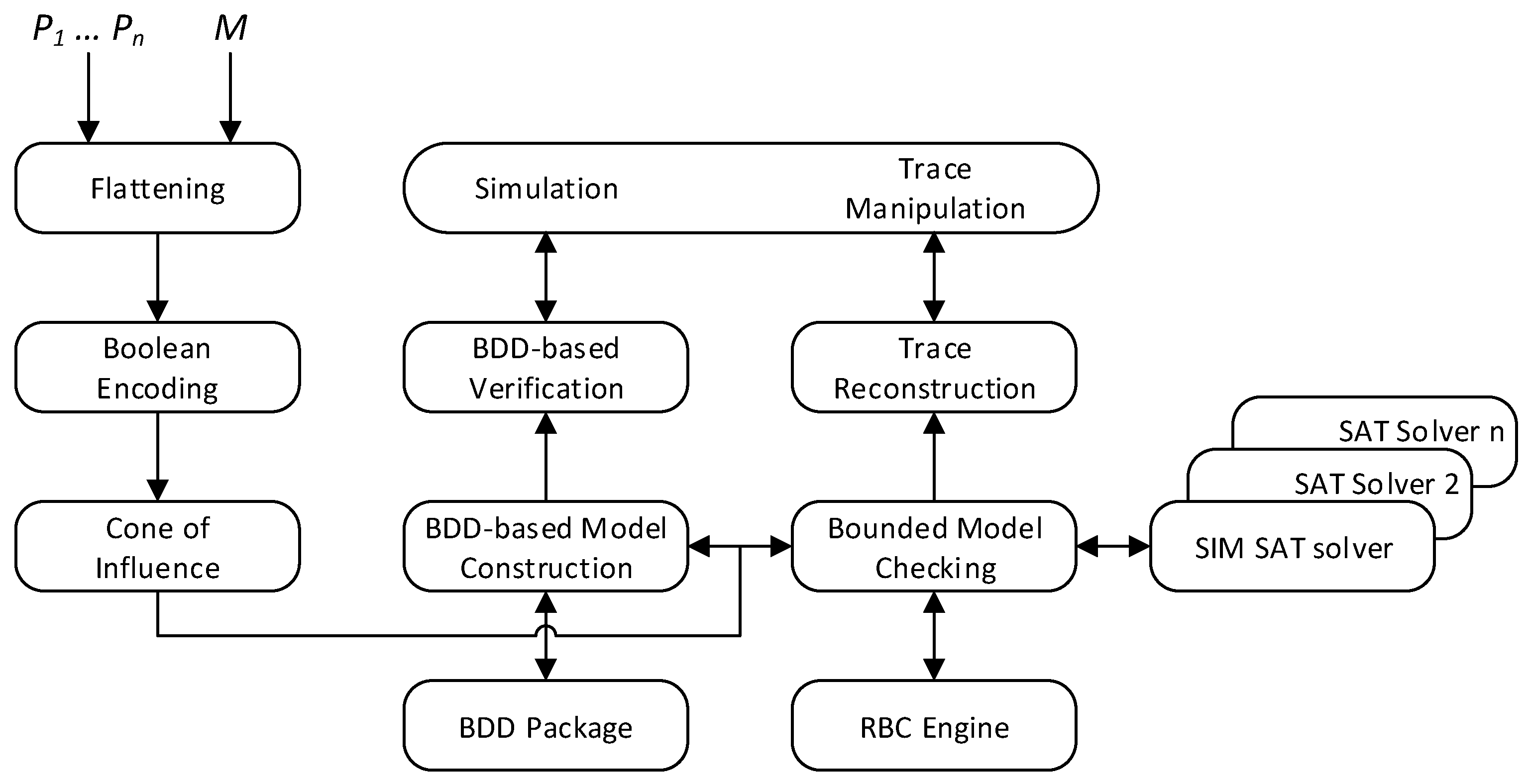
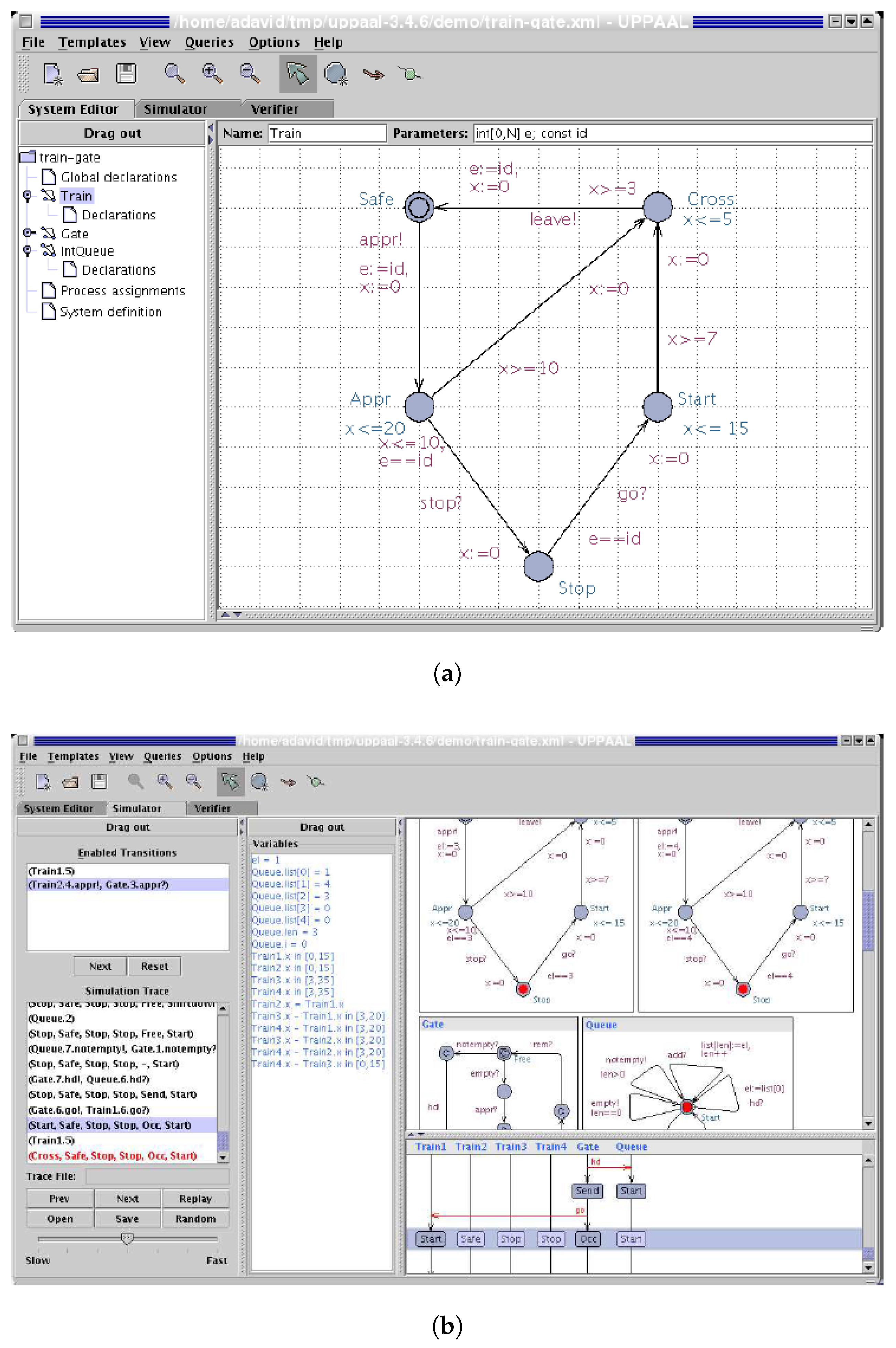
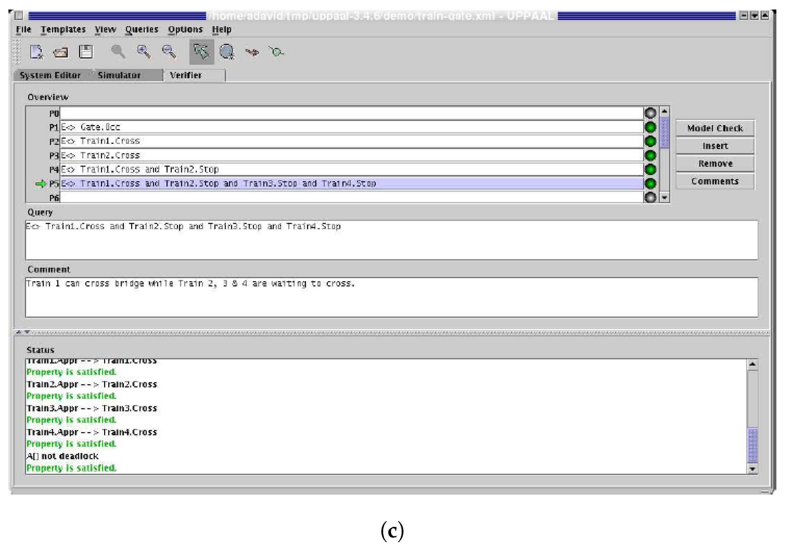
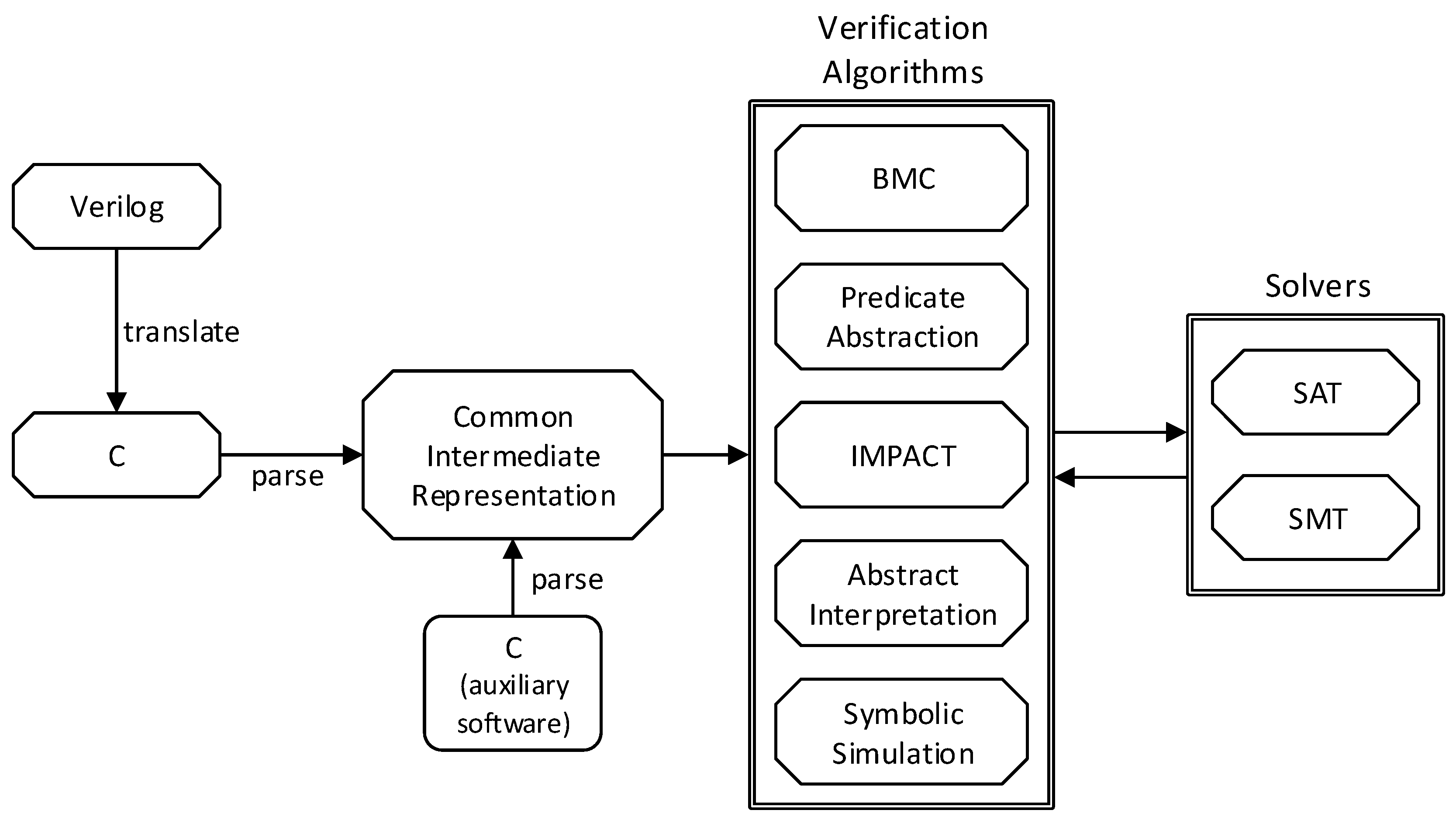
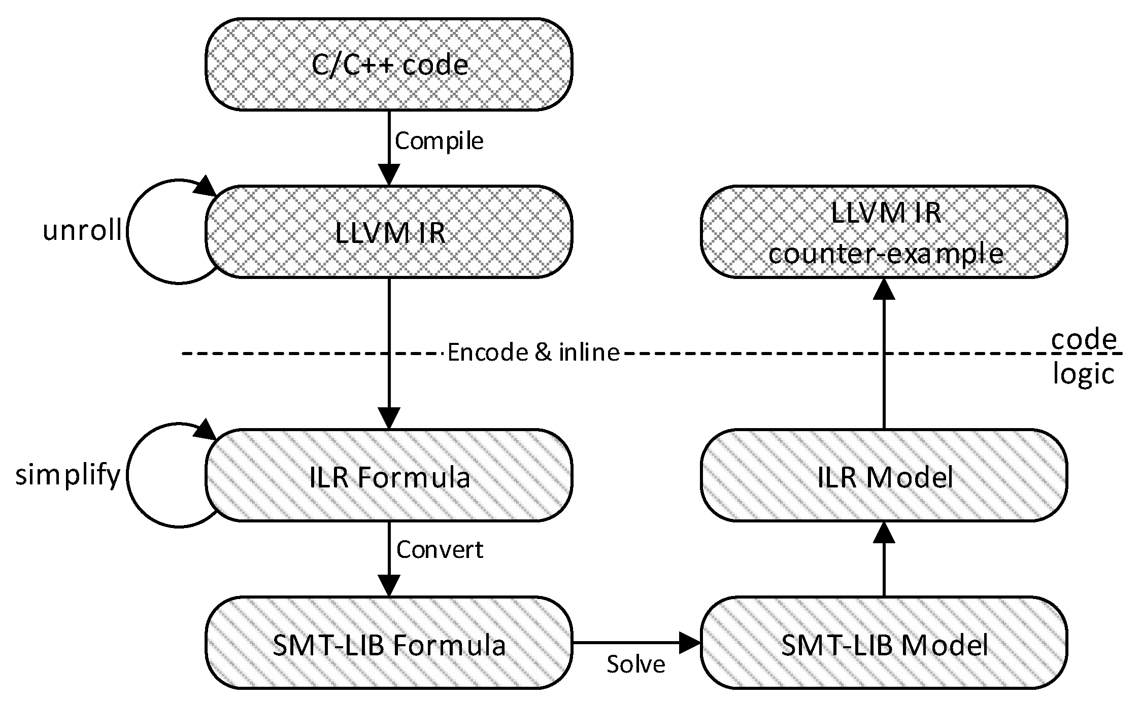
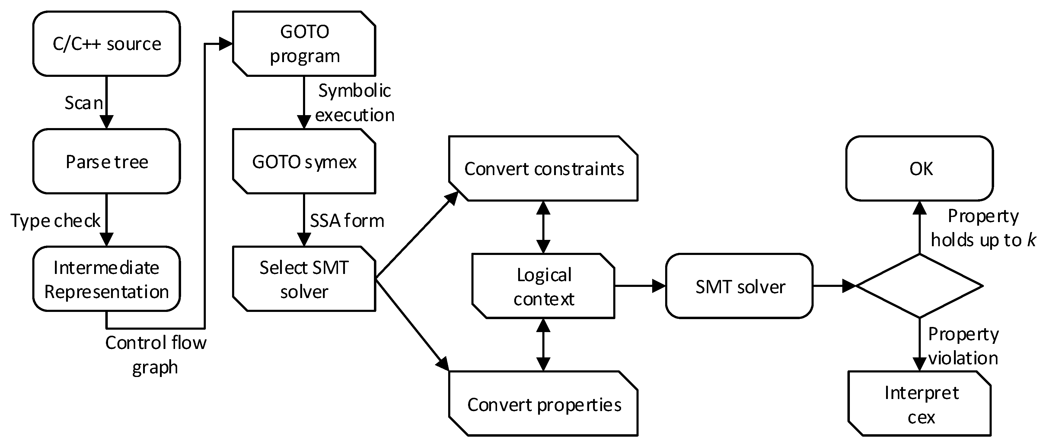
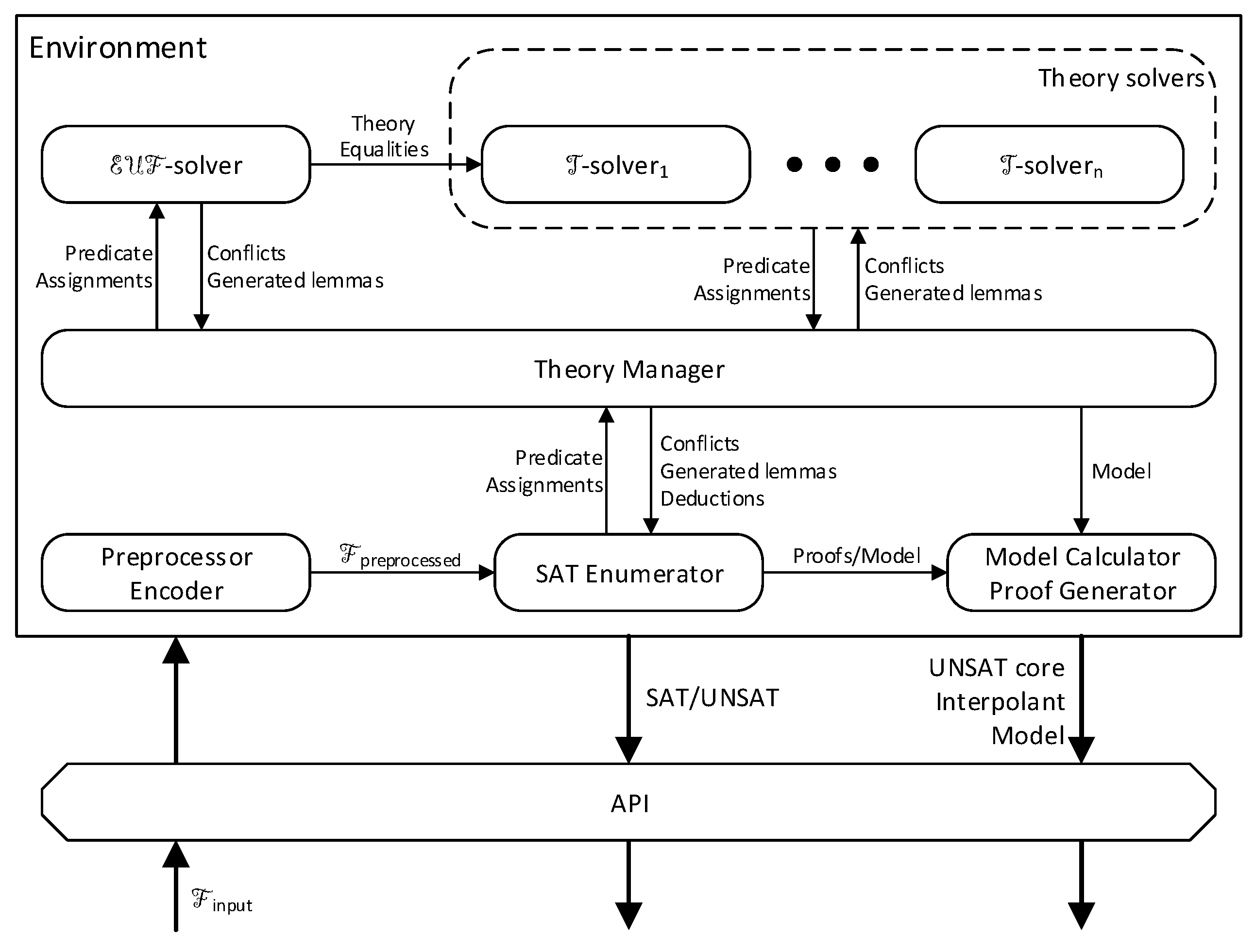
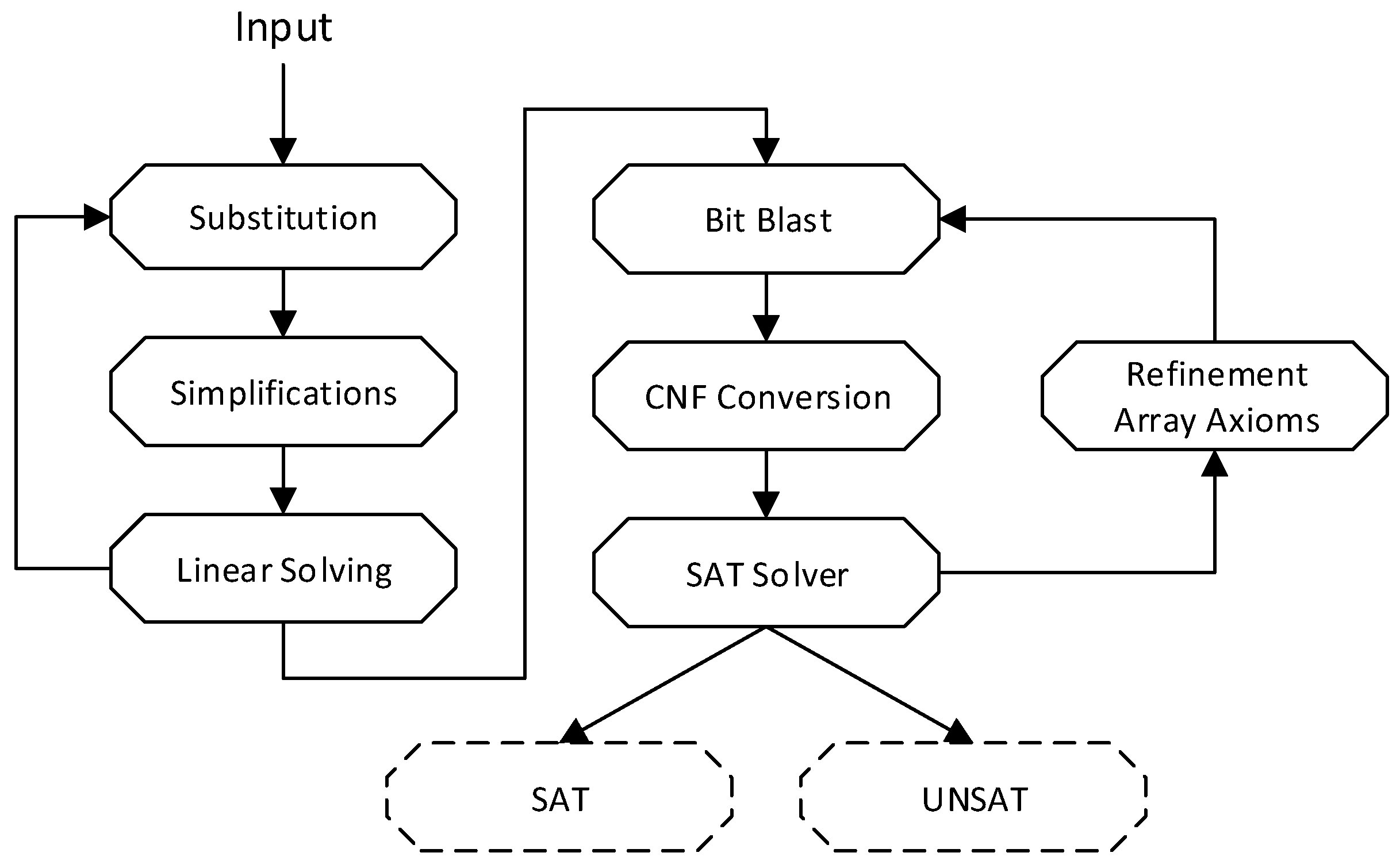
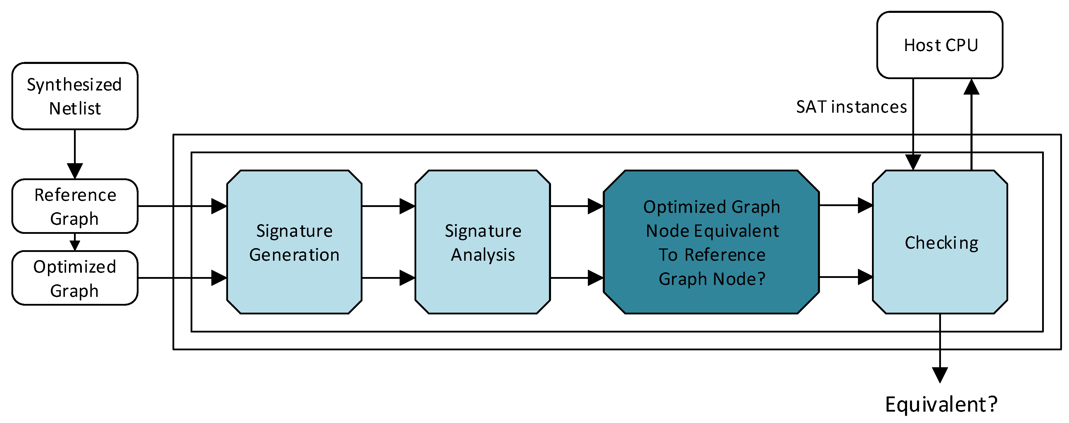
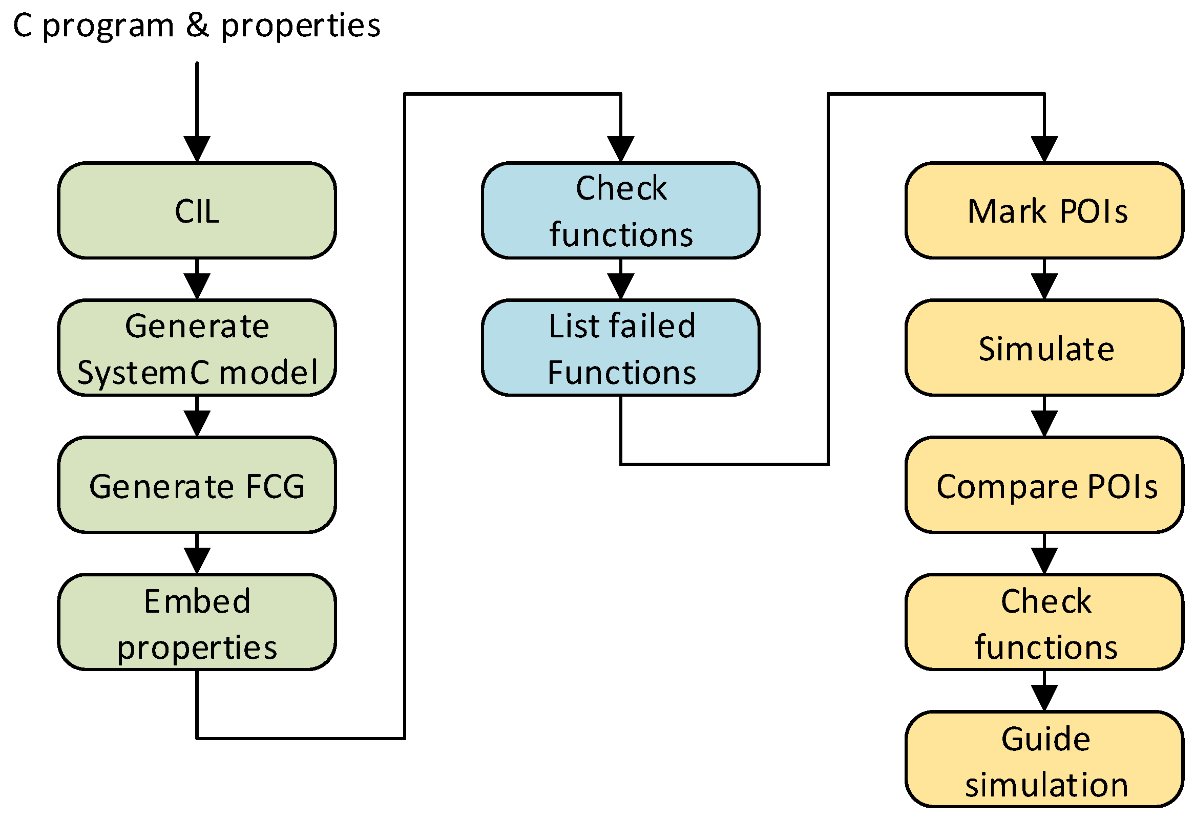
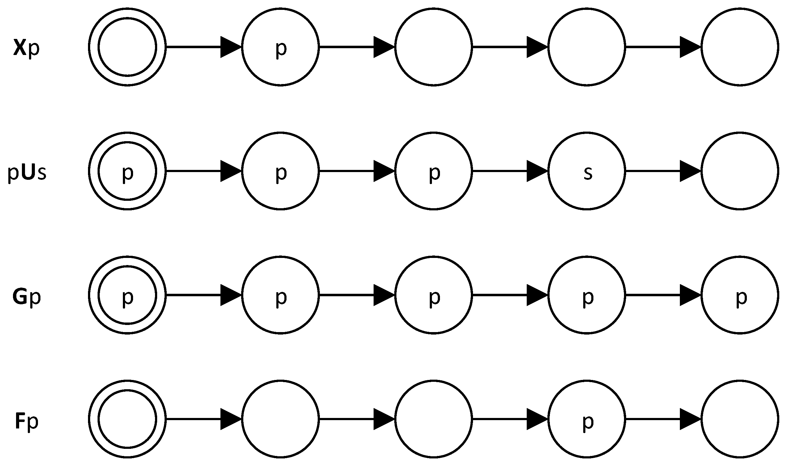
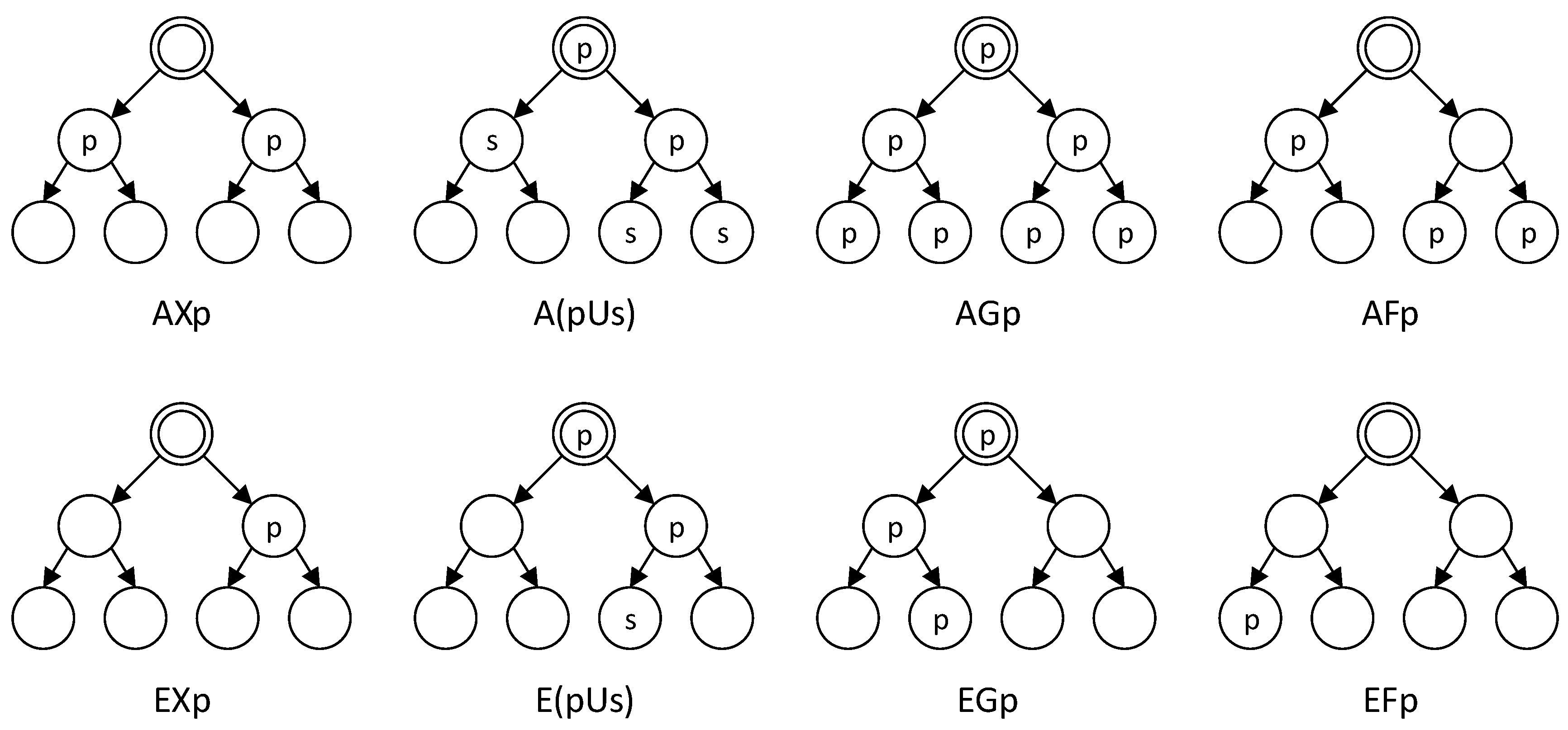
Table 1.
Characteristics from different formalisms for Automated Theorem Proving.
| Formalism | Automation degree | Expressiveness | Validity |
|---|---|---|---|
| Propositional logic | High | Low | Decidable |
| Temporal logic | High | Low | Decidable |
| First-order logic | Partial | Medium | Semidecidable |
| Higher-order logic | Low | High | Not even semidecidable |
Table 2.
Comparison of all techniques for different aspects of the development flow.
| Techniques | Applicability | Target | Coverage | Exhaustive | Testbench |
|---|---|---|---|---|---|
| Automated Theorem Proving | Early | Sub-block | High | Yes | No |
| Symbolic Model Checking | Early | IP | High | Yes | No |
| Bounded Model Checking | Early | IP | High (bounded) | Shallow | No |
| SMT Model Checking | Early | IP | High | Shallow | No |
| Equivalence Checking | Late | System | —1 | No | No |
| Static Analysis | Early | IP/System | —1 | —1 | No |
| Semiformal Verification | Late | System | Partial | No | Yes |
1 Not Applicable
© 2018 by the authors. Licensee MDPI, Basel, Switzerland. This article is an open access article distributed under the terms and conditions of the Creative Commons Attribution (CC BY) license (http://creativecommons.org/licenses/by/4.0/).
Share and Cite
MDPI and ACS Style
Grimm, T.; Lettnin, D.; Hübner, M. A Survey on Formal Verification Techniques for Safety-Critical Systems-on-Chip. Electronics 2018, 7, 81. https://doi.org/10.3390/electronics7060081
AMA Style
Grimm T, Lettnin D, Hübner M. A Survey on Formal Verification Techniques for Safety-Critical Systems-on-Chip. Electronics. 2018; 7(6):81. https://doi.org/10.3390/electronics7060081
Chicago/Turabian StyleGrimm, Tomás, Djones Lettnin, and Michael Hübner. 2018. "A Survey on Formal Verification Techniques for Safety-Critical Systems-on-Chip" Electronics 7, no. 6: 81. https://doi.org/10.3390/electronics7060081
Note that from the first issue of 2016, this journal uses article numbers instead of page numbers. See further details here.