Method of Estimating Human Orientation Using Array Antenna
by
Nobuyuki Shiraki
1,*,†, 
Zhixiong Chen
1,†,
Dai Sasakawa
1,†,
Naoki Honma
1,†,
Takeshi Nakayama
2,† and
Shoichi Iizuka
2,† 1
Graduate School of Arts and Science, Iwate University, Morioka 020-8551, Japan
2
Panasonic Corporation, Kadoma 571-8501, Japan
*
Author to whom correspondence should be addressed.
†
These authors contributed equally to this work.
Electronics 2018, 7(6), 92; https://doi.org/10.3390/electronics7060092
Submission received: 24 April 2018
/
Revised: 21 May 2018
/
Accepted: 4 June 2018
/
Published: 7 June 2018
(This article belongs to the Special Issue Data Processing and Wearable Systems for Effective Human Monitoring)
Abstract
:This paper presents a method that uses microwaves to estimate human body orientation. The antennas are arranged to surround the human and observe vital signs such as respiration and heart beat from the microwaves reflected from the human. Since the signal reflected from the front of the human will fluctuate the most, mainly due to respiration, human body orientation is estimated by finding the antenna that captures the largest rhythmic fluctuation. In experiments with three subjects, the median value of angular error of human orientation was 9.01∼23.35°.
1. Introduction
Recently, demand for effective and efficient monitoring systems has been rising due to the increased number of elderly people. As for the monitoring of such people, detecting their orientations is an important issue because this information is convenient in estimating the status of the observee. Though monitoring them by camera [1] is the easiest way to know the orientation information of the observee, this may violate privacy. Infrared-based systems [2] will not violate the privacy, but they are weak against sunlight and changes in air temperature.
To avoid these problems, the use of microwave sensors is being studied [3,4,5]. Since this technology uses radio waves, there is little invasion of privacy. It is also more robust to sunlight and temperature. WiTrack technology is a conventional method that uses microwaves [6]. In this technique, the distance range between the human and the antenna is estimated from the time of flight, the time taken for the signal to be reflected from the living body and captured by the receiver; human position is estimated using the time of flight from the multiple antennas. However, there is a disadvantage that a broadband width more than 1.5 GHz is necessary to obtain sufficient distance resolution.
Multiple-Input Multiple-Output (MIMO) radar offers high localization accuracy even if the bandwidth is limited [7,8,9,10]. Many studies use MIMO radar for estimating body position. MIMO radar, which uses the direction of arrival/departure (DOA/DOD) of the vital sign signal, estimates the position of the living body from the positional relation of the transceiver. Even though position can be detected accurately, this technique cannot estimate body orientation.
This paper presents a method of estimating body orientation by using the temporal responses captured by multiple antennas. The multiple antennas are arranged around the human body so as to observe the directional characteristics of the signals reflected from the human body. It is expected that the amplitude of the signal observed by the antenna in the front of the human is largest as respiration movement is most significant at the front of the body. The technique proposed in this paper can estimate the orientation of the subject by observing the subject from various directions, but this is not suitable for the target positioning. In contrast, the array configuration for positioning cannot estimate the subject’s orientation because it must have the antenna element spacing around a half wavelength for estimating DOD/DOA and this means the all antenna elements are in similar direction from the subject. To detect the orientation of the subject by using the new antenna arrangement, we propose a new algorithm, which is explained more detailly in the following part of the paper. This is major difference from our previous works [8,9,10].
2. Method of Estimating Body Orientation Using Array Antenna
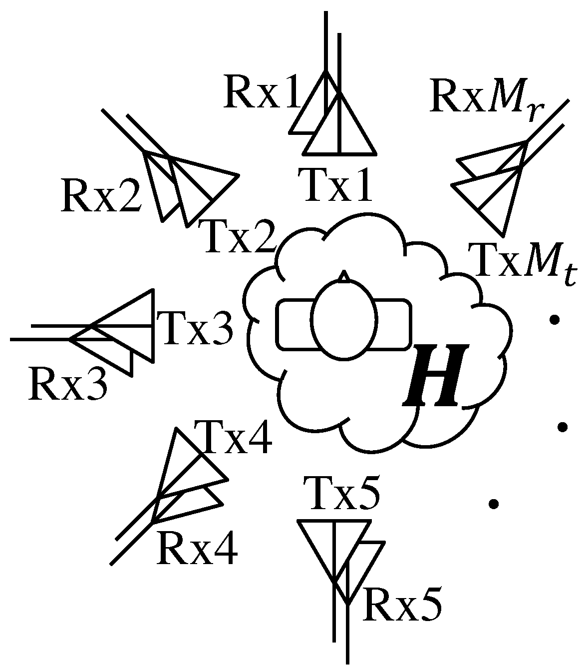
Figure 1 shows a conceptual diagram of the proposed method. Antennas are placed so as to surround the human and capture their respective time-variant channel. Using a transmitter and receiver with and element antennas, respectively, creates MIMO time-variant channels, defined as
represents the channel from the jth transmitter element to the ith receiver element. The absolute channel value, , is used for identifying body orientation in the following procedure.
Figure 2 shows the method of extracting the change of intensity, termed ‘prominence’ [11]. Prominence of a peak means stand out compared to around other peaks. This method consists of three steps.
- Step 1:
- When absolute value the channel has N peaks, the time of the Lth peak is . We draw a line horizontally from until it hits a higher peak to the left and right; let and be the times at which the line intersects the left and right peaks, respectively. When there is no higher peak, , are taken to be the ends of the signal.
- Step 2:
- When the minimum values between and and between and are and ,
- Step 3:
- If is the larger of and , the prominence at is expressed asis called prominence. The total value of the prominence of the channel from transmitting antenna j to receiving antenna i is expressed asThe sum of the prominences of all receiving antennas generated by transmitting antenna j is expressed as
This calculation is performed for all transmitting antennas. As expected, the signal from the transmitter facing the front of the subject tends to be more strongly influenced by respiration than those of the other transmitters. Therefore, the sum of the prominences of the transmitter facing the front of the body is the largest, and has the largest variation. The values of the transmitters on either side of the transmitter facing the front of the body exhibit the next largest variation. The orientation of the body is estimated by subjecting the top three transmitters (ranked in decreasing order of total prominence) to Lagrangian interpolation to find the peak orientation. However, when the transmitter with the second largest total prominence is not next to the transmitter with the largest prominence, it is assumed that it cannot be estimated and this data is not used.
3. Experiment
3.1. Calibration
Before carrying out the experiment, we performed calibration of the system, where the sensitivity and transmission power (amplitude) are conditioned. To do this, we connected the transmitter and receiver directly using cables.
3.2. Measurement Conditions
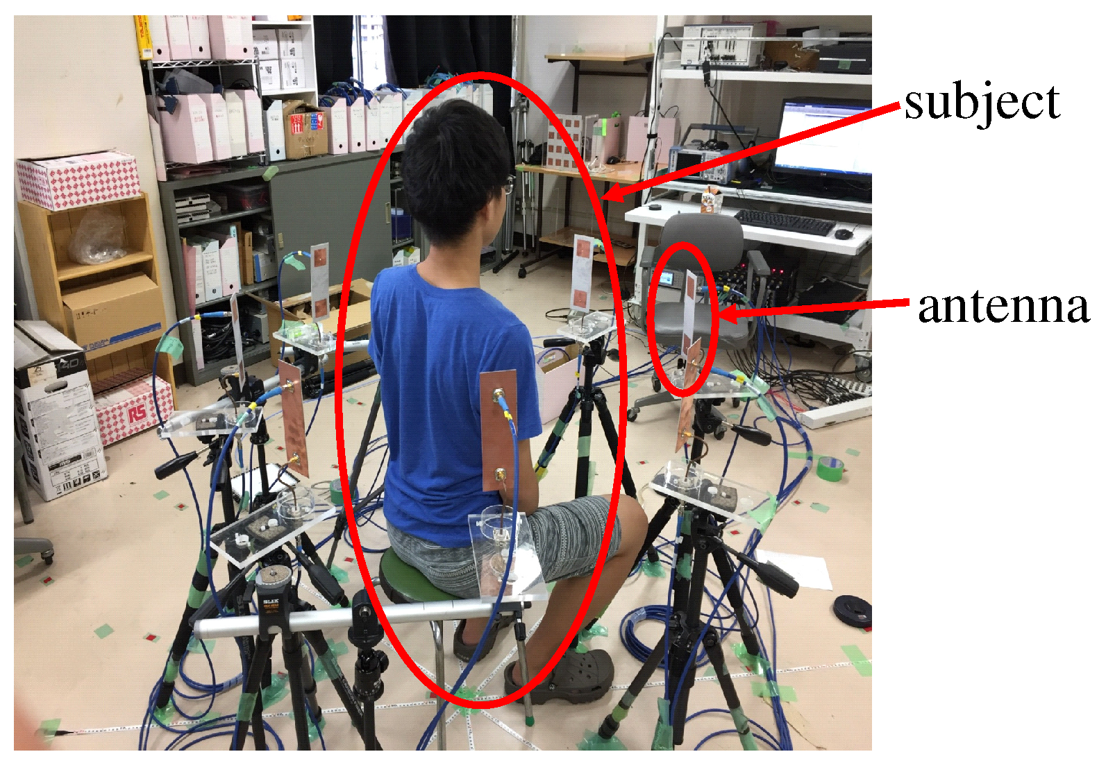
Figure 3 shows the antenna arrangement used in this experiment and the antenna elements. Figure 4 shows a photo of a typical measurement run and Table 1 shows the experimental conditions. Eight transmitter and eight receivers were used, both in a circular array. The frequency is 2.47 GHz, and the antenna height is 80 cm from the floor, the observation time is set to 25 seconds. The sampling frequency of MIMO channel is set to 100 Hz, which is much higher than the maximum frequency of the vital-sign, i.e., 3.3 Hz. The antennas were arranged at 45° intervals around the subject. In order to measure vertical reflection wave, the distance between transmitter and receiver is 1 . Three subjects sat on a chair centered on the array facing 16 directions at 22.5° intervals. In addition, the instant prominence values, , less than 0.1 were neglected to alleviate the noise effect. The power transmitted by the antenna is 10 dBm.
Our experiment was conducted considering the influence on the living body. The Ministry of Internal Affairs and Communications of Japan mandates radio radiation protection guidelines for human exposure to electromagnetic fields. From the guideline, it is supposed that there is no problem when the distance between antenna and living body is more than 20 cm and the power is less than 20 dBm. Since the power used in our experiment was 10 dBm, our experiment complied with the guidelines. Also, from expression of attenuation constant of lossy dielectrics, penetration depth of skin and muscle are less than 2 cm. Since the penetration depth is short, the microwave does not pass through the human body. Furthermore, 51.71% of transmit power are reflected by skin from the calculation result of Fresnel’s reflection coefficient, and very limited amount of the power propagates into the body.
Figure 5 shows the S-parameter of the antenna using in this experiment. | and mean reflection of transmitter and receiver, respectively. and mean mutual coupling of transmitter and receiver antennas. From this figure, mutual coupling and reflection of the used antenna at the operating frequency are about −22 dB and −14 dB, respectively. Normally, the antenna spacing larger than a wavelength is sufficient for obtaining the mutual coupling lower than −15 dB. In fact, the mutual coupling in our antenna was dB, which is sufficient for observing the reflected signal for our testbed. Also, Fraunhofer distance is calculated by = 0.25 m (D is the antenna aperture, which is 0.125 m), which is the boundary of near and far fields. Therefore, it can be understood that this measurement is performed at the far field range because the distance between the antenna and the subject was set to 0.5 m.
Figure 6 and Figure 7 show vertical- and horizontal-polarization radiation pattern, respectively. From Figure 6, the main lobes of both antennas direct forward (0 degree), whereas their back lobe at 180 degree has low gain. In contrast, Figure 7 shows the gain of both antennas is quite low because this is a cross-polarization components.
3.3. Measured Results
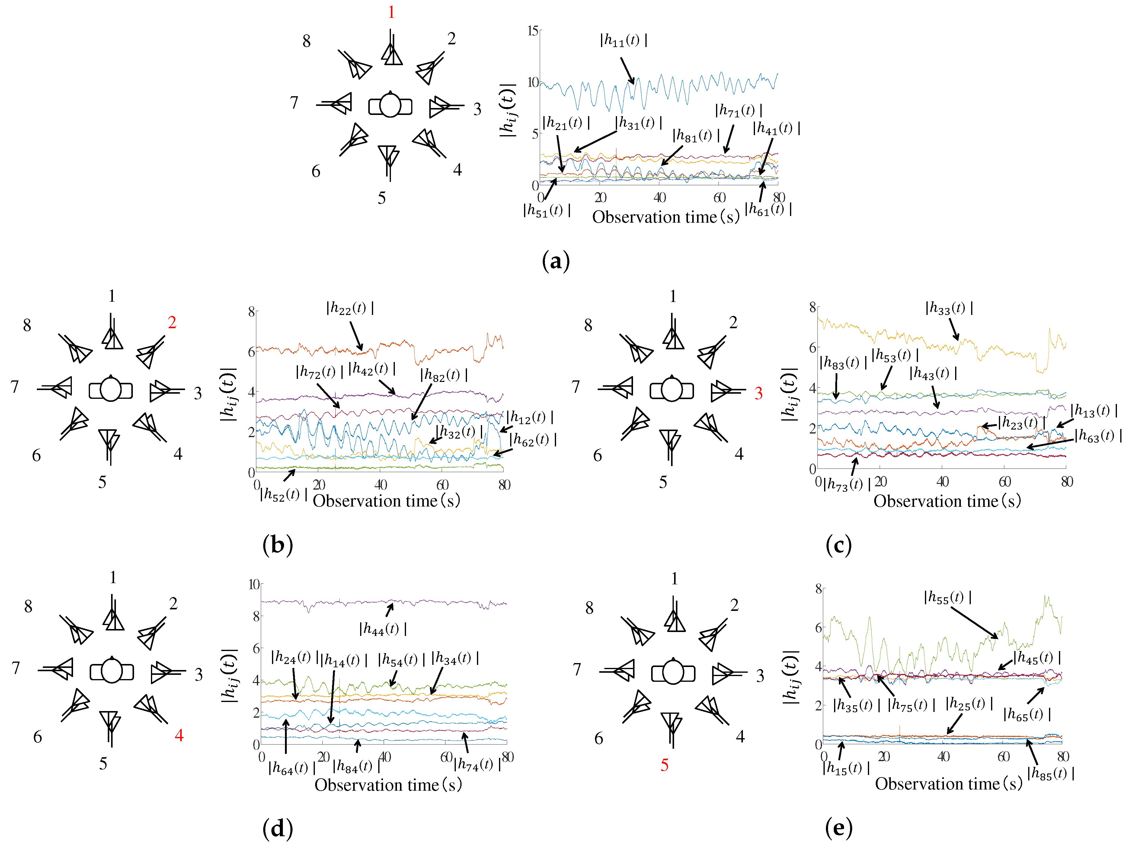
Figure 8 shows the absolute value transmitted from each transmitter and received all receiver. In these figures, the target is directed to TRx1. In terms of the diagonal components of the channel matrix, it can be seen that the largest channel fluctuation is observed by TRx1, i.e., both of the transmitter and receiver antennas are at the front side of the living body, whereas only the small fluctuations are observed by other antennas. This behavior is due to a respiratory movement. Furthermore, the non-diagonal components of the channel matrix have weak intensity, but still seem to contain the vibration due to the respiration.
Figure 9 show the amplitude transmitted from each transmitter and received all receiver. In these figures, the target faces the direction to TRx1. From these figures, it can be seen that the combination of the antennas transmitted and received from the front of the living body has the largest amplitude and regular cycle. The largest amplitude and regular cycle are assumed to be affected by breathing fluctuation.
Figure 9 shows an example of the absolute value of a channel when the subject faced the Tx1 and Rx1 direction. From the figure, we can see that channel yielded by the antenna directly facing the subject was greatly altered by the biological activity.
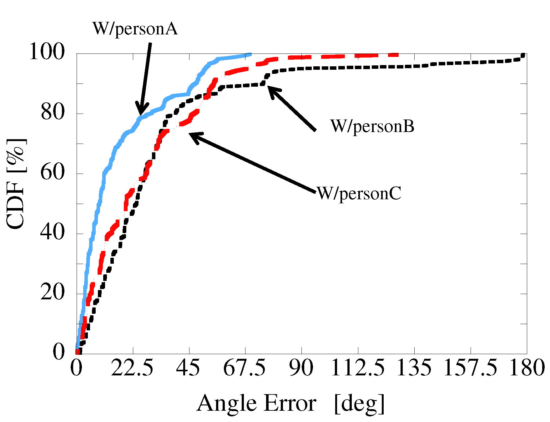
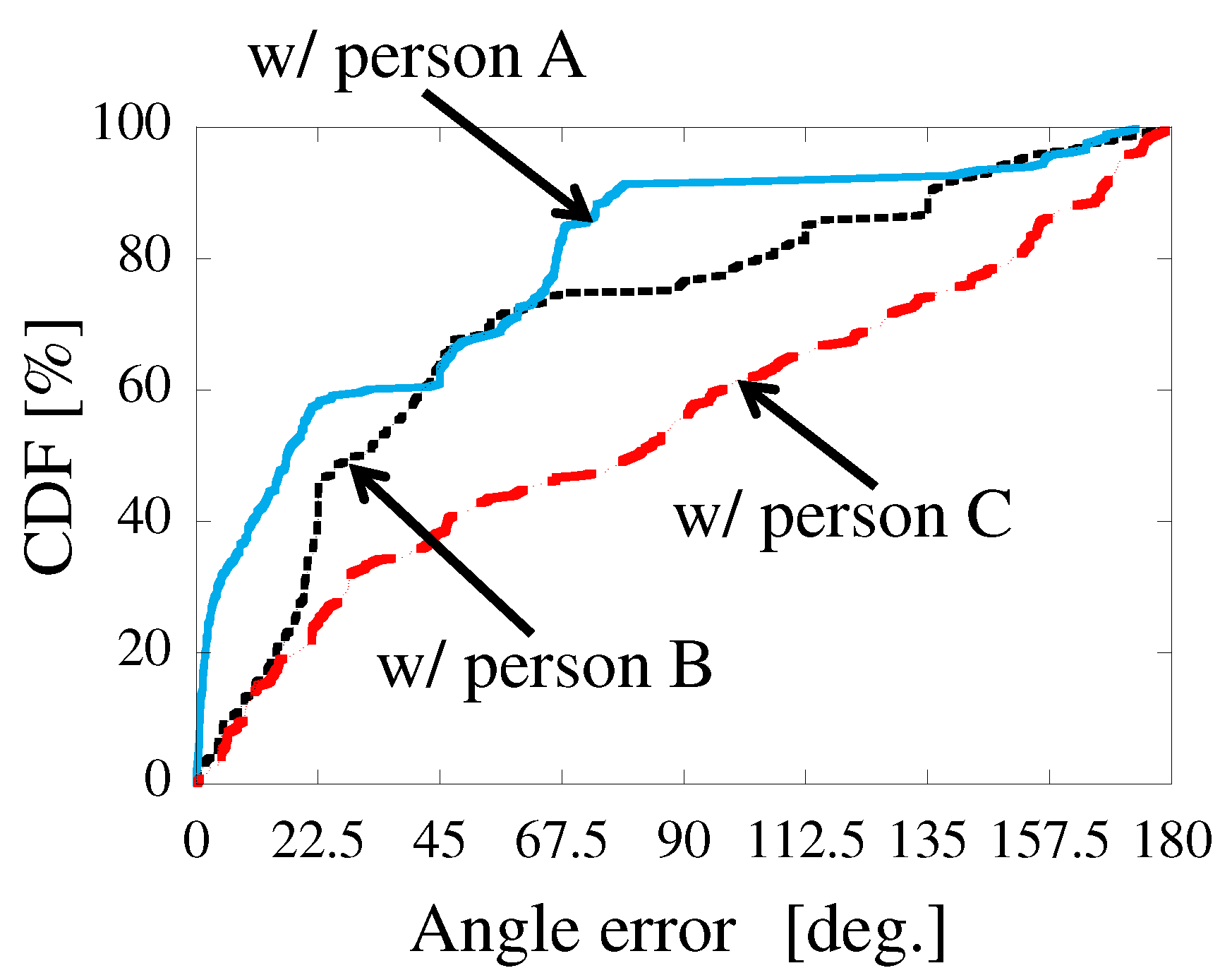
Figure 10 shows the Cumulative Distribution Function (CDF) of the orientation estimation error for each subject. From the figure, median values of estimation error of subjects A, B, C were 9.01°, 22.35°, and 20.33°, respectively.
Figure 11 shows the CDF of the angular estimation error of three subjects when the only diagonal components of MIMO channel are used for detecting the subjects’ orientation. It is found that the estimation accuracies at 50% value degraded by 5.86∼53.74° compared to the results shown in Figure 10. This means the MIMO scheme, i.e., use of the non-diagonal components can enhance the accuracy of the orientation detection.
4. Conclusions
In this paper, we proposed a method of estimating human body orientation from changes in the intensity of microwave signals. Experiments confirmed that the antenna directly front of the subject experienced the largest channel fluctuation. The median values of the angular estimation error with three subjects ranged from 9.01° to 23.35°, and this means the proposed method can well estimate the orientation of the human body without any prior knowledge.
Also, the wavelength in this frequency is about 12 cm, and the movement of the subject’s body is smaller than this value since the subject is seated. Nevertheless, the positional error is quite important issue for this system, and this will be investigated in our future study.
Author Contributions
N.S., Z.C., D.S. and N.H. designed the study; N.S., Z.C., T.N. and S.I. performed the experiments; N.S. and Z.C analyzed the data; N.S. wrote the paper; D.S. and N.H. supervised the manuscript.
Conflicts of Interest
The authors declare no conflict of interest.
Abbreviations
The following abbreviations are used in this manuscript:
| MIMO | Multiple-Input Multiple-Output |
| CDF | Cumulative Distribution Function |
| DOA | Direction Of Arrival |
| DOD | Direction Of Departure |
References
- Fiore, L.; Fehr, D.; Bodor, R.; Drenner, A.; Somasundaram, G.; Papanikolopoulos, N. Multi-camera human 240 activity monitoring. Intell. Robot. Sys. 2008, 52, 5–43. [Google Scholar] [CrossRef]
- Norbert, N.; Thierry, H.; Vincent, R.; Gilles Eric, M.; Gilles, M.; Aldo, M.; Thieny, P.; Porcheron, T. Monitoring behavior in home using a smart fall sensor and position sensors. In Proceedings of the 1st Annual International, Conference, Microtechnologies in Medicine and Biology, Lyon, France, 12–14 October 2000; pp. 607–610. [Google Scholar] [CrossRef]
- Lin, J.C. Noninvasive microwave measurement of respiration. Proc. IEEE 1975, 63, 1530. [Google Scholar] [CrossRef]
- Droitcour, A.; Lubecke, V.; Lin, J.; Boric-Lubecke, O. A microwave radio for Doppler radar sensing of vital signs. In Proceedings of the 2001 IEEE MTT-S International, Microwave Symposium Digest, Phoenix, AZ, USA, 20–24 May 2001; pp. 175–178. [Google Scholar] [CrossRef]
- Avagyan, H.; Hakhoumian, A.; Hayrapetyan, H.; Pogosyan, N.; Zakaryan, T. Portable non-contact microwave Doppler radar for respiration and heartbeat sensing. Am. J. Phys. 2012, 5, 8–14. [Google Scholar]
- Adib, F.; Kabelac, Z.; Katabi, D.; Miller, R.C. 3D Tracking via Body Radio Reflections. In Proceedings of the 11th USENIX Conference on Networked Systems Design and Implementation (NSDI’14), Seattle, WA, USA, 2–4 April 2014; pp. 317–329. [Google Scholar]
- Li, J.; Stoica, P. MIMO Radar Signal Processing; John Wiley & Sons, Inc.: Hoboken, NJ, USA, 2009; ISBN 978-0470178980. [Google Scholar]
- Konno, K.; Honma, N.; Sasakawa, D.; Tsunekawa, Y.; Nishimori, K.; Takemura, N.; Mitsui, T. Localizing multiple target using bistatic MIMO radar in multi-path environment. In Proceedings of the 2014 IEEE International Workshop on Electromagnetics (iWEM), Sapporo, Japan, 4–6 August 2014; pp. 90–91. [Google Scholar] [CrossRef]
- Konno, K.; Honma, N.; Sasakawa, D.; Nishimori, K.; Takemura, N.; Mitsui, T.; Tsunekawa, Y. Estimating living-body location using bistatic MIMO radar in multi-path environment. IEICE Trans. Commun. 2015, 98, 2314–2321. [Google Scholar] [CrossRef]
- Konno, K.; Nango, M.; Honma, N.; Nishimori, K.; Takemura, N.; Mitsui, T. Experimental evaluation of estimating living-body direction using array antenna for multipath environment. IEEE Antennas Wirel. Propag. Lett. 2014, 13, 718–721. [Google Scholar] [CrossRef]
- Marcos, L. Building past landscape perception with GIS: Understanding topographic prominence. Archaeol. Sci. 2001, 28, 1005–1014. [Google Scholar]
Figure 1.
Conceptual diagram.

Figure 2.
Calculation method using prominence in three steps: (a) Step 1; (b) Step 2; (c) Step 3.

Figure 3.
Used antennas and antenna arrangement. (a) Tx/Rx configuration; (b) The antennas used in the experiments.
Figure 3.
Used antennas and antenna arrangement. (a) Tx/Rx configuration; (b) The antennas used in the experiments.
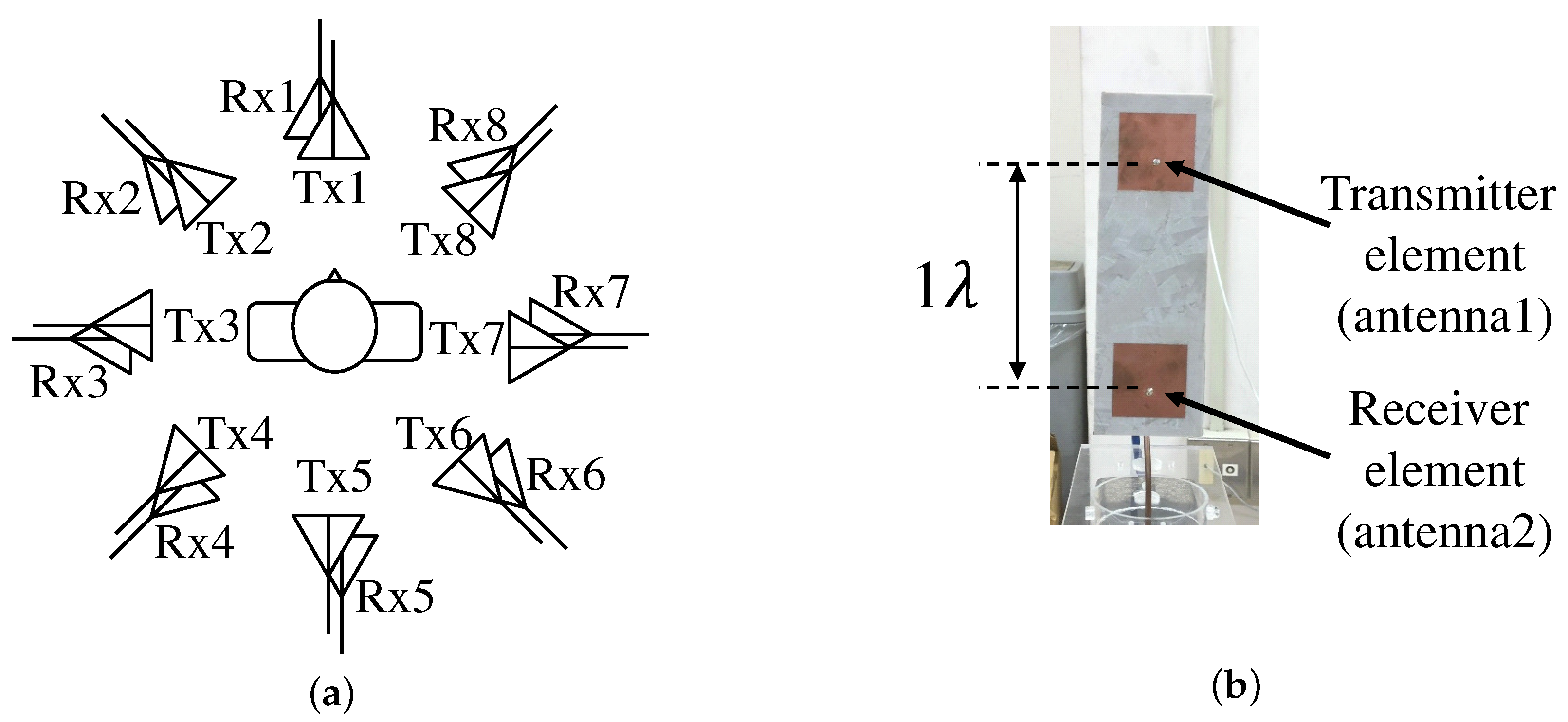
Figure 4.
Photo of a measurement run.

Figure 5.
S-parameter.

Figure 6.
vertical-polarization radiation pattern; (a) antenna 1; (b) antenna 2.
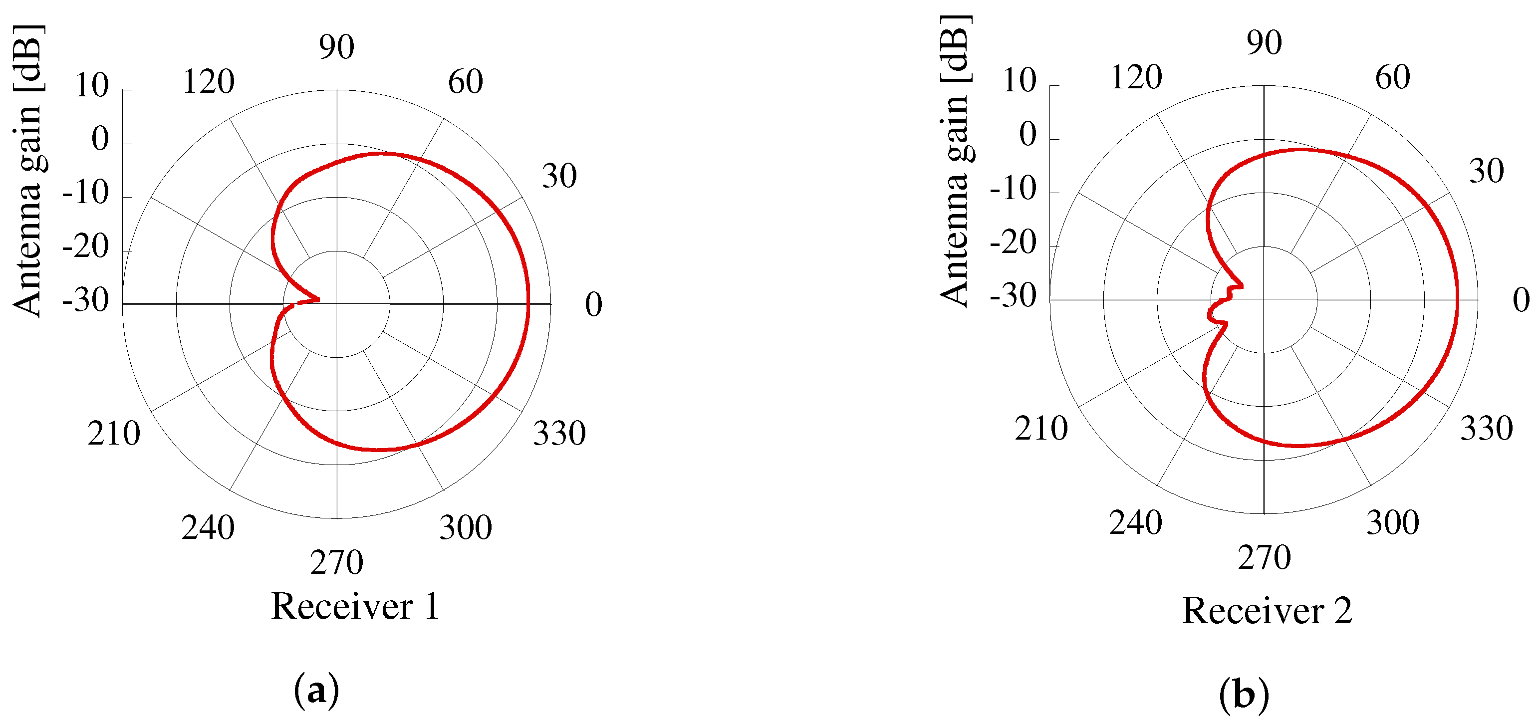
Figure 7.
horizontal-polarization radiation pattern; (a) antenna 1; (b) antenna 2.
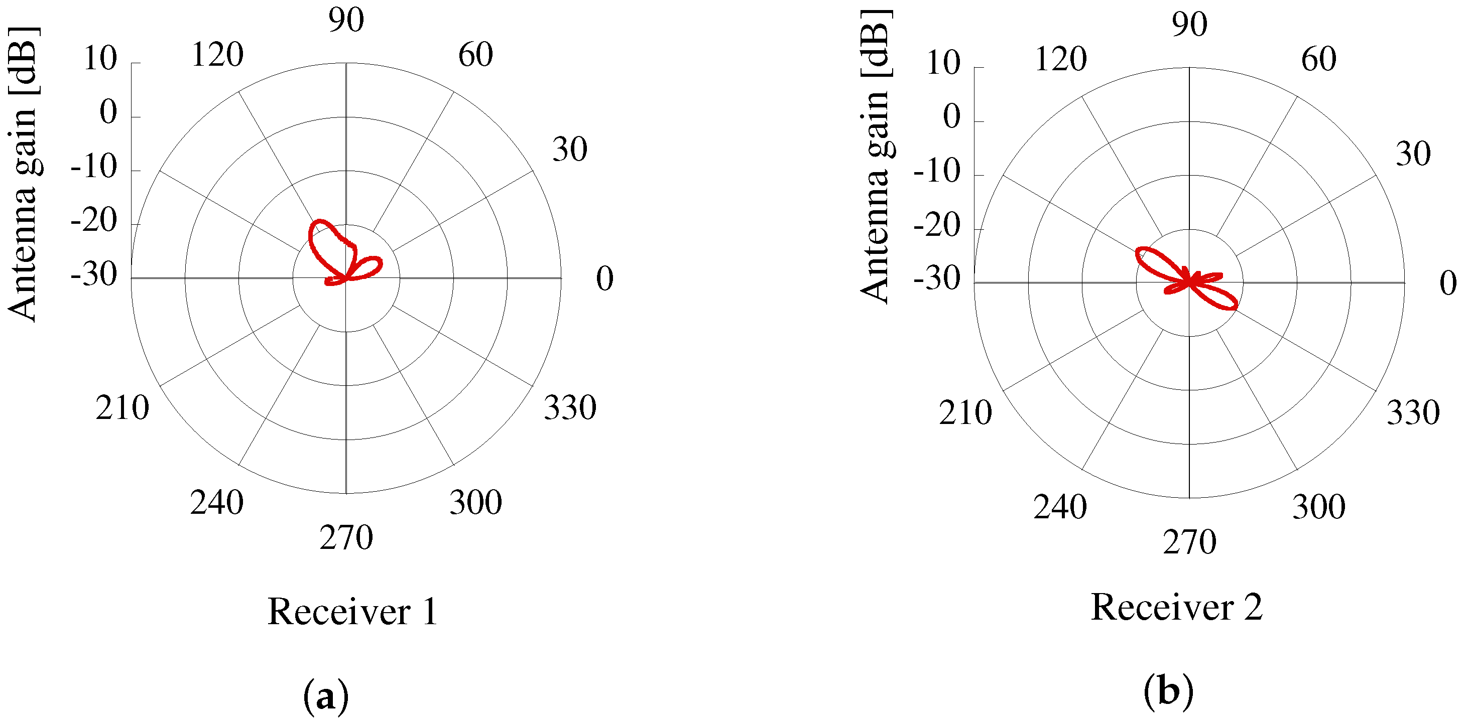
Figure 8.
The absolute value transmitted from each transmitter and received all receiver. (a) transmitted from Tx1; (b) transmitted from Tx2; (c) transmitted from Tx3; (d) transmitted from Tx4; (e) transmitted from Tx5.
Figure 8.
The absolute value transmitted from each transmitter and received all receiver. (a) transmitted from Tx1; (b) transmitted from Tx2; (c) transmitted from Tx3; (d) transmitted from Tx4; (e) transmitted from Tx5.

Figure 9.
Absolute value of a channel.
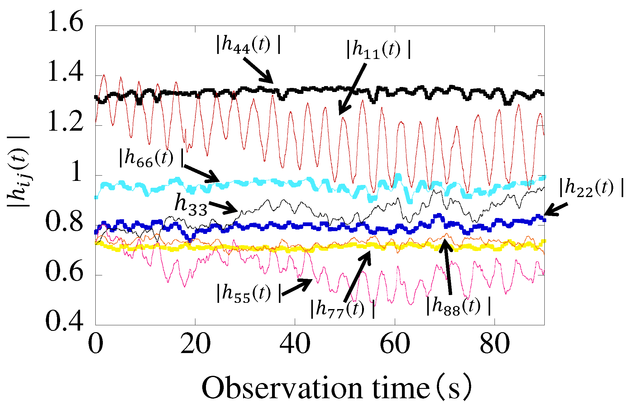
Figure 10.
CDF of the orientation estimation error.

Figure 11.
CDF of the orientation estimation error(only diagonal components).


Table 1.
Measurement conditions.
| Antenna Element | 8-Element Circular Array Antenna |
|---|---|
| Distance between Tx and Rx | 1 |
| Height of the Rx | 80 cm |
| Distance between the antenna and the subject | 50 cm |
| Frequency | 2.47125 GHz |
| Sampling frequency | 100 Hz |
| Channel measurement time | 25 s |
| Human orientation | 16 directions (22.5° intervals) |
| Transmission power | 10 dBm |
© 2018 by the authors. Licensee MDPI, Basel, Switzerland. This article is an open access article distributed under the terms and conditions of the Creative Commons Attribution (CC BY) license (http://creativecommons.org/licenses/by/4.0/).
Share and Cite
MDPI and ACS Style
Shiraki, N.; Chen, Z.; Sasakawa, D.; Honma, N.; Nakayama, T.; Iizuka, S. Method of Estimating Human Orientation Using Array Antenna. Electronics 2018, 7, 92. https://doi.org/10.3390/electronics7060092
AMA Style
Shiraki N, Chen Z, Sasakawa D, Honma N, Nakayama T, Iizuka S. Method of Estimating Human Orientation Using Array Antenna. Electronics. 2018; 7(6):92. https://doi.org/10.3390/electronics7060092
Chicago/Turabian StyleShiraki, Nobuyuki, Zhixiong Chen, Dai Sasakawa, Naoki Honma, Takeshi Nakayama, and Shoichi Iizuka. 2018. "Method of Estimating Human Orientation Using Array Antenna" Electronics 7, no. 6: 92. https://doi.org/10.3390/electronics7060092
Note that from the first issue of 2016, this journal uses article numbers instead of page numbers. See further details here.